

Page 1

Grason-Stadler
®
GSI TympStar Versions 1 and 2
Middle-Ear Analyzer
Reference Instruction Manual 2000-0110, Rev3.0
Printed October, 2002
Grason-Stadler - A Division of VIASYS Healthcare
5225 Verona Road, Building 2, Madison, WI 53711
TEL: 608-441-2323, 800-700-2282, FAX: 608-441-2234
Service Manual
GSI
Grason-Stadler
Page 2

Title: GSI TympStar Versions 1 and 2
Middle-Ear Analyzer
Service Manual
Date: October, 2002
Copyright © 2001 Grason-Stadler. All rights reserved. No part of this publication may be reproduced or
transmitted in any form or by any means without the prior written permission of Grason-Stadler. The information
in this publication is proprietary to Grason-Stadler.
Part number: 2000-0110
Printing history: November, 2001 First printing Rev 1.0
June, 2002 Second printing Rev 2.0
October, 2002 Third printing Rev 3.0
Page 3

Warranty for the GSI TympStar Versions 1 & 2
Grason-Stadler warrants the GSI TympStar Versions 1 and 2 to be free of original defects in material and
workmanship and to perform in accordance with manufacturers specifications for a period of one year
from the date of purchase. If this instrument or any component thereof is found to be defective or at
variance from the manufacturers specifications during the warranty period, Grason-Stadler will repair,
replace, or recalibrate the instrument or component at no cost to the purchaser.
This warranty only applies to instruments purchased new from Grason-Stadler or its authorized distributors or representatives. The purchaser must return the instrument directly to Grason-Stadler or an authorized GSI TympStar distributor or representative and bear the costs of shipping.
This warranty does not cover breakage or failure due to tampering, misuse, neglect, accidents, modification, or shipping, and is void if the instrument is not used in accordance with manufacturers recommendations or if repaired or serviced by other than Grason-Stadler or a Grason-Stadler authorized representative.
WARNING
The GSI TympStar Versions 1 and 2 are designed to be used with a hospital grade outlets.
Injury to personnel or damage to equipment can result when a three-prong adapter is connected between the instrumentss power plug and an A/C outlet or extension cord.
Accessory Hazard Warning
This IEC 601-l/CSA C22.2 No. 601.1M90 listed medical instrument should be interconnected with accessories that have proper electrical compatibility and which are listed as
conforming to Part 1: General Requirements for Safety of the UL Medical Electrical Equipment Standard UL2601-1. Connection of accessories not meeting these requirements may
result in electrical leakage currents in excess of those allowed by the standard and present a
potential electrical shock hazard to the person being tested.
Page 4

User manuals
Installation, setup and operating information can be found in the Reference
Instruction Manuals:
TympStar Version 1: 2000-0100
TympStar Version 2: 2000-0120
Service personnel
Electrical safety
CMOS handling
Repair and/or bench testing of the GSI TympStar Version 1 and Version 2
instruments should be performed only by trained personnel. The following
instructions are provided primarily for use by persons who are skilled in the
repair of electronic equipment.
CAUTION
The GSI TympStar Version 1 and Version 2 instruments are
IEC 601-1/CSA approved; consequently if any parts are replaced during the repair of these units, only exact replacements should be made. Any alterations of the present electrical or mechanical construction or components will void
these safety approvals.
Many of the integrated circuits on the PC Boards are constructed of CMOS
and NMOS materials. Please observe the following precautions:
CAUTION
Failure to observe the following precautions whenever a circuit board or an integrated circuit package is handled can
result in damage to the GSI TympStar Version 1 or
Version 2 instrument. Please observe these precautions:
1) Place the instrument and parts on a grounded, conductive work
surface.
2) Ground yourself (with a strap having about 1 Meg-Ohm resistance)
to discharge or prevent static charges.
3) Ground the frame of any test instrument or soldering iron to be used.
4) If any circuit boards are to be stored or transported, enclose them in
conductive (antistatic) envelopes.
Page 5

Contents
Introduction ..................................1-1
General ..................................................................................................................... 1-1
Version 1 ................................................................................................................... 1-2
Version 1 equipment connections and options ..................................................... 1-2
Version 2 ................................................................................................................... 1-3
Version 2 equipment connections and options ..................................................... 1-3
The probe ................................................................................................................. 1-4
Instrument controls ................................................................................................. 1-5
Hardkeys and softkeys ......................................................................................... 1-5
Rotary pressure control ....................................................................................... 1-5
Test modes and menu navigation .......................................................................... 1-5
Changing parameter settings .................................................................................. 1-7
Menu diagrams ........................................................................................................ 1-7
GSI default parameter settings ............................................................................... 1-7
Specifications ...............................2-1
Introduction .............................................................................................................. 2-1
Standards ................................................................................................................. 2-1
Version 1 Specifications ................................................... 2-1
Sensitivity ranges .................................................................................................... 2-2
Probe signal .............................................................................................................2-2
Pneumatic System ................................................................................................... 2-3
Acoustic Reflex Activating (Stimulus) Signal......................................................... 2-3
Stimulus Presentation Control ................................................................................ 2-5
Temporal Specifications of Stimulus Presentation ............................................... 2-5
Environmental .......................................................................................................... 2-6
Warm-Up Time.......................................................................................................... 2-6
Calibration Stability.................................................................................................. 2-7
Connectors ............................................................................................................... 2-7
Electrical ................................................................................................................... 2-8
Supplied Accessories .............................................................................................. 2-9
Mechanical ............................................................................................................... 2-9
Materials of manufacture ........................................................................................ 2-9
Contents - 1GSI TympStar Version 1 and Version 2 Service Manual
Page 6

Table of Contents
Calibration requirements ......................................................................................... 2-9
Version 2 Specifications ................................................. 2-10
Standards ............................................................................................................... 2-10
Sensitivity ranges .................................................................................................. 2-11
Temporal Latency in ARLT Mode .......................................................................... 2-12
Multi Frequency ..................................................................................................... 2-12
Probe Signal (Sinusoidal) ...................................................................................... 2-12
Pneumatic System ................................................................................................. 2-13
Acoustic Reflex Activating (Stimulus) Signal....................................................... 2-13
Click Stimulus ........................................................................................................ 2-16
Stimulus .................................................................................................................. 2-16
Presentation Control.............................................................................................. 2-16
Temporal Specifications Of Stimulus Presentation ............................................ 2-17
Environmental ........................................................................................................ 2-17
Warm-Up Time........................................................................................................ 2-17
Calibration Stability................................................................................................ 2-18
Connectors ............................................................................................................. 2-18
Electrical ................................................................................................................. 2-19
Supplied Accessories ............................................................................................ 2-20
Mechanical ............................................................................................................. 2-20
Materials of manufacture ...................................................................................... 2-20
Calibration requirements ....................................................................................... 2-20
Operation summary......................3-1
Front panel controls ......................................................... 3-1
Hardkeys................................................................................................................... 3-2
Tymp ....................................................................................................................3-2
Reflex ................................................................................................................... 3-2
Etf ......................................................................................................................... 3-2
Special ................................................................................................................. 3-2
Page ..................................................................................................................... 3-2
Print ...................................................................................................................... 3-2
Remote ................................................................................................................. 3-2
Data Transfer ....................................................................................................... 3-2
Pressure control ................................................................................................... 3-2
Manual ................................................................................................................. 3-2
Hold ...................................................................................................................... 3-2
Stop ...................................................................................................................... 3-2
Start ...................................................................................................................... 3-3
Stimulus ............................................................................................................... 3-3
Intensity ................................................................................................................ 3-3
Contents - 2
Grason-Stadler
Page 7

Table of Contents
Present ................................................................................................................. 3-3
LCD hardkeys ........................................................................................................... 3-3
Clear .................................................................................................................... 3-3
Erase .................................................................................................................... 3-3
Return................................................................................................................... 3-3
Softkeys .................................................................................................................... 3-3
Menus and LCD screens ................................................. 3-4
Menus ....................................................................................................................... 3-4
Program modes ........................................................................................................ 3-5
Version 1 probe tone frequencies .......................................................................... 3-5
Version 2 probe tone frequencies .......................................................................... 3-5
Version 1 LCD graphic traces ................................................................................. 3-5
Version 2 LCD graphic traces ................................................................................. 3-5
Probe lights .............................................................................................................. 3-6
LCD screen............................................................................................................... 3-6
Erasing and clearing test data ................................................................................ 3-7
Version 2 External reflex test stimuli ..................................................................... 3-7
Paging test data ....................................................................................................... 3-7
Version 2 cursor....................................................................................................... 3-8
Printing tests ............................................................................................................ 3-8
Preparing an external printer .................................................................................. 3-8
Setting the printer parameters .............................................................................. 3-9
Left column printout data .................................................................................... 3-10
Color or black and white .................................................................................... 3-10
Changing Instrument Versions ....................................... 3-11
Changing from a Version 2 to a Version 1 ........................................................... 3-11
Switching to V1 temporarily ................................................................................ 3-12
Switching back to V2 .......................................................................................... 3-12
Switching to V1 permanently .............................................................................. 3-12
Changing from a Version 1 to a Version 2 ........................................................... 3-13
Obtaining a License Code .................................................................................. 3-14
Replacing the V1 Probe with a V2 Probe ........................................................... 3-15
Switching to Version 2 software ......................................................................... 3-16
Version 1 test procedures .............................................. 3-17
Tymp diagnostic ..................................................................................................... 3-17
Manual Tymp .......................................................................................................... 3-17
Tymp screening ..................................................................................................... 3-18
Reflex threshold ..................................................................................................... 3-18
Automatic Auto Zero ........................................................................................... 3-18
Mark Threshold .................................................................................................. 3-19
Reflex Threshold Seeking .................................................................................. 3-19
Reflex decay ........................................................................................................... 3-20
Eustachian tube function ...................................................................................... 3-20
Pressure Swallow Test (intact TM) ..................................................................... 3-20
GSI TympStar Version 1 and Version 2 Service Manual
Contents - 3
Page 8

Table of Contents
Perforated Ear Test (Perforated TM) .................................................................. 3-20
Auto sequence testing .......................................................................................... 3-21
Programming auto sequence tests ...................................................................... 3-21
Version 2 test procedures .............................................. 3-22
Tymp diagnostic ..................................................................................................... 3-22
Manual tymp........................................................................................................... 3-23
Tymp screening ..................................................................................................... 3-23
Reflex threshold ..................................................................................................... 3-24
Automatic auto zero ........................................................................................... 3-25
Mark Threshold .................................................................................................. 3-25
Reflex Threshold Seeking .................................................................................. 3-25
Reflex decay ........................................................................................................... 3-26
Acoustic reflex latency test (ARLT) ...................................................................... 3-26
Acoustic reflex sensitization (A.R. SENSI) ........................................................... 3-27
Eustachian tube function ...................................................................................... 3-28
Pressure Swallow Test (intact TM) ..................................................................... 3-28
Perforated Ear Test (Perforated TM) .................................................................. 3-28
Multiple frequency tympanometry (MULTIPLE Hz) ............................................. 3-29
Auto sequence testing .......................................................................................... 3-30
Programming auto sequence tests ...................................................................... 3-31
Calibration....................................4-1
Introduction .............................................................................................................. 4-1
When to calibrate the TympStar .............................................................................4-2
Calibration requirements ......................................................................................... 4-2
Complete calibration sequence ............................................................................4-2
Routine calibration sequence ...............................................................................4-3
Preparing for calibration ................................................... 4-4
Tools and equipment required ................................................................................ 4-4
Cleaning the probe and Contra phone ................................................................... 4-4
Probe .................................................................................................................... 4-4
Contra phone........................................................................................................ 4-5
Cal/Normal switch ............................................................ 4-6
Cal Option DIP switch ...................................................... 4-6
Switch 1: Factory use only ................................................................................... 4-7
Switch 2: GSI/custom RTL transducer calibration.............................................. 4-7
Switch 3: Unused ................................................................................................... 4-7
Switch 4: Unused ................................................................................................... 4-7
Switch 5: Unused ................................................................................................... 4-7
Switch 6: Diagnostic mode ................................................................................... 4-8
Contents - 4
Grason-Stadler
Page 9

Table of Contents
Hardware Diagnostics ............................................................................................. 4-8
DAC LEVELS ....................................................................................................... 4-9
IPSI SOURCE ..................................................................................................... 4-11
IPSI ON/OFF ...................................................................................................... 4-11
CONTRA SOURCE ............................................................................................ 4-11
CONTRA ON/OFF ............................................................................................. 4-12
MUX INPUTS ..................................................................................................... 4-12
PROBE/FILER .................................................................................................... 4-13
ROUTING ........................................................................................................... 4-14
PROBE ON/OFF ................................................................................................ 4-15
PORTS DIAG. .......................................................................................................... 4-15
RS-232 INT. ON/OFF ......................................................................................... 4-15
RS-232 INT. ON/OFF ......................................................................................... 4-16
PARALLEL ON/OFF ........................................................................................... 4-16
MISC. DIAG ............................................................................................................. 4-17
CALENDAR CLOCK ........................................................................................... 4-18
DISPLAY & LEDS ............................................................................................... 4-20
KEYS .................................................................................................................. 4-21
DIP SWITCHES .................................................................................................. 4-22
EEPROM ............................................................................................................ 4-22
SOFTWARE TIMER ........................................................................................... 4-23
WATCHDOG TIMER .......................................................................................... 4-24
ERROR LOG ........................................................................................................... 4-25
Switch 7: Self-Cal .................................................................................................. 4-26
Switch 8: Load default calibration data ............................................................... 4-26
Probe serial number....................................................... 4-26
Resolving problems ....................................................... 4-27
Calibration procedures ................................................... 4-28
Hardkeys ............................................................................................................ 4-28
Softkeys ............................................................................................................. 4-29
Printing calibration sheets .................................................................................. 4-30
Adjusting Cal HL and Target SPL levels............................................................. 4-31
Custom transducers .............................................................................................. 4-32
Transducerconnections ........................................................................................ 4-32
Calibration requirements ....................................................................................... 4-33
Complete calibration sequence .......................................................................... 4-33
Routine calibration sequence ............................................................................. 4-33
TympStar Version 1 Calibration...................................... 4-33
Version 1 Calibration Procedures................................... 4-34
Self-Cal ................................................................................................................... 4-34
Loading default data .............................................................................................. 4-35
Contra, Ipsi and Probe tone calibration ............................................................... 4-36
Contra SPL Cal .................................................................................................. 4-36
GSI TympStar Version 1 and Version 2 Service Manual
Contents - 5
Page 10

Table of Contents
Ipsi SPL Cal ....................................................................................................... 4-37
Probe Tone SPL Cal............................................................................................... 4-38
Y Cal........................................................................................................................ 4-39
Altitude Cal ......................................................................................................... 4-39
Pressure Cal........................................................................................................... 4-41
Set ambient ........................................................................................................ 4-42
Set -600/400 ............................................................................................................ 4-44
Leak rate ............................................................................................................ 4-45
Verify Cal ................................................................................................................ 4-47
Diagnostic............................................................................................................... 4-49
Returning to the Normal Test Mode ..................................................................... 4-50
TympStar Version 2 Calibration ..................................... 4-51
Calibration requirements ...................................................................................... 4-51
Complete calibration sequence .......................................................................... 4-51
Routine calibration sequence ............................................................................. 4-51
Version 2 Calibration Procedures .................................. 4-52
Self-Cal ................................................................................................................... 4-52
Loading default data ........................................................................................... 4-53
Contra, Ipsi and Probe tone calibration ............................................................... 4-54
Contra and Ipsi Cal ............................................................................................ 4-54
External Input Calibration ................................................................................... 4-55
Click Calibration ................................................................................................. 4-55
Contra SPL Cal ....................................................................................................... 4-56
Ipsi Channel ....................................................................................................... 4-56
Contra Channel .................................................................................................. 4-57
Ipsi SPL Cal ............................................................................................................ 4-59
Ipsi Channel ....................................................................................................... 4-59
Contra Channel .................................................................................................. 4-60
Probe Tone SPL Cal............................................................................................... 4-62
Y/B/G Cal ................................................................................................................ 4-64
Altitude Cal ......................................................................................................... 4-64
Pressure Cal and diagnostics ............................................................................... 4-66
Returning to Normal Test Mode ........................................................................... 4-66
Disassembly ................................. 5-1
Introduction .............................................................................................................. 5-1
Disassembly Procedure ................................................... 5-3
Tools Required .........................................................................................................5-3
Opening the cover ...................................................................................................5-3
Removing the analog board ................................................................................... 5-4
Removing the Pump ................................................................................................ 5-6
Contents - 6
Grason-Stadler
Page 11

Table of Contents
Removing the power supply ................................................................................... 5-8
Removing the power module ................................................................................. 5-9
Fuse holder .......................................................................................................... 5-9
Removing the LCD contrast control .................................................................... 5-10
Removing the printer board .................................................................................. 5-11
Removing the printer ............................................................................................. 5-12
Removing the PC104 Board .................................................................................. 5-15
Removing the digital board ................................................................................... 5-17
Removing the LCD or Softkeypad cables ............................................................ 5-20
Removing the LCD ................................................................................................. 5-25
Removing the LCD front panel label (softkey panel)........................................... 5-27
Removing the instrument front panel label .......................................................... 5-29
Removing panel keypads....................................................................................... 5-29
System Level Parts ......................6-1
General ..................................................................................................................... 6-1
Assembly drawings .................................................................................................. 6-1
Case/chassis ............................................................................................................ 6-2
Overall assembly ..................................................................................................... 6-4
LCD assembly ..........................................................................................................6-5
Top case assembly .................................................................................................. 6-6
Bottom case assembly ............................................................................................ 6-7
Instrument assembly ............................................................................................... 6-8
Labels .......................................................................................................................6-9
Printer Assembly .................................................................................................... 6-11
Hardware description ................... 7-1
General ..................................................................................................................... 7-1
System boot sequence .................................................... 7-1
Pre-CP Control ......................................................................................................... 7-1
Main() ........................................................................................................................ 7-1
Set_op_mode() ........................................................................................................ 7-3
Tymp_sk() ................................................................................................................. 7-4
Interconnection diagram .................................................. 7-5
Block diagram description of assemblies ............................................................. 7-6
LCD assembly ..................................................................................................... 7-6
Printer................................................................................................................... 7-6
Probe ................................................................................................................... 7-6
GSI TympStar Version 1 and Version 2 Service Manual
Contents - 7
Page 12

Table of Contents
Pump ................................................................................................................... 7-6
Digital board ......................................................................................................... 7-7
PC104 board ........................................................................................................ 7-7
Analog board........................................................................................................ 7-7
Power supply board .............................................................................................. 7-8
Printer board ........................................................................................................ 7-8
System assembly diagram .............................................. 7-9
Troubleshooting ...........................8-1
System power supply measurements .............................. 8-1
Power Supply (J2) .................................................................................................... 8-1
Power Supply (set +5VDC) ...................................................................................... 8-2
Analog Board (J7) .................................................................................................... 8-2
Analog Board (J6) .................................................................................................... 8-2
Analog Board (J10) .................................................................................................. 8-3
Digital Board (J28) ................................................................................................... 8-3
Digital Board (J34) ................................................................................................... 8-3
Printer Board (Full View) .........................................................................................8-4
Printer Board (J6) .................................................................................................... 8-4
Printer Board (J4) .................................................................................................... 8-4
Printer Board (J8) .................................................................................................... 8-5
Pressure Potentiometer (Digital Board) .................................................................8-5
Error Codes ..................................................................... 8-6
CP Error codes ........................................................................................................8-6
SP Error codes....................................................................................................... 8-16
Error Messages .............................................................. 8-19
LCD problem symptoms and probable causes .............. 8-22
Probe problem symptoms and probable causes ............ 8-22
Pump problem symptoms and probable causes ............ 8-23
Printer problem symptoms and probable causes ........... 8-23
Hardware Diagnostic mode ............................................ 8-24
Functional description ........................................................................................... 8-24
Pressure A/D MUX ................................................................................................. 8-24
Mic. MUX................................................................................................................. 8-25
Probe tone and filter mode ................................................................................... 8-25
DAC levels .............................................................................................................. 8-25
Routing ................................................................................................................... 8-25
IPSI/CONTRA and OSC l/OSC 2 ............................................................................ 8-26
Contents - 8
Grason-Stadler
Page 13

Introduction
1
General
The GSI TympStar Version 1and Version 2 Middle-Ear Analyzers are technically advanced, computer-based admittance instruments designed to be used
in clinical or research settings. The TympStar builds on the sophistication,
functionality and flexibility of the GSI 33, offering unparalleled testing capabilities. It contains total capabilities for complete, manual or automatic diagnostic testing for analysis of middle ear function.
Operators have a choice of using GSI
preprogrammed test parameters, or programming
their own test criteria. A large liquid crystal
display (LCD) clearly displays test parameter choices and the possible alternatives. Admittance and pressure
indications are shown on the
LCD along with a
continuous digital
readout. Test status and invalid
choices are also shown
on the LCD.
Test results are displayed in real-time. The user can view the results as they
are being measured and then has the choice of printing the display or retesting
the patient. The high-speed printer generates reports in concise graphical formats that are easy to read.
This manual addresses the service requirements of the Version 1 and the Version 2
instruments, and calls attention to the differences when necessary. Please refer to
the appropriate Reference Instruction Manual for more detailed information regarding instrument installation and operation.
1 - 1GSI TympStar Version 1 and Version 2 Service Manual
Page 14

Chapter 1
Version 1
Version 1 equipment
connections and
options
Admittance (Y) may be measured with a probe tone frequency of 226 Hz. The
extensive battery of test mode choices include:
Diagnostic Tympanometry
Acoustic Reflex Threshold and Decay Measurements
Eustachian-Tube Function Testing (Both intact and perforated eardrums)
Screening Tympanometry/Reflex (Automatic Only)
The tympanometric measurement results are automatically
scaled and presented in equivalent ml of compliance at Y,
226 Hz. Sensitivity scales for the display of reflex measurement results can be selected manually. A cursor is available in all test modes for calling out
numeric positions on the X and Y
axes.
TympStar Version 1 options that can be
connected to the rear panel include RS232
serial communication, a keyboard for entering patient information and a VGA
monitor for displaying test results. Other options offered for the TympStar
Version 1 for managing and archiving data, include:
Internal memory for storing up to 26 test results
Data export to an external PC via RS232 serial interface
1 - 2
Not used in TympStar
Version 1
Grason-Stadler
Page 15

Introduction
Version 2
Version 2 equipment
connections and
options
Admittance (Y), and its components Susceptance (B) and Conductance (G), may
be measured with probe tone frequencies of 226, 678, and 1000 Hz. The extensive
battery of test mode choices include:
Diagnostic Tympanometry
Acoustic Reflex Threshold and Decay Measurements
Eustachian-Tube Function Testing (Both intact and perforated eardrums)
Screening Tympanometry/Reflex (Automatic Only)
Acoustic Reflex Latency Testing
Acoustic Reflex Sensitization
Multiple Frequency Tympanometry (250 Hz to 2000 Hz)
The tympanometric measurement results are automatically scaled and presented
in equivalent ml of compliance at Y, 226 Hz. All B and G measurements and measurements performed at probe tone frequencies of 678 Hz and
1000 Hz are expressed in mmhos. Sensitivity scales for the display of reflex
measurement results can be selected manually. Reflex test stimuli can be input from an external source and presented via external control. A cursor is
available in all test modes for calling out numeric positions on the X and Y
axes.
TympStar options that can be connected to the rear panel include an external
stimulus source, an external Present control, RS232 serial communication, a
keyboard for entering patient information and a VGA monitor for displaying
test results. Other options offered for the TympStar for managing and archiving
data, include:
Internal memory for storing up to 26 test results
Data export to an external PC via RS232 serial interface
Used only in TympStar
Version 2
GSI TympStar Version 1 and Version 2 Service Manual
1 - 3
Page 16
Chapter 1
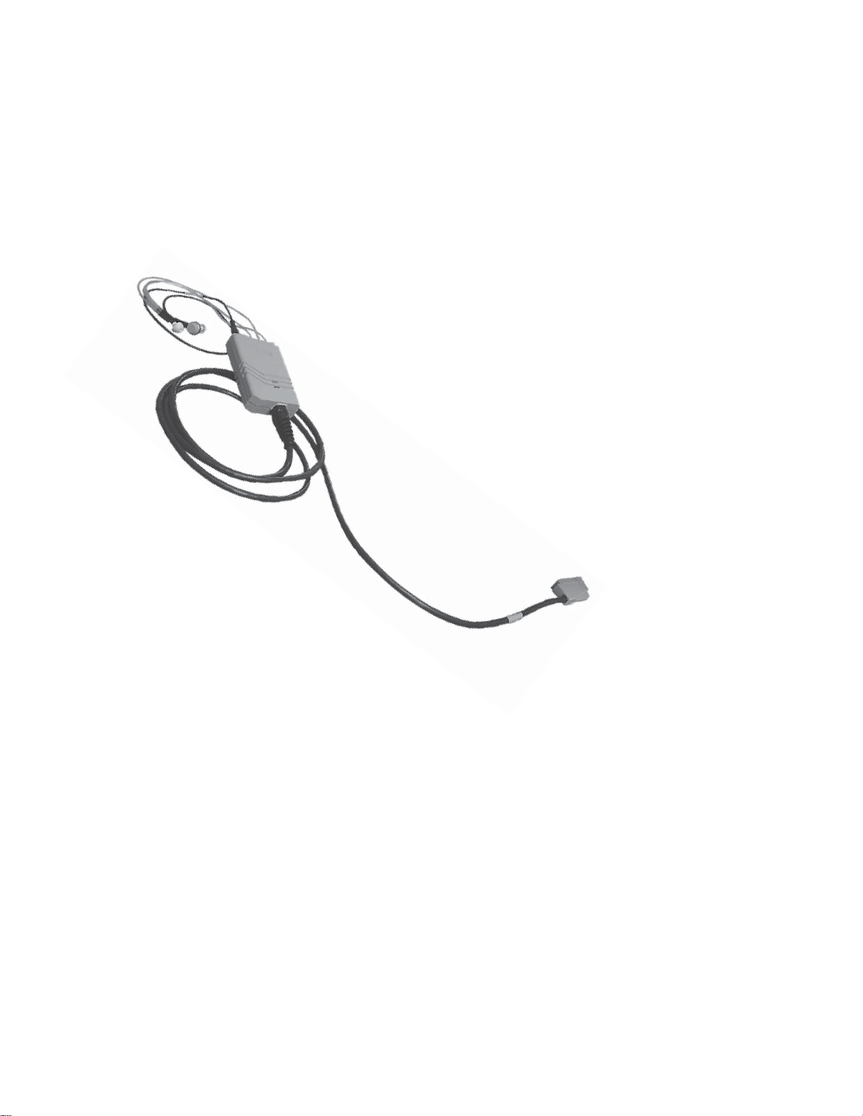
The probe
The innovative lightweight probe is designed for patient comfort, ease-of-seal, and
accurate test results. A wide variety of both standard and special sized eartips are
supplied with the GSI TympStar to hermetically seal the ear canal. In addition, a set
of screening eartips is provided for screening tymp and reflex tests.
The operator has a choice of three mountings to support the probe box; the
standard lightweight shoulder mounting, standard clothes clip, or an optional
operator wrist attachment. The probe box has 2 LEDs to indicate test status.
Within the probe box there are two small loudspeakers, a microphone and a
pressure transducer. One loudspeaker delivers the probe tone to the ear canal,
while the microphone monitors the intensity of the probe tone within the ear canal.
The second loudspeaker delivers the ipsilateral (ipsi) stimuli to the ear canal.
The contralateral (contra) insert phone contains its own loudspeaker. The
pressure within the ear canal can be varied within the range of +400 daPa
to -600 daPa. At no time is it possible to exceed specified maximum
limits. Pressure can be varied automatically or manually and from nega-
tive to positive or from positive to negative values. Pressure within
the ear canal is monitored continuously in order to maintain pressure
accuracy throughout each test sequence.
1 - 4
Grason-Stadler
Page 17
Introduction
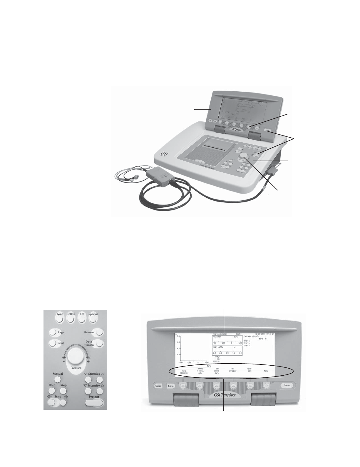
Instrument controls
Hardkeys and softkeys
A combination of hardkeys and softkeys are used to select the test modes and
parameters and to conduct tests.
Hardkeys are located on the front panel and the sides of the LCD panel and provide
fixed functions that do not change. Softkeys are located directly under the LCD and
change to support the requirements of a test session.
LCD panel
Softkey
Hardkeys
Front panel
Pressure control
Rotary pressure
control
Test modes and menu
navigation
Tymp hardkey
A rotary pressure control is also provided to change or fine-tune pressure within the
ear canal.
Selecting a test mode by pressing a hardkey causes the required test screen to be
displayed on the LCD with the appropriate menu of test parameters shown across
the bottom. The softkeys are then used in conjunction with a few hardkeys to
navigate through the menus and set parameter values for the selected tests. For
example, pressing the TYMP hardkey causes the Tymp Diagnostic screen to be
displayed.
Tymp Diagnostic screen
Tymp parameter menu
GSI TympStar Version 1 and Version 2 Service Manual
1 - 5
Page 18
Chapter 1
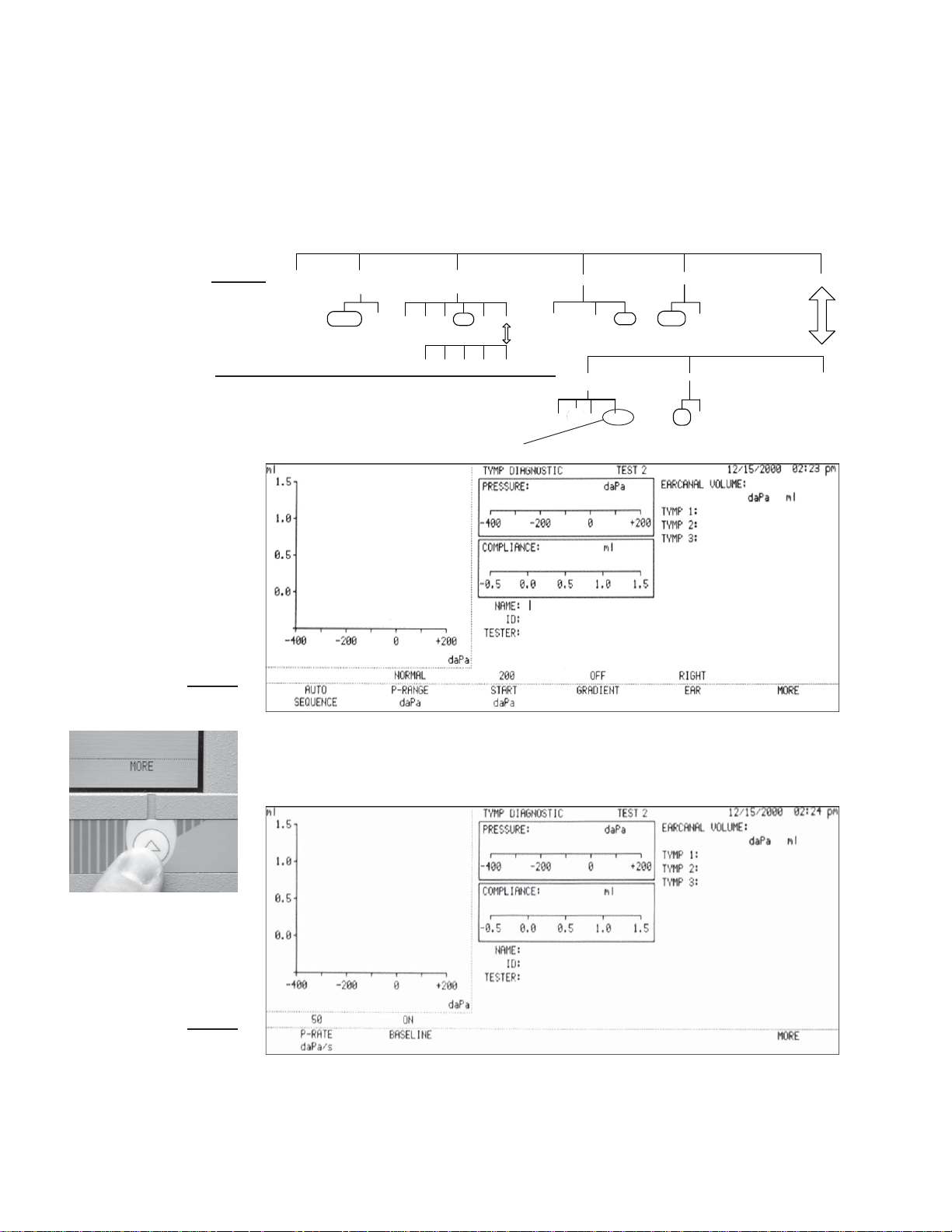
Pressing the softkeys displayed across the bottom of the LCD allows the user to
navigate through the Tymp Diagnostic parameter menus diagrammed below. These
menus are from the Version 1, however, the process is the same in both versions.
GSI default softkey selections are circled on menu diagrams.
The first level of parameter menu selections includes AUTO SEQUENCE,
P-RANGE, START, GRADIENT, EAR and MORE.
First level
Second level
First level
AUTO
SEQUENCE
P-RANGE
daPa
NORMAL WIDE
START
daPa
-600 -400 -200 +200 +400 MORE
-500 -300 0 +300 MORE
Default
selection
GRADIENT
TYMP WIDTH RATIO
daPa ml
P-RATE
daPa/s
12.5 50 200 600/200
OFF
EAR
RIGHT LEFT
BASELINE
ON OFF
MORE
MORE
Second level
1 - 6
A second level of menus can be displayed by pressing the MORE softkey and
includes P-RATE, BASELINE and MORE.
The MORE softkey is used to toggle between the top and lower levels of menus
while the test screen portion above the softkeys remains unchanged.
Grason-Stadler
Page 19

Introduction
Sub-menu of
START daPa
Pressing a parameter menu softkey
causes a sub-menu of parameter
settings to be displayed. Often submenus will also contain MORE
softkey selections that provide access to additional setting alternatives.
Sub-menu of
START daPa
START
daPa
-600 -400 -200 +200 +400 MORE
-500 -300 0 +300 MORE
Changing parameter
settings
Menu diagrams
GSI default parameter settings
Settings can be changed for a selected parameter by pressing the desired softkey as
shown in this example of changing the Probe Hz from 226 to 1000.
Making the new selection returns the display to the previous menu level with the new
setting shown above the selected parameter.
If no change is desired, the display can be returned to the previous level by
pressing the RETURN hardkey.
In the manner described above, menus can be navigated and settings can be
changed for any of the test modes.
Menu structure diagrams like the diagrams shown on these pages will be used
throughout the remainder of this manual as a convenience to the user.
START
GSI default parameters are circled on
menu structure diagrams shown
throughout the remainder of this
manual.
-600 -400 -200 +200 +400 MORE
GSI default value
daPa
-500 -300 0 +300 MORE
GSI TympStar Version 1 and Version 2 Service Manual
1 - 7
Page 20

Chapter 1
1 - 8
Grason-Stadler
Page 21

Specifications
2
Introduction
Detailed specifications are provided in this chapter for the TympStar Version 1
and TympStar Version 2 instruments. The specifications for each instrument
can also be found in its corresponding Reference Instruction Manual.
Version 1 Specifications
Standards
The GSI TympStar Version 1 meets or exceeds the following standards and
specifications for aural acoustic admittance instruments:
IEC 1027 1991-03
ANSI S3.39-1987
ANSI S3.6-1996
ANSI S3.7-1995
IEC 645-1 1992
IEC 126-1973 (also BS 6111-1981)
BS ISO 389-2 1994
Y2K Compliant
UL 2601-1 Part 1: General Requirements for Safety
CSA C22.2 No. 601.1-M90 (Canada)
CE Mark per Medical Device Directive (93/42/EEC)
European Representative:
Mr. Leo Hoogendoorn
Nicolet Biomedical GMBH
Saalackerstrasse 8
63801 Kleinostheim, Germany
Tel: 011-49-6027-46980
Fax: 011-49-6027-469815
EN60601-1:1990 Safety Requirements for Medical Electrical Equipment
EN60601-1-2 Medical Electrical Equipment Emissions and Immunity
Requirements
This equipment has been tested for radio frequency emissions and has been
verified to meet Radiated and Conducted Emissions per EN 55011-1998,
Group 1, Class A and per CISPR, Class A.
GSI TympStar Version 1 and Version 2 Service Manual
2 - 1
Page 22

Chapter 2
Sensitivity ranges
The following admittance measurements give maximum range at 226 Hz, Y
in ml.
Table 1: Tymp Mode
Frequency Digital Read-Out Graphical
Including Cursor Display
226 Hz -7.0 to +7.0 -1.0 to +7.0
Accuracy at 226Hz: 0.1 ml or 5%, whichever is greater.
Table 2: Reflex Mode
Frequency Digital Read-Out Graphical
Including Cursor Display
Probe signal
226 Hz -7.0 to +7.0 -0.16 to +0.80
+0.16 to -0.80
Accuracy: 226 Hz is 0.02 ml or 5%,whichever is greater.
Sinusoidal signal with the following characteristics:
Frequency: 226 Hz
Frequency accuracy: ±1%
Harmonic distortion: <2%
(Measured in an HA-1 2cc coupler)
Signal level: 85 dB SPL
(In Real Ear and in Normal Test Mode)
NOTE
The probe tone level is set to be nominally 70 dB HL.
Signal level accuracy: ±1.5 dB SPL
Grason-Stadler2 - 2
Page 23

Specifications
Pneumatic System
Acoustic Reflex
Activating (Stimulus)
Signal
Pressure Maximum Limits: -800 daPa to +600 daPa
Programmed Pressure Ranges:
Normal: + 200 to - 400 daPa
Wide: + 400 to - 600 daPa
Pressure Accuracy: ±10% or ±10 daPa, Whichever is greater in cavities
from 0.5 cc to 5.0 cc.
Pressure Sweep Rate: 12.5 daPa/sec
50 daPa/sec
600/200 daPa/sec
Manual Sweep Rate Limit: 600 daPa/sec
Sweep Rate Accuracy: ±10%
Pressure System Leak Rate: < 1. 0 daPa/sec
(Measured at -600 and +400 daPa, while pressure servo is disabled.)
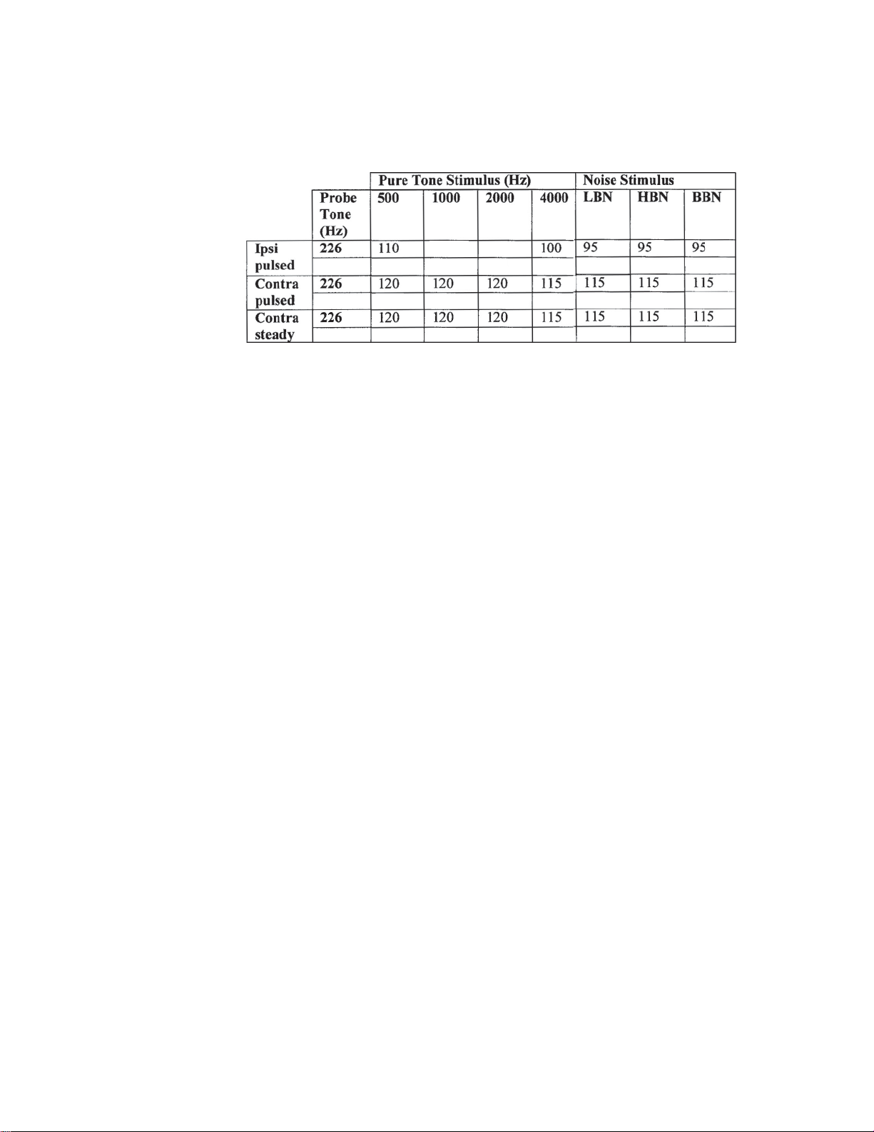
Pure Tone Stimulus
Frequencies for Contra phone and for Ipsi phone with time multiplexed
stimulus. See Table 3.
Frequency Accuracy: ±1%
Total Harmonic Distortion (Acoustically): <2%
(Measured 5 dB HL below guaranteed maximum HL)
Noise Stimulus
The uniformity of the spectrum level of acoustic pressure for the noise signal over 20
averages measured acoustically within their respective band limits will be:
±10 dB for insert or probe type earphones
±5 dB for supra-aural type earphones
Noise Band Widths:
Low Band: 125 -1600 Hz
High Band: 1600 - 4000 Hz
Broad Band: 125 - 4000 Hz (Relative to level at 1 kHz)
Band-edges accurate to within ±15%
Roll off rate: >12 dB/Octave
Stimulus Level Control
Tone Stimulus: The transfer of reference equivalent threshold values are based
on the article; Reference Threshold Levels For The ER-3A Insert Phone, by
Laura Ann Wilber, Barbara A. Krueger and Mead C. Killion, J. Acoustic Soc.
Am. Suppl. 1, Vol. 81 Spring 1987. GSI determined the transfer data from an
IEC 711 coupler to an ANSI HA-1 coupler. Using this data, the reference
threshold values were determined for both the Ipsi and Contra insert earphones
for calibration in an ANSI HA-1 2cc coupler.
Noise Stimulus: The transfer of reference threshold values was done by GSI
using the Threshold Determination Method. The transfer data from an IEC
711 to an ANSI HA- 1 coupler was determined by GSI.
2 - 3GSI TympStar Version 1 and Version 2 Service Manual
Page 24
Chapter 2
Intensity levels are reduced as a function of volume at a rate of 1 dB SPL for each .1
ml. Intensity reduction begins at 1.2 ml.
Table 3: Upper limit of HL range in Reflex Threshold Mode
110
105
Lower limit of HL range for all stimulus signals (35 dB HL).
Hearing Level Increment: 5.0 dB
Hearing Level Increment Accuracy: ±0.5 dB
Hearing Level Control Linearity: ±1.0 dB
Grason-Stadler2 - 4
Page 25

Specifications
Stimulus
Presentation Control
Signal ON/OFF Ratio: >70 dB
OFF mode signal level: <20 dB SPL
Signal To Noise Ratio: >70 dBA
Measured with disabled probe signal and A weighting for noise
measurement.
Residual noise: <25 dBA SPL
(Stimulus Present switch in OFF position)
Unwanted Acoustic Probe Signals: <60 dBA
Measured while pump is operating and probe tone is disabled. Measure it
with A weighted filter in SLOW Time mode. The noise in normal
operating mode will not effect the immittance measurement accuracy.
Signal separation between Ipsi and Contra channels; all frequencies: >70 dB
(Measured at the probes with the ON channel set to 90 dB)
Leaked signal: <20 dB SPL
The radiated acoustic noise from the instrument (with reflex stim off) when
measured at 1 meter from the instrument, shall be: <50 dBA
(A weighting and SLOW averaging)
Temporal Specifications of Stimulus
Presentation
Steady State Stimulus
Initial Delay (elapsed time from present bar activation to 10% stimulus
amplitude): < 100 msec
Terminal Delay (elapsed time from present bar deactivation to 90% stimulus
amplitude): <100 msec
Rise time: 7.5 ± 2.5 msec
Fall time: 7.5 ± 2.5 msec
Multiplexed Stimulus (Used in Reflex Threshold test mode)
Period data for frequencies: 250 and 500 Hz:
Period 124 msec
Stimulus on time 44 msec
Stimulus off time 62 msec
Rise and fall time 18 msec
Period data for all other frequencies:
Period 115 msec
Stimulus on time 44 msec
Stimulus off time 53 msec
Rise and fall time 18 msec
Temporal Spec. Accuracy: ±10% or 5 msec, whichever is greater
2 - 5GSI TympStar Version 1 and Version 2 Service Manual
Page 26

Chapter 2
Environmental
Warm-Up Time
The GSI TympStar Version 1 meets ANSI S3.6-1996 Standards for temperature
and humidity specifications, and it meets the UL 2601-1, CSA 22.2 and IEC606011 standards for safety.
Temperature:
Storage: -40 degrees C to +75 degrees C
Operating: +15 degrees C to +35 degrees C
Humidity: 90% at 35 degrees C (non-condensing)
At room temperature; +15°C to +35°C: 10 Minutes
At room temperature; below +15°C: 1 Hour
Grason-Stadler2 - 6
Page 27
Specifications
Calibration Stability
Connectors
All GSI TympStar Version 1 specifications are met over the range of specified power
line, temperature and humidity variations.
Power Line:
Voltage Variation: ±10%
Frequency Variation: ± 5%
Power line short term variation which affects the performance of the instrument will turn off all probe and stimulus signals.
Power Rating: 120 Watts maximum
Line Voltage Range: 100 VAC to 240 VAC
Power Line Frequency Range: 50 - 60 Hz
Temperature Operating Range: +15°C to +35°C
Relative Humidity Operating Limit: 90%
Guaranteed Operating Elevation: 6000 Ft. (1800m)
STIMULUS: External Stimulus Input
(Phone Jack) Peak Voltage: 3 VAC
Input Impedance: 15,000 Ohms
PRESENT: External Present Control Input that turns the stimulus signal ON
and OFF (Phone Jack).
Voltage Range: STIM OFF: +5.0 VDC
STIM ON: 0.0 v
Input Impedance: 11,000 Ohms
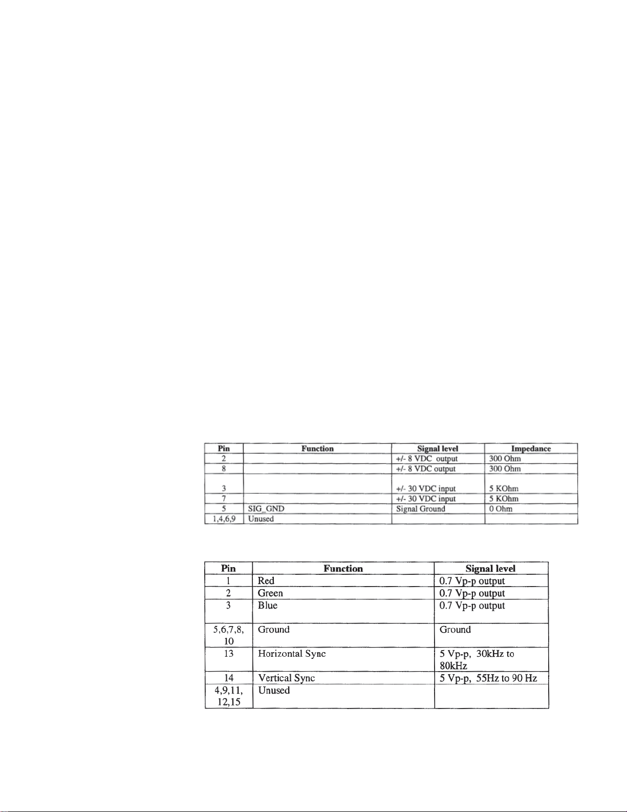
Contra PHONE: Output Voltage: 7 VAC
Output Impedance: 2.5 Ohms
Standard 9-pin RS232C serial port for interfacing with outside computer.
RXD
CTS
TXD
RTS
Standard VGA port for external monitor.
2 - 7GSI TympStar Version 1 and Version 2 Service Manual
Page 28
Chapter 2
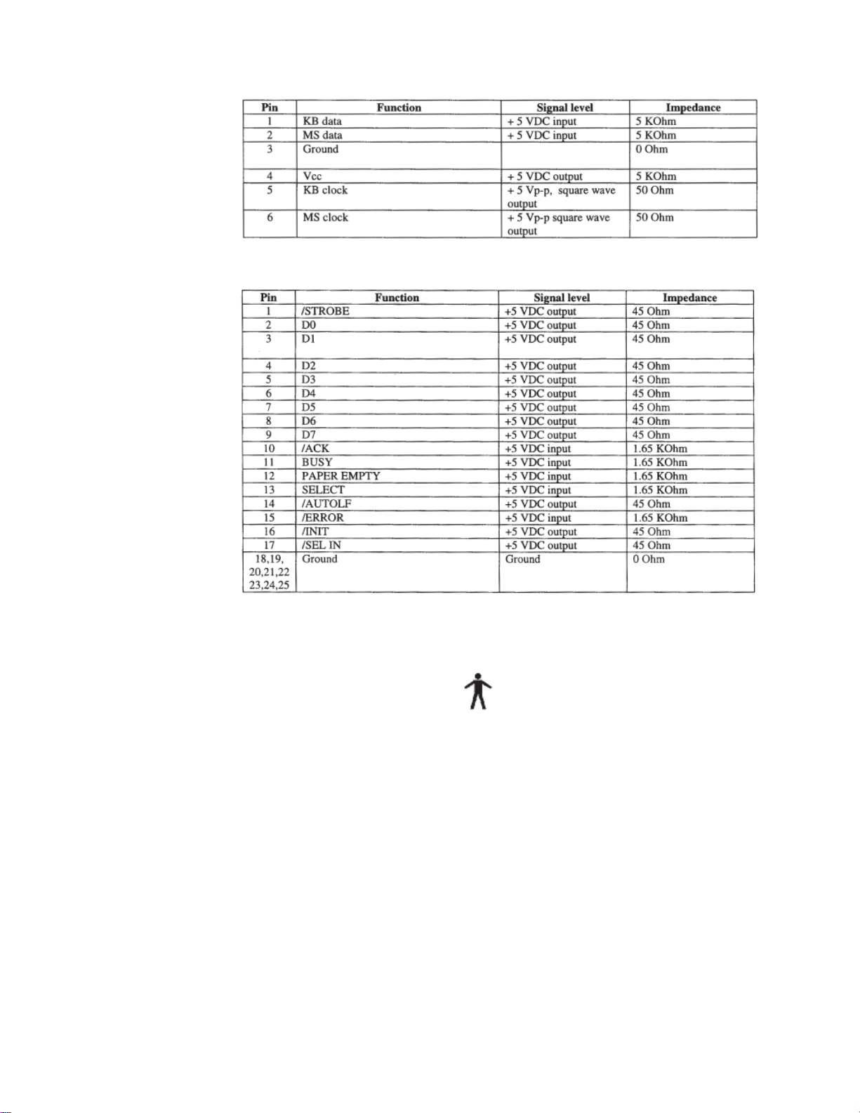
Standard PS-2 keyboard port for external Keyboard.
Standard parallel printer port for external printer.
Electrical
The following apply to the TympStar system:
1) Class 1 Medical Equipment
2) Type B Medical Equipment
3) IPXO ingress of water (ordinary equipment)
4) Equipment not suitable for use in the presence of flammable anesthetic
mixture with air or with oxygen or nitrous oxide.
5) Mode of operation - continuous
Input Voltage: 100 240 VAC
Input Frequency: 50 60 Hz
Input Current: 3.2 A maximum
Power Consumption: 120W maximum
Grason-Stadler2 - 8
Page 29

Specifications
Supplied Accessories
Contra insert phone GSI Part # 8000-0078
Calibration cavity (V1) GSI Part # 2000-1036
Probe cleaning kit (2 boxes) GSI Part # 2000-9610
Eartips:
1 pkg. 8 standard sizes, 4 ea. (Color coded) GSI Part # 1700-9660
1 pkg. 6 special sizes, 2 ea. GSI Part # 1700-9670
1 pkg. 6 screening sizes, 2 ea. GSI Part # 1700-9622
Reference Instruction Manual GSI Part # 2000-0100
Quick User Guide GSI Part # 2000-0108
Printer paper (2 rolls) for orders including printer GSI Part # 1700-9619
Spare set of probe tubing GSI Part # 2000-9617
Probe mount - shoulder GSI Part # 1700-9646
Probe mount - wrist GSI Part # 1700-9642
Probe mount - clothes GSI Part # 1700-9608
Printer paper, adhesive-backed
for orders including a printer GSI Part # 1770-9643
GSI TympStar dustcover GSI Part # 1700-9618
Power cord with hospital-grade plug GSI Part # 4204-0251
(USA)
Power cord part # varies depending on location
Mechanical
Materials of
manufacture
DIMENSIONS AND WEIGHT
W x D x H: 20.38 inches x 15 inches x 12.6 inches (LCD raised)
52cm x 38cm x 32cm
Height with LCD lowered - 6 inches (15cm)
Weight: 16.58 pounds, 7.53 kg
Shipping weight: 29.50 pounds, 13.38 kg
Top Case, LCD Housing
Front & Rear & Hinges: Lexan 500 w/10% Glass & 2% Blowing Agent,
UL 94V0 Rated
LCD Lense: GE HP40S -OR- Duralan II
Switches: Shincor Shin-Etsu/Novacor KE-951 U
Labels: Lexan & Polycarbonate
Softkey Panel: Mylar
Probe Cord: Polyvinyl Chloride (PVC)
Probe Top & Bottom Housings: Cycolac KJW, UL 94V0 Rated
Probe Tip: Polypropolene
Eartips: Kraton 3226
Tubing: Vinyl and Polyurethane
Calibration
requirements
GSI recommends quarterly calibration checks for the GSI TympStar along with
annual certification. ASHA requires quarterly electro-acoustic calibration checks
and annual electro-acoustic calibration. It is good practice to perform daily biologic
checks. See Chapter 4: Calibration for complete calibration instructions.
2 - 9GSI TympStar Version 1 and Version 2 Service Manual
Page 30

Chapter 2
Version 2 Specifications
Standards
The GSI TympStar Version 2 meets or exceeds the following standards and specifications for aural acoustic admittance instruments:
IEC 1027 1991-03
ANSI S3.39-1987
ANSI S3.6-1996
ANSI S3.7-1995
IEC 645-1 1992
IEC 126-1973 (also BS 6111-1981)
BS ISO 389-2- 1994
Y2K Compliant
UL 2601-1 Part 1: General Requirements for Safety
CSA C22.2 No. 601.1-M90 (Canada)
CE Mark per Medical Device Directive (93/42/EEC)
European Representative:
Mr. Leo Hoogendoorn
Nicolet Biomedical GMBH
Saalackerstrasse 8
63801 Kleinostheim, Germany
Tel: 011-49-6027-46980
Fax: 011-49-6027-469815
EN60601-1:1990 Safety Requirements for Medical Electrical Equipment
EN60601-1-2 Medical Electrical Equipment Emissions and Immunity
Requirements
This equipment has been tested for radio frequency emissions and has been
verified to meet Radiated and Conducted Emissions per EN 55011-1998,
Group 1, Class A and per CISPR, Class A.
Grason-Stadler2 - 10
Page 31

Specifications
Sensitivity ranges
The following admittance measurements give maximum range at standard probe
tone frequencies. Compliance Y, 226 Hz is measured in ml. All other units are in
mmhos. (1 acoustic mmho = 10-8 m3) /Pa.s)
Table 1: Tymp Mode (Y, B, G)
Frequency Digital Read-Out Graphical
Including Cursor Display
226 Hz -7.0 to +7.0 -1.0 to +7.0
678 Hz -21 to + 21 -5.0 to +25
1000 Hz -30 to +30 -5.0 to +30
Accuracy:
226Hz: 0.1 ml or 5%, whichever is greater.
Above 226Hz: (F/226) x 0.1 mmho or K% whichever is greater.
K FACTOR: From 250 to 1500 Hz = 5%
Above 1500 Hz =10%
Table 2: Reflex Mode (Y, B, G)
Frequency Digital Read-Out Graphical
Including Cursor Display
226 Hz -7.0 to +7.0 -0.16 to +0.80
+0.16 to -0.80
678 Hz -21 to + 21 -0.48 to +0.80
+0.48 to -0.80
1000 Hz -30 to +30 -0.64 to +0.80
+ 0.64 to -0.80
Accuracy: 226 Hz is 0.02 ml or 5%,whichever is greater.
2 - 11GSI TympStar Version 1 and Version 2 Service Manual
Page 32

Chapter 2
Temporal Latency in
ARLT Mode
Multi Frequency
Probe Signal
(Sinusoidal)
Initial Latency Li: < 5 ± 5 msec.
(From signal onset to 10% of Amplitude)
Terminal Latency Lt: < 5 ± 5 msec
(From signal offset to 90% of Amplitude)
Rise Time Tr: <30 ±5 msec.
(From 10% to 90% of Amplitude)
Fall Time Tt: <25 ±5 msec.
(From 90% to 10% of Amplitude)
Resonant Frequency Measurement Accuracy: 50 Hz or 5%,
Whichever Is Greater
NOTE
Resonant frequency is defined as the frequency at which Delta B is
zero (B is measured at + 200 daPa and at Peak Pressure).
Frequencies:
Discrete: 226 Hz, 678 Hz, 1000 Hz
Multi Freq: From 250 Hz to 2000 Hz
Multi Frequency Increment:50 Hz
Frequency Accuracy:
Discrete and Sweep ±1%
From 250 to 1000 Hz ±1%
Above 1000 Hz ±2%
Harmonic Distortion: <2%
(Measured in an HA-1 2cc Coupler)
Signal Level (In Real Ear and In Normal Test mode):
226 Hz: 85 dB SPL
678 Hz: 80 dB SPL
1000 Hz: 75 dB SPL
NOTE
All Probe Tone levels at all frequencies are set to be nominally 70 dB HL.
Signal Level Accuracy:
226 Hz: ±1.5 dB SPL
Other Frequencies: ±3.0 dB SPL
Grason-Stadler2 - 12
Page 33

Specifications
Pneumatic System
Acoustic Reflex
Activating (Stimulus)
Signal
Pressure Maximum Limits: -800 daPa to +600 daPa
Programmed Pressure Ranges:
Normal: + 200 to - 400 daPa
Wide: + 400 to - 600 daPa
Pressure Accuracy: ±10% or ±10 daPa, Whichever is greater in cavities
from 0.5 cc to 5.0 cc.
Pressure Sweep Rate: 12.5 daPa/sec
50 daPa/sec
600/200 daPa/sec
200 daPa/sec
Manual Sweep Rate Limit: 600 daPa/sec
Sweep Rate Accuracy: ±10%
Pressure System Leak Rate: < 1. 0 daPa/sec
(Measured at -600 and +400 daPa, while pressure servo is disabled.)
Pure Tone Stimulus
Frequencies for Contra phone and for Ipsi phone with time multiplexed
stimulus. See Table 3.
Frequency Accuracy: ±1%
Total Harmonic Distortion (Acoustically): <2%
(Measured 5 dB HL below guaranteed maximum HL)
Noise Stimulus
The uniformity of the spectrum level of acoustic pressure for the noise signal over 20
averages measured acoustically within their respective band limits will be:
±10 dB for insert or probe type earphones
±5 dB for supra-aural type earphones
Noise Band Widths:
Low Band: 125 -1600 Hz
High Band: 1600 - 4000 Hz
Broad Band: 125 - 4000 Hz (Relative to level at 1 kHz)
Band-edges accurate to within ±15%
Roll off rate: >12 dB/Octave
Stimulus Level Control
Tone Stimulus: The transfer of reference equivalent threshold values are based
on the article; Reference Threshold Levels For The ER-3A Insert Phone, by
Laura Ann Wilber, Barbara A. Krueger and Mead C. Killion, J. Acoustic Soc.
Am. Suppl. 1, Vol. 81 Spring 1987. GSI determined the transfer data from an
IEC 711 coupler to an ANSI HA-1 coupler. Using this data, the reference
threshold values were determined for both the Ipsi and Contra insert earphones
for calibration in an ANSI HA-1 2cc coupler.
Noise Stimulus: The transfer of reference threshold values was done by GSI
using the Threshold Determination Method. The transfer data from an IEC
711 to an ANSI HA- 1 coupler was determined by GSI.
2 - 13GSI TympStar Version 1 and Version 2 Service Manual
Page 34

Ipsi
Pulsed
Contra
Pulsed
Contra
Steady
Probe
Tone
226 Hz
678 Hz
1000 Hz
226 Hz
678 Hz
1000 Hz
226 Hz
678 Hz
1000 Hz
Chapter 2
Intensity levels are reduced as a function of volume at a rate of 1 dB SPL for each .1
ml. Intensity reduction begins at 1.2 ml.
Table 3A: Upper limit of HL range in Reflex Threshold Mode
Pure Tone Stimulus (Hz) Noise Stimulus Other Stimulus
250
95
95
95
110
110
110
n/a
110
110
500
110
110
110
120
120
120
120
n/a
120
1000
110
110
110
120
120
120
120
120
n/a
2000
105
105
105
120
120
120
120
120
120
4000
100
100
100
115
115
115
115
115
115
LBN
95
95
95
115
115
115
115
115
115
HBN
95
95
95
115
115
115
115
115
115
BBN
95
95
95
115
115
115
115
115
115
Click
(SPL)
110
110
110
120
120
120
120
120
120
EXT
(SPL)
110
110
110
120
120
120
120
120
120
Lower limit of HL range for all stimulus signals (35 dB HL).
Hearing Level Increment: 1.0, 2.0, 5.0 dB
Hearing Level Increment Accuracy: ±0.5 dB
Hearing Level Control Linearity: ±1.0 dB
Contra
Ipsi
Table 3B: Upper limit of HL range in ARLT and Reflex Decay Modes
Stimulus Selections (Hz) Noise Stimulus Other Stimulus
Probe
Tone
226Hz
678Hz
226Hz
678Hz
1
Limits apply for Reflex Decay and ARLT modes.
2
Limits apply for Reflex Decay only. ARLT not available at 678 Hz.
3
Limits apply for Reflex Decay only. ARLT limit is 105 dB.
250
1
n/a
2
110
1
n/a
2
90
500
120
n/a
105
n/a
1000
120
120
110
110
2000
120
120
3
105
100
4000
115
115
100
100
LBN
115
115
n/a
n/a
HBN
115
115
n/a
n/a
BBN
115
115
n/a
n/a
Click
(SPL)
120
120
n/a
n/a
EXT
(SPL)
120
120
110
110
Grason-Stadler2 - 14
Page 35

Specifications
TABLE 4: UPPER HL LIMIT IN ACOUSTIC REFLEX
SENSITIZATION MODE
Cf Versus l
a
Ipsi Actuator Cf (Contra facilitator)
(Hz) (HL) 500Hz 1000 2000 4000 6000 BBN EXT(SPL)
(dbHL) (dbHL) (dbHL) (dbHL) (dbHL) (dbHL) (dbSPL)
500 105 --- 120 120 115 115 115 120
1000 110 120 --- 120 115 115 115 120
2000 105 120 120 --- 115 115 115 120
4000 100 120 120 120 --- 115 115 120
EXT 101 120 120 120 115 115 115 120
Cf Versus C
a
Contra Actuator Ct (Contra facilitator)
(Hz) (HL) 500Hz 1000 2000 4000 6000 BBN EXT(SPL)
(dbHL) (dbHL) (dbHL) (dbHL) (dbHL) (dbHL) (dbSPL)
500 120 --- 120 120 115 115 115 120
1000 120 120 --- 120 115 115 115 120
2000 120 120 120 --- 115 115 115 120
4000 115 120 120 120 --- 115 115 120
BBN 115 120 120 120 115 115 115 120
EXT 120 120 120 120 115 115 115 120
Cf Versus C
a
Contra Actuator If (Ipsi facilitator)
(Hz) (HL) 500Hz 1000 2000 4000 6000 EXT(SPL)
(dbHL) (dbHL) (dbHL) (dbHL) (dbHL) (dbSPL)
500 120 --- 110 105 100 90 110
1000 120 105 --- 105 100 90 110
2000 120 105 110 --- 100 90 110
4000 115 105 110 105 --- 90 110
BBN 115 105 110 105 100 90 110
EXT 120 105 110 105 100 90 110
If Versus l
a
Ipsi Actuator If (Ipsi facilitator)
(Hz) (HL) 500Hz 1000 2000 4000 6000 EXT(SPL)
(dbHL) (dbHL) (dbHL) (dbHL) (dbHL) (dbSPL)
500 105 --- 110 105 100 90 110
1000 110 105 --- 105 100 90 110
2000 105 105 110 --- 100 90 110
4000 100 105 110 105 --- 90 110
EXT 110 105 110 105 100 90 110
2 - 15GSI TympStar Version 1 and Version 2 Service Manual
Page 36

Chapter 2
Click Stimulus
Guaranteed Peak Equivalent SPL Levels:
Ipsi: 110 dB SPL
Contra: 120 dB SPL
Peak hold SPL to peak equivalent SPL transfer data.
(Peak hold SPL = peak equivalent SPL + transfer data)
Ipsi: 8.5 dB
Contra: 5.5 dB
ClickRate Range: 50-300 Pulse/sec.
Click rate accuracy: ±1pulse/sec.
Pulse Width (Electrically Measured): 100 msec.
Pulse Rise/Fall Time (Electrically): 5.0 msec.
Frequency Spectrum:
Ipsi: 50 - 4000 Hz
Contra: 50 - 3600 Hz
NOTE
Frequency spectrum uniformity better than: 10 dB
External Input: At 0.5 VRMS:
1 KHz Upper Limits:
Ipsi: 110 dB SPL
Contra: 120 dB SPL
Stimulus
Presentation Control
Signal ON/OFF Ratio: >70 dB
OFF mode signal level: <20 dB SPL
Signal To Noise Ratio: >70 dBA
Measured with disabled probe signal and A weighting for noise
measurement.
Residual noise: <25 dBA SPL
(Stimulus Present switch in OFF position)
Unwanted Acoustic Probe Signals: <60 dBA
Measured while pump is operating and probe tone is disabled. Measure it
with A weighted filter in SLOW Time mode. The noise in normal
operating mode will not effect the immittance measurement accuracy.
Signal separation between Ipsi and Contra channels; all frequencies: >70 dB
(Measured at the probes with the ON channel set to 90 dB)
Leaked signal: <20 dB SPL
The radiated acoustic noise from the instrument (with reflex stim off) when
measured at 1 meter from the instrument, shall be: <50 dBA
(A weighting and SLOW averaging)
Grason-Stadler2 - 16
Page 37

Specifications
Temporal Specifications Of Stimulus
Presentation
Steady State Stimulus
Initial Delay (elapsed time from present bar activation to 10% stimulus
amplitude): < 100 msec
Terminal Delay (elapsed time from present bar deactivation to 90% stimulus
amplitude): <100 msec
Rise time: 7.5 ± 2.5 msec
Fall time: 7.5 ± 2.5 msec
NOTE
Initial and terminal delays do not effect temporal measurement of ARLT
test (software compensates for them).
Multiplexed Stimulus (Used in Reflex Threshold test mode)
Period data for frequencies: 250 and 500 Hz:
Period 124 msec
Stimulus on time 44 msec
Stimulus off time 62 msec
Rise and fall time 18 msec
Environmental
Warm-Up Time
Period data for all other frequencies:
Period 115 msec
Stimulus on time 44 msec
Stimulus off time 53 msec
Rise and fall time 18 msec
Temporal Spec. Accuracy: ±10% or 5 msec, whichever is greater
The GSI TympStar Version 2 meets ANSI S3.6-1996 (Rl986) Standards for temperature and humidity specifications, and it meets the UL 2601 Standards
in terms of shock hazards and leakage.
Temperature:
Storage: -40 degrees C to +75 degrees C
Operating: +15 degrees C to +35 degrees C
Humidity: 90% at 35 degrees C (non-condensing)
At room temperature; +15°C to +35°C: 10 Minutes
At room temperature; below +15°C: 1 Hour
2 - 17GSI TympStar Version 1 and Version 2 Service Manual
Page 38

Chapter 2
Calibration Stability
Connectors
All GSI TympStar Version 2 specifications are met over the range of specified power
line, temperature and humidity variations.
Power Line:
Voltage Variation: ±10%
Frequency Variation: ± 5%
Power line short term variation which affects the performance of the instrument will turn off all probe and stimulus signals.
Power Rating: 120 Watts maximum
Line Voltage Range: 100 VAC to 240 VAC
Power Line Frequency Range: 50 - 60 Hz
Temperature Operating Range: +15°C to +35°C
Relative Humidity Operating Limit: 90%
Guaranteed Operating Elevation: 6000 Ft. (1800m)
STIMULUS: External Stimulus Input
(Phone Jack) Peak Voltage: 3 VAC
Input Impedance: 15,000 Ohms
PRESENT: External Present Control Input that turns the stimulus signal ON
and OFF (Phone Jack).
Voltage Range: STIM OFF: +5.0 VDC
STIM ON: 0.0 v
Input Impedance: 11,000 Ohms
Contra PHONE: Output Voltage: 7 VAC
Output Impedance: 2.5 Ohms
Standard 9-pin RS232C serial port for interfacing with outside computer.
RXD
CTS
TXD
RTS
Standard VGA port for external monitor.
Grason-Stadler2 - 18
Page 39

Specifications
Standard PS-2 keyboard port for external Keyboard.
Standard parallel printer port for external printer.
Electrical
The following apply to the TympStar system:
1) Class 1 Medical Equipment
2) Type B Medical Equipment
3) IPXO ingress of water (ordinary equipment)
4) Equipment not suitable for use in the presence of flammable anesthetic
mixture with air or with oxygen or nitrous oxide.
5) Mode of operation - continuous
Input Voltage: 100 240 VAC
Input Frequency: 50 60 Hz
Input Current: 3.2 A maximum
Power Consumption: 120W maximum
2 - 19GSI TympStar Version 1 and Version 2 Service Manual
Page 40

Chapter 2
Supplied Accessories
Contra insert phone GSI Part # 8000-0078
Calibration cavity (V2) GSI Part # 2000-1035
Probe cleaning wire (2 boxes) GSI Part # 2000-9610
Eartips:
1 pkg. 8 standard sizes, 4 ea. (Color coded) GSI Part # 1700-9660
1 pkg. 6 special sizes, 2 ea. GSI Part # 1700-9670
1 pkg. 6 screening sizes, 2 ea. GSI Part # 1700-9622
Reference Instruction Manual GSI Part # 2000-0120
Quick User Guide GSI Part # 2000-0126
Printer paper (2 rolls) for orders including printer GSI Part # 1738-9619
Spare set of probe tubing GSI Part # 2000-9617
Probe mount - shoulder GSI Part # 1700-9646
Probe mount - wrist GSI Part # 1700-9642
Probe mount - clothes GSI Part # 1700-9608
Printer paper, adhesive-backed
for orders including a printer GSI Part # 1770-9643
GSI TympStar dustcover GSI Part # 1700-9618
Power cord with hospital-grade plug GSI Part # 4204-0251
(USA)
Power cord part # varies depending on location
Mechanical
Materials of
manufacture
DIMENSIONS AND WEIGHT
W x D x H: 20.38 inches x 15 inches x 12.6 inches (LCD raised)
52cm x 38cm x 32cm
Height with LCD lowered - 6 inches (15cm)
Weight: 16.58 pounds, 7.53 kg
Shipping weight: 29.50 pounds, 13.38 kg
Top Case, LCD Housing
Front & Rear & Hinges: Lexan 500 w/10% Glass & 2% Blowing Agent,
UL 94V0 Rated
LCD Lense: GE HP40S -OR- Duralan II
Switches: Shincor Shin-Etsu/Novacor KE-951 U
Labels: Lexan & Polycarbonate
Softkey Panel: Mylar
Probe Cord: Polyvinyl Chloride (PVC)
Probe Top & Bottom Housings: Cycolac KJW, UL 94V0 Rated
Probe Tip: Polypropolene
Eartips: Kraton 3226
Tubing: Vinyl and Polyurethane
Calibration
requirements
GSI recommends quarterly calibration checks for the GSI TympStar along with
annual certification. ASHA requires quarterly electro-acoustic calibration checks
and annual electro-acoustic calibration. It is good practice to perform daily biologic
checks. See Chapter 4: Calibration for complete calibration instructions.
Grason-Stadler2 - 20
Page 41

Operation summary
This chapter summarizes the operation of the TympStar Verrsion 1 and TympStar
Version 2 Middle-ear Analyzers. A brief introduction to the TympStar controls, menus and LCD screens will be followed by summarized test procedures
for each instrument. Please refer to the Reference Instruction Manuals for
more detailed operating instructions.
NOTE
Most generic LCD screen and menu examples use TympStar Version 2
images. However, the concepts and processes described apply equally
well to both instruments.
Front panel controls
Front panel controls consist of a combination of hardkeys with fixed functions that
do not change, and softkeys located under the LCD that change to support the
changing requirements of a test session. A rotary pressure control is provided to
change or fine-tune pressure within the ear canal.
3
LCD housing
Softkey
Front panel
Pressure control
Hardkey
3 - 1GSI TympStar Version 1 and Version 2 Service Manual
Page 42

Chapter 3
Hardkeys
Tymp
Reflex
Etf
All of the push-button controls on the
front panel are hardkeys. Three hardkeys are also located on the left and
right sides of the LCD housing. Their
functions are printed directly on the
push-button or nearby on the panel
and do not change. The front panel
hardkey functions include:
Causes GSI (or operator programmed) default criteria for diagnostic tymp test to be automatically set
up.
Causes GSI (or operator programmed) default criteria for reflex
threshold testing to be automatically
set up.
Causes GSI (or operator programmed) default criteria for eustachian tube function (intact eardrum) test to be automatically set up.
Special
Page
Print
Remote
Data Transfer
Pressure control
Manual
Hold
Causes GSI TympStar to initialize to GSI (or operator programmed) default
criteria for reflex decay test.
Allows operator to recall and display tests in memory or in progress.
Allows operator to print selected test results.
Used when GSI TympStar is interfaced with external computer. Implements a
common handshake routine to ensure that the RS232 link is in place.
Used to send test data to an external computer.
Rotary knob used to manually change or fine-tune the pressure within the ear
canal.
Allows the user to run each applicable test procedure manually. The pressure
control is used to change pressure manually within the ear canal.
Allows the current test sequence to be temporarily halted without venting the
ear canal pressure.
Stop
3 - 2
Allows the current test sequence to be terminated. The ear canal is vented.
Data on the current page is stored in memory.
Grason-Stadler
Page 43

Operation Summary
Start
Stimulus
Intensity
Present
LCD hardkeys
Clear
Erase
Return
Causes the selected test sequence to begin in the direction indicated by the associated arrow.
Allows available stimuli to be scrolled up or down and selected. This feature
is available only for Reflex type tests.
Allows operator to select and set desired intensity (dB HL). This feature is
available only for Reflex type tests.
Allows selected stimulus to be presented either manually or according to preset automatic timing. This feature is available only for Reflex type tests.
Three hardkeys are also located on the left and right sides of the LCD housing.
Their functions are printed directly on the push-button and do not change. The
LCD housing hardkey functions include:
Deletes selected tests stored in memory.
Erases current display of test results prior to placing test results in memory.
Allows the operator to go back to the next higher level in the softkey menu.
Depressing Return while in Clear, Page, or Print mode restores the instrument
to the mode previously selected.
Softkeys
The push-buttons located directly under the LCD are the only softkeys. Their
functions are displayed on the LCD and change in support of the current test
activities.
Test parameters
Test parameter softkeys
GSI TympStar Version 1 and Version 2 Service Manual
3 - 3
Page 44

Chapter 3
Menus and LCD screens
Hardkeys are located on the front panel and the sides of the LCD panel and
provide fixed functions that do not change, such as selection of test type.
Softkeys located directly under the LCD change to support the requirements
of each test session.
Test parameters
Menus
Test parameter softkeys
Selecting a test mode by pressing a hardkey causes the required test screen to be
displayed with the appropriate menu of test parameters shown across the bottom of
the LCD. The softkeys are then used in conjunction with a few hardkeys to navigate
through menus and set parameter values for the selected tests. For example, pressing the TYMP hardkey causes the Tymp Diagnostic screen to be displayed.
GSI-developed default parameters for each selected test are displayed on the
lower portion of the LCD above the six softkeys. Alternative choices may be
made by pressing the appropriate test parameter softkey.
Pressing a test parameter softkey causes a new menu of choices to be presented across the bottom of the screen for that function. The menu structure
for the TympStar Version 2 Tymp diagnostic functions is diagrammed on the
next page as an example.
3 - 4
Grason-Stadler
Page 45

Operation Summary
AUTO
SEQUENCE
226 678 1000
P-RATE
daPa/s
12.5 50 200 600/200
GSI default
parameter
Program modes
PROBE
Hz
-600 -400 -200 +200 +400 MORE
-500 -300 0 +300 MORE
ADMITTANCE
Y B G B/G
ml mmho mmho mmho
START
daPa
The MORE softkey is used to toggle between the top and lower levels of menus
while the test screen portion above the softkeys remains unchanged.
NOTE
The GSI default parameters are circled on the menu structure diagrams.
All test modes allow the user to individually program a unique set of default
test parameters. User-programmed parameters override GSI-developed default parameters.
P-RANGE
daPa
NORMAL WIDE
BASELINE
ON OFF TYMP WIDTH RATIO
GRADIENT
daPa ml
EAR
RIGHT LEFT
OFF
MORE
CURSOR
OFF TYMP 1 TYMP 2 TYMP 3
SET PEAK SET PEAK SET PEAK
MORE
Version 1 probe tone
frequencies
Version 2 probe tone
frequencies
Version 1 LCD
graphic traces
Version 2 LCD
graphic traces
The TympStar Version 1 measures compliance using a 226 Hz probe tone.
The following probe tone frequencies are available:
226 Hz - All Tests
678 Hz - Tymp Diagnostic, Reflex Threshold, Reflex Decay, ETF
1000 Hz - Tymp Diagnostic, Reflex Threshold, ETF
250 Hz - 2000 Hz Sweep - Multiple Frequency Tympanometry
The TympStar Version 1 measures compliance, and shows the tracing on the
graphic display as a solid line.
The TympStar Version 2 measures admittance (Y), and its components:
Susceptance (B) and Conductance (G). Admittance (Y) and Susceptance (B)
tracings are solid lines, while tracings of conductance (G) values are dotted
lines.
GSI TympStar Version 1 and Version 2 Service Manual
3 - 5
Page 46

Chapter 3
Probe lights
LCD screen
Lights are provided on the probe to indicate test status in the following
manner:
Solid Green = Test In Progress
Solid Amber = Occlusion
Blinking Amber = Leak
Blinking Green = OK to begin a test
Probe lights
The liquid crystal display (LCD) shows axes for the graphic display of the
selected test, and pressure and compliance or admittance meters.
3 - 6
THE TEST STATUS line to the right of the graphics area of screen displays alert
messages, invalid selections, and other messages to user.
Test Status Line
Test tracings, meter displays with digital readouts, and ear canal volume are recorded in real time.
Grason-Stadler
Page 47

Operation Summary
Erasing and clearing
test data
CLEAR hardkey
ERASE hardkey
The display of current test data may be erased prior to stopping a test or continuing
to the next test by pressing the ERASE hardkey. Previous test data can be selectively cleared from the instruments storage by selecting the desired test with the
PAGE hardkey, then pressing the CLEAR hardkey
PAGE hardkey
PRINT hardkey
It is suggested that all testing be completed on one ear before proceeding to the
other ear. Changing the test ear causes a new page of test data to be generated.
Version 2 External
reflex test stimuli
External reflex test stimuli
Paging test data
Reflex test stimuli may be input from an external source and presented via
external control. The connections for these external inputs are provided on the
rear panel of the Version 2 instrument. These jacks are unused in the TympStar
Version 1.
input
External present control
input
Up to 26 test screens can be stored in memory as pages. These pages of data can
be recalled with appropriate titles and labels for viewing by pressing the PAGE
hardkey, then scrolling through pages using up/down arrows. Each screen of data
equals a page.
GSI TympStar Version 1 and Version 2 Service Manual
3 - 7
Page 48

Chapter 3
Version 2 cursor
A cursor is available in the TympStar Version 2 on all test data pages for scrolling left
or right on the graphics area and can be used to set or reset tymp peak values for
tests. A cursor box describes the numeric position of the cursor on both the X and
Y axes. Cursors are not available in the Version 1.
Cursor Cursor box
NOTE
The cursor must be used to set tymp values when testing at anything other
than 226Hz, Y in the Version 2.
Printing tests
Preparing an external
printer
Up to 26 test screens stored in memory can be printed by selecting PAGE-ALL
followed by PRINT. Individual test results can be printed by selecting PAGE
and then using the arrow key to display the test. To begin printing, press the
PRINT hardkey.
The TympStar supports the full line of Hewlett Packard DeskJet® and LaserJet
printers. These printers provide full sheet printouts of test data. A test printout
of results containing:
One left and right tympanogram graph
A reflex threshold table for both left and right (Ipsi or Contra only)
A reflex decay table for both left and right (Ipsi or Contra only)
will print on one 8.5 x 11 inch sheet of paper.
1) Turn the TympStar and printer off, then attach the printer data cable to the
printer connector on the rear of the TympStar. Connect the printer power
cable to AC power.
WARNING
ANY EQUIPMENT CONNECTED TO THE GSI TYMPSTAR AND
USED IN THE PATIENT VICINITY MUST BE POWERED BY AN ISOLATED POWER SOURCE TO MAINTAIN THE ELECTRICAL
SAFETY OF THE OVERALL SYSTEM. The isolated power source can
be purchased directly from GSI, or elsewhere when approved for use by
GSI.
®
3 - 8
Grason-Stadler
Page 49

Operation Summary
2) Turn the TympStar and printer on. Anytime the external printer is connected
and turned on, the TympStar will automatically direct printing to the external
printer. To redirect printing to the internal printer, turn the external printer off or
disconnect it.
Setting the printer
parameters
To set the external printer parameters:
1) Press the ETF hardkey to select the
ETF test mode, then press the RETURN
hardkey to display the ETF sub-menu.
2) Press the INSTRUMENT OPTIONS
INTACT
TM
PERF
TM
INSTRUMENT
OPTIONS
PROGRAM
MODE
softkey, then the MORE softkey to display the PRINT FORMAT softkey selection.
3) Press the PRINT FORMAT softkey, and then the MORE softkey to display the
EXTERNAL PRINTER SETUP softkey selection.
GSI TympStar Version 1 and Version 2 Service Manual
3 - 9
Page 50

Chapter 3
4) Press the EXTERNAL PRINTER SETUP softkey to display the External Printer
Setup Menu.
Left column printout
data
Color or black and
white
5) Press the LEFT COLUMN SETTING softkey of the External Printer Setup
Menu to set the left column of the printed data to the left or right ear.
6) Press the PRINT TYPE softkey of the External Printer Setup Menu to set the
printout to Black and White or Color.
3 - 10
NOTE
The setting must be Black and White for grayscale printers.
Grason-Stadler
Page 51

Operation Summary
Changing Instrument Versions
Changing from a
Version 2 to a
Version 1
The Version function provides an easy way for a TympStar Version 2 to be
changed to a Version 1 instrument either temporarily or permanently. Version
1 functionality is a limited subset of Version 2 functionality and does not include 678 and 1000 Hz probe tones, multi-frequency tympanometry or ARLT
testing.
To change from a TympStar Version 2 to a
Version 1:
1) Press the ETF hardkey to select the
ETF test mode, then press the RETURN hardkey to display the ETF submenu.
INTACT
TM
PERF
TM
INSTRUMENT
OPTIONS
PROGRAM
MODE
2) Press the INSTRUMENT OPTIONS softkey, then the MORE softkey to display the VERSION softkey selection.
GSI TympStar Version 1 and Version 2 Service Manual
3 - 11
Page 52

Chapter 3
3) Press the VERSION softkey to display the Version Menu.
NOTE
To return to the Instrument Options menu with no version switching action
taken, press the RETURN hardkey from the Version menu.
Switching to V1
temporarily
Switching back to V2
Switching to V1
permanently
1) Press the V1 TEMPORARY softkey to change the instrument to V1 functionality temporarily. The message: SWITCHING TO A V1 INSTRUMENT. WAITING FOR WARMSTART will appear. The system will
then reboot and reinitialize as a TympStar Version 1.
The V1 Temporary mode allows the instrument to be switched back to V2
mode. The instrument will stay in V1 Temporary mode indefinitely, until
changed back to V2 mode as described below.
1) Press the V2 softkey in the Version Menu. Lock and key codes are displayed on the screen.
NOTE
Press the CONTINUE softkey from this screen to keep the TympStar in
the V1 Temporary mode.
2) Press the DATA TRANSFER hardkey. The message: SWITCHING TO A
V2 INSTRUMENT. WAITING FOR WARMSTART will appear. The
system will then reboots and reinitialize as a TympStar Version 2.
1) Press the V1 PERMANENT softkey in the Version Menu to change the
instrument to V1 functionality permanently. The message: ARE YOU
SURE YOU WANT TO CHANGE THIS TO A V1 INSTRUMENT? will
appear.
3 - 12
CAUTION
Once an instrument is changed to V1 permanently it cannot be changed
back to V2 without a license key from Grason-Stadler.
Grason-Stadler
Page 53

Operation Summary
2) Press the YES softkey to switch the TympStar to a V1 instrument permanently.
The message: SWITCHING TO A V1 INSTRUMENT. WAITING FOR
WARMSTART will appear. The system will then reboot and reinitialize as a
TympStar Version 1.
Changing from a
Version 1 to a
Version 2
The Version function provides an easy way for a TympStar Version 1 to be
upgraded to a Version 2 instrument. Version 2 functionality provides expanded testing capability and includes 678 and 1000 Hz probe tones, multifrequency tympanometry and ARLT testing. A license code must be obtained
from Grason-Stadler. to upgrade a TympStar Version 1 to a Version 2.
To change from a TympStar Version 1 to a Version 2:
1) Press the ETF hardkey to select the
ETF test mode, then press the RETURN
hardkey to display the ETF sub-menu.
2) Press the INSTRUMENT OPTIONS
INTACT
TM
PERF
TM
INSTRUMENT
OPTIONS
PROGRAM
MODE
softkey, then the MORE softkey to display the VERSION softkey selection.
GSI TympStar Version 1 and Version 2 Service Manual
3 - 13
Page 54

Chapter 3
3) Press the VERSION softkey to display the Version Menu.
Obtaining a License
Code
NOTE
To return to the Instrument Options menu with no version switching action
taken, press the RETURN hardkey from the Version menu.
4) Press the V2 softkey. The following messages will appear:
YOU MUST OBTAIN A LICENSE KEY TO LAUNCH V2 TYMPSTAR
CONTACT YOUR GSI REPRESENTATIVE WITH THE FOLLOWING
CODE:
0A2B3C4E5D (example of lock code)
YOUR GSI REPRESENTATIVE WILL PROVIDE YOU WITH A LICENSE
KEY CODE.
ENTER THE LICENSE KEY CODE HERE:
THEN PRESS THE DATA TRANSFER KEY
5) Press the PRINT hardkey to print out the lock code. Contact your GSI representative with the lock code. If a V2 upgrade is purchased, you will be provided with a license key code and V2 probe. Once you have received the V2
3 - 14
Grason-Stadler
Page 55

Operation Summary
license key and probe, follow the instructions below to change the TympStar to
V2 functionality.
NOTE
Press the CONTINUE softkey from this screen to keep the TympStar in V1
mode.
Replacing the V1
Probe with a V2
Probe
To replace the TympStar probe:
WARNING
Turn off power to the TympStar.
1) Disconnect the air tubing to the brass fitting on the side of the TympStar.
2) Remove the cable clamp on the side of
the TympStar
3) Remove the two retaining screws that secure the probe connector to the TympStar.
4) Pull the connector straight out and away from the side of the TympStar chassis.
Reverse this sequence to connect the new Version 2 probe to the TympStar. Contact your GSI representative to have the removed probe returned to GSI.
5) Connect an external keyboard, power the instrument and return to the
VERSION sceen.
GSI TympStar Version 1 and Version 2 Service Manual
3 - 15
Page 56

Chapter 3
Switching to
Version 2 software
1) Press the V2 softkey from the Version menu. The following messages will appear:
YOU MUST OBTAIN A LICENSE KEY TO LAUNCH V2 TYMPSTAR
CONTACT YOUR GSI REPRESENTATIVE WITH THE FOLLOWING CODE:
0A2B3C4E5D (example of lock code)
YOUR GSI REPRESENTATIVE WILL PROVIDE YOU WITH A LICENSE
KEY CODE.
ENTER THE LICENSE KEY CODE HERE:
THEN PRESS THE DATA TRANSFER KEY
Using an external keyboard, type in the license key code as indicated by the
on-screen instructions. Press the DATA TRANSFER hardkey. The message:
SWITCHING TO A V2 INSTRUMENT. WAITING FOR WARMSTART will
appear. The system will then reboot and reinitialize as a V2 TympStar.
3 - 16
Grason-Stadler
Page 57

Operation Summary
Version 1 test procedures
The following TympStar Version 1 test procedures are summarized. Comprehensive procedures are provided in the TympStar Version 1 Reference Instruction Manual.
Tymp diagnostic
Manual Tymp
1) Select test mode by turning POWER ON, or by pressing TYMP
hardkey. Default test parameters are displayed above softkeys on the
LCD.
2) Attach the probe box to the velcro strip on the shoulder probe mount.
3) Position the shoulder probe mount on the patient.
4) Position the appropriate size eartip on the probe tip and securely insert into
the ear canal.
5) Press EAR softkey, then select LEFT or RIGHT ear.
6) Press START hardkey to initiate test.
7) View ongoing test results on the graphic display area, and on the pressure
and compliance meters.
8) Press the STOP hardkey to end the test, store the results in memory, and
display the summary data on the screen.
NOTE
A MANUAL TYMP test may be initiated by pressing the MANUAL hardkey. Rotate the PRESSURE KNOB to vary pressure and view ongoing
test results graphically, or on the pressure and compliance meters.
1) Securely insert the probe tip within the patients ear canal and press the
TYMP hardkey.
2) Press the EAR softkey and select the right or left ear.
3) Press the MANUAL hardkey to pressurize the ear canal to the
previously selected start pressure. Manual mode will appear below the
Name, ID and Tester Information on the display.
4) Use the PRESSURE CONTROL knob to vary the pressure within the
ear canal and control the speed of the tympanometric test.
5) View test results on the display along with the pressure and compliance
meters. Test summary information is displayed to the right of the meters
for the two most recent pressure sweeps.
NOTE
The ERASE hardkey can be used to delete test data prior to pressing the
STOP hardkey.
6) Press the STOP hardkey to store the last two tracings in memory.
7) Press the PAGE hardkey to view test results.
8) Press the PRINT hardkey while in the PAGE mode for printed tests.
MANUAL will appear on the printout indicating a manual test.
GSI TympStar Version 1 and Version 2 Service Manual
3 - 17
Page 58

Chapter 3
Tymp screening
1) Enter test mode by pressing TYMP followed by RETURN. Press the
SCREEN softkey. Test will automatically start once a seal is detected.
2) Default test parameters are displayed above softkeys on the LCD.
3) Attach the probe box to the velcro strip on the shoulder probe mount or to
the wristband probe mount.
4) Press the EAR softkey, then press LEFT or RIGHT ear.
5) Position the appropriate size SCREENING eartip on probe tip.
6) With the hand-held probe, obtain a seal at entrance to ear canal.
Probe lights indicate the following:
Solid Green = Test In Progress
Solid Amber = Occlusion
Blinking Amber = Leak
Blinking Green = OK To Begin A Test
7) Test will start automatically if ear canal seal is good. Screening IPSI
Reflex test at 1 kHz will follow tymp.
8) A Test Complete Remove Probe message will appear on the display
when the test is complete.
9) View test results on the graphic display area along with summary data at
the right of the pressure and compliance meters.
Reflex threshold
Automatic Auto Zero
1) Select test mode by pressing the REFLEX hardkey. Default test parameters are displayed above softkeys on the LCD.
NOTE
AUTO ZERO is used to baseline compliance.
2) Press the START hardkey to pressurize the ear to dynamic peak pressure
maintained from the last Tymp, or to 0 daPa if no previous Tymp data is
available. Pressure control is active for fine-tuning pressure if Tymp is
sharply sloped.
3) Select intensity of stimulus by pressing the INTENSITY up and down
arrow hardkeys.
4) Present auto-timed stimulus by momentarily pressing the PRESENT bar.
5) Press the ERASE hardkey to erase sub-threshold presentations or unwanted
data (i.e. amplitudes of less than 0.02).
6) Press the CONTINUE softkey to allow reflex tracings to continue on next
line of reflex screen and onto the next page in memory.
7) Use the STIMULUS up and down arrow hardkeys to select alternative
test stimuli.
Auto Zero is used to baseline admittance prior to or between stimulus presentations when performing acoustic Reflex Threshold, Reflex Decay, Acoustic
Reflex Latency and Acoustic Reflex Sensitization tests.
3 - 18
Grason-Stadler
Page 59

Operation Summary
Before pressing START, select the AUTO ZERO softkey followed by the AUTOMATIC softkey to activate this feature. The Admittance meter will automatically be
zeroed each time the PRESENT bar is pressed.
The Admittance meter may be zeroed manually after pressing START by pressing the AUTO ZERO softkey as frequently as needed.
Mark Threshold
Reflex Threshold
Seeking
Often multiple tracings are obtained per stimulus presentation, but only one
represents the reflex threshold. Mark Threshold allows the operator to scroll
across each line of data and select the intensity value determined to be the threshold.
1) Select the MARK THRESHOLD softkey.
2) Select the softkey to move the cursor.
3) Press the MARK LINE 1 or MARK LINE 2 softkey to display the
threshold marker (an asterisk).
4) Press the NR LINE 1 or NR LINE 2 softkey to display no response
(NR).
5) Select EXIT softkey to return to the reflex threshold diagnostic menu.
Threshold Seek automates the sequence of button presses used to arrive at
reflex threshold values and also automates the marking of reflex threshold
values.
NOTE
Threshold Seek should only be used with quiet, cooperative patients.
1) Select test mode by depressing REFLEX. Default test parameters are
displayed above softkeys on the LCD.
2) Press the THRESHOLD SEEK softkey.
3) Press ON or CONFIGURE to change test parameters.
4) Press START to pressure ear to dynamic peak pressure maintained from
last tymp, or to 0 daPa if no previous tymp data is available.
5) Present auto timed stimulus by momentarily depressing the PRESENT
bar.
6) Press ERASE to erase unwanted data.
7) Select the CONTINUE softkey to allow reflex tracing to continue on the
next line on the reflex screen.
NOTE
MANUAL REFLEX testing may be performed by pressing MANUAL and
viewing responses to stimuli presentations on the compliance meter.
GSI TympStar Version 1 and Version 2 Service Manual
3 - 19
Page 60

Chapter 3
Reflex decay
1) Select test mode by pressing SPECIAL hardkey. Default test
parameters are displayed above softkeys on the LCD.
NOTE
Alternative sensitivities for displayed reflex response may be selected by
pressing ml SCALE softkey.
2) Dotted vertical lines are displayed above the X-axis of each graph marking
5 sec. and 10 sec. points.
3) Pressure is automatically maintained at the pressure of the last reflex
threshold test. PRESSURE CONTROL is active for fine-tuning pressure.
4) Set the intensity of stimulus to 10 dB HL above the reflex threshold using
the INTENSITY up and down arrow hardkeys.
5) Present stimulus by pressing the PRESENT bar momentarily.
NOTE
Summary data indicates the time at which 50% decay occurred, if appropriate.
6) Additional frequencies may be selected for testing using the STIMULUS
up and down arrow hardkeys. (500 Hz and 1000 Hz are the best
frequencies for this test.)
7) Press the STOP hardkey to end the reflex decay test and store current screen
data in memory.
Eustachian tube
function
Pressure Swallow Test (intact TM)
1) Select test mode by pressing ETF. Default test parameters for ETFINTACT TM are displayed above softkeys on the LCD.
2) Press START to initiate automated test (TYMP 1).
3) View ongoing test results as shown on the graphic display area, or pressure
compliance admittance meters.
4) Press HOLD when the desired pressure sweep limit is reached.
5) Follow the user directions displayed on status line of LCD prior to
obtaining TYMP 2 results using the CONTINUE softkey.
6) Press HOLD when the desired pressure sweep limit for TYMP 2 is reached.
7) Follow the user directions displayed on status line of LCD prior to
obtaining TYMP 3 results using the CONTINUE softkey.
8) Press STOP when the desired pressure sweep limit for TYMP 3 is reached.
9) If the Eustachian tube is functioning properly, view the shift in pressure
peaks of TYMPS 2 and 3 relative to TYMP 1 on the graphic display area.
Numeric summary data is displayed at the right of the compliance/
admittance meter.
Perforated Ear Test (Perforated TM)
1) Select ETF-Perforated TM by pressing ETF (if not already pressed) and
RETURN followed by the PERF TM softkey.
3 - 20
Grason-Stadler
Page 61

Operation Summary
2) Position the eartip within the ear canal.
3) Press START to initiate pressure sweep.
4) If the Eustachian tube opens during pressurization, the opening and
closing pressures will be indicated in the summary data.
5) If the Eustachian tube doesnt open during pressurization, instruct the
patient to swallow some water. The opening and closing pressures will
be indicated.
6) Press STOP to end the test and store the results in memory.
Auto sequence
testing
Programming auto
sequence tests
1) Press the TYMP hardkey to place the instrument in the tymp diagnostic
mode.
2) Press the EAR softkey to select the test ear.
3) Select the AUTO SEQUENCE softkey to initiate the automatic
sequencingof tests.
4) The test sequence will automatically terminate upon completion of the
last test with test results automatically stored in memory.
5) Test results can be viewed by pressing the PAGE hardkey and can then
be printed by pressing the PRINT hardkey.
NOTE
The sequence of tests always includes Tymp 226 Hz, Y, and can be configured to include or exclude Reflex Threshold and Reflex Decay tests.
1) Select the ETF hardkey followed by the RETURN hardkey.
2) Select the INSTRUMENT OPTIONS softkey and then press the TEST
SEQUENCE softkey.
3) Select the REFLEX THRESHOLD softkey and press the ON/OFF softkey
to activate or deactivate the reflex threshold.
4) Acoustic reflex measurements can be obtained ipsilaterally or
contralaterally. Select the STIMULUS EAR softkey to choose from
Ipsi only, Contra only, or Ipsi and Contra for reflex testing.
5) Press the STIMULUS Hz softkey to select the stimulus to be included in
the Reflex Threshold Auto Sequence. Scroll through each stimulus by
pressing the up and down arrow softkeys to scroll through the stimuli and
toggle the YES/NO softkey to program each stimulus for Reflex
Threshold testing in the auto test sequence.
6) Select the REFLEX DECAY softkey and press the ON/OFF softkey to
activate or deactivate reflex decay.
7) Select the STIMULUS Hz softkey to select the stimuli for Reflex Decay
testing. Press the up and down arrow softkeys to scroll through the
stimuli and toggle the YES/NO softkey to select or de-select the
stimulus.
8) Press the RETURN hardkey twice and press the STORE softkey to
store test selections in memory.
GSI TympStar Version 1 and Version 2 Service Manual
3 - 21
Page 62

Chapter 3
Version 2 test procedures
The following TympStar Version 2 test procedures are summarized. Comprehensive procedures are provided in the TympStar Version 2 Reference Instruction Manual.
Tymp diagnostic
1) Select test mode by turning the POWER ON, or by pressing the TYMP
hardkey.
2) Default test parameters are displayed above softkeys on the LCD.
A) Selectable Probe Tone Hz: 226 Hz, 678 Hz, 1000 Hz
B) Selectable Admittance Components: Y, B, G, B/G
3) Temporarily modify test parameters, if desired, by pressing the parameter
softkey(s) to be changed. Use PROGRAM mode for more permanent
changes.
A) Alternative test parameters are displayed above the selected softkey.
B) Press the desired test parameter softkey. The selected value is
displayed on the parameter status line.
C) Press BASELINE-OFF if the tymp test is performed with the
following parameters:
Y with 678 Hz or 1000 Hz
B, G, or B/G with 226 Hz, 678 Hz, or 1000 Hz
NOTE
Pressing the B/G softkey allows B and G tracings to be run simultaneously.
4) Attach the probe box to the velcro strip on the shoulder probe mount.
5) Position the shoulder probe mount on the patient.
6) Position the appropriate size eartip on the probe tip and securely insert in
the ear canal.
7) Press the EAR softkey, then press LEFT or RIGHT ear.
8) Press START to initiate test.
9) View ongoing test results on the graphic display area, and on pressure and
admittance meters.
10) For tymp tests other than Y 226 Hz, the cursor is used to identify and set
peak data points as follows:
A) Press the CURSOR softkey.
B) Use arrow softkeys to move the cursor to left or right on the graphics
area. Observe numeric data in cursor box at the right of pressure meter.
C) Press TYMP 1 SET PEAK softkey to specify and store peak data
for TYMP 1. Follow the same procedure to specify and store selected
peak data for TYMP 2 and 3, if appropriate.
D) Press CURSOR-OFF.
3 - 22
11) Press STOP to end the test, store the results in memory, and display the
summary data on the screen.
Grason-Stadler
Page 63

Operation Summary
NOTE
A manual tymp test may be initiated by pressing the MANUAL hardkey.
Rotate the pressure knob to vary pressure and view ongoing test results
graphically, or on pressure and admittance meters.
Manual tymp
1) Securely insert the probe tip within the patients ear canal and press the
TYMP hardkey.
2) Press the EAR softkey and select the right or left ear.
3) Press the MANUAL hardkey to pressurize the ear canal to the
previously selected start pressure. Manual mode will appear below the
Name, ID and Tester Information on the display.
4) Use the PRESSURE CONTROL knob to vary the pressure within the
ear canal and control the speed of the tympanometric test.
5) View test results on the display along with the pressure and compliance
meters. Test summary information is displayed to the right of the meters
for the two most recent pressure sweeps.
NOTE
The ERASE hardkey can be used to delete test data prior to pressing the
STOP hardkey.
6) Press the STOP hardkey to store the last two tracings in memory.
7) Press the PAGE hardkey to view test results.
8) Press the PRINT hardkey while in the PAGE mode for printed tests.
MANUAL will appear on the printout indicating a manual test.
Tymp screening
1) Enter test mode by pressing TYMP followed by RETURN. Press
the SCREEN softkey. The test will automatically start once a seal is
detected.
2) Default test parameters are displayed above softkeys on the LCD. Only
226 Hz Y is available in this test mode.
3) Attach the probe box to the velcro strip on the shoulder probe mount or to
the wristband probe mount.
4) Press the EAR softkey, then press LEFT or RIGHT ear.
5) Position the appropriate size SCREENING eartip on the probe tip.
6) With hthe and-held probe, obtain a seal at the entrance to the ear canal.
Probe lights indicate the following:
Solid Green = Test In Progress
Solid Amber = Occlusion
Blinking Amber = Leak
Blinking Green = OK To Begin A Test
7) The test will start automatically if ear canal seal is good. Screening IPSI
Reflex test at 1 kHz will follow tymp.
GSI TympStar Version 1 and Version 2 Service Manual
3 - 23
Page 64

Chapter 3
8) A Test Complete Remove Probe message will appear on the display
when the test is complete.
9) View test results on the graphic display area along with summary data at
the right of the pressure and compliance meters.
Reflex threshold
1) Select test mode by pressing REFLEX.
2) Default test parameters are displayed above softkeys on the LCD.
A) Selectable Probe Tone Frequencies: 226 Hz, 678 Hz, 1000 Hz.
B) Selectable Admittance Components: Y, B, G.
C) AUTO ZERO is used to baseline admittance between stimulus
presentations.
NOTE
Reflex responses may be inverted, or deflected in an upward direction
when using higher probe tones. Direction of response may also differ
when testing with Y, B or G components.
D) Alternative sensitivities for displayed reflex response may be selected
by pressing the ml SCALE softkey.
3) Press START to pressurize the ear to dynamic peak pressure maintained
from last tymp, or to 0 daPa if no previous tymp data is available. Pressure
control is active for fine-tuning pressure if tymp is sharply sloped, i.e.:
offset from peak by 10 to 15 daPa.
4) Select intensity of stimulus by pressing the INTENSITY up or down
arrow. Press the STEP SIZE softkey to set 1, 2, or 5 dB steps.
5) Present auto-timed stimulus by momentarily pressing the PRESENT bar.
(Stimulus may also be presented with manual timing.)
6) Press ERASE to erase sub-threshold presentations or unwanted data,
i.e.: amplitudes of less than 0.02 ml with 226 Hz, 0.06 mmhos with
678 Hz, or 0.09 mmhos with 1000 Hz.
7) Press the CONTINUE softkey to allow reflex tracings to continue onto the
next line of reflex screen and onto the next page in memory.
3 - 24
NOTE
Once CONTINUE is selected, test results are stored in memory and may
not be erased.
8) The STIMULUS up and down arrow hardkeys are used to select
alternative test stimuli.
9) The CURSOR softkey may be used to examine data points from individual
tracings.
10) If Reflex Decay, ARLT, or AR Sensitization testing is to be done on the
same ear, press the SPECIAL hardkey without pressing STOP. This
allows the pressure from Reflex Threshold to be maintained for the next
test. If not, press STOP to terminate testing.
Grason-Stadler
Page 65

Operation Summary
Automatic auto zero
Mark Threshold
Auto Zero is used to baseline admittance prior to or between stimulus presentations
when performing acoustic Reflex Threshold, Reflex Decay, Acoustic Reflex Latency and Acoustic Reflex Sensitization tests.
Before pressing START, select the AUTO ZERO softkey followed by the AUTOMATIC softkey to activate this feature. The Admittance meter will automatically be zeroed each time the PRESENT bar is pressed.
The Admittance meter may be zeroed manually after pressing START by pressing the AUTO ZERO softkey as frequently as needed.
Often multiple tracings are obtained per stimulus presentation, but only one
represents the reflex threshold. Mark Threshold allows the operator to scroll
across each line of data and select the intensity value determined to be the threshold.
1) Select the MARK THRESHOLD softkey.
2) Select the softkey to move the cursor.
3) Press the MARK LINE 1 or MARK LINE 2 softkey to display the
threshold marker (an asterisk).
4) Press the NR LINE 1 or NR LINE 2 softkey to display no response
(NR).
5) Select the EXIT softkey to return to the reflex threshold diagnostic menu.
Reflex Threshold
Seeking
Threshold Seek automates the sequence of button presses used to arrive at
reflex threshold values and also automates the marking of reflex threshold
values.
NOTE
Threshold Seek should only be used with quiet, cooperative patients.
1) Select test mode by depressing REFLEX. Default test parameters are
displayed above softkeys on the LCD.
2) Press the THRESHOLD SEEK softkey.
3) Press ON or CONFIGURE to change test parameters.
4) Press START to pressure the ear to the dynamic peak pressure maintained
from the last tymp, or to 0 daPa if no previous tymp data is available.
5) Present auto timed stimulus by momentarily depressing the PRESENT
bar.
6) Press ERASE to erase unwanted data.
7) Select the CONTINUE softkey to allow reflex tracing to continue on the
next line on the reflex screen.
NOTE
MANUAL REFLEX testing may be performed by pressing MANUAL and
viewing responses to stimuli presentations on the compliance meter.
GSI TympStar Version 1 and Version 2 Service Manual
3 - 25
Page 66

Chapter 3
Reflex decay
1) Select test mode by pressing SPECIAL.
2) Default test parameters are displayed above softkeys on the LCD.
A) Selectable Probe Tone Frequencies: 226 Hz, 678 Hz.
B) Selectable Admittance Components: Y, B, G.
C) Alternative sensitivities for displayed reflex response may be selected
by pressing the ml SCALE softkey.
D) Maximum selectable stimulus ON TIME is limited by selected
TIMEBASE.
E) AUTO ZERO is used to baseline admittance between stimulus
presentations.
3) Dotted vertical lines indicate 5 sec. and 10 sec. points.
4) Pressure control is active for fine-tuning pressure.
5) Set intensity of stimulus to 10 dB above reflex threshold by pressing
the INTENSITY up or down arrows. Step size may be set to 1, 2, or 5 dB
using STEP SIZE softkey.
6) Present stimulus by pressing the PRESENT bar momentarily. First press
START if pressure was not maintained from a prior reflex test.
NOTE
Summary data indicates the time at which 50% decay occurred, if appropriate. CURSOR softkeys may be used to call out numeric points on Line
1 and Line 2 of the graphics area.
Acoustic reflex
latency test
(ARLT)
7) Additional frequencies may be tested by using the STIMULUS up and
down arrow hardkeys. (500 Hz and 1000 Hz are the best frequencies
for this test.)
8) Go directly to another reflex test without pressing STOP to maintain
pressure within the ear canal, or press STOP to terminate reflex decay
testing.
1) Press SPECIAL followed by RETURN.
2) Select test mode by pressing the ARLT softkey. Default test parameters
are displayed above softkeys on the LCD.
A) ARLT is performed with a 226 Hz Probe Tone. Y, B or G may be
selected.
B) Maximum selectable ON TIME of the stimulus is limited by selected
TIMEBASE.
C) Alternative sensitivities for displayed reflex response may be selected
by pressing the ml SCALE softkey.
D) Press the AVERAGE softkey to change number of reflex responses to
be averaged.
3) The pressure knob is active for fine-tuning pressure.
4) Set the intensity of stimulus to 10 dB above the reflex threshold by
pressing INTENSITY up and down arrows. Step size may be set to 1, 2, or
5 dB using the STEP SIZE softkey.
3 - 26
Grason-Stadler
Page 67

Operation Summary
5) Use AUTO ZERO, if necessary, to zero admittance prior to presenting
stimulus.
6) Present stimulus by pressing the PRESENT bar momentarily. First press
START if pressure was not maintained from a prior reflex test.
7) The following points are identified by short vertical lines on the ARLT
display:
A) Time from signal onset to points where reflex curve reaches 10% and
90% of its maximum amplitude.
B) Time from signal offset to points where reflex curve decays to 90%
and 10% of its maximum amplitude.
NOTE
Numeric summary data indicates the 10%/90% ON and OFF points of
the response for Line 1 and Line 2. CURSOR softkeys may be used to call
out numeric points on X and Y axes of Line 1 and 2.
8) Additional frequencies may be tested by using STIMULUS up and down
arrow hardkeys.
9) Go directly to another reflex test without pressing STOP to maintain
pressure within the ear canal, or press STOP to terminate ARLT testing.
Acoustic reflex
sensitization
(A.R. SENSI)
1) Press SPECIAL followed by RETURN.
2) Select test mode by pressing the A.R. SENSI softkey. Default test
parameters are displayed above the softkeys on the LCD. The test is
performed with a 226 Hz probe tone. Y, B, or G may be selected.
NOTE
The facilitator (sensitizing signal) threshold level should be known prior
to selecting the facilitator parameters. (6 kHz or BBN are most suited for
facilitator stimuli.)
3) Press the STIMULUS EAR softkey and press IPSI or CONTRA to obtain
reflex threshold data if threshold information per stimulus has not already
been obtained. Use the same procedure as in Reflex Threshold.
A) IPSI stimuli available: 0.5, 1, 2, 4, 6 kHz, EXT, and N-A.
B) CONTRA stimuli available: 0.25, 0.5, l, 2, 4, 6 kHz, BBN, EXT,
and N-A.
NOTE
STEP SIZE should be set to 1 or 2 dB to obtain precise threshold data.
4) The facilitating (f) and activating (a) stimuli may be presented IPSI (I) or
CONTRA (C). Use the STIMULUS EAR softkey to press the desired
combination: CfIa, CfCa, IfCa, Ifia.
5) To select the facilitator stimulus and intensity, press the FACILITATOR
GSI TympStar Version 1 and Version 2 Service Manual
3 - 27
Page 68

Chapter 3
softkey.
A) Use the STIMULUS up and down arrows to select the desired high
frequency stimulus.
B) Use the INTENSITY up and down arrows to set the intensity level.
Try 3 to 4 dB below threshold level for selected stimulus.
C) Press EXIT.
6) The activator stimulus and intensity may now be selected.
A) Use the STIMULUS up and down arrows to select the desired
stimulus.
B) Press the STEP SIZE softkey to select 1, 2, or 5 dB steps.
C) Use the INTENSITY up and down arrows to set dB level. Start the
intensity of the activator at a very low level, e.g.: 40 dB to arrive at the
threshold value.
IPSI Stimuli available: 0.5, 1, 2, 4 kHz, EXT, and N-A.
CONTRA Stimuli available: 0.25, 0.5, l, 2, 4 kHz, BBN, EXT,
and N-A.
7) Press PRESENT to simultaneously present facilitating and activating
stimuli. First press START if pressure was not maintained from a prior
reflex test.
8) Press ERASE to delete sub-threshold presentations or unwanted data,
i.e.: amplitudes below 0.02 ml.
9) Press STOP to terminate testing.
Eustachian tube
function
Pressure Swallow Test (intact TM)
1) Select test mode by pressing ETF. Default test parameters for ETFINTACT TM are displayed above the softkeys on the LCD.
2) Press START to initiate automated test (TYMP 1).
3) View ongoing test results as shown on graphic display area, or pressure
compliance admittance meters.
4) Press HOLD when desired pressure sweep limit is reached.
5) Follow the user directions displayed on the status line of the LCD prior to
obtaining the TYMP 2 results using the CONTINUE softkey.
6) Press HOLD when the desired pressure sweep limit for TYMP 2 is reached.
7) Follow user directions displayed on status line of LCD prior to obtaining
TYMP 3 results using CONTINUE softkey.
8) Press STOP when desired pressure sweep limit for TYMP 3 is reached.
9) If the Eustachian tube is functioning properly, view the shift in pressure
peaks of TYMPS 2 and 3 relative to TYMP 1 on the graphic display area.
Numeric summary data is displayed at the right of the
compliance/admittance meter.
Perforated Ear Test (Perforated TM)
1) Select ETF-Perforated TM by pressing ETF (if not already pressed) and
RETURN followed by PERF TM softkey.
2) Position eartip within ear canal.
3) Press START to initiate the pressure sweep.
3 - 28
Grason-Stadler
Page 69

Operation Summary
4) If the Eustachian tube opens during pressurization, the opening and clos
ing pressures will be indicated in the summary data.
5) If the Eustachian tube doesnt open during pressurization, instruct the
patient to swallow some water. The opening and closing pressures will
be indicated.
6) Press STOP to end the test and store the results in memory.
Multiple frequency
tympanometry
(MULTIPLE Hz)
1) Press CLEAR. Press the CLEAR ALL softkey to ensure the availability of
26 pages of memory.
2) Press SPECIAL followed by RETURN.
3) Select test mode by pressing the MULITIPLE Hz softkey. Default test
parameters for TEST 1 of the test series are displayed above softkeys on
the LCD.
A) The GSI TympStar automatically runs a 226 Hz Y tymp to determine
the peak pressure value for the second probe frequency sweep.
B) The ADMITTANCE softkey indicates which component is measured
as a function of probe frequency at the start and peak pressures. (B
is the best component for this test.)
NOTE
It may be helpful to select a sweep rate of 12.5 daPa/sec for sharply sloped
tymps.
4) Ensure that the ear canal is securely sealed.
5) Press START to initiate test. Probe tone automatically sweeps
from 250 Hz to 2000 Hz in 50 Hz steps at start pressure.
6) Next, Y 226 Hz tymp data is collected and displayed as TEST 1 of the
series. As in Tymp Diagnostic Mode, press HOLD at desired stopping
pressure or allow pressure sweep to continue to -400 daPa.
A) Tymp summary data will be displayed at the right of the admittance
meter.
B) Use CURSOR if a different peak pressure value is desired.
7) Press the CONTINUE softkey to initiate TEST 2 of the series. Probe tone
automatically sweeps from 250 Hz to 2000 Hz in 50 Hz steps at tymp
peak pressure.
8) DB (or DY, or DG, if selected) are calculated and plotted as a function of
probe frequency on upper graph display. Changes in phase of
admittance (Dq) as a function of probe frequency are calculated and
plotted on the lower graph.
NOTE
DY, B, or G values and Dq values are calculated as the difference between values
obtained at peak pressure versus start pressure.
GSI TympStar Version 1 and Version 2 Service Manual
3 - 29
Page 70

Chapter 3
9) A cursor line approximates the resonance point of the ear along the Hz axis.
A) CURSOR left and right arrow softkeys may be used to specify a
different Hz point for DY, B, or G values and Dq . Press SET Hz
softkey to record
B) Cursor position now determines probe frequency for next tymp.
10) Press CONTINUE to display tymp format for TEST 3 of the series.
11) Press START or CONTINUE to obtain a tymp at this probe frequency.
A) Tymp data is displayed on screen for selected probe frequency.
B) Use CURSOR left and right arrow softkeys to specify and set peak
admittance and pressure.
12) Test sequence can be terminated by selecting STOP,
OR
13) Tymps can be obtained for frequencies below and above identified
resonance point of the ear. To select probe tone frequency for next
tymp:
A) Press
B) Press DELTA DISPLAY softkey to return to delta display screen.
14) Press STOP to end the test.
the PROBE Hz softkey. Use up and down arrows to arrive at
desired Hz. Press SET Hz softkey to select probe tone. Use
START or CONTINUE to run next tymp.
OR
Cursor line indicates probe frequency from last tymp. Press
CURSOR to select new probe tone frequency. Press CONTINUE
followed by START or CONTINUE to begin next tymp.
the new value.
Auto sequence
testing
1) Press the TYMP hardkey to place the instrument in the tymp diagnostic
mode.
2) Press the EAR softkey to select the test ear.
3) Select
4) The test sequence will automatically terminate upon completion of the
5) Test results can be viewed by pressing the PAGE hardkey and can then
NOTE
The sequence of tests always includes Tymp 226 Hz, Y, and can be configured to
include or exclude Reflex Threshold and Reflex Decay tests.
the AUTO SEQUENCE softkey to initiate the automatic sequencing
of tests.
last test with test results automatically stored in memory.
be printed by pressing the PRINT hardkey.
3 - 30
Grason-Stadler
Page 71

Operation Summary
Programming auto
sequence tests
1) Select the ETF hardkey followed by the RETURN hardkey.
2) Select the INSTRUMENT OPTIONS softkey and then press the TEST
SEQUENCE softkey.
3) Select
4) Acoustic reflex measurements can be obtained ipsilaterally or
5) Press the STIMULUS Hz softkey to select the stimulus to be included in
6) Select the REFLEX DECAY softkey and press the ON/OFF softkey to
7) Select the STIMULUS Hz softkey to select the stimuli for Reflex Decay
8) Press the RETURN hardkey twice and press the STORE softkey to
the REFLEX THRESHOLD softkey and press the ON/OFF softkey
to activate or deactivate reflex threshold.
contralaterally. Select the STIMULUS EAR softkey to choose from
Ipsi only, Contra only, or Ipsi and Contra for reflex testing.
the Reflex Threshold Auto Sequence. Scroll through each stimulus by
pressing the up and down arrow softkeys to scroll through the stimuli and
toggle the YES/NO softkey to program each stimulus for Reflex
Threshold testing in the auto test sequence.
activate or deactivate reflex decay.
testing. Press the up and down arrow softkeys to scroll through the
stimuli and toggle the YES/NO softkey to select or de-select the
stimulus.
store test selections in memory.
GSI TympStar Version 1 and Version 2 Service Manual
3 - 31
Page 72

Chapter 3
3 - 32
Grason-Stadler
Page 73

Calibration
4
Introduction
This chapter describes how to calibrate the TympStar Middle-Ear Analyzer.
These instructions are intended for persons experienced in the use of sound
level meters, calibration sound sources, acoustic test cavities and the requirements of test calibration documentation.
Calibration measurement data will be recorded by the TympStar and can be
printed during the calibration process.
Cal/Normal
switch
The calibration mode of the TympStar is activated by configuring the DIP switch on
the digital board and turning the boards Cal/
Normal switch to the ON position. This
changes the function of the front panel controls, permitting the calibration data to be
stored in the TympStars memory. Calibration is an interactive process and is
assisted greatly by instruction provided on the TympStars LCD display. The display will show current
measurement parameters and give instructions for completing the calibration.
Calibration
parameters
Calibration
instructions
4 - 1GSI TympStar Version 1 and Version 2 Service Manual
Cal Options
switch
Page 74

Chapter 4
This chapter includes:
When to calibrate the TympStar page 4-2
Calibration requirements page 4-2
Preparing for calibration page 4-4
Cautions and warnings page 4-4
Tools and equipment required page 4-4
Cleaning the probe page 4-4
Cal/Normal switch page 4-6
Cal Options switch page 4-6
Probe serial number page 4-26
Resolving problems page 4-27
Calibration procedures page 4-28
TympStar calibration controls page 4-28
Custom transducers page 4-32
Transducer connections page 4-32
Version 1 calibration page 4-33
Version 2 calibration page 4-51
Returning to Normal Test mode page 4-66
When to calibrate
the TympStar
Calibration requirements
Complete calibration
sequence
The TympStar must be calibrated when the digital, PC104 or analog board is
repaired, if a transducer is changed or if the probe is repaired. Probe tone frequency data (Self-Cal data) are stored in the TympStar instrument. All other
data for transducers and pressure are stored in the probe. Normally, circuit
boards or the probe can be replaced with new complements from the factory
without the need for calibration.
GSI recommends quarterly calibration checks for the GSI TympStar along with
annual certification. ASHA requires quarterly electro-acoustic calibration
checks and annual electro-acoustic calibration. It is good practice to perform
daily biologic checks.
Some aspects of TympStar calibration can be checked singularly without the
need for a complete or routine calibration sequence by simply navigating
through the calibration menus to the desired screen and performing the check.
However, typically calibration is performed as a complete calibration sequence
or as a routine calibration sequence.
A complete calibration sequence must be performed if:
A performance problem is suspected
A repair has been made to the TympStar involving the digital board,
analog board, PC104 board, probe box or transducers
4 - 2
The complete calibration sequence must include:
Loading default data and performing Self-Cal
Contra, Ipsi and probe tone SPL calibrations
Y (Version 1) or Y/B/G (Version 2) calibration
Pressure system calibration
Grason-Stadler
Page 75

Calibration
Upon completion of a complete calibration sequence, return to the normal mode
and check compliance calibration at 0 daPa. Then enter Reflex Decay test
(under the SPECIAL hardkey) and verify that Ipsi and Contra sound pressure
levels are within the specified accuracy. Attenuator linearity and distortion can
also be checked in this mode.
A routine calibration sequence should be performed quarterly or annually and
includes:
Check the Contra, Ipsi and probe tone SPL calibration and recalibrate if
necessary
Perform Y or Y/B/G calibration
Check the pressure system calibration and recalibrate if necessary
Routine calibration
sequence
Upon completion of a routine calibration sequence, return to the normal mode
and check compliance calibration at 0 daPa. Then enter Reflex Decay test
(under the SPECIAL hardkey) and verify that Ipsi and Contra sound pressure
levels are within the specified accuracy. Attenuator linearity and distortion
can also be checked in this mode.
GSI TympStar Version 1 and Version 2 Service Manual
4 - 3
Page 76

Chapter 4
Preparing for calibration
WARNING
It will be necessary to perform tasks within the TympStar enclosure while
power is applied to the instrument. Do not touch electrical circuitry, wiring or complements. Voltages are present inside the enclosure that can
cause severe personal injury or death!
CAUTION
Verify that the probe tip is clean and the probe tubes are clean and undamaged before attempting calibration.
Tools and equipment
required
Cleaning the probe
and Contra phone
Probe
The tools and equipment required for calibration includes:
Type 1 sound level meter
2 cc HA-1 coupler
Electronic manometer
Philips screwdriver
Small straight edge screwdriver
To ensure calibration accuracy, it is essential to clean the probe tip and
Contra phone prior to calibration.
Step 1
Remove the probe eartip and tygon tubing attached to the three metal probe tubes at the rear
of the probe tip.
CAUTION
Do not alter the length of the tubing by cutting it. When reconnecting the tygon tubing
to the probe tubes, ensure that there are no
sharp edges or burrs on the probe tubes that
could cut the tygon tubing.
4 - 4
Step 2
Using the cleaning floss shipped with your instrument, remove debris from each tube
by pushing the floss through the tube from the back to the front of the probe tip.
CAUTION
Avoid getting the probe moist. Clean the eartips separately. Do not place
an eartip on the probe unless it is thoroughly dry.
Grason-Stadler
Page 77

Calibration
Feed the stiff end of the cleaning floss into the tube and pull the floss completely
through the tube. Discard the used floss. Repeat this process for each of the remaining probe tubes. Do not reuse floss.
Step 3
Reconnect the tygon tubing to the probe
tubes. The center tube has the larger diameter.
Contra phone
Step 1
Unplug the Contra phone from the jack
on the probe box and make sure the
main transducer opening is clear.
Step 2
Unplug the Contra phone cable from
the transducer by pulling the cable
connector straight away from the
transducer body.
Step 3
Use isopropyl alcohol and a clean tissue or Q-tip to clean the two jacks in
the Contra phone body, and the two
Contra phone cable plugs.
GSI TympStar Version 1 and Version 2 Service Manual
4 - 5
Page 78

Cal/Normal switch
The Cal/Normal switch is located on
the digital board and is used to gain
access to the calibration mode. Access to the switch is gained by removing the three Philips retaining screws
from the bottom front edge of the
TympStar case, lifting the front panel
and locking the panel stay in the open
position.
The Cal/Normal switch is located on the
top left of the digital board and is used
to switch between the normal test mode
and the calibration mode. The switch
must be placed in the down position to
perform calibrations and diagnostics.
Chapter 4
NORMAL
Mode
CAL
Mode
Cal/Normal
switch
Cal Option DIP switch
The Cal Option DIP switch is located on the digital board are is used
to configure calibration options. Access to the switch is gained by removing the three Philips retaining screws from
the bottom front edge of the TympStar case,
lifting the front panel and locking the panel stay in
the open position.
The Cal Option switch is an eight position DIP switch located on the rightcenter portion of the digital board. Individual switches are ON in the up
position or OFF in the down position.
The individual switches are numbered
on the switch.
Cal Options
switch
4 - 6
Grason-Stadler
Page 79

Calibration
Cal Option switch position functions are listed below:
Switch 1: Factory use only
Switch 2: GSI/custom RTL transducer calibration
Switch 3: Unused
Switch 4: Unused
Switch 5: Unused
Switch 6: Diagnostic mode
Switch 7: Self-Cal
Switch 8: Load default calibration data
The Cal Option switch settings are read by the system when:
The system power is on and the Cal/Normal switch is moved to the Cal
position
The Cal/Normal switch is in the Cal position and the system power is
turned on
Switch 1:
Factory use only
Switch 2:
GSI/custom RTL
transducer calibration
Factory use only
This position is used to activate the TARG SPL softkeys in the Ipsi and Contra
calibration modes. The TARG SPL softkeys allow the reference threshold values
(RTL) and output levels to be offset from the default GSI values by a maximum of
plus or minus 10 dB. If the TARG SPL softkeys are pressed and released, the
output level and LCD indicated value will change by 0.5 dB. If these softkeys are
pressed and held, the output level and LCD indicated value would scroll in the
direction indicated by the TARG SPL arrow. The custom calibration levels will be
stored by the system when the Data Transfer button is pressed.
NOTE
If the TympStar is set to the custom mode, all references to dB HL on the
LCD and printer during normal operation will be followed by the words
NON-GSI. This is so that all test results will clearly indicate that the
stimulus SPLs were not at GSI standard levels. Also, the program that
adjusts stimulus SPL based on total load volume is bypassed. The program subtracts 1.0 dB per 0.1 ml for loads of 1.1 ml down to 0.15 ml
(-1.0db/0.1 ml).
Switch 3: Unused
Switch 4: Unused
Switch 5: Unused
Unused
Unused
Unused
GSI TympStar Version 1 and Version 2 Service Manual
4 - 7
Page 80

Chapter 4
Switch 6: Diagnostic
mode
This position will activate the diagnostic portion of the Cal mode when the Cal/
Normal switch is in the Cal position. The Diagnostic Mode Screen will be displayed.
Four diagnostic functions are displayed above softkeys at the bottom of the screen.
These include:
Hardware Diagnostics
Ports Diagnostics
Miscellaneous Diagnostics
Error Log
Hardware
Diagnostics
Pressing the HARDWARE DIAG softkey displays the Hardware Diagnostic Mode
screen.
The right side of the screen shows real-time analog to digital (A/D) values for the Y,
B, G and q MIC circuit outputs. Minimum and maximum values are also shown.
The CP value displays the control processor A/D output for the selected source to
the pressure MUX.
4 - 8
Grason-Stadler
Page 81

Calibration
The Hardware Diagnostic Mode Menu structure is shown below.
DAC LEVELS
Digital to analog (DAC) converters are used to adjust the gain of voltage controlled
amplifiers for the IPSI, CONTRA, PROBE and MIC circuits. The DAC levels and
associated circuit gain can be manually adjusted using the DAC LEVEL function.
Pressing the DAC
LEVEL softkey
displays the DAC
level menu above
softkeys at the bottom of the LCD.
GSI TympStar Version 1 and Version 2 Service Manual
4 - 9
Page 82

Chapter 4
The gain for the desired circuit can be adjusted by pressing the corresponding softkey.
The selected circuit will be indicated in the left column of the DAC LEVELS portion
of the LCD screen with its level shown in the right column. The example below
shows the contra circuit selected with a level of 255.
NOTE
The IPSI/CONTRA/PROBE outputs must be turned ON using the IPSI ON/
OFF, CONTRA ON/OFF or PROBE ON/OFF softkey.
The minimum gain for each circuit corresponds to a DAC value of 0, the maximum
corresponds to 255.
The DAC Level is adjusted by pressing the UP and DOWN ARROW softkeys.
The adjustment increment can be set to step values of 1 or 10 by pressing the
STEP=1 or STEP=10 softkey.
Pressing EXIT returns the display to the DAC level menu, where other circuits can
be selected and adjusted in the same manner.
Pressing the RETURN hardkey displays the Hardware Diagnostic Mode menu at
the bottom of the screen again.
4 - 10
Grason-Stadler
Page 83

Calibration
IPSI SOURCE
The signal source for the IPSI channel can be selected by pressing the IPSI SOURCE softkey. The possible IPSI sources are
shown in the center of the LCD in the IPSI list.
The desired source can be selected by scrolling through the list using the UP and
DOWN ARROW softkeys. This example shows the 1K Hz source selected.
Pressing the EXIT softkey displays the Hardware Diagnostic Mode menu at the
bottom of the screen again.
IPSI ON/OFF
CONTRA SOURCE
The IPSI output channel is toggled ON or OFF by pressing the
IPSI ON/OFF softkey.
The signal source for the CONTRA channel can be selected
by pressing the CONTRA SOURCE softkey. The possible
CONTRA sources are shown in the center of the LCD in the
CONTRA list.
The desired source can be selected by scrolling through the list using the UP and
DOWN ARROW softkeys. This example shows the 1K Hz source selected.
GSI TympStar Version 1 and Version 2 Service Manual
4 - 11
Page 84

Chapter 4
CONTRA ON/OFF
MUX INPUTS
Pressing the EXIT softkey displays the Hardware Diagnostic
Mode menu at the bottom of the screen again.
The CONTRA output channel is toggled ON or OFF by pressing the CONTRA ON/OFF softkey.
The desired PRESSURE MUX or MIC MUX input can
be selected for measurement by pressing the MUX INPUTS
softkey. The MUX Input menu will be displayed at the
bottom of the LCD.
Pressing the PRESSURE MUX or MIC MUX softkey displays UP and DOWN
ARROW softkeys that can be used to select a MUX source.
The PRESSURE MUX sources are shown in the upper-left portion of the LCD.
This example shows the CONTRA SPKR source selected as the input for the PRESSURE MUX.
4 - 12
Grason-Stadler
Page 85

Calibration
The MIC MUX sources are shown in the center-left portion of the LCD. This
example shows the PROBE SPKR1 source selected as the input for the MIC MUX.
Pressing the EXIT softkey displays the MUX input menu again. Pressing the RETURN hardkey displays the Hardware Diagnostic Mode menu.
PROBE/FILER
The probe output tone and input
filter mode can be selected by
pressing the PROBE/FILTER
softkey. The output can also be
toggled between standard and
multi-frequency tones. The PROBE/FILTER menu will be displayed.
Selected probe tones are displayed in the PROBE TONE list in the center-left of
the LCD, and can be changed for standard and multi-frequency tones by pressing
the PROBE TONE UP and DOWN ARROWS.
GSI TympStar Version 1 and Version 2 Service Manual
4 - 13
Page 86

Chapter 4
The probe tone can be toggled between STANDARD and MULTI-FREQ by pressing the STANDARD/MF softkey. This example shows a standard probe tone of
1000 Hz selected.
Selected input filters are displayed in the FILTER list in the center of the LCD, and
can be changed by pressing the FILTER MODE UP and DOWN ARROWS. This
example shows a filter mode of 4 SWEPT BP selected.
ROUTING
4 - 14
Pressing the EXIT softkey displays the Hardware Diagnostic Mode menu again.
Output signal routing for IPSI and CONTRA channels
by pressing the ROUTING softkey. The Routing menu
will be displayed.
The desired channel routing can be selected by pressing the corresponding softkey, as shown below:
I I: IPSI channel to IPSI transducer
I C: IPSI channel to CONTRA transducer
C I: CONTRA channel to IPSI transducer
C C: CONTRA channel to CONTRA transducer
Grason-Stadler
Page 87

Calibration
Pressing the EXIT softkey displays the Hardware Diagnostic Mode menu again.
PROBE ON/OFF
PORTS DIAG.
The probe tone output can be toggled on and off by pressing the PROBE ON/OFF
softkey.
The internal and external RS-232 ports and the parallel port can be tested by pressing the PORTS DIAG softkey. The Ports Diagnostic mode screen will be displayed.
Test results are displayed in the center of the LCD.
RS-232 INT. ON/OFF
Pressing the RS-232 INT. ON/OFF softkey toggles the loopback test sequence for
the internal RS-232 port on or off. Data is sent to the port, looped back and
compared to the original output. Good and bad data counts are accumulated until
the test is stopped by pressing the RS-232 INT ON/OFF softkey again.
GSI TympStar Version 1 and Version 2 Service Manual
4 - 15
Page 88

Chapter 4
RS-232 EXT. ON/OFF
PARALLEL ON/OFF
Pressing the RS-232 EXT ON/OFF
softkey toggles the loopback test for the
external port on or off. Loopback testing of the external RS-232 port requires
the use of a male RS-232 loopback connector. The connector wiring is shown
here. The TympStar is DCE relative to
RS232 data flow.
Plug the loopback connector into the
Rear view of male connector
RS-232 port on the Tympstar rear panel,
and press the RS-232 EXT ON/OFF
softkey to begin the test. Good and bad data counts are accumulated until the RS232 EXT ON/OFF softkey is pressed again.
Pressing the PARALLEL ON/OFF softkey toggles the parallel port test on or off.
When an external printer is connected to the TympStar parallel port, test data will be
printed on the external printer. When no external printer is connected, test data is
printed on the internal thermal printer.
In either case, the test will continue sending data to the printer until the PARALLEL
ON/OFF softkey is pressed again. An example of the printed test data is shown
below.
4 - 16
NOTE
Any two or all of the PORTS DIAG. Tests can be conducted simultaneously.
Pressing the RETURN hardkey displays the Hardware Diagnostic Mode
menu again.
Grason-Stadler
Page 89

Calibration
MISC. DIAG
The miscellaneous diagnostics provide test functions for the display, probe LEDs,
panel hardkeys and softkeys, DIP switches, system EEPROM, software timer, and
watchdog timer. The system calendar and clock can also be set from the MISC.
DIAG menu.
Pressing the MISC. DIAG softkey displays the Miscellaneous Diagnostic Mode
screen.
The MISC. DIAG menu is displayed above the softkeys at the bottom of the LCD.
GSI TympStar Version 1 and Version 2 Service Manual
4 - 17
Page 90

Chapter 4
CALENDAR CLOCK
Pressing the CALENDAR CLOCK softkey displays the Calendar Clock screen.
Current date and time settings are shown at the
center of the screen, and the Calendar Clock
menu is displayed above the softkeys at the
bottom.
Pressing the SET softkey displays the Set Date/Time menu at the bottom of the
LCD.
Pressing the SET DATE or SET TIME softkey displays the current settings for the
date or time respectively across the bottom of the screen.
4 - 18
Grason-Stadler
Page 91

Calibration
The example below shows date settings.
Pressing a setting category softkey such as MONTH or HOUR displays UP and
DOWN ARROWS for increasing or decreasing the setting value.
When the desired value is displayed, press the RETURN hardkey to display all of
the date or time settings again.
Pressing the SET softkey stores the current date or time settings in system memory,
and returns to the Set Date/Time menu.
Pressing the RETURN hardkey, then the EXIT softkey displays the MISCELLANEOUS Diagnostic menu again.
GSI TympStar Version 1 and Version 2 Service Manual
4 - 19
Page 92

Chapter 4
DISPLAY & LEDS
Pressing the DISPLAY & LEDS softkey starts an automatic test sequence that
displays decreasing size checkerboard patterns on the LCD and flashes the probe
box LEDs.
The LCD pattern automatically progresses through the following sequence:
LCD is all black
LCD is all white
LCD is a checkerboard. Black on white squares, then white on black squares.
The checkerboard pattern automatically decreases in size until the test is
complete.
The probe box LEDs illuminate as follows:
LCD is all black: Green LED is ON
LCD is all white: Orange LED is ON
LCD is checkerboard: Repeating pattern:
3 green flashes, then
1 orange Flash
Upon conclusion of the test, the
Miscellaneous Diagnostic menu is
displayed again.
Green LED
Orange LED
4 - 20
Grason-Stadler
Page 93

Calibration
KEYS
Pressing the KEYS softkey displays instructions in the center of the screen, and
starts a test sequence that displays hardkey or softkey activations on the LCD.
Pressing and holding any hardkey or softkey causes the system to display the name
of the key, and to indicate that it is pressed.
Releasing the key changes the display to indicate that the hardkey or softkey was
released.
Pressing the EXIT softkey three times in rapid succession ends the test and displays
the Miscellaneous Diagnostic menu again.
GSI TympStar Version 1 and Version 2 Service Manual
4 - 21
Page 94

Chapter 4
DIP SWITCHES
Pressing the DIP SWITCHES softkey displays the current settings of the Cal options DIP switch on the LCD.
The DIP switch settings can be changed
and verified on the LCD.
EEPROM
WARNING
Do not touch any wires, circuitry or components in the Tympstar enclosure
directly, or with conductive tools. AC power present in the enclosure can
cause serious injury or death.
Pressing the EXIT softkey displays the Miscellaneous Diagnostic menu again.
Pressing the EEPROM softkey displays a sequence of serial EEPROM test addresses and test results.
4 - 22
Grason-Stadler
Page 95

Calibration
Pressing the START softkey initiates a test sequence that evaluates an incrementing
series of memory locations by writing to and reading from each location in the series.
The test continues looping through memory addresses until the test fails, or the STOP
softkey is pressed. If the test fails, the address, expected contents, and actual
contents of the problem memory location are displayed.
Pressing the STOP softkey halts the test. Pressing the EXIT softkey displays the
Miscellaneous Diagnostic menu again.
SOFTWARE TIMER
Pressing the SOFTWARE TIMER softkey displays the software timer test results
and starts an automatic timer test.
The software timer test confirms correct processor instruction execution by using
the processor clock and a software instruction loop to count to approximately 10
seconds.
Upon conclusion of the test, the timer value is compared to the actual elapsed time,
and a pass/fail indication is displayed.
Pressing the EXIT softkey displays the Miscellaneous Diagnostic menu again.
GSI TympStar Version 1 and Version 2 Service Manual
4 - 23
Page 96

Chapter 4
WATCHDOG TIMER
Pressing the WATCHDOG TIMER softkey displays the watchdog timer test instructions and test results.
Pressing the smaller time value softkey tests the system for premature watchdog
timer triggering. The software timer should complete its cycle without triggering the
watchdog timer error.
Pressing the larger time value softkey tests the system for watchdog timer failures.
The software timer cycle is long enough to trigger the watchdog timer, and should
trigger an error. When the error is triggered, an error message is displayed that
contains instructions. Follow the instructions on the LCD to PRINT control information or RESUME operation.
Pressing the RESUME softkey restarts the TympStar system and displays the Diagnostic Mode menu.
4 - 24
Grason-Stadler
Page 97

Calibration
ERROR LOG
Pressing the ERROR LOG softkey displays a date/time-stamped log of errors.
The Error Log displays the processor, major error number and minor error number
are listed.
Refer to Chapter 8: Troubleshooting for error descriptions.
GSI TympStar Version 1 and Version 2 Service Manual
4 - 25
Page 98

Chapter 4
Switch 7: Self-Cal
Switch 8: Load
default calibration
data
If this switch is in the ON position when the Cal mode is entered, the TympStar will
perform a Self-Calibration. The Self-Cal automatically adjusts the probe tone frequencies to within plus or minus one percent of nominal and balances some microphone filters for proper linearity. Once Self-Cal is complete, all the pertinent calibration data is stored in the TympStar.
Default calibration data is stored by the TympStar and is used as a basis for calibrations. This data consists of operational parameters for stimulus SPL, compliance
circuits, probe tone frequencies and microphone filters. When the Cal mode is
entered with the switch in the ON position, softkeys will be displayed on the LCD
providing a choice of default data that can be loaded.
CAUTION
Default data is not accurate for test measurements. It is only useful as a
starting point for complete calibration. A Self-Cal followed by a complete
system calibration must be performed after loading default data.
Probe serial number
The TympStar calibration can be performed only when the TympStar system is
operating with the correct probe. The serial number of the correct probe is shown
on the TympStars initialization screen when power is applied to the system.
CAUTION
If the serial number shown on the initialization screen does not match the
TympStars probe serial number label, abort the calibration and contact GSI
technical support.
Probe serial number
4 - 26
Grason-Stadler
Page 99

Resolving problems
It is unlikely that you will encounter problems during calibration. However, if you
are unable to meet a calibration objective at any point in the process you must take
corrective action and start the process again from the beginning.
If you encounter a problem:
Check your equipment, test cavities and connections, and start over.
Still have a problem:
Clean the probe or Contra phone, check the probe tubes and start over.
Still have a problem:
Change the probe assembly and start over.
Still have a problem:
Contact your local GSI representative or GSI technical support.
Calibration
GSI TympStar Version 1 and Version 2 Service Manual
4 - 27
Page 100

Chapter 4
Calibration procedures
TympStar calibration
controls
Hardkeys
The TympStar is calibrated using a combination of front panel hardkeys and LCD
panel softkeys.
Hardkeys are used as follows:
Stimulus Up/Down arrows:
Scrolls up or down through available
stimulus tone frequencies.
Intensity Up/Down arrows:
Adjusts output level of stimulus tone up
or down in 0.5dB increments.
Present bar:
Toggles the stimulus tone on and off.
Data transfer key:
Stores currently displayed calibration
values of tone frequency and level in the
TympStars memory.
Return key (LCD panel):
Returns to previous (higher) level in the
calibration menu hierarchy.
4 - 28
Softkey
functions
RETURN
hardkey
Grason-Stadler
 Loading...