

Page 1
-@SP-----TOPDRY----@
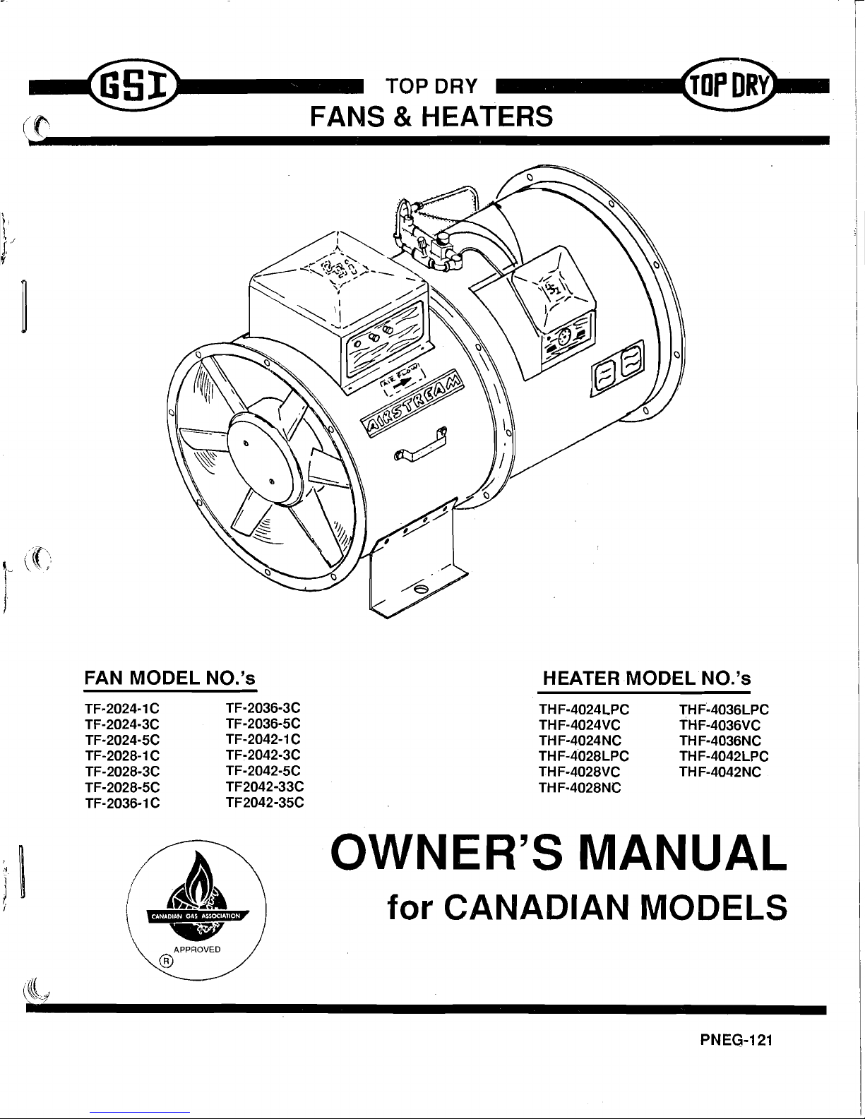
FANS &HEATERS
FAN MODEL NO.'s
TF·2024·1C
TF·2036-3C
TF-2024-3C
TF-2036-5C
TF·2024-5C
TF-2042-1C
TF-2028-1C
TF-2042-3C
TF-2028-3C
TF-2042-5C
TF-2028-5C
TF2042-33C
TF-2036·1C
TF2042-35C
1\(
1,,,4,,,,
~
APPROVED
®
HEATER
MODEL
NO.'s
THF-4024L,PC
THF~4036LPC
THF-4024VC
THF·4036VC
THF·4024NC
THF-4036NC
THF-4028LPC
THF-4042LPC
THF·4028VC
THF-4042NC
THF-4028NC
OWNER'S MANUAL
for CANADIAN MODELS
PNEG-121
Page 2
WARRANTY
·GRAIN
SYSTEMS,
INC.
warrants
all
products
manufactured
by
GRAIN
SYSTE~IS,
INC.
to
be
free
of
defects
in
materials
and
workmanship
under
usual
and
customary
service.
GRAIN
SYSTENS,
INC.
only
obligation
is
to
repair
or
replace
products
returned
on a
prepaid
basis
within
12
months
after
retail
sale,
and,
in
our
opinion,
found
to
be
defective
due
to
material
of
wor~nanship.
If
defective,
the
product
will
be
repaired
of
replaced
without
charge,
F.O.B.
factory,
this
constituting
and
fulfilling
our
warranty
obligation.
Expenses
incurred
without
authorization
of
GRAIN
SYSTEMS,
INC.
shall
be
the
sole
responsibility\
of
the
bearer.
Under no
circumstances
wiil
G~IN
SYSTH1S,
INC. be
liable
for
any
kind
of
special
of
consequential
damages,
nor
will
the
liabilty
ever
exceed
the
selling
price
of 'the
product.
This
warranty
does
not
cover
products
or
parts
which
have
been
damaged
by
negligent
use,
misuse,
alteration
of
accident.
All
products
supplied
by
outside
manufacturers
are
warranted
seperately
by
the
respectiv~
manufacturer.
This
war~anty
is
exclusive
and
in
lieu
of
all
other
warranties,
expressed
of
implied.
GRAIN
SYSTE~IS,
INC.
reserves
the
right
to
make
design
or
specification
changes
at
any
time,
without
an
contingent
obligation
to
purchasers
or
products
already
sold.
All
instructions
shall
be
construed
as
recommendations
only;
because
the
actual
installation
may
vary
according
to
local
conditions
and
GRAIN
SYSTENS,
INC.
assumes
no
liability
for
results
arising
from
the
use
of
such
recommendations.
GRAIN
SYSTEMS,
INC.
assumes
no
responsibility
for
field
modifi-
cations
or
erection
defects
which
create
structural
or
storage
quality
problems.
If
any
field
modifications
are
necessary
which
are
not
specifically
covered
by
the
contents
of
this
manual,
contact
GRAIN
SYSTENS,
INC.
for
recommendations
and
approval.
Any
unauthorized
modification
or
erection
defect
which
effects
th~
structural
integrity
of
the
G.S.I.
bin
will
be
cause
for
immediate
nullification
of
the
G.S.I.
bin
warranty.
ROO'
DAMAGE
WARNIM.G
GRAIN
SYSTENS,
INC.
cannot
warrant.
any
roof
damages due
to
excessive
vacuum
or
internal
pressure
caused
by
fans
or
other
air
moving
systems
Adequate
ventilation
and/or
"make-up
air"
devices
should
be
prov:..lted
for
all
powered
air
handling
systems.
GRAIN
SYSTEMS,
INC.
does
not
recommend
the
use
of
downward
flow
systems
(suction).
Severe
roof
structural
damage
can
result
from
any
blockage
of
air
passages.
Running
of
fans
during
certain
high
humidity/cold
weather
conditions
can
cause
freezing
over
of
air
exhaust
or
intake
ports.
THIS
EQUIPMENT
SHALL
BE
INSTALLED IN
ACCORDANCE
WITH
THE
CURRENT
INSTALLATION
CODES
FOR
GAS
BURNING
APPLIANCES
AND
EQUIP-
MENT,
CAN1-B149.1
AND
B149.2,
OR
APPLICABLE PROVINCIAL REGULATIONS
WHICH
SHOULD
BE
CAREFULLY
FOLLOWED
IN
ALL
CASES. AUTHORITIES
HAVING
JURISDICTION
SHOULD
BE
CONSULTED
BEFORE
INSTALLATIONS
ARE
MADE.
Page 3
CONTE1\fTS
PAGE
FAN
SPECIFICATIONS
1
FAN
INSTALLATION 2
FAN
SERVICE 2
FAN
TROUBLESHOOTING
CHART
4
24"
FAN
PARTS 5
24"
FAN 1 PHASE
WIRING
DIAGRAM
8
28"
FAN
PARTS 9
28"
FAN 1 PHASE
WIRING
DIAGRAM
12
36"
FAN
PARTS
13
42"
10-16
H.P.
FAN
PARTS
14
36"
&
42"
10-16
H.P.
FAN
1 PH. WIRING DIAG
17
42"
30 H. P .
FAN
PARTS
18
220
VOLT 3 PHASE
WIRING
DIAGRAM
20
440
VOLT 3 PHASE
WIRING
DIAGRAM
21
HEATER
SPECIFICATIONS
22
FUNCTION
OF
HEATER
PARTS
23
FUNCTION
OF
VAPORIZER PARTS
24
HEATER
INSTALLATION 24
HEATER
OPERATION
25
HEATER
SERVICE
26
ADJUSTING
PRIMARY
AIR
DAMPER
PLATE
27
HEATER
TROUBLESHOOTING
CHART
28
HEATER
WIRING
DIAGRAMS
29
HI-LO
THERMOSTAT
30
HI-LO
THERMOSTAT
WIRING
DIAGRAM
31
MOUNTING
TEMPLATE
FOR
THERMOSTAT
32
Page 4
--
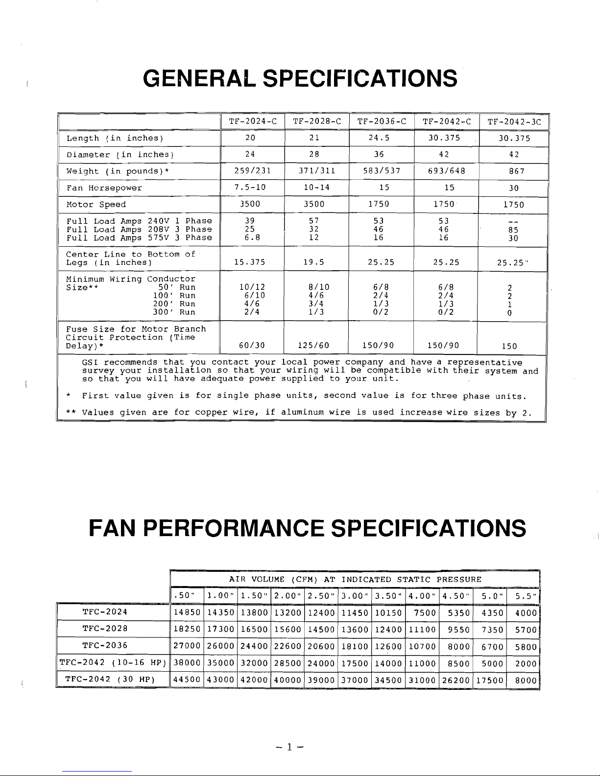
GENERAL SPECIFICATIONS
TF-2024-C
TF-2028-C
TF-2036-C
TF-2042-C
TF-2042-3C
20
21
24.5
30.375
Length
(in
inches)
30.375
24
28
36 42
Diameter
(in
inches)
42
259/231
371/311
583/537
693/648
Weight
(in
pounds)*
867
7.5-10
10-14
15
15
Fan
Horsepower
30
3500
1750
3500
1750
Motor
Speed
1750
39
57
Full
Load
Amps
240V
1
Phase
53 53
Full
Load
Amps
208V
3
Phase
25
I
32
46 46
85
Full
Load
Amps
575V
3
Phase
6.8
12 16 16
30
Center
Line
to
Bottom
of
Legs
(in
inches)
15.375
19.5
25.25
25.25
-.
25.25
Minimum
Wiring
Conductor
Size**
50'
Run
10/12
8/10
6/8 6/8
2
100'
Run
6/10
4/6
2/4
2/4
2
200'
Run
4/6
1/3
3/4
1/3
1
300'
Run
2/4
1/3
0/2
0/2
0
Fuse
Size
for
Motor
Branch
Circuit
Protection
(Time
De1ay)*
60/30
125/60
150/90
150/90
150
GSI
recommends
that
you
contact
your
local
power
company
and
have a representative
survey
your
installation
so
that
your
wiring
will
be
compatible
with
their
system
and
so
that
you
will
have
adequate
power
supplied
to
your
unit.
First
value
given
is
for
single
phase
units,
second
value
is
for
three
phase
units.
*
**
Values
given
are
for
copper
wire,
if
aluminum
wire
is
used
increase
wire
sizes
by
2.
FAN PERFORMANCE SPECIFICATIONS
AIR
VOLUME
(CFM)
AT
INDICATED
STATIC
PRESSURE
.50
"
1.00
"
1.50"
2.00"
2.50"
3.00" 3.50"
4.00"
4.50"
5.0" 5.5"
TFC-2024
14850
14350
13800
13200 12400 11450
10150
7500
5350
4350 4000
TFC-2028
18250
17300
16500 15600
14500
13600
12400 11100
9550
7350
5700
TFC-2036
27000
26000 24400
22600
20600
18100
12600 10700
8000
6700
5800
TFC-2042
(10-16
HP)
38000
35000
32000
28500
24000
17500
14000
11000
8500
5000
2000
TFC-2042
(30
HP)
44500
43000
42000
40000
39000 37000 34500 31000
26200
17500
8000
-1-
Page 5
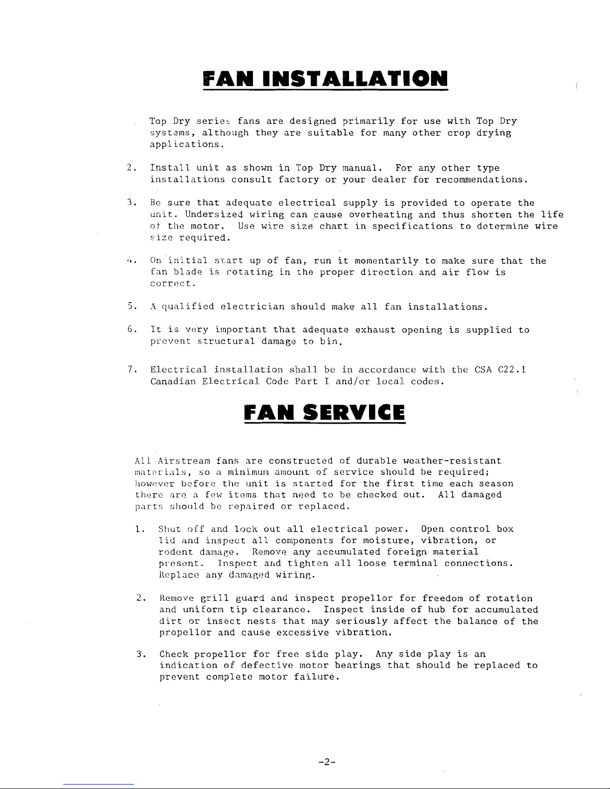
FAN
INSTALLATION
Top
Dry
serie~
fans
are
designed
primarily
for
use
with
Top
Dry
systems,
although
they
are
suitable
for
many
other
crop
drying
applications.
2.
Install
unit
as
shown
in
Top
Dry
manual.
For
any
other
type
installations
consult
factory
or
your
dealer
for
recommendations.
3.
Be
sure
that
adequate
electrical
supply
is
provided
to
operate
the
unit.
Undersized
wiring
can
cause
overheating
and
thus
shorten
the
life
of
tile
motor.
Use
wire
size
chart
in
specifications
to
determine
wire
~ize
required.
4.
On
initial
start
up
of
fan,
run
it
momentarily
to
make
sure
that
the
fan
blade
is
rotating
in
the
proper
direction
and
air
flow
is
correct.
5.
A
qualified
electrician
should
make
all
fan
installations.
6.
It
is
v~ry
important
that
adequate
exhaust
opening
is
supplied
to
prevent
structural
damage
to
bin.
7.
Electrical
installation
shall
be
in
accordance
with
the
CSA
C22.l
Canadian
Electrical
Code
Part
I
and/or
local
codes.
FAN
SERVICE
All
Airstream
fans
are
constructed
of
durable
weather-resistant
I~at~rials,
so a minimum
amount
of
service
should
be
required;
hOWl'vcr
bcfoLe
the
unit
is
started
for
the
first
time
each
season
there
are a few
items
that
need
to
be
checked
out.
All
damaged
parts
should
be
repaired
or
replaced.
1.
Shut
off
and
locl~
out
all
electrical
power.
Open
control
box
lid
and
inspect
all
components
for
moisture,
vibration,
or
rodent
damaGe.
Remove
any
accumulated
foreign
material
present.
Inspect
and
tighten
all
loose
terminal
connections.
Replace
any
damaRed
wiring.
2.
Remove
grill
guard
and
inspect
propellor
for
freedom
of
rotation
and
uniform
tip
clearance.
Inspect
inside
of
hub
for
accumulated
dirt
or
insect
nests
that
may
seriously
affect
the
balance
of
the
propel
lor
and
cause
excessive
vibration.
3.
Check
propel
lor
for
free
side
play.
Any
side
play
is
an
indication
of
defective
motor
bearings
that
should
be
replaced
to
prevent
complete
motor
failure.
-2-
Page 6
4.
Motor
bearings
should
be
greased
periodically
depending
upon
usage.
Under
normal
conditions
it
is
a good
idea
to
have
motor
serviced
at
an
authorized
service
center
every
three
to
four
seasons.
Note:
It
is
important
that
motor
bearings
are
greased
with
high
quality
motor
bearing
grease
available
from
an
authorized
service
center.
5.
Check
magnetic
starter
for
dirt
or
other
corrosion
on
contact
points.
If
points
show
signs
of
wear
they
should
be
replaced.
FUNCTION
OF
FAN
PARTS
PROPELLOR:
Specially
designed
to
move
air
through
grain.
SPLIT
TAPER
BUSHING:
Locks
fan
blade
to
motor
shaft.
ELECTRIC
NOTOR:
Provides
power
and
mounting
for
faJil
blade.
MOTOR
CONTROL:
Pl'ovides
start
and
stop
of
fan.
RED
LIGHT:
Indicates
that
fan
is
running.
OVER
LOADS:
Kicks
out
motor
controls
in
event
of
motor
overload
situation.
VENTURI:
Increases
effeciency
of
fan.
CAPACITORS:
(SINGLE
PHASE)
Provide
correct
electrical
characteristics
for
single
phase
motors
-3-
Page 7
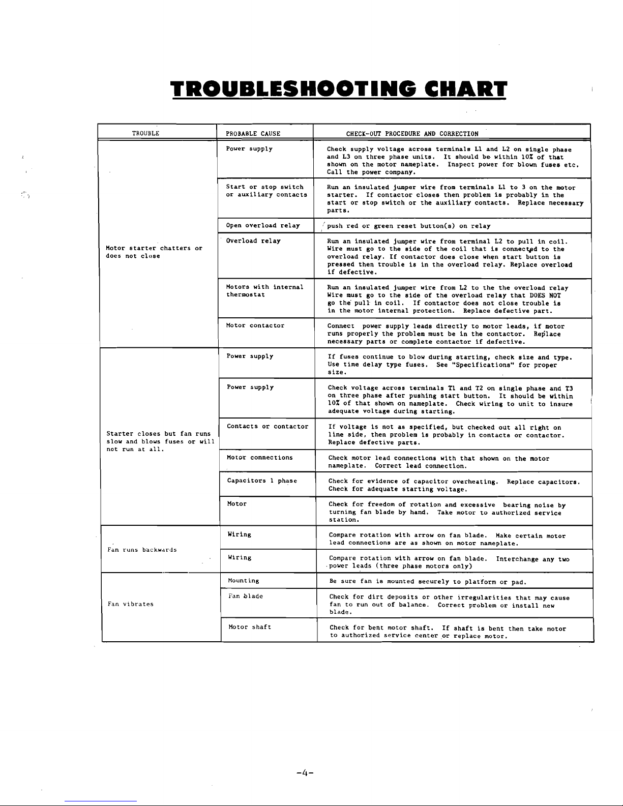
TROUBLESHOOTING
CHART
TROUBLE
PROBABLE
CAUSE
CHEC~-OUT
PROCEDURE
AND
CORRECTION
Power
supply
Check
supply
voltage
across
terminals
Ll
and
L2
on
single
phase
and
L3
on
three
phase
units.
It
should
be
within
lOt
of
that
shown on
the
motor
nameplate.
Inspect
power
for
blown
fuses
etc.
Call
the
power company.
Star.t
or
stop
switch
or
auxiliary
contacts
Run
an
insulated
jumper
wire
from
terminals
Ll
to
3 on
the
motor
starter.
If
contact
or
closes
then
problem
is
probably
in
the
start
or
stop
switch
or
the
auxiliary
contacts.
Replace
necessary
parts.
Hotor
starter
chatters
or
does
not
close
Open
overload
relay
Overload
relay
push
red
or
green
reset
button(s)
on
relay
Run
an
insulated
jumper
wire
from
terminal
L2
to
pull
in
coil.
Wire must go
to
the
side
of
the
coil
that
is
connec~d
to
the
overload
relay.
If
contactor
does
close
wh~n
start
button
is
pressed
then
trouble
is
in
the
overload
relay.
Replace
overload
if
defective.
Motors
with
internal
thermostat
Motor
contactor
Power
supply
Run
an
insulated.
jumper
wire
from
L2
to
the
the
overload
relay
Wire must go
to
the
side
of
the
overload
relay
that
DOES
NOT
go
the·
pull
in
coil.
If
contactor
does
not
close
trouble
is
in
the
motor
internal
protection.
Replace
defective
part.
Connect
power
supply
leads
directly
to
motor
leads,
if
motor
runs
properly
the
problem
must
be
in
the
contactor.
Replace
necessary
parts
or
complete
contactor
if
defective.
If
fuses
continue
to
blow
during
starting,
check
s
he
and
type.
Use
time
delay
type
fuses.
See
"Specifications"
for
proper
size.
Power
supply
Check
voltage
across
terminals
Tl
and
T2
on
single
phase
and
T3
on
three
phase
after
pushing
start
button.
It
should
be
within
(
lOt
of
that
shown
on
nameplate.
Check
wiring
to
unit
to
insure
adequate
voltage
during
starting.
Starter
closes
but
fan
runs
slow
and blows
fuses
or
will
not
run
at
all.
Contacts
or
contactor
Motor
connections
If
voltage
is
not
as
specified,
but
checked
out
all
right
on
line
side,
then
problem
is
probably
in
contacts
or
contactor.
Replace
defective
parts.
Check
motor
lead
connections
with
that
shown
on
the
motor
nameplate.
Correct
lead
connection.
Capacitors
1
phase
Motor
Check
for
evidence
of
capacitor
overheating.
Replace
capacitors.
Check
for
adequate
starting
voltage.
Check
for
freedom
of
rotation
and
excessive
bearing
noise
by
turning
fan
blade
by
hand.
Take
motor
to
authorized
service
station.
Fan
runs
ba.ckwards
Fan
vibrates
Wiring
Wiring
Mounting
Fan
blade
Compare
rotation
with
arrow
on
fan
blade.
Make
certain
motor
lead
connections
are
as
shown
on
motor
nameplate.
Compare
rotation
with
arrow
on
fan
blade.
Interchange
any
two
.
power
leads
(three
phase
motors
only)
Be
sure
fan
is
mounted
securely
to
platform
or
pad.
Check
for
dirt
deposits
or
other
irregularities
that
may
cause
fan
to
run
out
of
balance.
Correct
problem
or
install
new
blade.
Motor
shaft
Check
for
bent
motor
shaft.
If
shaft
is
bent
then
take
motor
to
authorized
service
center
or
replace
motor.
-4-
Page 8
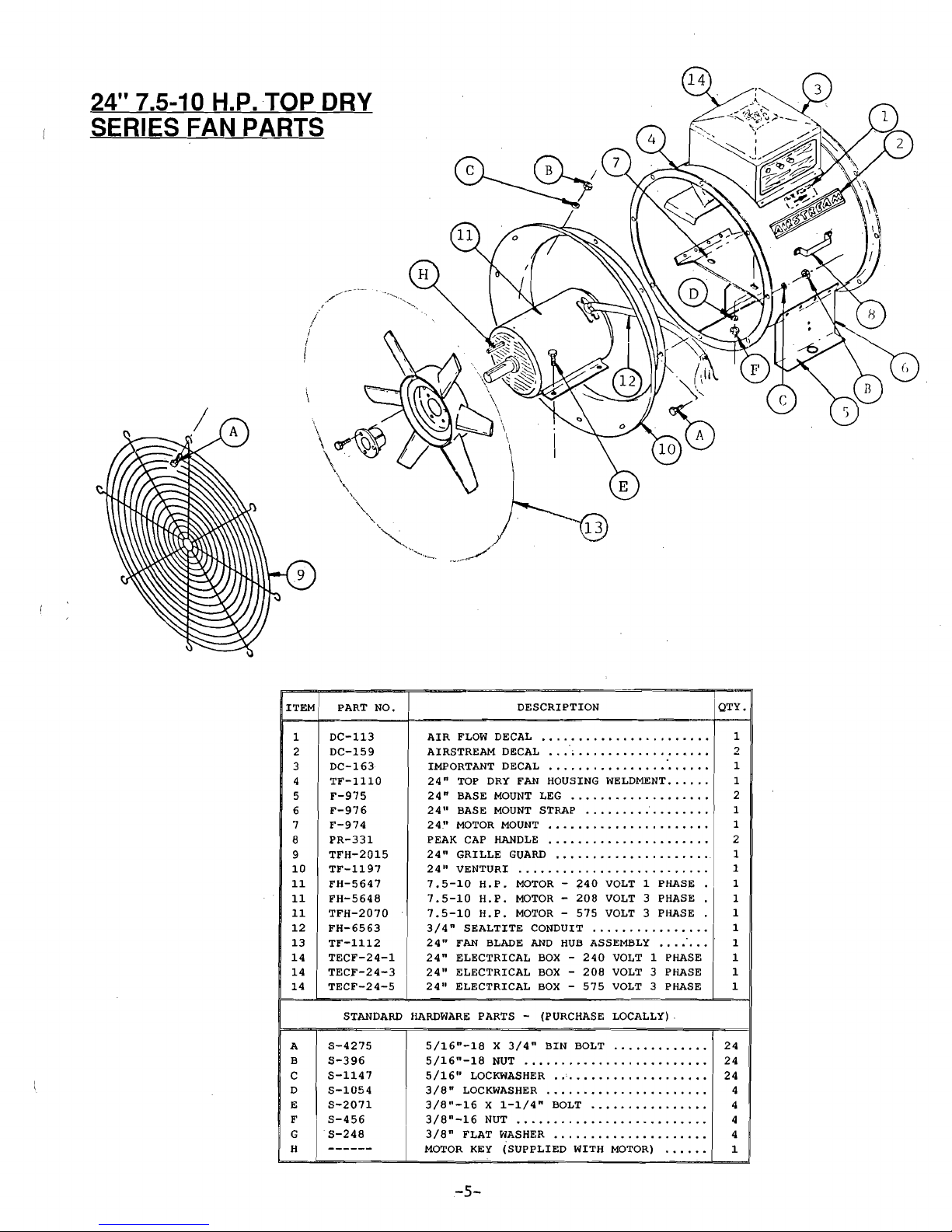
24" 7.5-10 H.P.
TOP
DRY
SERIES FAN PARTS
/
I
I
I
ITEM
PART
NO.
DESCRIPTION QTY.
1
DC-113
AIR
FLOW
DECAL
.
"-
...
"-.
"-
...............
1
2
DC-159
AIRSTREAM
DECAL
...
~
.............."- ..
"-
2
3
DC-163
IMPORTANT
DECAL
.............
"-
..................
"-
I
4
TF-I110
24"
TOP
DRY
FAN
HOUSING
WELDMENT
......
1
5
F-975
24"
BASE
MOUNT
LEG
............
"-
..........
2
6
F-976
24"
BASE
MOUNT
STRAP
............................
1
7
F-974
24"
MOTOR
MOUNT
................................
1
8
PR-331
PEAK
CAP
HANDLE
...............
"-
.....................
2
9
TFH-2015
24"
GRILLE
GUARD
....................................
1
10
TF-1197
24"
VENTURI .....................................
"-
I
11
FH-5647
7.5-10
H.P.
MOTOR -240
VOLT 1 PHASE
1
11
FH-5648
7.5-10
H.P.
MOTOR -208
VOLT 3 PHASE
1
11
TFH-2070
7.5-10
H.P.
MOTOR -575
VOLT 3 PHASE
1
12
FH-6563
3/4"
SEALTITE
CONDUIT
...
"-
...................
1
13
TF-1112
24"
FAN
BLADE
AND
HUB
ASSEMBLY
............ 1
14
TECF-24-1
24"
ELECTRICAL
BOX -240
VOLT 1 PHASE
1
14
TECF-24-3
24"
ELECTRICAL
BOX -208
VOLT 3 PHASE
1
14
TECF-24-5
I
24"
ELECTRICAL
BOX
-
575
VOLT 3 PHASE
1
STANDARD
HARDWARE
PARTS -
(PURCHASE
LOCALLY)
.
A
B
C
D
E
F
G
H
5-4275
5-396
5-1147
S-1054
S-2071
S-456
5-248
5/16"-18 X 3/4"
BIN
BOLT
'"
24
5/16"-18
NUT
..................•......
24
5/16"
LOCKWASHER ..'.
. . . . . . . . . . . . . . • • . .
24
3/8"
LOCKWA5HER
4
3/8"-16 X 1-1/4"
BOLT
4
3/8"-16
NUT
.....•....................
4
3/8"
FLAT
WASHER
4
MOTOR
KEY
(SUPPLIED
WITH
MOTOR)
1
-5-
Page 9

24"
7.5-10
~
1
PHASE
FAN
CONTROL
BOX
PARTS
ITEM PART NO. DESCRIPTION
QTY.
1
DC-381
CANADIAN
FAN
ELECTRICAL
BOX
DECAL
........
1
2
F-747
CAPAC~TOR
RETAINER
CLIP
............................
1
3
DC-437
24"
1 PHASE
WIRING
DIAGRAM
DECAL
..........
1
4
TFC-0028
STOP SWITCH
....................................................
1
5
TFC-0029
START
SWITCH
..................................................
1
6
TFC-0063
HEATER
STRIP
..................................................
1
7
TF-1185
24"
FAN
BOX
WELDMENT
..................................
1
8
TFC-0057
CONTACTOR
........................................................
1
9
TFC-0044
OVERLOAD
RELAY
..............................................
1
10
TFC-0018
TERMINAL
STRIP
.............................................. 1
11
TFH-2052
TERMINAL
STRIP
MARKER
................................ 1
12
---------
START
CAPACITORS
(BALDOR)
........................
AR
13
TFC-0012
RED
LIGHT
........................
.........
-
......................
1
STANDARD
HARDWARE
PARTS -(PURCHASE
LOCALLY)
A
S-6557
#8-32
X
3/4"
SHEET
METAL
SCREW
..............
2
B
S-1040
#8-32
X
1/4"
SHEET
METAL
SCREW
.............. 6
C
S-2605
1/4"-20
X
1-1/4"
SHEET
METAL
SCREW
...
1
-_.
_....
-_
..
-6-
Page 10

6
24"
7.5-10
H.P.
208 & 575
VOLT
3 PHASE
FAN
CONTROL
BOX
PARTS
Ie
QTY.
DESCRIPTION
PART NO.
1
CANADIAN
FAN
ELECTRICAL
BOX
DECAL
........
DC-381
1
208
VOLT
3
PHASE
WIRING
DIAGRAM
DECAL. 1
2
DC-379
575
VOLT
3
PHASE
WIRING
DIAGRAM
DECAL. 1
2
DC-380
1
STOP SWITCH
....................................................
TFC-0028
3
1
START SWITCH
..................................................
4
TFC-0029
HEATER
STRIP
(208
VOLT
ONLY)
..................
TFC-0041
5
~
HEATER
STRIP
(575
VOLT
ONLY)
.................. 3
TFC-0065
5
24"
FAN
CONTROL
BOX
WELDMENT
..................
1
TF-1185
6
CONTACTOR
........................................................ 1
7
TFC-0059
TERMINAL
STRIP
.............................................. 1
TFC-0018
8
TERMINAL
STRIP
MARKER
................................ 1
TFH-2052
9
RED
LIGHT
........................................................ 1
10
TFC-0012
TFC-0039
TRANSFORMER
575-120
V
(575
VOLT
ONLY)
.
1
11
TFC-0042
AUXILIARY POINTS
(575
VOLT
ONLY)
.......... 1
12
TFC-0043
COIL
-
120
VOLTS
(575
VOLT
ONLY)
.......... 1
13
STANDARD
HARDWARE
PARTS -(PURCHASE LOCALLY)
A
S-6557
#8-32
X
3/4"
SHEET
METAL
SCREW
..
... ........ " 4
B
S-1040
#8-32
X
1/4"
SHEET
METAL
SCREW
..............
4
-7-
Page 11
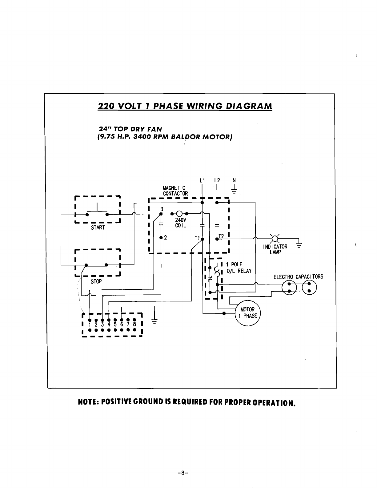
220
VOLT
1 PHASE
WIRING
DIAGRAM
24"
TOP
DRY
FAN
(9.75
H.P.
3400
RPM
BALpOR
MOTOR)
L1
L2
N
MAGNETIC
JL
CONTACTOR
/ ,
INDICATOR
LAMP
_I
1 1
POLE
lOlL
RELAY
1
START
- :
f.-.'
1
I
123
4 5 6 7 8 I
~
1
••••••••
1
--------
,.----
...
1
1
... .J
!
STOP
NOTE:
POSITIVE
GROUND
IS
REQUIRED
FOR
PROPER
OPERATION.
-8-
Page 12
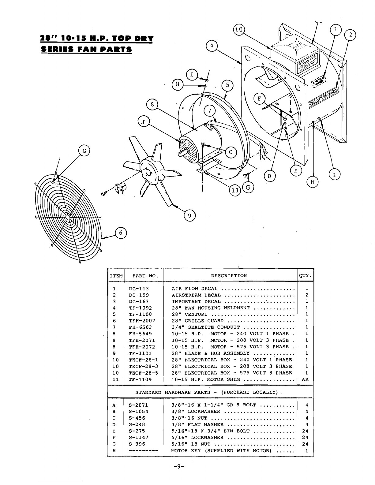
28"
10-15
R.P.
TOP
DRY
SIRIIS
'AN
PARTS
G
DESCRIPTION QTY.
1
DC-113
ITEM
PART
NO.
AIR
FLOW
DECAL
. 00000000.. ... •.•. .•.. . 1
AIRSTREAM
DECAL
2
2
DC-159
3
DC-163
IMPORTANT
DECAL
..
1
28"
E'AN
HOUSING
WELDMENT
1
4
TF-1092
5
TF-1108
28"
VENTURI 10 • • • • • • • • • • • • • • • •
28"
GRILLE
GUARD
.0...................
1
6
TFH-2007
3/4"
SEALTITE
CONDUIT
1
7
FH-6563
10-15
H.P.
MOTOR -240
VOLT 1 PHASE
1
8
FH-5649
10-15
H.P.
MOTOR -208
VOLT 3 PHASE
1
8
TFH-2071
8
TFH-2072
10-15
HoP.
MOTOR -575
VOLT 3 PHASE
1
28"
BLADE & HUB
ASSEMBLy.............
1
9
TF-1101
28"
ELECTRICAL
BOX -240
VOLT 1 PHASE
1
10
TECF-28-1
28"
ELECTRICAL
BOX -208
VOLT 3 PHASE
1
10
TECF-28-3
28"
ELECTRICAL
BOX -575
VOLT 3 PHASE
1
10
'J'ECF-28-5
10-15
H.P.
MOTOR
SHIM................
AR
STANDARD
HARDWARE
PARTS -(·PURCHASE
LOCALLY)
A
11
TF-1109
3/8"-16
X
1-1/4"
GR 5 BOLT
4
S-2071
3/8"
LOCKWASHER
4
B
S-1054
C
S-456
3/8"-16
NUT
0.................
4
S-248
3/8"
FLAT
WASHER
0
.....•.•.•
00•. 4
D
S-275
5/16"-18
X
3/4"
BIN
BOLT
24
E
F
S-1147
5/16"
LOCKWASHER
00
0............
24
G
5/16"-18
NUl'
....
0
........•...
0.0.....
24
S-396
H
MOTOR
KEY
(SUPPLIED
WITH
MOTOR)
1
-9-
Page 13

~
10 15
~
~
PHASE
FAN
CONTROL
BOX
PARTS
-
. .
ITEM
PART
NO.
1
DC-381
2
DC:-436
3
TFC-0028
4
TFC-0029
5
TFC-0045
6
TF-1187
7
TF-1096
8
TFC-0044
9
TFC-0001
10
TFC-0018
11
TFH-2052
12
---------
13
TFC-0012
14
---------
STANDARD
A
S-6557
B
S-1040
C
S-1102
D
S-4627
DESCRIPTION
CANADIAN
FAN
ELECTRICAL
BOX
DECAL
........
28" 1 ,PHASE
WIRING
DIAGRAM
DECAL
..........
'---
/'
.
STOP SWITCH .................. ...
..............................
"
START SWITCH
..................................................
HEATER
STRIP
..................................................
28"
FAN
CONTROL
BOX
WELDMENT
..................
CAPACITOR
HALF
CLAMP
(BALDOR)
................
OVERLOAD
RELAY
..............................................
CONTACTOR
........................................................
TERMINAL
STRIP
..............................................
TERMINAL
STRIP
MARKER
................................
BALDOR
RUN
CAPACITORS
(OIL)
....................
RED
LIGHT
D
......................................................
BALDOR
START CAPACITORS (ELECTRO)
........
HARDWARE
PARTS
-
(PURCHASE
LOCALLY)
#8-32
X
5/8"
SHEET
METAL
SCREW
..............
#8-32
X
1/4"
SHEET
METAL
SCREW
..............
1/4"-20
NUT
....................................................
1/4"-20
X
2-1/2"
MACHINE
SCREW
..............
-10-
-
QTY.
1
1
1
1
1
1
2
1
1
1
1
AR
1
AR
2
8
2
2
Page 14

28"
10-15
H.P.
208 & 575
VOLT 3 PHASE
FAN
CONTROL
BOX
PARTS
r
QTY.
ITEM
PART
NO.
DESCRIPTION
1
1
CANADIAN
FAN
ELECTRICAL
BOX
DECAL
........
DC-381
1
208
VOLT
3
PHASE WIRING
DIAGRAM
DECAL
2
DC-379
1
575
VOLT 3 PHASE
WIRING
DIAGRAM
DECAL
2
DC-380
1
STOP SWITCH
.......................................... "
....
"
..
3
TFC-0028
1
TFC-0029
4
START
SWITCH
..................
""
............
""
............
TFC-0061
HEATER
STRIP
(208
VOLT
ONLY)
.................. 3
5
HEATER
STRIP
(575
VOLT
ONLY)
..................
TFC-0064
3
5
1
TF-1187
28"
FAN
CONTROL
BOX
WELDMENT
.............. "
..
6
1
CONTACTOR
(208
VOLT
ONLY)
........................
7
TFC-0050
1
CONTACTOR
(575
VOLT
ONLY)
........................
7
TFC-0059
1
8
TFC-0018
TERMINAL
STRIP
..............................................
TFH-2052
9
TERMINAL
STRIP
MARKER
................................ 1
TFC-0012
1
10
RED
LIGHT ........................................................
TFC-0039
TRANSFORMER
575-120V
(575
VOLT
ONLY)
11
1
I
12
TFC-0042
AUXILIARY POINTS
(575
VOLT
ONLY)
..........
1
I
13
TFC-0043
J
COIL -120
VOLTS
(575
VOLT
ONLY)
.......... 1
I
STANDARD
HARDWARE
PARTS -(PURCHASE
LOCALLY)
S-6557
#8-32 X 3/4"
SHEET
METAL
SCREW
.......
~I
~
S-10<10
!
#8-32
X
1/4"
SHEET
METAL
SCREW
.......
i 6
.-
-_.-
J
-
---
-
-.-
-~-
-11-
I
Page 15

-12-
220
VOLT 1 PHASE
WIRING
DIAGRAM
28"
TOP
DRY
FAN
PO-15
H.P.
3400
RPM
SALDOR
MOTOR}
OIL
CAPACITORS
1
POLE
lOlL
RELAY
1
L1
L2
N
MAGNETIC
~
CONTACTOR
1-
- f
-,
l
-
--
1123456781
L
-_-
.=. ~-
.:
:.
-_I
_____
1
START
1-----
1 1
NOTE:
POSITIVE
GROUND
IS
REQUIRED
FOR
PROPER
OPERATION.
Page 16

36"
10-16
H.P.
TOP
DRY
SIRIIS
'AN
PARTS
/
/
®-Jr'
o
.~
/
9
lTEM
PART
NO.
1
2
3
4
5
6
7
8
8
8
9
10
10
10
11
12
DC-113
DC-159
DC-163
TF-1017
TF-1050
TFH-2002
FH-6564
TFH-2054
TFH-2068
TFH-2066
TF-1053
TECF-36-1
TECF-36-3
TECF-36-5
TF-1116
TF-1037
DESCRIPTION QTY.
AIR
FLOW
DECAL .'.
. . . . . . . . . . . . . . • . . . . . • 1
AIRSTREAM
DECAL
2
iMPORTANT
DECAL
..............•.......
1
36"
FAN
HOUSING
WELDMENT
1
36"
VENTURI 1
36"
GRILLE
GUARD
1
1"
SEALTITE
CONDUIT
.....•............
'1
10-16
H.P.
MOTOR -240
VOLT 1 PHASE
1
10-16
H.P.
MOTOR -208
VOLT 3 PHASE
1
10-16
H.P.
MOTOR -575
VOLT 3 PHASE
1
36"
FAN
BLADE & HUB
ASSEMBLy.........
1
36"
ELECTRICAL
BOX -240
VOLT 1 PHASE
1
36"
ELECTRICAL
BOX -208
VOLT 3 PHASE
1
36"
ELECTRICAL
BOX -575
VOLT
3 PHASE 1
3
PHASE
ADAPTOR
(3
PHASE
ONLY)
...•...
1
10-16
H.P.
MOTOR
SHIM
AR
STANDARD
HARDWARE
PARTS -
(PURCHASE
LOCALLY)
A
B
C
D
E
F
G
H
S-4275
S-1147
S-396
S-1054
S-456
S-2071
S-248
5/16"-18
X
3/4"
BIN
BOLT
24
5/16"
LOCKWASHER
.................•...
24
5/16"-18
NUT.........................
24
3/8"
LOCKWASHER
...........•..••......
4
3/8"-16
NUT
4
3/8"-16
X
1-1/4"
BOLT
4
3/8"
FLAT
WASHER.....................
4
MOTOR
KEY
(SUPPLIED
WITH
MOTOR)
..
....
1
-13-
Page 17

42"
10-16
R.P.
TOP
DRY
SIRIIS
'AN
PARTS
/
CD
-J
CiJ1
/
/
A
DESCRIPTION QTY.
ITEM PART NO.
1
2
3
4
5
6
7
8
8
8
9
10
11
11
11
12
13
DC-113
DC-159
DC-163
TF-1121
TF-I082
TFH-2003
FH-6564
TFH-2054
TFH-2068
TFH-2066
TF-I086
FH-1108
TECF-42-1
TECF-42-3
TECF-42-5
'XF-1116
TF-I037
AIR
FLOW
DECAL
.
AIRSTREAM
DECAL
.
IMPORTANT
DECAL
....................•.
42"
10-16
H.P.
FAN
HOUSING
WELDMENT
..
42"
VENTURI .
42"
GRILLE
GUARD
.
1"
SEALTITE CONDUIT .
10-16
H.P.
MOTOR -240
VOLT
1 PHASE
..
10-16
H.P.
MOTOR -208
VOLT
3 PHASE
..
10-16
H.P.
MOTOR -575
VOLT
3 PHASE
..
42"
FAN
BLADE & HUB
ASSEMBLy .
BLADE
HUB
CAP
.
42"
ELECTRICAL
BOX -240
VOLT
1 PHASE
42"
ELECTRICAL
BOX
- ·208
VOLT
3 PHASE
42"
ELECTRICAL
BOX -575
VOLT
3 PHASE
3 PHASE ADAPTER
(3
PHASE
ONLY)
.
10-16
H.P.
MOTOR
SHIM .
I
1
2
1
1
1
1
1
1
1
1
1
1
1
1
1
1
AR
STANDARD
HARDWARE
PARTS - (PURCHASE
LOCALLY)
A
S-4275
5/16"-18
X
3/4"
BIN
BOLT
24
B
S-l147
5/16"
LOCKWASHER
24
C
S-396
5/16"-18
NUT
24
D
S-1054
3/8"
LOCKWASHER
4
E
S-456
3/8"-16
NUT..........................
4
F
S-2071
3/8"-16
X
1-1/4"
BOLT
4
G
S-248
3/8"
FLAT
WASHER.............
.. ..
4
H
MOTOR
KEY
(SUPPLIED
WITH
MOTOR)
1
I
HH-1830
1/4"-20
X
1-1/2"
FLAT
HD
MACH.
SCREW
2
-14-
Page 18

---------
---------
---------
~ £ ~
10-16
~
~
PHASE
EAN
C0NTROL
aQX
PARTS
PART
NO. QTY.
ITEM DESCRIPTION
DC-325
1
1
TOP
DRY
FAN
ELECTRICAL
BOX
DECAL
..........
MOTOR
START
RELAY
........................................ 1
2
1
DC-435
36"/42"
1 PHASE WIRING
DIAGRAM
DECAL
3
1
TFC-0028
4 STOP SWITCH
....................................................
5
TFC-0029
START SWITCH .................................................. 1
6
TFC-0047
HEATER
STRIP
................................................. 1
7
TF-1189
36"
FAN
CONTROL
BOX
WELDMENT
.................. 1
7 1
TF-1191
42"
FAN
CONTROL
BOX
WELDMENT
..................
8
TF-I096
2CAPACITOR
HALF
CLAMP
(BALDOR)
................
1
9
TFC-0044
OVERLOAD
RELAY
..............................................
10
TFC-0018
1
TERMINAL
STRIP
..............................................
11
TFH-2052
1
TERMINAL
STRIP
MARKER
................................
12
AR
BALDOR
RUN
CAPACITORS
(OIL)
....................
13
TFC-0002
1
CONTACTOR
........................................................
14
TFC-0012
1
RED
LIGHT ........................................................
15
AR
BALDOR
START CAPACITORS
(ELECTRO)
........
STANDARD
HARDWARE
PARTS -(PURCHASE
LOCALLY)
S";6557
A
*8-32
X
3/4"
SHEET
METAL
SCREW
.............. 2
B
S-4805
*8-32
X
1-1/4"
MACHINE
SCREW
.................. 2
C
8-4627
1/4"-20
X
2-1/2!'
MACHINE
SCREW
.............. 2
D
S-1040
*8-32
X
1/4"
SHEET
METAL
SCREW
..... , .......
8
E
S-1102
2
1/4"-20
NUT
....................................................
-15-
Page 19

~ & ~
~~
~
J
PHASE
EAN
CONTROL
BOX
PARTS
-
. .
IE
,,·~RT
NO.
DC-325
1
2
DC-379
2
DC-380
TFC-0028
3
4
TFC-0029
TFC-0058
5
5
TFC-0046
TF-1189
6
TF-1191
6
7
TFC-0060
7
TFC-0059
8
TFC-0018
TFH-2052
9
TFC-0012
10
11
TFC-0039
TFC-0042
12
13
TFC-0043
STANDARD
A
S-6557
B
S-1040
DESCRIPTION
TOP
DRY
FAN
ELECTRICAL
BOX
DECAL
..........
208
VOLT
3
PHASE
WIRING
DIAGRAM
DECAL
575
VOLT
3
PHASE
WIRING
DIAGRAM
DECAL
STOP
S~ITCH
....................................................
START SWITCH
..................................................
HEATER
STRIP
(208
VOLT
ONLY)
..................
HEATER
STRIP
(575
VOLT
ONLY)
..................
36"
FAN
CONTROL
BOX
WELDMENT
..
" ..............
42"
FAN
CONTROL
BOX
WELDMENT
..................
CONTACTOR
(208
VOLT
ONLY)
........................
CONTACTOR
(575
VOLT
ONLY)
........................
TERMINAL
STRIP
..............................................
TERMINAL
STRIP
MARKER
................................
RED
LIGHT
........................................................
TRANSFORMER
575-120V
(575
VOLT
ONLY)
AUXILIARY POINTS
(575
VOLT
ONLY)
..........
COIL
-
120
VOLTS
(575
VOLT
ONLY)
..........
HARDWARE
PARTS - (PURCHASE
LOCALLY)
#8-32
X
3/4"
SHEET
METAL
SCREW
..............
#8-32 X 1/4"
SHEET
METAL
SCREW
..............
-16-
QTY. J
1
1
1
1
1
3
3
1
1
1
1
1
1
1
1
1
1
2
6
Page 20

__
220
VOLT 1 PHASE
WIRING
DIAGRAM
36" & 42"
TOP DRY
FANS
(70-76
H.P.
7725
RPM
BALDOR
MOTOR)
L1
L2
N
..L
MAGNETIC
,.
-f-,
l
•••
1123456781
1
••••••••
1
--------
...
----.,
1
'----
START
.-----,
I
'----_-1
STOP
CONTACTOR
---
--
OIL
CAPACITORS
~T~T.iEJJY
,.JJ'-----..
______
1
I
1
1
.J
NOTE:
POSITIVE
GROUND
IS
REQUIRED
FOR
PROPER
OPERATION.
-17-
Page 21

42"
30
R.P.
TOP
DRY
SIRIIS
FAN
PARTS
':>
5
l~
DESCRIPTION QTY.
1
DC-113
ITEM
PART
NO.
AIR
FLOW
DECAL
1
AIRSTREAM
DECAL
2
2
DC-159
3
DC-163
IMPORTANT
DECAL
1
42"
30
H.P.
FAN
HOUSING
WELDMENT
1
4
TF-1000
5
TF-1082
42 ~ VENTURI 1
6
TFH-2003
42
~
GRILLE
GUARD
1
42"
FAN
ELECTRIC
BOX
1
7
TF-1011
ELECTRIC
BOX
COVER
1
8
TF-1012
9
FH-6564
1"
SEALTITE
CONDUIT
1
30
H.P.
MOTOR -208
VOLT 3 PHASE.
1
10
TFH-2073
10
TFH-2074
30
H.P.
MOTOR -575
VOLT 3 PHASE
1
42"
30
H.P.
FAN
BLADE & HUB
ASSEMBLY
1
11
TF-1087
12
TF-1036
30
H.
P.
MOTOR
SHIM...................
AR
30
H.P.
ELECTRICAL
BOX -208
VOLT
....
1
13
TECF-42-33
13
TECF-42-35
30
H.P.
ELECTRICAL
BOX -575
VOLT....
1
STANDARD
HARDWARE
PARTS -(PURCHASE
LOCALLY)
A
5/16"-18
X
3/4"
BIN
BOLT
24
S-4275
S-1147
5/16"
LOCKWASHER
24
B
S-396
5/16"-18
NUT
24
C
D
S-1054
3/8"
LOCKWASHER
4
E
S-456
3/8"-16
NUT
4
po
S-2071
3/8"-16
X
1-1/4"
BOLT
4
S-248
3/8"
FLAT
WASHER.....................
4
G
H
MOTOR
KEY
(SUPPLIED
WITH
MOTOR)
1
-18-
Page 22

~
1Q H P
.
.
ITEM
1
2
3
3
4
5
6
6
7
7
8
9
10
11
12
13
14
I A
B
PART
NO.
DC-325
TF-1191
DC-379
DC-380
TFC-0028
TFC-0029
TFC-0066
TFC-0063
TFC-0052
TFC-0050
TFC-0018
TFH-2052
TFC-0012
TFC-0056
TFC-0039
TFC-0043
TFC-0042
STANDARD
HARDWARE
PARTS
-
(PURCHASE
LOCALLY)
#8-32 X 3/4"
SHEET
METAL
SCREW
.............. 2
S-6557
p
#8-32
X
1/4"
SHEET
METAL
SCREW
S-1040
.... e ........
1
PHASE
FAN
CONTROL
BOX
PARTS
DESCRIPTION
QTY
TOP
DRY
FAN
ELECTRICAL
BOX
DECAL
.......... 1
42"
30
H.P.
FAN
CONTROL
BOX
WELDMENT
1
208
VOLT 3 PHASE
WIRING
DIAGRAM
DECAL
1
575
VOLT 3 PHASE
WIRING
DIAGRAM
DECAL
1
STOP
SWITCH
.................................................... 1
START
SWITCH
.................................................. 1
HEATER
STRIP
(208
VOLT
ONLY)
.................. 3
HEATER
STRIP
(575
VOLT
ONLY)
..................
3
CONTACTOR
(208
VOLT
ONLY)
........................ 1
CONTACTOR
(575
VOLT
ONLY)
........................ 1
TERMINAL
STRIP
..............................................
1
TERMINAL
STRIP
MARKER
................................ 1
1
RED
LIGHT ........................................................
1
OVERLOAD
RELAY
(208
VOLT
ONLY)
..............
1
575-120V
TRANSFORMER
(575
VOLT
ONLY)
120V
COIL
(575
VOLT
ONLY)
........................ 1
1
AUXILIARY POINTS
(575
VOLT
ONLY)
..........
-19-
Page 23

208 VOLT 3 PHASE WIRING DIAGRAM
24",
28",
36" & 42"
TOP
DRY
FANS
(BALDOR
MOTORS)
L1
L2
L3
N
r-----.
MAGNETIC
_L
CONTACTOR
--L
L
.J
START
r-----.
J/
/2,
LAMP
INDICATOR
!. -
STOP
- - .Jir=
1_
I I:
~i''-I:>--O_/L_REL]
1E
=E-
1~ -------
r
.-----,
•
••
I
'------{
112345678
....
\
'------1
I
••••••••
I
.--------------\
L.. ....
NOTE:
POSITIVE
GROUND
IS
REQUIRED
FOR
PROPER
OPERATION.
-20-
Page 24

--
575 VOLT 3 PHASE WIRING DIAGRAM
24",
28",
36" & 42"
TOP
DRY
FANS
(BALDOR
MOTORS}
575
TO
120
VOLT
TRAI~SFORMER
.------------,
...-------,
H1
-----I---------tI~
r------a---____+_____
1
I
III----
-
L
L
._..__
._
..
~_.~
r--------
I
:
~
I
'---~
I
~
~
sTiiRT
- - J-
I
r--------
I
I
I
INDICATOR
-1-
~I~
" /
LAMP
I
••
•.
I
112345678
I
I
••••••••
I
'-----
1
H2
H3
H~
_I
. I
------I
1---------'
'-----------,
L3
MAGI~ET
IC
L2
COI~TACTOR
L--_.;
-t-=-;--------J-
- - -
--
- T
-1
I I
I I
I I
L
_J
,
NOTE:
POSITIVE
GROUND
IS
REQUIRED'FOR
PROPER
OPERATION.
-21-
Page 25

SPICIPICATIONS
DL\JILTER
24"
28"
36"
42"
bTU
RATING
2000000
3000000
4000000 5000000
\HEGlIT
110
145
228 286
~lAX
FUEL
FLOI..J
tGPH) 21
32
43
59
LIQUID
OlUfICE SIZE
.177"
.25"
.25"
.438"
mN
OPERATING
PRESSURE
1
3
5
1
~10DELS
HAX
OPERATING
PRESSURE
30 18
30
6
mN
LINE
SIZE
3/8"
3/8"
1/2"
1/2"
MAX
FUEL
FLOW
(CU
FT/HR)
800 118S 1590
----
VAPOR
ORIFICE SIZE
.177"
•25'
.25"
----
~IIN
OPERATING
PRESSURE
1
3
5
----
HODELS
HAX
OPERATING
PRESSURE
30
18
30
----
mN
LINE
SIZE
3/4"
1"
1"
----
HAX
FUEL
FLOIl
(CU
FT/HR)
2100 3000
4200
5000
NAT
GAS
ORIfICE SIZE
.25"
.375
• 375'
.500
mN
OPERATING
PRESSURE
1 1
3
1
~10DELS
HAX
OPERATING
mN
LINE
SIZE
PRESSURE
10
1"
6
10
5
1-1/4" 1-1/2"
2"
HIATER
CONTROL
SPECIFICATIONS
SPARK
PLUG
fUSES
tlI-LHJIT
HOUSING
lII-LHlIT
VAPOR
SOLID
STATE
IGNITION
BOARD
Double
electrode
1/8"
gap
5
amp
250
volt
Opens
circuit
at
200
degrees
f
Opens
circuit
at
180
degrees
f
110 v works
on
flame
rectification
principle
to
prove
flame.
supplys
15000 v
to
spark
plUB
for
iBnition.
-22-
Page 26

FUNCTION OF
HIATIR
PARTS
HEATER
HIGH
LHIIT -
Shuts
down
heater
in
event
housing
temperature
exceeds
200
degrees.
(This
might
occur
if
fan
motor
were
to
fail.)
PRESSURE
GAUGE -Allows
the
manifold
pressure
to
be
monitored
for
regulator
adjustment.
HI-FLANE
SOLENOID
VALVE
--When
closed
forces
gas
to
go
to
bypass
and
tJlrough
adjustable
flow
control
for
low
flame.
When
opened
it
allows
gas
to
flow
straight
through
to
orifice.
LU-FLM1E
SOLENOID
VALVE -Closes
in
event
that
the
low
flame
would
get
to
hot.
SPARK
PLUG -Provides
electric
spark
for
ignition.
BUENEE
SIHTClI -Switches
on
power
to
heater
unit.
l'UWJE
HELAY -Provides
a
ten
second
delay
to
allow
all
gas
to
be
pur~ed
from
heater
and
fan
to
come up
speed
before
first
igniting
burner.
ELECTRONIC
IGNITION
BOARD -Provides
high
voltage
to
spark
plug
for
ignition
and
also
provides
flame
proving
through
flame
rectification.
l'LM1E
SENSOR -Senses
flame
and
sends
:signal
back
ito
ignition
board.
EESEl' -
Locks
out
system
after
repeated
trials
for
ignition.
RED
LIGIIT -Indicates
that
electronic
ignition
board
is
recieving
power.
FUNCTION OF
YAPORIZIR
PARTS
STRAINER -Filters
out
any
foreign
matter
from
gas
line
that
could
lodge
in
gas
solenoid
valve.
SHUT-OFF
VALVE -Starts
or
Stops
flow
of
liquid
to
vaporizer.
SAFETY
RELIEF
VALVE -Releases
pressure
should
blockage
or
pressure
build
up
occur.
SOLENOID
VALVE -Shuts
off
flow
of
liquid
should
vapor
get
overheated
in
cooling
coil.
VAPOR
HIGH
LIHIT -
Senses
overheating
in
cooling
coil
and
sends
signal
to
solenoid
valve
to
close,
shutting
off
flow
of
liquid
to
heater.
COOLING
COIL -Allows
hot
vapor
to
cool
slightly
before
combustion.
VAPORIZER
SUPPORT
WELDMENT -Provides
lateral
and
vertical
movement
of
vaporizer
coil.
-23-
Page 27

HEATER
INSTALLATION
1.
Top Dry
series
heaters
are
designed
primarily
for
use
with
Top
Dry
systems,
although
they
are
suitable
for
many
other
crop
drying
applications.
Instructions
given
in
this
manual
will
assume
that
heater
is
being
installed
on
a Top
Dry.
L.
Bolt
heater
to
downwind
side
of
fan.
(If
required)
Use
3/8"
x
1-1/4"
bolts,
nuts
and
lockwashers.
(not
included)
3.
Hoist
fan
and
heater
unit
up
onto
fan
and
heater
platform.
4.
If
fan
and
heater
unit
is
36"
or
42"
then
the
unit
should
bolt
directly
to
transition
sheeL,
For a 24"
or
28"
fan
and
heater,
unit
must
be
shimmed
under
the
legs
in
order
to
gain
height
required
to
bolt
to
transition.
5.
Wire
fan
as
per
fan
manual
and
CSA
C22.l
Canadian
Electrical
Code
Part I and/or
local
codes.
6.
Wire
heater
to
fan
as
shown
on
the
wiring
diagram.
This
should
be
all
that
is
required
for
wiring
on
heater.
(see
dual
heater
control
instructions
for
wiring
more
than 1 fan
and
heater.)
FUEL
CONNECTION
HIPonTANT -
DO
NOT
USE
pnOPANE
TANKS
WHICH
HAVE
PREVIOUSLY
BEEN
USED
FOn
MU·IONIA
UNLESS
THEY
HAVE
BEEN
PURGED
ACCORDING
TO
PROCEDURES
OF
THE
NATIONAL
L.P. ASSOCIATION.
INVESTIGATE
TO
BE
SUnE
THAT
FUEL
SUPPLY
SYSTEM
COMPLYS
WITH
ALL
LOCAL
CODES
FOR
1.
P.
GAS
INSTALLATIONS.
LIQUID
pnOPANE
MODELS
1.
LP
models
are
designed
to
run
on
liquid
propane,
with
liquid
dra\.]
from
the
propane
tank.
Avoif--using
propane
supply
tanks
that
have
been
used
for
vapor
draw
for
long
periods
of
time.
~~hen
using
liquid
draw
systems
any
moisture
that
may
be
present
in
tank
or
lines
r.lay
freeze
when
system
used
in
cold
weather.
To
avoid
this
the
usual
precaution
is
to
purge
the
system
with
methanol.
2.
nun
proper
size
line
(see
specifications)
to
liquid
pipe
train
on
heater.
Have
qualified
gas
service
man
inspect
installation
to
be
sure
that
every
thing
is
installed
according
to
local
codes
and
ordinances.
3.
After
installation
is
complete
check
all
connections
for
leaks.
-24-
Page 28

,
•
,
PROPANE
VAPOR
NODELS
1.
Propane
vapor
models
are
designed
to
rurr
either
directly
off
of
supply
tank
of
from a separate
external
vaporizer.
2.
!I.
lli~h
pressure
(0-30
lbs.)
regulator
should
be
installed
in
line
to
regulate
gas
flow
to
heater.
24"
model
heaters
have
regulator
installed
on
heater
at
factory.
3.
Run
proper
size
line
(see
specifications)
to
pipe
train
on
heater.
Have a
qualified
gas
service
man
inspect
installation
to
be
sure
that
everything
is
installed
according
to
local
codes
and
ordinances.
4.
!I.Lter
installation
is
complete
check
all
connections
for
leaks.
Ni\TUl:!I.L
G!l.S
r'lOlJU,S
1.
Natural
gas
models
are
similar
to
vapor
models.
but
have a larger
orifice
to
accomodate
lower
pressures
sometimes
found
with
Natural
gas.
2.
?ressure
regulator
must
be
installed
ahead
of
heater
to
adjust
gas
flow.
This
regulator
must
be
capable
of
supplying
the
required
pressure
and
maximum
gas
flow.
(seespecificati6ns)
3.
Run
proper
size
lines
(see
specifications)
to
pipe
train
on
heater.
Have
qualified
gas
service
man
inspect
installation
to
be
sure
that
everything
is
installed
according
to
local
codes
and
ordinances.
4.
After
installation
is
complete
check
all
co~nections
for
leaks.
HEATER
OPERATION
All
Top Dry
heaters
have
standard
a HI-LO
type
pipe
train.
This
style
of
burner
should
burn
constantly
cycling
in
and
out
the
high
flame.
Follow
these
instructions
when
first
starting
up
your
unit
•
1.
The
thermostat
plugs
must
be
plugged
into
heater
control
box
for
heater
to
operate.
(see
thermostat
instructions)
2.
Ope~
all
manual
shut-off
valves
to
heater
unit.
3.
Start
fan.
This
should
supply
power
to
heater
on/off
switch.
4.
Depress
heater
on/off
switch.
Switch
should
stay
in.
To
release_
push
up
on
red
tab
below
the
button.
5.
After
10
seconds
red
indicator
light
should
light
up.
indicating
that
there
is
power
to
the
ignition
board.
-25-
Page 29

6.
Heater
should
now
be
lit.
If
not
check
to
see
that
all
gas
is
on
and
both
thermostats
are
plugged
in.
7.
Turn
thermostat
dial
to
its
highest
setting
so
that
heater
should
be
on
high
flame.
8.
Open
adjustable
flow
control
valve
all'the
way. (On
propane
models
this
is
the
small
red
top
adjustable
valve,
on
natural
gas
models
this
is
the
ball
valve
with
the
lever
handle.)
9.
Turn
thermostat
dial
to
lowest
setting
so
that
heater
should
be
on
10101
flame.
10.
Adjust
flow
control
valve
so
that
low
flame
pressure
is
at
desired
setting.
.
11.
Turn
thermostat
dial
back
to a very
high
setting
and
wait
for
bin
plenum
to
com~
up
to
temperature.
Then
turn
thermostat
bacik
slowly
until
h\~ater
goes
to
low
flame.
12.
Lo\,
flame
should
be
adjusted
so
that
it
drops
slowly
until
burner
goes
back
to
high
flame.
13.
l~atch
plenllin
temperature
as
burner
goes
through a few
cycles,
to
be
sure
that
it
is
operating
properly.
ILl.
1{e;,'er
to
Top Dry
Control
Center
manual
for
further
instructions
on
drying
with
a Top Dry
System.
HEATER
SERYICE
All
AIRSTREAM
heaters
are
constructed
of
durable
weather-resistant
materials,
so
a minimum
amount
of
service
should
be
required;
however
before
the
unit
is
started
for
the
first
time
each
season
there
are a few
items
that
need
to
be
checked
out.
All
damaged
parts
should
be
repaired
or
~eplaced.
1.
Disconnect
main
power
supply.Open
control
box
lid
and
inspect
all
components
for
moisture,
vibration,
or
rodent
damage.
Inspect
and
tighten
all
loose
terminal
connections.
Replace
any
damaged
wiring.
2.
1{emove
burner
orifice
tube
and
inspect
for
dirt
or
foreign
material.
Clean
out
if
necessary.
3.
Remove
burner
cup
from
burner
venturi
and
inspect
for
foreign
I~aterial
in
any
of
the
ports.
Clean
these
parts
out
if
necessary.
Any
foreign
material
blocking
burner
cup
ports
may
seriously
impair
the
performance
of
the
heater.
[I.
Inspect
the
spark
plue
and
flame
sensor
for
corrosion
and
danage.
Clean
or
replace
if
necessary.
-26-
Page 30

ADJUSTING
PRIMARY
AIR
DAMPIR
PLAT.
(42"
HIATIR
ONLY)
The
42"
heater
is
equipped
with
an
air
damper
plate.
It
is
located
on
top
of
the
heater
inside
of
the
can.
The
brass
orifice
tube
goes
down
through
this
plate.
This
plate
is
adjustable
up
and
down
to
control
the
quality
of
the
flame.
1.
With
heater
on
adjust
gas
pressure
to
desired
setting.
Observe
flame
through
access
door.
If
flame
is a clear
blue
color
air
damper
is
adj.usted
correctly.
2.
Stop
fan
and
heater.
Damper
plate
may
be
adjusted
from
heater
outlet
or
from
access
cover.
J.
Loosen
wingnuts
and
readjust
damper.
Secure
again
with
wingnuts.
4.
Uperate
heater
and
rechecl(
flame.
Readjust
plate
if
necessary.
flame
should
be
checked
periodically
through-out
drying
season
and
adjusted
if
necessary.
-27-
Page 31

TROUBLESHOOTING
CHART
TkOUBLE
PROBABLE
CAUSE
CRECK-OUT
PROCEDURE
AND
CORRECTION
Heater
not
plul~ect1
ill.
Piue
heater
cord
into-
[an
canrntrol
box.
Burner
will
not
firc
no
~as
pressure
to
orifice
after
30
seconds
of
fan
operation.
(Red
licht
does
not
co~e
on
at
all.)
Purge
relay
Blown
fuse
Remove
wires
from
purge
relay
and
tie
then
to~ether.
If
purge
relay
was bad
red
light
should
come on
immediately
after
pressing
on/off
switch.
If
purge
relay
is
bad
replace
Check
fuse
visually
or
with
ohm
meter
if
bad
replace.
High
limit
(heater
housing)
Press
red
reset
button
on
hi-limit
if
this
docs
not
correct
situation
check
hi-limit
with
ohm
meter.
If
hi-limit-shows
open
circuit
then
replace.
(Remove
wires
before
checking.)
fan
and
lIeat
unit
not
grounded
properly.
fan
and
Ileat
operation.
unit
must
be
~rounded
for
proper
IIi-limit
reset
thermostat
on III-LO
Depress
red
button
on Ill-LO
thermostat.
If
thi6
does
not
correct
sitiuation
jump arounrt
thermosta't
to
determine
whether
thermostat
is
bad.
Burner
will
not
firc.
no
r,as
pressure
to
orifice.
(Red
li~ht
cones
on
aft~r
15
seconds
of
operation.)
Vapor
Hi-limit
Time
Delay
Heset
control
box)
(on
Jump
around
the
Hi-limit
and
situation
replace
Iii-limit.
Reset
button
if
this
corrects
Liquid
solenoid
valve
Feel
top
of
valve
to
see
if it
clicks
tllis
would
indicate
that
valve
is
working
electrically.
If
valve
does
not
click,
connect
110
volts
to
valve
if
this
causes
valve
to
click
open
then
valve
should
be
okay.
If
not
replac~
valve
or
valve
coil.
Lo-flame
solenoid
valve
Check
out
valve.
the
same
as
liquid
solenoid
Electronic
ienition
board
Remove
wires
from
VI
and V2. Push
start
s·
...
itch
on
heater
after
red
light
comes
on
there
should
be 110
volts
between
VI
and
V2
for 4 secqnds.
If-this
is
true
then
board
should
be
okay.
If
not
check
power
supply
to
board
to
make
.sure
that
is
okay.
If
power
supply
checks
out
,replace
board.
Obstruction
in
line
Remove
obstruction.
Spark
plug
Remove
plug
wire
from
spark
plug.
Carefully
holding
plug
wire
by
insulation
try
to
get
an
arc
between
end
of
wire
and
heater
housing.
IIIGIl
VOLTAGE
WIRE.
-
STAY
CLEAR
OF
END
OF
IGNITION
GauGe
sho"s
gas
pressure
unit
will
not
fire.
but
Spark
plug
wire
If
spark
is
present
replace
or
clean
plug.
If
nO
spark
was
present
after
checking
spark
plu~
then
problem
may
be
faulty
spark
plu~
wire.
Remove
spark
plue
from
ignition
board
Ground
one
end
of a screwdriver
to
frame
then
bring
the
shaft
of
the
screwdriver
to
within
1/8
inch
of
terminal
on
board.
Turn
power
on
to
unit.
If
arc
is
established
then
replace
spark
plu~
wire.
If
arc
is
not
established
then
replace
board.
FlaI:le
sensor
not
proper
position.
in
Move
flame
probe
into
flame.
Heater
starts
properly
but
shuts
after
10
seconds
or
solenoids
cycle
rapidly.
Flame
probe
in
bad
condition.
Flame
probe
wire
bad
Replace
Replace
flame
flame
probe
wire.
probe
wire.
Lines
freeze
while
startinc.
Moisture
in
fuel
Call
qualified
gas
serviceman
to
check
tank
Cooling
coil
eets
very
and
heater
shuts
off.
hot
Vaporizer
eettine
hot.
too
Adjust
vaporizer
out
of
flame.
Move
small
amount
at a time
and
allow
heater
to
run
for a few
minutes
before
checking
cooling
coil.
-28-
Page 32

00-371
TOP
DRY
HEATER
.IRING
FOR
eGA
APPROVED
NATlItAL
GAS
,
VI\POR
tEATERS
rl::::::~-------'
I I
I -
AiR-SWITCH -FLAME
SENSOR
I
I
II
h!1J8ffiK
I
I
GROUND
ELECTRONIC
I
II
~
IGNITION
I
I
BOARD
I
rpUAGE'
r - - ,
TDE
DELAY
I
I
RELAY
I I
E2
51
~
.,
I
I
Vi
Ll
V2
L2
L
-I
I
....
-
FUSE
l..;U-~~.~-~:J
F==ti==
I
-:1
II
I ~ I
TERM.
~
L!.
~J
!J
~~RIP
:±====..J
- I
'----::,-----'I'------<>-<r/'"
INDICATOR
LAMP
I
OW~F
""""t-_-_-_-_-_-_-_------'
I
.J
HEATER
CONTROL
BOX
NOTES:
BIN
HI-LIMIT
WIRES
INTO
TERMINALS~1
&2
ON
TERMINAL
STRIP
#2.
CYCLING
THERMOSTAT
WIRES
INTO
TERMINALS
3 &4
ON
TERMINAL
STRIP
#2.
TOP
DRY
HEATER
.IRING
FOR
eGA
APPROVED
LIQUID
PROPANE
HEATERS
VAPOR
HI-LIMIT
rl::::::~-------,
II
I I
I -
AiR-SWITCH -FLAME
SENSOR
I
SPARK
I
II~um
I
I
GROUND
ELECTRONIC
I
~
IGNITION
I
I
BOARD
I
rpURGE'
r - - ,
TDE..,oELAY
I
I I
RELAY
I I
E2
51
~
I
VI
L1
V2
L2
L
-I
I
....
-
l..;U-~~.-~:J~~~~~
FUSE
I
-:1
: I
~
I
_I
J
ON/OFF
I
L~
I
- - - - -
HEATER-CONTROL
BOX
- - - - -
NOTES:
BIN
HI-LIMIT
WIRES
INTO
TERMINALS
1 &2
ON
TERMINAL
STRIP
#2.
CYCLING
THERMOSTAT
WIRES
INTO
TERMINALS
3 &4
ON
TERMINAL
STRIP
#2.
-29-
00-377
Page 33

--
---------
• •
HI-LO
THERMOSTAT
The
III-LO
TJJermostat
is
desi~ned
EoI'
use
\,.ith
CSI
III-La
fire
lleaters.
It
comes
\,.ith 2 thermostats
one
is
adjustable
and
cycles
the
Ill-flame
in
and
out.
The
other
is a uanually
resetting
III-limit.
It
is
not
adjustable
and
is
set
to
shut,
dO\m
heater
shoultl
plenum
exceed
temperature
of
200
degrees.
The
III-La
therJ:lOS
tat
also
comes
Hith a therI:lOI:Jeter
for
monitoring
the
plemm
tcr.lperature.
I
NST..l..LLATl
ON
1.
LocateI:1ounting
position
of
thermostat
as
shown
in
diagram.
2.
Use
tCI:lplate
SUIJplied
to
cut
hole
in
siJewall.
3.
Cut a piece
of
screen
proper
size
to
fit
over
openin~
cut
ill
sicle\.JalL
(Screen
door
wire
(aluJ:lillUlTl)
12"
;.:
12"
Hill
\,orii.)
Cut
holes
for
probes
and
therI:lostat
in
screen
\Iire.
0.
Ap~ly
rope
caulk
to
sides
and
top
of
plastic
housin~.
Leave
!JottOI:1
opell
to
let
moisture
escape.
5.
Securellousin~
to
sidewall
using
self
tlrilling
screws
supplied.
lie
careful
not
to
overti(jhten
tllis
1:lay
crack
housinc..
6.
Connect
wiring
as
shown
in
wiring
diagram.
TIJis
cOJ:1jJletes
installation
instructions
for
the
HI-La
thermostat.
For
operatin~
instructions
see
heat~r
operating
instructions.
---"---.--"".
------r--.
-
-----.-4
------,
"
--t---
---------
-.
---
-
'.
...
---,--,
-
-'.-.--
.-
.-
--
•.
* -
--"
---=-"-'_._------_._----
-----~-
~=----_._--
Cl
-.--.-•
.l-~~-...,------
-
4-1/2"
Cl
1 _
•..1----.----:-"-=
1-
-'-------
_._._.---
...
--.
C
lJ---"
_
..
-
,
.
-
Cl
\----
-_._'
......
-.\-------
-
..
--.
~
~------
----------_.--.
...
-
-'
---------------_
...
, ,
Cl
,
,}
--------
-'
.,
--
-30-
Page 34

---------------------
i
I
I
I
j
I
\
I
J
J
\
I
HI-LO
THERMOSTAT
WIRING
DIAGRAM
HI-LO , THERMOSTAT
r-------------------,
/" 1
TO
TERM.
4
-----1;-----------
TERM.
STRIP
#2
1
I
1------
TOT
ER
M.
3
-----I-:
-0'--------1--:
_/
-:
TERM.
STRIP
#2
I 1 1
:
CYCLING-THERMOSTAT
IN
HEATER
1
CLOSES
ON
TEMP.
DECREASE
CONTROL
BOX
I
TO
TERM.
2
----t.--------------,
TERM.
STRIP
#2
1
I
1------
1 1 1
TOT
ER
M.
1 1
-+"
---..---=-1------1
• 1
'-
TERM.
STRIP
#2
:
!..
I
1
HI-LIMIT
THERMOSTAT
I
OPENS
ABOVE
200°F
1
-31-
Page 35

----
CORRUGATION
HILL
I
I
~
'
,
,
~~
~-~----------------------~---~
I
/
\
I \
\
r I
I I
I I
I I
I
I
I
I
I
I
I
I
I
I
I
I
I
I
REcomlENDED
CUT-OUT
FOR
HI-LO
THERMOSTAT
I
I
I
I
I
I
1"
I
I
I
\I
I
I
J I
\ I
\ I
, /
"
~~
......
_------------
-
--
-
---------------.",.
CORRUGATION
HILL
MOUNTING
TIMPLATI
HI-LO
THI.MOSTAT
-32-
Page 36

Page 37

MAKERS OF TOP QUALITY
DRYING/STORING SYSTEMS
GRAIN SYSTEMS, INC. ASSUMPTION,
IL
62510 Pn:217/226-4421 Fax: 217-226-4420 Telex: 703-342
 Loading...