

Page 1
Product Notification
Vision Touch Control Board Fuse
Replacement Instructions
To reduce the risk of electrical shock or damage to other electrical components always
set the main power supply disconnect switch to OFF and lock it in the OFF position using
a padlock before performing any service or maintenance work on the dryer.
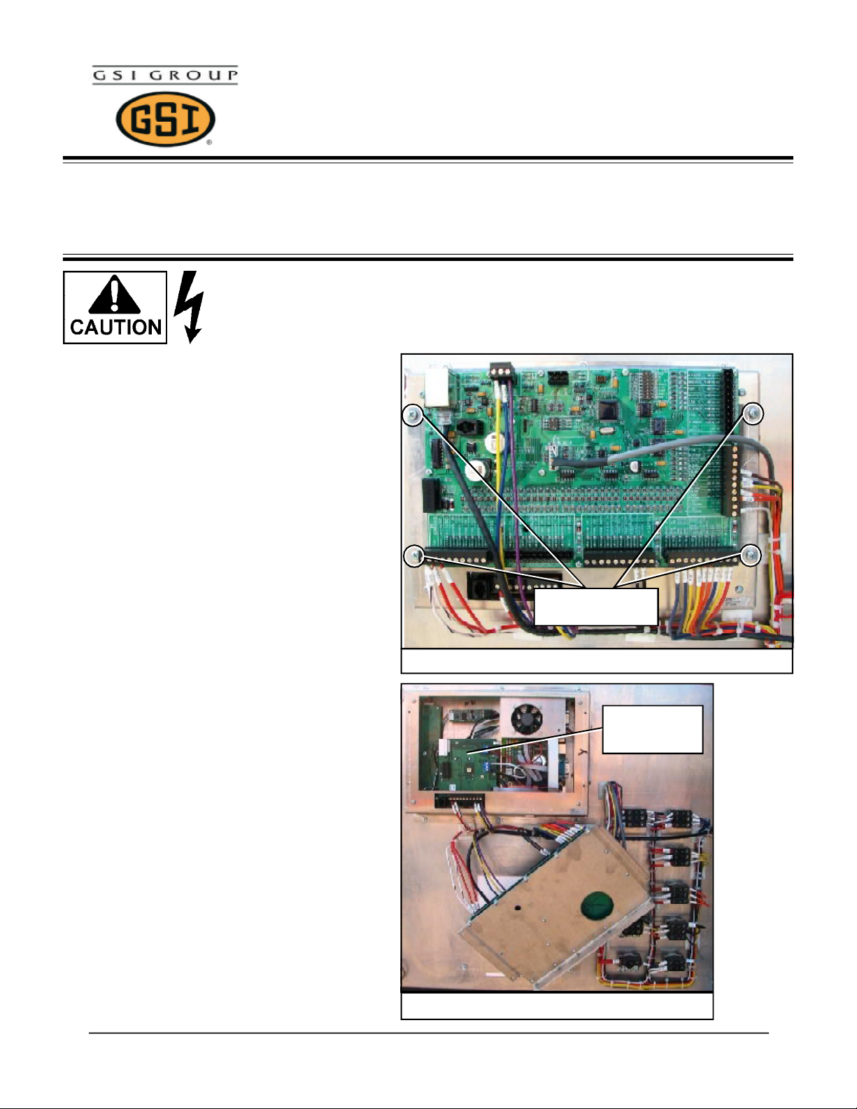
Step 1: Open the switch panel on the lower
control box and locate the touch screen computer
on back side of the switch panel (see figure A).
PNOT-305
Step 2: Remove the 4 phillips head screws shown
in figure A. After the screws have been removed
gently allow the circuit board to hang by the wires
that are connected to it (see figure B).
Step 3: After screws are removed and the inner
part of the touch screen computer is exposed
locate the internal touch control board (see figure
B).
Remove 4 phillips
head screws
Figure A: Touch screen computer.
Internal touch
control board
Figure B: After screws removed.
PNOT-305 1
Grain Systems • 1004 E. Illinois St. • Box 20 • Assumption, IL 62510
Phone: 217-226-4421 • Fax: 800-800-5329
Page 2
Product Notification
Vision Touch Control Board Fuse
Replacement Instructions
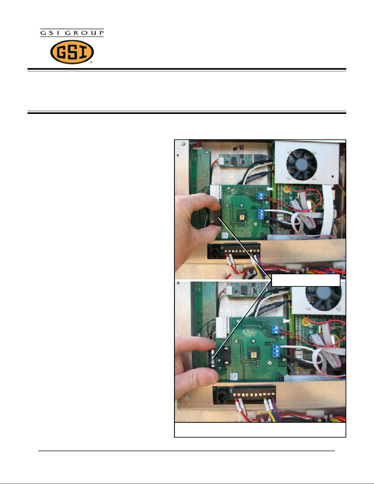
Step 4: Locate the 5amp fuse holder and pull the
fuse out (see figure C). If you DO NOT see a
fuse, then procede to Step 4A on the next page.
Occasionally the fuse may be difficult to pull the
first time. The easiest way to pull the fuse in this
instance is to use the thumb and index finger and
hold it as shown in figure C and pull the fuse using
a rocking motion.
PNOT-305
Step 5: Replace the fuse with a new one (part no.
E300-1013) and reassemble the touch control
computer.
5 amp Fuse
Figure C: Replace fuse.
Grain Systems • 1004 E. Illinois St. • Box 20 • Assumption, IL 62510
Phone: 217-226-4421 • Fax: 800-800-5329
PNOT-3052
Page 3

Product Notification
Vision Touch Control Board Fuse
Replacement Instructions
Step 4A: Remove the 4 phillips head screws and
remove the computer housing.
PNOT-305
Remove 4 phillips
head screws
Step 5A: Remove the plug shown in figure E
(Note the white wire is on bottom).
Remove the 4 phillips head screws that hold the
internal touch control board. (see figure E)
Figure D: Remove the computer housing.
Remove plug
Remove 4 phillips
head screws
Figure E: Turn internal touch screen board over.
PNOT-305 3
Grain Systems • 1004 E. Illinois St. • Box 20 • Assumption, IL 62510
Phone: 217-226-4421 • Fax: 800-800-5329
Page 4

Product Notification
Vision Touch Control Board Fuse
Replacement Instructions
Step 6A: Flip the internal touch screen board over
as shown in figure F. Locate the 5amp fuse holder
and replace the fuse.
Occasionally the fuse may be difficult to pull the
first time. The easiest way to pull the fuse in this
instance is to use the thumb and index finger and
hold it as shown in figure C on page 2 and pull
the fuse using a rocking motion.
PNOT-305
5 amp Fuse
Figure F: Replace fuse.
Grain Systems • 1004 E. Illinois St. • Box 20 • Assumption, IL 62510
Phone: 217-226-4421 • Fax: 800-800-5329
PNOT-3054
 Loading...