

Page 1
PNEG-900
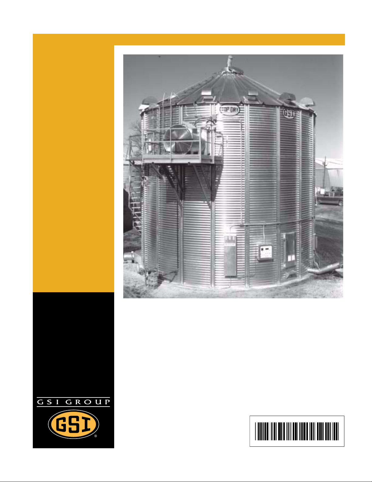
Series 2000 Autoflow
Fan/Heater and Control
Installation Instructions
Installation Manual
PNEG-900
Date: 02-07-13
Page 2

This equipment shall be installed in accordance with the current INSTALLATION CODES FOR
GAS BURNING APPLICANCES AND EQUIPMENT, CAN1_B149.1 and B149.2 or applicable
provincial regulations which should be carefully followed in all cases. Authorities having
jurisdiction should be consulted before installations are made.
2PNEG-900 Series 2000 Autoflow Fan/Heater and Control Installation Instructions
Page 3

Table of Contents
Contents
Chapter 1 Safety .....................................................................................................................................................4
Safety Guidelines .................................................................................................................................. 4
Series 2000 Autoflow Installation and Operating Instructions ............................................................... 5
Safety Precautions .................................... ... .... .......................................... ... ........................................ 5
Safety Sign-Off Sheet ........................................................................................................................... 7
Chapter 2 Decals ....................................................................................................................................................8
Chapter 3 Installation ..........................................................................................................................................10
Fan/Heater Mounting ....................................... ... ... ... .......................................... .... ... ... ... ... ................ 10
Autoflow Control Box Mounting ........................................................................................................... 10
Series 2000 Autoflow Control Box Bolt Pattern ................................................................................... 12
Control Box Mounting .......................................................................................................................... 13
Fill System Control Box Bolt Pattern ................................................................................................... 14
Multi-Grain Temperature Sensor ............ ... ... .... ... ... ... .... ... .......................................... ... ... ... .... ... ......... 17
Grain Temperature Sensor Mounted to Leveling Band Post .............................................................. 18
Close-Up Detail of Grain Temperature Sensor Wiring ........................................................................ 19
Plenum Temperature Sensor .............................................................................................................. 20
Plenum High-Limit Installation ............................................................................................................. 21
Top Dry Plenum High-Limit Installation ............................................................................................... 22
Wet Supply Rotary Switch ................................................................................................................... 23
Storage Chamber High-Limit Rotary Switch Installation ..................................................................... 25
Drying Chamber Rotary Switches Mounted in Bin Roof ..................................................................... 27
Drying Chamber Low-Level Rotary Switch Installation ....................................................................... 28
Drying Chamber High-Level Rotary Switch Installation ...................................................................... 30
Drying Chamber Overflow Rotary Switch Installation ......................................................................... 31
Liquid Propane (LP) ........ .......................................... .... .......................................... ... ......................... 32
Natural Gas (NG) ................................................................................................................................ 33
Chapter 4 Electrical Power Supply .....................................................................................................................34
Conduit Runs ...................................................................................................................................... 34
Grounding ........................................................................................................................................... 35
Power Supply ...................................................................................................................................... 35
Transformer and Wiring Voltage Drop ................................................................................................ 35
Machine to Earth Grounding ............................................................................................................... 35
Proper Installation of Ground Rod ....................................................................................................... 36
Power/Motor Wiring ...................... .... ... ... ... ... ....................................................................................... 38
Electrical Load Information .................................................................................................................. 39
Autoflow to Master Fan/Heater Unit Interconnect ............................................................................... 41
Autoflow to Actuator Interconnect ....................................................................................................... 42
Autoflow to Wet Supply Rotary Switch Interconnect ........................................................................... 43
Autoflow to Storage Chamber Rotary Switch Interconnect ................................................................. 44
Autoflow to Drying Chamber Rotary Switches Interconnect ............................................................... 44
Autoflow to Fill System Control Box Interconnect ............................................................ ... .... ...........
Autoflow to Ground Interconnect ......................................................................................................... 47
Master to Slave Interconnect ................................. ... .... .......................................... ... ......................... 48
Slave to Slave Interconnect ................................................................................................................ 49
Battery Hook-Up .................................................................................................................................. 50
Dump Chute Cable Installation ........................................................................................................... 50
Chapter 5 Warranty ..............................................................................................................................................53
. 46
PNEG-900 Series 2000 Autoflow Fan/Heater and Control Installation Instructio ns 3
Page 4
1. Safety
This is the safety alert symbol. It is used to alert you
to potential personal injury hazards. Obey all safety
messages that follow this symbol to avoid possible
injury or death.
WARNING indicates a hazardous situation which, if not
avoided, could result in death or serious injury.
CAUTION, used with the safety alert symbol, indicates a
hazardous situation which, if not avoided, could result in
minor or moderate injury.
NOTICE is used to address practices not related to
personal injury.
DANGER indicates a hazardous situation which, if not
avoided, will result in death or serious injury.
Personnel operating or working around equipment should read this manual. This
manual must be delivered with the equipment to its owner. Failure to read this manual
and its safety instructions is a misuse of the equipment.
WARNING! BE ALERT!
Safety Guidelines
This manual contains information that is important for you, the owner/operator, to know and understand.
This information relates to protecting personal safety and preventing equipment problems. It is the
responsibility of the owner/operator to inform anyone operating or working in the area of this equipment
of these safety guidelines. To help you recognize this information, we use the symbols that are defined
below. Please read the manual and pay attention to these sections. Failure to read this manual and its
safety instructions is a misuse of the equipment and may lead to serious injury or death.
DANGER
WARNING
CAUTION
NOTICE
4PNEG-900 Series 2000 Autoflow Fan/Heater and Control Installation Instructions
Page 5

1. Safety
Series 2000 Autoflow Installation and Operating Instructions
Thank you for choosing a Top Dry Series 2000 Autoflow unit. It is designed to give excellent performance
and service for many years.
This manual describes the installation for all standard production Top Dry Series 2000 single fan,
multi-fan and 2000 Series Autoflow units. Different models are available for liquid propane or natural
gas fuel supply, with either 1 phase 230 volt or 3 phase 208, 220, 380, 460 or 575 volt electrical power.
Our foremost concern is your safety and the safety of others associated with this equipment. We want to
keep you as a customer. This manual is to help you understand safe operating procedures and some
problems that may be encountered by the operator and other personnel.
As owner and/or operator, it is your responsibility to know what requirements, hazards, and precautions
exist and to inform all personnel associated with the equipment or in the area. Safety precautions may be
required from the personnel. Avoid any alterations to the equipment. Such alterations may produce a very
dangerous situation where SERIOUS INJURY or DEATH may occur.
This equipment shall be installed in accordance with the current installation codes and applicable
regulations, which should be carefully followed in all cases. Authorities having jurisdiction should be
consulted before installations are made.
Safety Precautions
READ THESE INSTRUCTIONS BEFORE OPERATION AND SERVICE
SAVE FOR FUTURE REFERENCE
1. Read and understand the operating manual before trying to operate the dryer.
2. Power supply should be OFF for service of electrical components. Use CAUTION in checking voltage
or other procedures requiring power to be ON.
3. Check for gas leaks at all gas pipe connections. If any leaks are detected, DO NOT operate the dryer.
Shut down and repair before further operation.
4. NEVER attempt to operate the dryer by jumping or otherwise bypassing any safety devices
on the unit.
5. Set pressure regulator to avoid excessive gas pressure applied to burner during ignition and when
burner is in operation. DO NOT exceed maximum recommended drying temperature.
6. Keep the dryer clean. DO NOT allow fine material to accumulate in the plenum or drying chamber.
7. Use CAUTION in working around high speed fans, gas burners, augers and auxiliary conveyors
which can START AUTOMATICALLY.
8. DO NOT operate in any area where combustible material will be drawn into the fan.
9. BEFORE attempting to remove and re-install any propeller, make certain to read the recommended
procedure listed within the servicing section of the manual.
10. Clean grain is easier to dry. Fine material increases resistance to airflow and requires removal of
extra moisture.
Proper Use of Product
This product is intended for the use of drying small grains only. Any other use is a misuse of the product.
This product has sharp edges. These sharp edges may cause serious injury. To avoid injury handle sharp
edges with caution and use proper protective clothing and equipment at all times.
Guards are removed for illustration purposes only. All guard s must be in place before and during operation.
PNEG-900 Series 2000 Autoflow Fan/Heater and Control Installation Instructions 5
Page 6
1. Safety
CAUTION
Keep the dryer clean. Do not allow fine material to accumulate in the plenum
chamber or surrounding the outside of the dryer.
Use Caution in the Operation of this Equipment
This dryer is designed and manufactured with operator safety in mind. However, the very nature of a grain
dryer having a gas burner, high voltage electrical equipment and high speed rotating parts, presents
hazards to personnel which cannot be completely safeguarded against withou t interfering with the efficient
operation of the dryer and reasonable access to its components.
Use extreme caution in working around high speed fans, gas-fired heaters, augers and auxiliary
conveyors, which may start without warning when the dryer is operating on automatic control.
Continued safe, dependable operation of automatic equipment depends, to a great degree, upon
the owner. For a safe and dependable drying system, follow the recommendations within this manual and
make it a practice to regularly inspect the unit for any developing problems or unsafe conditions.
Take special note of the Safety Precautions on Page 5 before attempting to operate the dryer.
6PNEG-900 Series 2000 Autoflow Fan/Heater and Control Installation Instructions
Page 7

1. Safety
Safety Sign-Off Sheet
As a requirement of O.S.H.A., it is necessary for the employer to train the employee in the safe operating
and safety procedures for this equipment. This sign-off sheet is provided for your convenience and
personal record keeping. All unqualified persons are to stay out of the work area at all times. It is strongly
recommended that another qualified person who knows the shut down procedure be in the area in the
event of an emergency.
Date Employee Name Supervisor Name
PNEG-900 Series 2000 Autoflow Fan/Heater and Control Installation Instructions 7
Page 8
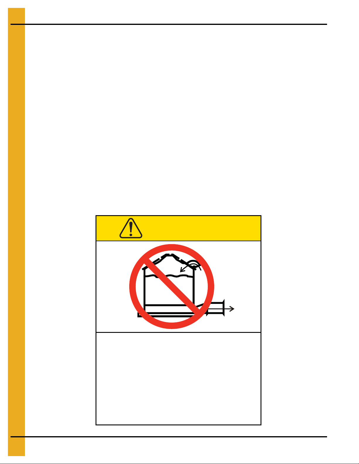
2. Decals
Excessive vacuum (or pressure) may
damage roof. Use positive aeration
system. Make sure all roof vents are
open and unobstructed. Start roof
fans when supply fans are started.
Do not operate when conditions exist
that may cause roof vent icing.
DC-969
CAUTION
GSI Group, Inc. 217-226-4421
The GSI recommends contacting your local power company and having a representative survey the
installation so the wiring is compatible with their system and adequate power is supplied to the unit.
Safety decals should be read and understood by all people in the grain handling area. The rotating blade,
fire warning decals and voltage danger decal must be displayed on the fan can. The decal DC-GBC-1A
shown on Page 9 should be present on the inside bin door cover of the 2 ring door, 24" porthole door cover
and the roof manway cover.
If a decal is damaged or is missing contact:
GSI Decals
1004 E. Illinois St.
Assumption, IL. 62510
Phone: 1-217-226-4421
A free replacement will be sent to you.
Roof Damage Warning and Disclaimer
The manufacturer does not warrant any roof damage caused by excessive vacuum or internal
pressure from fans or other air moving systems. Adequate ventilation and/or “makeup air” devices
should be provided for all powered air handling systems. The manufacturer does not reco mmend
the use of downward flow systems (suction). Severe roof damage can result from any block age of
air passages. Running fans during high humidity/cold weather conditions can cause air exhaust
or intake ports to freeze.
8PNEG-900 Series 2000 Autoflow Fan/Heater and Control Installation Instructions
Page 9
2. Decals
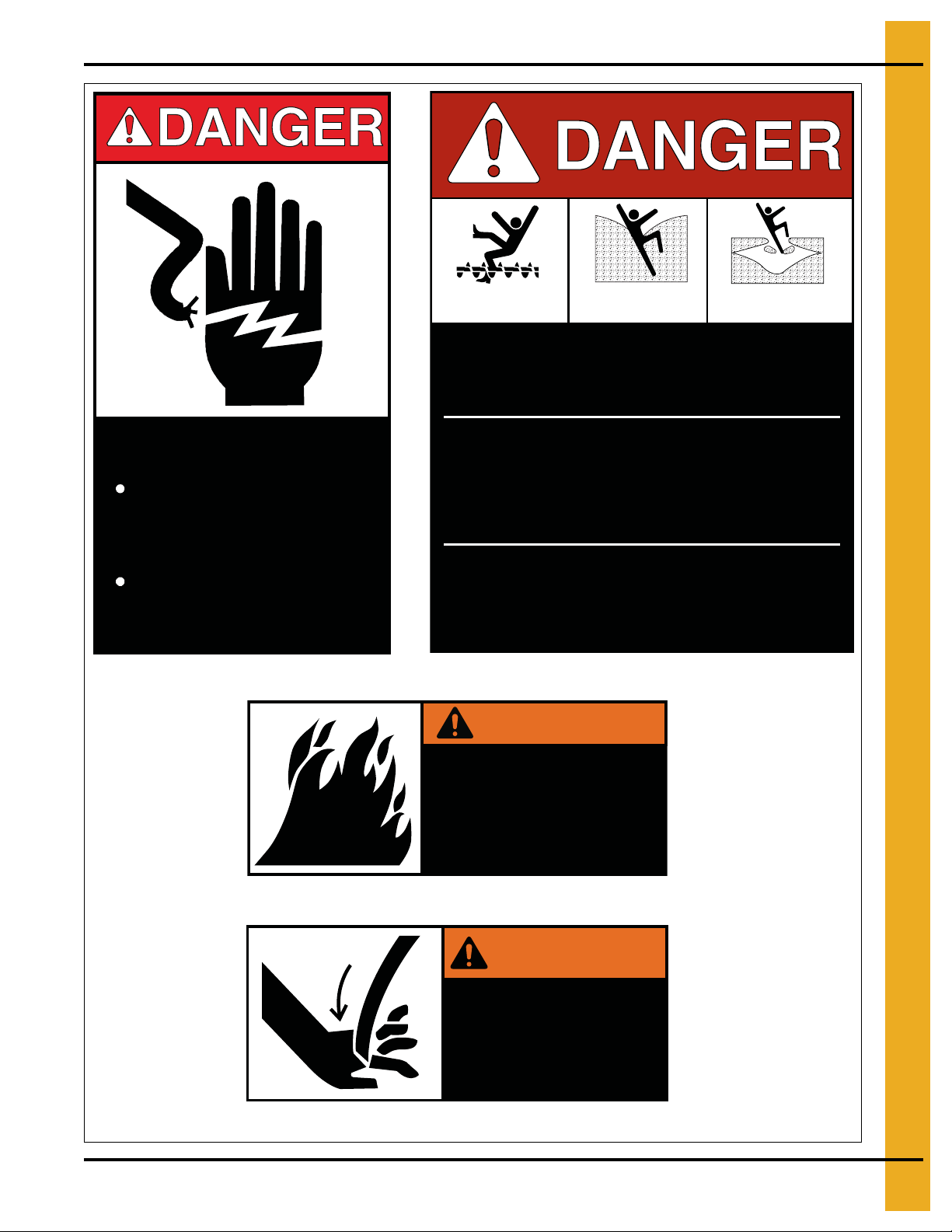
HIGH VOLTAGE.
Will cause serious
injury or death.
Lockout power
before servicing.
DC-1224
DC-1225
DC-1227
DC-GBC-1A
DC-1224
Rotating flighting will
kill or dismember.
Flowing material will
trap and suffocate.
Crusted material will
collapse and suffocate.
Keep clear of all augers.
DO NOT ENTER this bin!
If you must enter the bin:
1. Shut off and lock out all power.
2. Use a safety harness and safety line.
3. Station another person outside the bin.
4. Avoid the center of the bin.
5. Wear proper breathing equipment or respirator.
Failure to heed these
warnings will result in
serious injury or death.
DC-GBC-1A
WARNING
PNEG-900 Series 2000 Autoflow Fan/Heater and Control Installation Instructions 9
Flame and pressure beyond
door can cause serious
injury. Do not operate with
service door removed. Keep
head and hands clear.
DC-1227
WARNING
Stay clear of rotating
blade. Blade could start
automatically. Can cause
serious injury. Disconnect
power before servicing.
DC-1225
Page 10
3. Installation
Fan/Heater Mounting
NOTE: Do not install this control panel near any transformers or any other device that will produce an
electro magnetic field.
1. Inspect the fan platform for proper installation per instructions in the Top Dry erection manual.
2. Raise the Top Dry fan/heater units to the platform. Use the Table below to determine the height of
the platform from the base of the Top Dry unit.
3. Mount the Top Dry fan/heater units to the bin entrance sheets. Fan legs should set on the platform.
Top Dry Bin Eave Height
# of Rings Eave Height
5 18'-5"
622'-1"
7 25'-9"
829'-5"
9 33'-1"
10 36'-9"
11 40'-5"
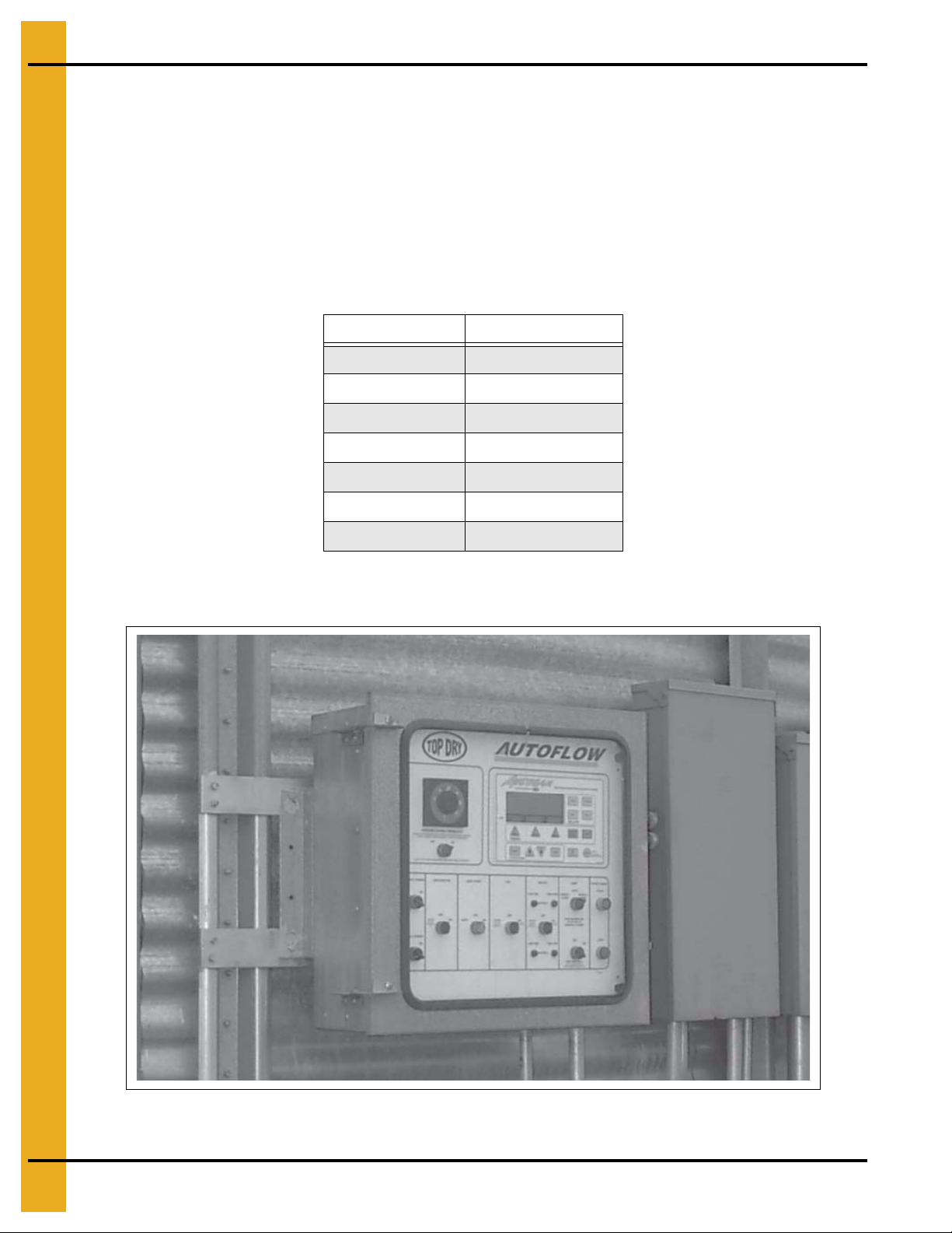
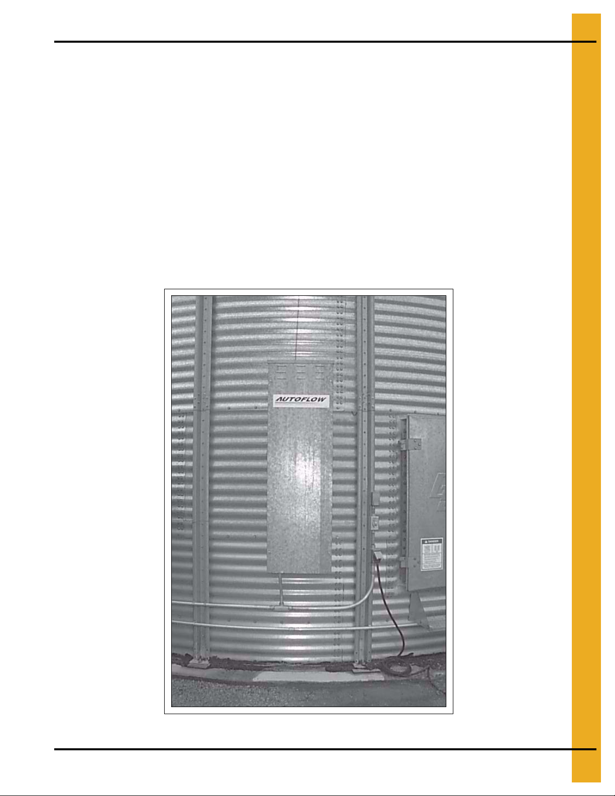
Autoflow Control Box Mounting
Figure 3A Autoflow Control Box Mounted on Bin
10 PNEG-900 Series 2000 Autoflow Fan/Heater and Control Installation Instructions
Page 11

3. Installation
1. The Autoflow control box should be mounted at eye-level. Make sure to mount the Autoflow control
box so that the fan/heater unit(s) are in view.
2. Keep in mind that wire will be used to interconnect the Autoflow control box with the fan/heater unit(s),
fill system control box, actuator and all rotary switches.
3. Use the hole pattern in Figure 3C on Page 12 to drill holes for mounting the Autoflow control box.
Figure 3B Component Placement
PNEG-900 Series 2000 Autoflow Fan/Heater and Control Installation Instructions 11
Page 12
3. Installation
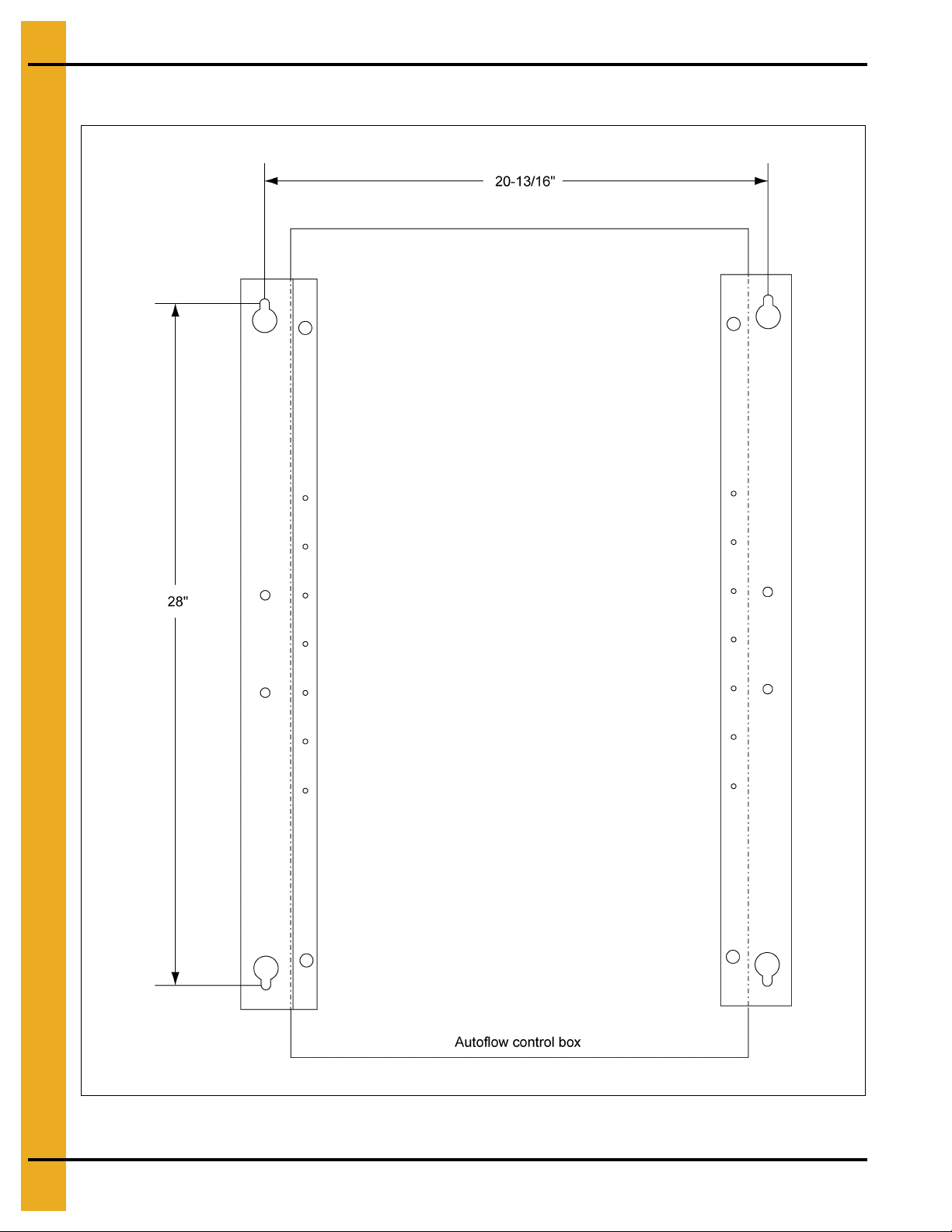
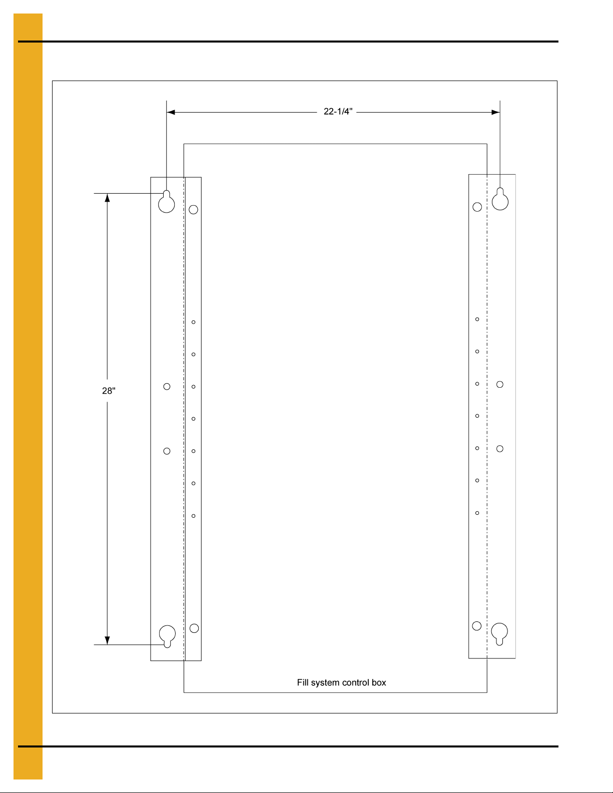
Series 2000 Autoflow Control Box Bolt Pattern
Figure 3C Illustration of the bolt pattern for the autoflow control box.
12 PNEG-900 Series 2000 Autoflow Fan/Heater and Control Installation Instructions
Page 13
3. Installation
Control Box Mounting
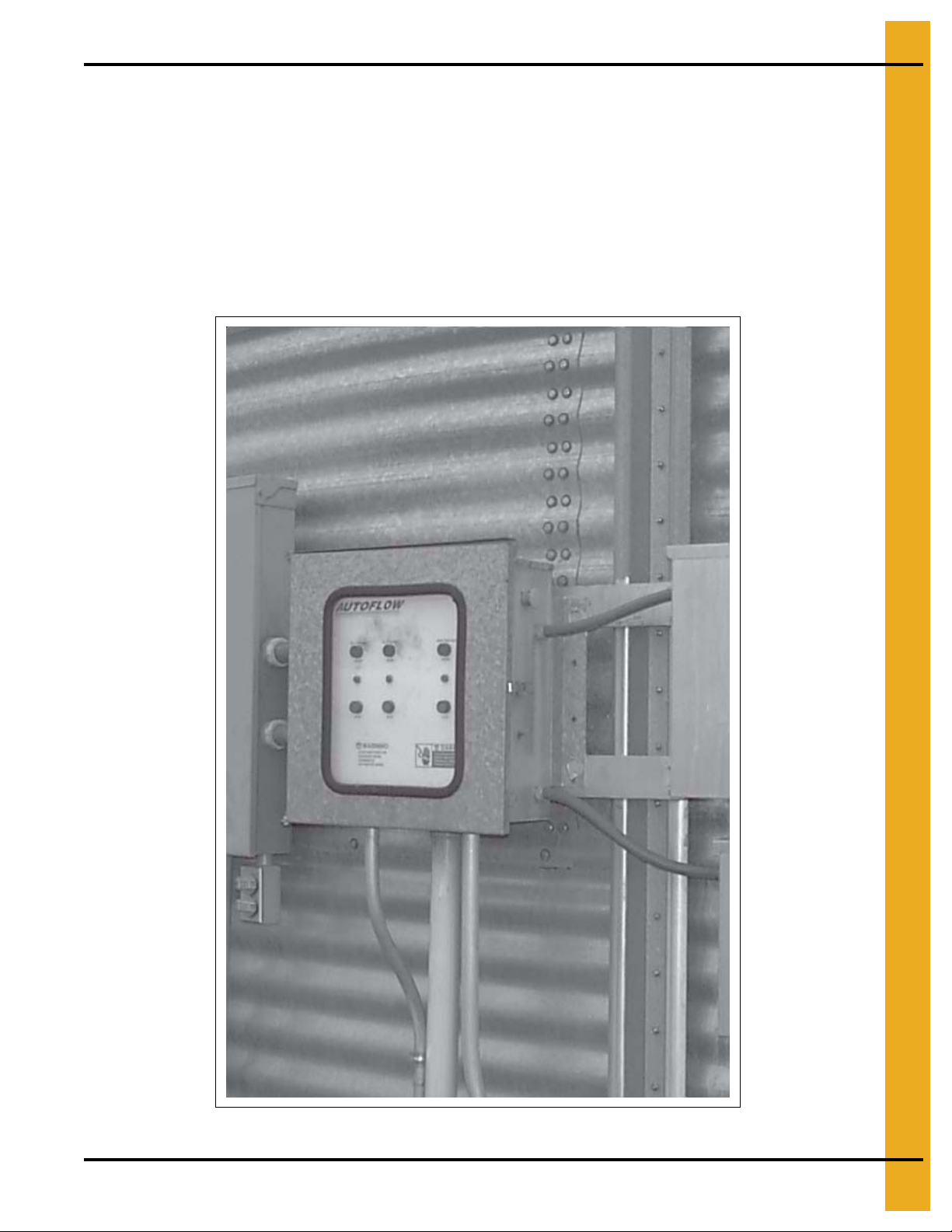
Fill System Control Box Mounting
1. The fill system control box should be mounted at eye-level. Make sure to install the fill system control
box so that the fill system(s) and aeration fan are in view.
2. Keep in mind that wire will be used to interconnect the fill system control box with the Autoflow control
box; and, that power wires will have to be run from the entrance panel to the fill system control box
to power the fill system and aeration fan motors, which will also run from the fill system control box.
3. Use the pattern in Figure 3E on Page 14 to drill holes for the fill system control box.
Figure 3D Fill System Control Box Mounted to Bin
PNEG-900 Series 2000 Autoflow Fan/Heater and Control Installation Instructions 13
Page 14
3. Installation
Fill System Control Box Bolt Pattern
Figure 3E Illustration of the bolt pattern for the fill system control box.
14 PNEG-900 Series 2000 Autoflow Fan/Heater and Control Installation Instructions
Page 15
3. Installation
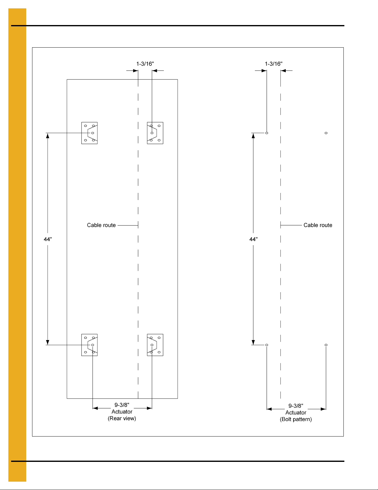
Actuator Control Box Mounting
1. Mark the third sidewall ring from the ground to indicate the cable path if dump chutes and cable are
already installed.
2. Make sure that all dump chutes and chains are EVENLY adjusted so that when one chute is level the
others are level as well.
3. Keep in mind that wire will be used to interconnect the actuator control box with the Autoflow control
box; and, that a 110V power supply will need to run from the entrance panel to the actuator control
box to power the 24V DC battery charger.
4. Use the pattern in Figure 3G on Page 16 to drill holes for the actuator control box.
5. If the horizontal seam bolts are within 1" horizontally of the hole pattern shown, existing holes may
be used to attach the actuator.
6. Use four (4) 5/16" x 1-1/4" bin bolts and washers with bolt heads to the inside of the bin.
7. Do not attach the dump chute cable to the actuator at this time. The cable should not be installed until
after the actuator unit is completely wired and tested.
Figure 3F Actuator Control Box Mounted to Bin
PNEG-900 Series 2000 Autoflow Fan/Heater and Control Installation Instructions 15
Page 16
3. Installation
Actuator Control Box Mounting (Continued)
Figure 3G Bolt Pattern to Drill Holes for the Actuator Control Box
16 PNEG-900 Series 2000 Autoflow Fan/Heater and Control Installation Instructions
Page 17
3. Installation
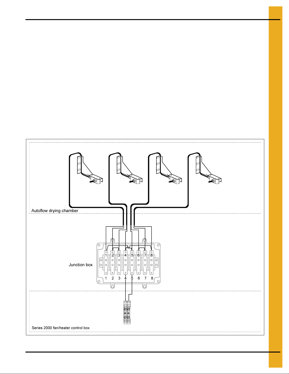
Multi-Grain Temperature Sensor
1. Remove the two (2) wires attached to the grain temperature sensor connected to terminal #22 and
terminal #23 in the fan control box.
2. Mount the four (4) grain temperature sensor brackets evenly around the drying chamber on outside
leveling band posts. (See Figure 3I on Page 18.)
3. Mount the brackets with bin bolts so that the sensor is 8-1/2" above the floor sheet rib for Auto drying
mode and 10-1/2" above the floor sheet rib for Batch drying mode . For AUTO drying, the bottom hole
in the mounting bracket should align with the third hole from the bottom of the leveling band post.
For BATCH drying, the bottom hole in the mounting bracket should align with the fourth hole from the
bottom of the leveling band post.
4. Wire tie the cords so they feed up the leveling band post and across the top leveling band.
5. Route the cords through the space between the roof and the top sidewall sheet. There should be
enough on all temperature sensor brackets to exit the drying chamber at the same place.
6. Route the cords into the junction box after the junction box has been mounted to the bin.
7. Wire the four (4) temperature sensors as shown in Figure 3H and on Page 19.
Figure 3H Illustration of the grain temperature sensor interconnection.
PNEG-900 Series 2000 Autoflow Fan/Heater and Control Installation Instructions 17
Page 18

3. Installation
Grain Temperature Sensor Mounted to Leveling Band Post
Figure 3I Illustration of grain temperature sensor mounted on outside leveling band post.
Height of Sensor Bracket
Drying Mode Height of “X”
Auto 8-1/2"
Batch 10-1/2"
18 PNEG-900 Series 2000 Autoflow Fan/Heater and Control Installation Instructions
Page 19

Close-Up Detail of Grain Temperature Sensor Wiring
3. Installation
Figure 3J
PNEG-900 Series 2000 Autoflow Fan/Heater and Control Installation Instructions 19
Page 20

3. Installation
Plenum Temperature Sensor
The plenum temperature sensor is the small grey PVC junction box attached by a cord to the fan/heater
control box on the master fan/heater unit.
1. On either side of the fan/heater, drill one 3/4" hole even with the fan/heater unit in a valley on the
bin sidewall.
2. Insert the probe through the 3/4" hole.
3. Position the housing so the cord exits the housing horizontally and the tabs fall on the sidewall peaks.
4. Use two (2) self-drilling screws to mount the housing to the bin sidewall.
5. Caulk between the housing and the sidewall to seal the gaps.
IMPORTANT: If the top dry is a 2 fan unit, do not mount the plenum temperature sensor between the
2 fan/heater units.
Figure 3K Plenum Temperature Sensor on the Bin Sidewall
20 PNEG-900 Series 2000 Autoflow Fan/Heater and Control Installation Instructions
Page 21

Plenum High-Limit Installation
3. Installation
Figure 3L 30' Top Dry Layout Plenum High-Limit
PNEG-900 Series 2000 Autoflow Fan/Heater and Control Installation Instructions 21
Page 22

3. Installation
Top Dry Plenum High-Limit Installation
1. Assemble two (2) pieces of conduit together with coupler.
2. Mount conduit clamps to conduit assembly.
3. Locate conduit assembly on the bottom of a rafter at least 2' to one side of the fan entrance. Do not
install between 2 fan entrances.
4. Mark bin wall where conduit will pass through and drill a hole just large enough to allow the conduit
to pass through. Seal hole with caulking when complete.
5. Install white PVC box assembly on outside of bin wall.
6. Insert 10' capillary into conduit assembly.
7. Connect SJO cord to high-limit and connect wires to terminal #20 and terminal #21 on the master fan
terminal strip. These terminals are J7-08 and J7-03.
Figure 3M
22 PNEG-900 Series 2000 Autoflow Fan/Heater and Control Installation Instructions
Page 23

3. Installation
Wet Supply Rotary Switch
1. Drill a 2" diameter hole through the hopper bottom. If a flat bottom bin is being used for a wet storage
tank the Wet Supply Rotary switch would be mounted 45° up the sidewall from the center of the bin.
Example: If the wet storage bin is 18' in diameter then the Wet Supply Rotary switch would be
mounted 9' up the sidewall.
2. If the bin is 2.66" corrugation, the hole should be centered on an outside hill.
3. If the bin is 4.00" corrugation, the hole should be centered on an outside valley.
4. Use the mounting plate as a pattern and drill four (4) 3/8" holes through the sidewall at the switch
location so the place can be bolted to the bin.
5. Add foam weather strip around the top and side of the mounting plate.
6. Caulk the underside of the mounting plate, on all sides of the 2" hole and where the plate meets
the bin.
7. Bolt the mounting plate to the sidewall.
8. Attach the flex coupling to the rotary switch power pack using a roll pin.
9. Attach the 1 vane paddle to the flex coupling as shown in Figure 3N on Page 24.
10. Apply teflon tape or pipe sealant (not included) to the rotary switch power pack threads and thread
the rotary switch power pack into the mounting plate coupling.
11. Make sure that the conduit hole is facing down.
PNEG-900 Series 2000 Autoflow Fan/Heater and Control Installation Instructions 23
Page 24

3. Installation
Figure 3N
24 PNEG-900 Series 2000 Autoflow Fan/Heater and Control Installation Instructions
Page 25

3. Installation
Storage Chamber High-Limit Rotary Switch Installation
1. Drill a 2" diameter hole through the sidewall 3' below the fan/heater.
2. If the bin is 2.66" corrugation, the hole should be centered on an outside hill.
3. If the bin is 4.00" corrugation, the hole should be centered on an outside valley.
4. Use the mounting plate as a pattern and drill four (4) 3/8" holes through the sidewall at the switch
location so the plate can be bolted to the bin.
5. Add foam weather strip around the top and side of the mounting plate.
6. Caulk the underside of the mounting plate, on all sides of the 2" hole and where the plate meets
the bin.
7. Bolt the mounting plate to the sidewall.
8. Attach the flex coupling to the rotary switch power pack using a roll pin.
9. Attach the 1 vane paddle to the flex coupling as shown in Figure 3P on Page 26.
10. Apply teflon tape or pipe sealant (not included) to the rotary switch power pack threads and thread
the rotary switch power pack into the mounting plate coupling.
11. Make sure that the conduit hole is facing down.
Figure 3O Storage Chamber Rotary Switch
PNEG-900 Series 2000 Autoflow Fan/Heater and Control Installation Instructions 25
Page 26

3. Installation
Figure 3P
26 PNEG-900 Series 2000 Autoflow Fan/Heater and Control Installation Instructions
Page 27

3. Installation
Drying Chamber Rotary Switches Mounted in Bin Roof
The three (3) Drying Chamber rotary switches are used by the Series 2000 Autoflow to monitor the
location of grain in the drying chamber. The rotary switch with the shortest shaft extension is the Drying
Chamber Overflow Rotary switch. It is used as a safety in the event the Chamber High-Level Rotary switch
fails. The rotary switch with the longest extension is the Drying Chamber Low-Level Rotary switch. It is
used to inform the computer when the peak has been covered with grain so the drying process can begin;
and, will shut down if the drying chamber empties unexpectedly. The third rotary switch is the Drying
Chamber High-Level Rotary switch. It is used to inform the dryer when the drying chamber is full so loading
can stop.
When mounting the Drying Chamber Rotary switches some foresight is needed. The Drying Chamber
Rotary switches should be located in close proximity to one another to lessen the amount of conduit and
wiring required. The rotary switches should also be mounted so that they are located in an area of the
drying chamber that fills evenly with the rest of the drying chamber. The component placement o n Page 11
shows the placement of the Drying Chamber Rotary switches in relation to the fill system #1 transport
auger/downspout.
The rotary switches should NOT be located in a part of the d rying chamber that fills unevenly with the rest
of the drying chamber. If the area of the drying chamber where the rotary switches are located fills faster
that the rest of the drying chamber the drying chamber will not fill to capacity and uneven drying will result.
If the area of the drying chamber where the rotary switches are located fills slower than the rest of the
drying chamber an overflow situation may occur.
It is very critical that the drying chamber fill evenly and that the grain falls from fill system #1 directly onto
the perforated cone in the drying chamber.
Figure 3Q
PNEG-900 Series 2000 Autoflow Fan/Heater and Control Installation Instructions 27
Page 28

3. Installation
Top Dry Bin Diameter “A”
18'-24' 23-1/2"
27' and 30' 19"
36' 31"
Drying Chamber Low-Level Rotary Switch Installation
1. Drill a 2" diameter hole through the roof panel at the location shown in Figure 3R. See component
placement on Page 11 for proper placement in relation to fill auger.
2. Use the mounting plate as a pattern and drill four (4) 3/8" holes through the roof panel at the switch
location so the plate can be bolted to the roof.
3. Attach the flex coupling to the rotary switch power pack using a roll pin.
4. Apply teflon tape or pipe sealant (not included) to the rotary switch power pack threads and thread
the rotary switch power pack into the mounting plate coupling.
5. Make sure that the conduit hole is facing towards the eave.
6. Caulk the underside of the mounting plate and on all sides of the 2" hole.
7. Bolt the assembly to the roof panel.
8. Attach the shaft extension according to Figure 3S on Page 29.
9. Apply teflon tape or pipe sealant (not included) to the shaft guard.
10. Thread to underneath side of mounting plate.
11. Add the 1/4" drilled coupling to the shaft extension using the cotter pin.
12. Attach the 1 vane paddle to the flex coupling as shown in Figure 3S on Page 29.
28 PNEG-900 Series 2000 Autoflow Fan/Heater and Control Installation Instructions
Figure 3R
Page 29

3. Installation
Figure 3S
PNEG-900 Series 2000 Autoflow Fan/Heater and Control Installation Instructions 29
Page 30

3. Installation
Drying Chamber High-Level Rotary Switch Installation
1. Drill a 2" diameter hole through the roof panel at the location shown in Figure 3R on Page 28.
See component placement on Page 11 for proper placement in relation to fill auger.
2. Assemble 1/4" shaft to rotary switch with 1/4" coupler and rolled pins.
3. Screw 1-1/4" pipe coupler to bottom of rotary switch.
4. Insert 1-1/4" pipe through adjustable roof mount weldment. Leave 1-1/4" pipe sticking out the top of
the weldment 3" as shown in Figure 3T.
5. Install switch assembly through 2" hole in roof.
6. Install paddle to 1/4" shaft assembly with coupler and rolled pins.
Figure 3T
30 PNEG-900 Series 2000 Autoflow Fan/Heater and Control Installation Instructions
Page 31

3. Installation
Drying Chamber Overflow Rotary Switch Installation
1. Drill a 2" diameter hole through the roof panel at the location shown in Figure 3R on Page 28.
See component placement on Page 11 for proper placement in relation to fill auger.
2. Use the mounting plate as a pattern and drill four (4) 3/8" holes through the roof panel at the switch
location so the plate can be bolted to the roof.
3. Attach the flex coupling to the rotary switch power pack using a roll pin.
4. Apply teflon tape or pipe sealant (not included) to the rotary switch power pack threads and thread
the rotary switch power pack into the mounting plate coupling.
5. Make sure that the conduit hole is facing towards the eave.
6. Caulk the underside of the mounting plate and on all sides of the 2" hole.
7. Bolt the assembly to the roof panel.
8. Attach the 3 vane paddle to the flex coupling as shown in Figure 3U.
Figure 3U
PNEG-900 Series 2000 Autoflow Fan/Heater and Control Installation Instructions 31
Page 32

3. Installation
NOTICE
Do not use tanks which have previously been used for ammonia or fertilizer
solutions. These substances are extremely corrosive and will damage fuel supply
and burner parts.
WARNING
Do not use flame for leak testing.
Liquid Propane (LP)
Top Dry dryers have internal vaporizers and are designed to operate on liquid draw from the supply tank.
Avoid using propane supply tanks that have been used for vapor draw for long periods of time. When using
liquid draw systems, any moisture that may be present in tanks or lines may freeze when the system is
used in cold weather. To avoid this situation, purge the system with methanol.
Because the vaporizer coil may need to be adjusted during operation flexible hose suitable f or LPs should
be used for the final field connection.
See the below “Fuel Systems and Recommendations Chart” for liquid propane (LP) to determine the
correct size line to run from the tank to the dryer. Have a qualified gas service person inspect the
installation to be sure that everything is installed according to local codes and ordinances.
After installation is complete, check all connections for leaks with liquid detergent or comparable. Wear
rubber gloves and eye protection. Avoid contact with liquid propane.
Figure 3V LP Line Field Connection
Fuel System Specifications and Recommendations Liquid Propane (LP)
Dryer
Fan Size
36" 15 5 Million 54 1/2" 21/64" 1 lb. 15 lbs.
40" 15 5.5 Million 60 1/2" 11/32" 1 lb. 15 lbs.
42" 30 9 Million 95 1/2" 0.328" 1 lb. 15 lbs.
42" 40 9.5 Million 104 3/4" 29/64" 1 lb. 15 lbs.
32 PNEG-900 Series 2000 Autoflow Fan/Heater and Control Installation Instructions
Dryer
Horsepower
Maximum Heat
Capacity BTU
per Hour
Maximum Fuel
Flow Gallons
per Hour
Minimum
Line Size
Orifice Size
Minimum
Operating
Pressure
Maximum
Operating
Pressure
Page 33

3. Installation
WARNING
Do not use flame for leak testing.
Natural Gas (NG)
This dryer is designed to operate on natural gas. Natural gas units have a larger orifice to accommodate
lower pressures sometimes found with natural gas and do not have vaporizer coils like liquid propane
units. A regulated pressure of 10 PSI minimum, 30 PSI maximum must be provided at the field connection
point on the fan/heater unit, with gas available in sufficient volume to maintain the operating pressure.
See the below “Fuel Systems and Recommendations Chart” for natural gas (NG) to determine the correct
size line to run to the dryer. Have a qualified gas service person inspect the installation to be sure
everything is installed according to local codes and ordinances.
After installation is complete, check all connections for leaks with liquid detergent or comparable. Wear
rubber gloves and eye protection.
Figure 3W NG Line Field Connection
Fuel System Specifications and Recommendations Natural Gas (NG)
Dryer
Fan Size
36" 15 5 Million 5280 2" 1/2" 1 lb. 7 lbs.
40" 15 5.5 Million 5965 2" 17/32" 1 lb. 7 lbs.
42" 30 9 Million 9536 2" 43/64" 1 lb. 7 lbs.
42" 40 9.5 Million 10445 2" 45/64" 1 lb. 7 lbs.
PNEG-900 Series 2000 Autoflow Fan/Heater and Control Installation Instructions 33
Dryer
Horsepower
Maximum Heat
Capacity BTU
per Hour
Maximum Fuel
Flow Cubic Ft.
per Hour
Minimum
Line Size
Orifice Size
Minimum
Operating
Pressure
Maximum
Operating
Pressure
Page 34

4. Electrical Power Supply
Conduit Runs
Control Wires
Run #1 Autoflow control box to master fan/heater control box.
Five (5) - Control wires 16 gauge minimum. (NOTE: A shielded two (2) conductor 16 gauge cable
should be used for the network connections.)
Run #2 Autoflow control box to actuator control box.
Five (5) - Control wires 16 gauge minimum.
Run #3 Autoflow control box to wet supply rotary switch.
Four (4) - Control wires 16 gauge minimum.
Run #4 Autoflow control box to storage chamber rotary switch.
Five (5) - Control wires 16 gauge minimum.
Run #5 Autoflow control box to drying chamber rotary switches.
Six (6) - Control wires 16 gauge minimum.
Run #6 Autoflow control box to fill system control box (if applicable).
Eleven (11) - Control wires 16 gauge minimum.
Run #7 Master fan/heater control box to slave fan/heater control box.
Four (4) - Control wires 16 gauge minimum. (NOTE: A shielded two (2) co nductor 16 gauge cable
should be used for the network connections.)
Run #8 Slave fan/heater #1 control box to slave fan/heater #2 control box.
Four (4) - Control wires 16 gauge minimum. (NOTE: A shielded two (2) co nductor 16 gauge cable
should be used for the network connections.)
Power/Motor Wires
Run #1 Entrance panel to master fan/heater control box (for fan motor).
Run #2 Entrance panel to slave fan/heater control boxes (if applicable, for fan motor).
Run #3 Entrance panel to fill system control box (if applicable).
1. For fill system #1 motor starter.
2. For fill system #2 motor starter (if applicable).
3. For aeration fan motor starter.
Run #4 Fill system control box to fill system #1 motor.
Run #5 Fill system control box to fill system #2 motor (if applicable).
Run #6 Fill system control box to aeration fan motor.
Run #7 Entrance panel to actuator control box.
1. 110V AC, 110V N, Ground wire for battery charger.
34 PNEG-900 Series 2000 Autoflow Fan/Heater and Control Installation Instructions
Page 35

4. Electrical Power Supply
Grounding
All control boxes should be properly grounded with a ground lug mounted in each control box.
Power Supply
An adequate power supply and proper wiring are important factors to achieve maximum p erformance and
long life of the dryer. Electrical service must be adequate enough to prevent low voltage damage to motors
and control circuits. (See electrical load information on Page 39.)
Transformer and Wiring Voltage Drop
It is necessary to know the distance from the unit to the available transformer and the horsepower of the
fan unit. Advise the service representative of your local power supplier that an additional load will be
placed on the line. Each fan motor should be wired through a fused or circuit breaker disconnect switch.
Check on KVA rating of transformers, considering total horsepower load. The power supply wiring, main
switch equipment and transformers must provide adequate motor starting and operating voltage. Voltage
drop during motor starting should not exceed 14% of normal voltage and after motor is running at full
speed it should be within 8% of normal voltage. Check electrical load information on Page 39 for HP
ratings and maximum amp loads to properly size wire and fusing elements. Standard electrical safety
practices and codes should be used. (Refer to National Electrical Code Standard Handbook by National
Fire Protection Association.)
Machine to Earth Grounding
It is very important that a machine to earth ground rod be installed at the fan. This is true even if there is
a ground at the pole 15' away. Place the ground rod that comes standard, within 8' of the dryer and attach
it to the dryer control panel with at least a #6 solid, bare, copper ground wire and the clamp provided.
The grounding rod located at the power pole will not provide adequate grounding for the dryer. Th e proper
grounding will provide additional safety in case of any short and will ensure long life of all circuit boards
and the ignition system. The ground rod must be in accordance with local requirements.
PNEG-900 Series 2000 Autoflow Fan/Heater and Control Installation Instructions 35
Page 36

4. Electrical Power Supply
Dig a hole large enough to hold
1 or 2 gallons of water. Work the
ground rod into the earth until it
is completely in the ground.
Proper Installation of Ground Rod
The ground rod should not be driven into dry ground.
Follow these instructions for proper installation:
1. Dig a hole large enough to hold 1 to 2 gallons of water.
2. Fill hole with water.
3. Insert rod through water and jab it into the ground.
4. Continue jabbing the rod up and down. The water will work its way down the hole, making it possible
to work the rod completely into the ground. This method of installing the rod gives a good conductive
bond with the surrounding soil.
5. Connect the bare copper ground wire to the rod with the proper ground rod clamp. (See Figure 4B
on Page 37.)
6. Connect the bare copper ground wire to the fan control boxes with a grounding lug.
7. Ground wire must not have any breaks or splices.
Figure 4A
36 PNEG-900 Series 2000 Autoflow Fan/Heater and Control Installation Instructions
Page 37

4. Electrical Power Supply
Figure 4B The Top Dry and Ground Rod Attachment Illustration
PNEG-900 Series 2000 Autoflow Fan/Heater and Control Installation Instructions 37
Page 38

4. Electrical Power Supply
NOTICE
Standard electrical safety procedures should be used. (Refer to the National
Electrical Code Standard Handbook by the National Fire Protection Association.)
A qualified electrician should make all electrical wiring installations. Follow all
local or national electrical safety standards and ordinances when installing
the equipment.
Power/Motor Wiring
The Figure 4C details the configuration for correct main power installation. Use the diagram in conjunction
with the electrical load information and wire size information provided. The diagram details the correct
main power installation for 220V 1 PH, 230V 3 PH, 460V 3 PH, 575V 3 PH and 380V 3 PH 50 Hz
power supplies.
On all 3 phase systems put the leg with the highest potential differe nce between that leg and ground (wild
or high voltage leg) on the center terminal (L2) at the motor starter.
Figure 4C Main Power Schematic
38 PNEG-900 Series 2000 Autoflow Fan/Heater and Control Installation Instructions
Page 39

4. Electrical Power Supply
Electrical Load Information
The Chart below provide information for the electrician wiring the grain dryer and are a reference guide for
parts. It is recommended that you contact your local power company and have a representatives survey
the installation to see that the wiring is compatible with th eir system a nd that adequate power is sup plied
to the unit. NOTE: The only thing connected to the recommended service amps should be the grain dryer.
Standard electrical safety procedures should be used. (Refer to the National Electrical Code Standard
Handbook by the National Fire Protection Association.) A qualified electrician should make all electrical
wiring installations.
Dryer Fan Size Voltage Horsepower Full Load Amps Fuse (Slow Blow) Breaker
220V 1 PH 15 78 150 150
208V 3 PH 15 44 125 125
220V 3 PH 15 39 100 100
36"
380V 50 Hz 15 27 80 80
460V 3 PH 15 20 50 50
40"
42"
575V 3 PH 15 16 40 40
220V 1 PH 15 78 150 150
208V 3 PH 15 44 125 125
220V 3 PH 15 39 100 100
380V 50 Hz 15 27 80 80
460V 3 PH 15 20 50 50
575V 3 PH 15 16 40 40
208V 3 PH 30 80 150 150
220V 3 PH 30 74 150 150
380V 50 Hz 30 39 100 100
460V 3 PH 30 37 100 100
575V 3 PH 30 30 80 80
208V 3 PH 40 108 200 200
220V 3 PH 40 102 200 200
42"
380V 50 Hz 40 47 10 0 100
460V 3 PH 40 51 100 100
575V 3 PH 40 40 100 100
PNEG-900 Series 2000 Autoflow Fan/Heater and Control Installation Instructions 39
Page 40

4. Electrical Power Supply
Figure 4D
40 PNEG-900 Series 2000 Autoflow Fan/Heater and Control Installation Instructions
Page 41

4. Electrical Power Supply
Autoflow to Master Fan/Heater Unit Interconnect
The master fan/heater unit is the only fan and heater in a single fan unit. In two (2) fan units it is the
fan/heater with the air switch, plenum temperature sensor and grain temperature sensor connected to it.
DO NOT run the control wires for the master fan/heater in the same conduit as the power wires for the fan
motor. To wire the master fan/heater unit to the Autoflow control box do the following.
NOTE: Do NOT use solid wire for interconnections.
NOTE: A shielded 16 gauge cable is recommended for use on the network connection. The network
wires for this configuration are attached to terminal #4 and terminal #5. Ground each end of the
shielded cable to the housing. A shielded 16 gauge 2 wire cable can be purchased from GSI.
Part #WR-16/2S.
1. Run five (5) control wires from the Autoflow control box to the master fan/heater unit.
2. Connect the wires as shown in Figure 4E.
Figure 4E Master Fan and Heater Dip Switch Setting: #1 - “OFF”/All Others - “ON”
PNEG-900 Series 2000 Autoflow Fan/Heater and Control Installation Instructions 41
Page 42

4. Electrical Power Supply
Autoflow to Actuator Interconnect
The actuator control box houses the 24V DC linear actuator, two (2) 12V DC batteries and a 24V DC
battery charger. The linear actuator raises and lowers the dump chutes to unload grain automatically from
the drying chamber to the storage chamber. The two (2) 12V DC batteries act as a back-up to prevent wet
grain from dumping into the storage chamber during a power outage. The 24V DC battery charger
provides a continuous recharge to the batteries.
To wire the actuator control box to the Autoflow control box do the following.
1. Run five (5) control wires from the Autoflow control box to the actuator control box.
2. Run three (3) power wires from the entrance panel to the actuator control box.
3. Connect the wires as shown in Figure 4F.
Figure 4F
42 PNEG-900 Series 2000 Autoflow Fan/Heater and Control Installation Instructions
Page 43

4. Electrical Power Supply
Autoflow to Wet Supply Rotary Switch Interconnect
The 110V AC rotary switch located in the wet storage tank is used to inform the computer on the availability
of wet grain. The Wet Supply Rotary switch use 110V AC to power the motor and 12V DC+ to switch a
signal back to the computer.
To wire the Wet Supply Rotary switch to the Autoflow control box do the following:
1. Run four (4) control wires from the Autoflow control box to the Wet Supply Rotary switch.
2. Connect the wires as shown in Figure 4G.
Figure 4G
PNEG-900 Series 2000 Autoflow Fan/Heater and Control Installation Instructions 43
Page 44

4. Electrical Power Supply
Autoflow to Storage Chamber Rotary Switch Interconnect
The 110V AC rotary switch located in the storage tank is used to inform the computer on the availability
of wet grain. The Storage Chamber Rotary switch is mounted 3' below the fan/heater unit(s). The Storage
Chamber Rotary switch use 110V AC to power the motor and 12V DC+ to switch a signal back to
the computer.
To wire the storage chamber rotary switch to the Autoflow control box do the following:
1. Run five (5) control wires from the Autoflow control box to the Storage Chamber Rotary switch.
2. Connect the wires as shown in Figure 4H.
Figure 4H
Autoflow to Drying Chamber Rotary Switches Interconnect
The three (3) 110V AC rotary switches located in the drying chamber are used to inform the computer on
the location of grain in the drying chamber. The rotary switch with the shortest extension is the Drying
Chamber Overflow Rotary switch. It is used as a safety in the event the Chamber High-Level Rotary switch
fails. The rotary switch with the longest extension is the Drying Chamber Low-Level Rotary switch. It is
used to inform the computer when the peak has been covered with grain so the drying process can begin;
and, will shut the dryer down if the drying chamber empties unexpectedly. The third rotary switch is the
Drying Chamber High-Level Rotary switch. It is used to inform the dryer when the drying chamber is full.
The Drying Chamber Rotary switches us 110V AC to power the motor and 12V DC+ to switch a signal
back to the computer. The 110V AC, 110V N and the 12V DC+ wires can be jumped from rotary switch to
rotary switch to lessen the wires needed.
To wire the Drying Chamber Rotary switches to the Autoflow control box do the following:
1. Run six (6) control wires from the Autoflow control box to the Drying Chamber Rotary switches.
2. Connect the wires as shown in Figure 4I on Page 45.
44 PNEG-900 Series 2000 Autoflow Fan/Heater and Control Installation Instructions
Page 45

4. Electrical Power Supply
Figure 4I
PNEG-900 Series 2000 Autoflow Fan/Heater and Control Installation Instructions 45
Page 46

4. Electrical Power Supply
Autoflow to Fill System Control Box Interconnect
The fill system control box houses the starter(s) for the fill system(s) that load grain into the Top Dry
Autoflow unit and for the aeration fan. DO NOT run the control wires for the fill system control box in the
same conduit used for the power wires for the fill system and aeration fan motors. To wire the fill system
control to the Autoflow control box do the following.
1. Run eleven (11) control wires from the Autoflow control box to the fill system control box.
2. Connect the wires as shown in Figure 4J.
Figure 4J
46 PNEG-900 Series 2000 Autoflow Fan/Heater and Control Installation Instructions
Page 47

Autoflow to Ground Interconnect
4. Electrical Power Supply
Figure 4K
PNEG-900 Series 2000 Autoflow Fan/Heater and Control Installation Instructions 47
Page 48

4. Electrical Power Supply
Master to Slave Interconnect
A slave fan/heater unit can be added to operate in unison with the master fan/heater unit. The interconnect
between the master and slave fan/heater units remains the same regardless of the type or presence of a
control center. To wire a slave fan/heater unit to a master fan/heater unit do the following:
NOTE: Do NOT use solid wire for interconnection.
1. Run four (4) 16 gauge MTW type wires from the master fan/heater unit to the slave fan/heater unit.
2. Connect the wires as shown in Figure 4L.
NOTE: A shielded 16 gauge cable is recommended for use on the network connections. The network
connections for this configuration are attached to terminal #8 and terminal #9 in the master unit and
terminal #3 and terminal #4 in the slave unit. Ground each end of the shielded cable to the housing.
A shielded 16 gauge 2 wire cable can be purchased from GSI. Part #WR-16/2S.
Slave #1 Fan and Heater Dip Switch Setting: #2 - “OFF”/All Others - “ON”
Figure 4L Wiring for a slave fan/heater unit to a master fan/heater unit.
48 PNEG-900 Series 2000 Autoflow Fan/Heater and Control Installation Instructions
Page 49

4. Electrical Power Supply
Slave to Slave Interconnect
A second slave fan/heater unit can be added to operate in unison with the master fan/heater unit and
another slave fan/heater unit. This would create a three (3) fan unit. The interconnect between the first
slave fan/heater unit and the second slave fan/heater unit remains the same regardless of the type or
presence of a control center. To wire a second slave fan/heater unit to another slave fan/heater unit do
the following:
NOTE: Do NOT use solid wire for interconnection.
1. Run four (4) 16 gauge MTW type wires from the first slave fan/heater unit to the second slave
fan/heater unit.
2. Connect the wires as shown in Figure 4M.
NOTE: A shielded 16 gauge cable is recommended for use on the network connections. The network
connections for this configuration are attached to terminal #7 and terminal #8 in slave #1 and
terminal #3 and terminal #4 in slave #2. Ground each end of the shielded cable to the housing.
A shielded 16 gauge 2 wire cable can be purchased from GSI. Part #WR-16/2S
Slave #2 Fan and Heater Dip Switch Setting: #1 and #2 - “OFF”/
All Others - “ON”
Figure 4M Wiring for a second slave fan/heater unit to another slave fan/heater unit.
PNEG-900 Series 2000 Autoflow Fan/Heater and Control Installation Instructions 49
Page 50

4. Electrical Power Supply
12 Volt batteries are not supplied by GSI. Use 12V lawn and garden type mount batteries on battery shelves
in actuator control box 24 volt charger should hook-up to positive and negative as shown. Check polarity.
Battery Hook-Up
Two (2) lawn and garden type 12V DC batteries are required for proper operation of the actuator control
box. The two (2) 12V DC batteries are wired in series to provide the 24V DC linear actua tor with the voltage
required to operate. The two (2) 12V DC batteries should be mounted on the shelves provided in the
actuator control box.
To wire the two (2) 12V DC batteries to the 24V DC battery charger do the following:
1. Mount the two (2) 12V DC batteries in the actuator control box on the proper shelves.
2. Install a jumper from the negative terminal on one battery to the positive terminal on the other battery.
3. Attach the red wire coming from the fuse block and the positive lead on the 24V DC battery charger
to the open positive terminal on one battery.
4. Attach the black wire coming from the fuse block; and the negative lead on the 24V DC battery
charger to the open negative terminal on the other battery.
5. Use Figure 4N to guide installation.
Figure 4N
Dump Chute Cable Installation
After complete installation of the Autoflow unit, the cable should be hooked up to the linear actuator in the
actuator control box. To test the linear actuator and install the cable do the following:
1. Turn all switches on the Autoflow control front panel to the “OFF” position.
2. Make sure the Emergency Stop switches on all the control boxes are pulled out.
3. Turn the Control Power switch to the “ON” position.
4. The display should read “stopped” at the bottom.
5. While watching the linear actuator turn the Dump switch to the “MANUAL OPEN” position.
50 PNEG-900 Series 2000 Autoflow Fan/Heater and Control Installation Instructions
Page 51

4. Electrical Power Supply
6. The linear actuator should extend down 16".
7. Place the Dump switch in the “AUTO” position and press the Stop switch.
8. The linear actuator should retract and stop.
9. Place the Control Power switch in the “OFF” position and push the Emergency Stop switch in on the
Autoflow and actuator control boxes.
10. Route the cable as shown in Figure 4O.
11. Make sure that all dump chutes are approximately 5° below level when in the closed position.
12. Double check all dump chutes to make sure that they are all adjusted the same when in the closed
position. The Autoflow unit will not operate properly if the dump chutes are adjusted unevenly.
Figure 4O
PNEG-900 Series 2000 Autoflow Fan/Heater and Control Installation Instructions 51
Page 52

NOTES
52 PNEG-900 Series 2000 Autoflow Fan/Heater and Control Installation Instructions
Page 53

5. Warranty
9101239_1_CR_rev7.DOC (revised July 2009)
GSI Group, LLC Limited Warranty
The GSI Group, LLC (“GSI”) warrants products which it manufactures to be free of defects in materials and workmanship
under normal usage and conditions for a period of 12 months after sale to the original end-user or if a foreign sale,
14 months from arrival at port of discharge, whichever is earlier. The end-user’s sole remedy (and GSI’s only obligation)
is to repair or replace, at GSI’s option and expense, products that in GSI’s judgment, contain a material defect in materials
or workmanship. Expenses incurred by or on behalf of the end-user without prior written authorization from the GSI
Warranty Group shall be the sole responsibility of the end-user.
Warranty Extensions:
The Limited Warranty period is extended for the following products:
Product Warranty Period
Performer Series Direct Drive Fan Motor 3 Years
AP Fans and Flooring
Cumberland
Feeding/Watering
Systems
Grain Systems Grain Bin Structural Design 5 Years
Grain Systems
Farm Fans
Zimmerman
All Fiberglass Housings Lifetime
All Fiberglass Propellers Lifetime
Feeder System Pan Assemblies 5 Years **
Feed Tubes (1-3/4" and 2.00") 10 Years *
Centerless Augers 10 Years *
Watering Nipples 10 Years *
Portable and Tower Dryers 2 Years
Portable and Tower Dryer Frames and
Internal Infrastructure †
5 Years
* Warranty prorated from list price:
0 to 3 years - no cost to end-user
3 to 5 years - end-user pays 25%
5 to 7 years - end-user pays 50%
7 to 10 years - end-user pays 75%
** Warranty prorated from list price:
0 to 3 years - no cost to end-user
3 to 5 years - end-user pays 50%
† Motors, burner components
and moving parts not included.
Portable dryer screens included.
Tower dryer screens not included.
GSI further warrants that the portable and tower dryer frame and basket, excluding all auger and auger drive components,
shall be free from defects in materials for a period of time beginning on the twelfth (12
and continuing until the sixtieth (60
th
) month from the date of purchase (extended warranty period). During the extended
th
) month from the date of purchase
warranty period, GSI will replace the frame or basket components that prove to be defective under normal conditions of
use without charge, excluding the labor, transportation, and/or shipping costs incurred in the performance of this
extended warranty.
Conditions and Limitations:
THERE ARE NO WARRANTIES THAT EXTEND BEYOND THE LIMITED WARRANTY DESCRIPTION SET FORTH
ABOVE. SPECIFICALLY, GSI MAKES NO FURTHER WARRANTY OF ANY KIND, EXPRESS OR IMPLIED,
INCLUDING, WITHOUT LIMITATION, WARRANTIES OF MERCHANTABILITY OR FITNESS FOR A PARTICULAR
PURPOSE OR USE IN CONNECTION WITH: (I) PRODUCT MANUFACTURED OR SOLD BY GSI OR (II) ANY ADVICE,
INSTRUCTION, RECOMMENDATION OR SUGGESTION PROVIDED BY AN AGENT, REPRESENTA TIVE OR
EMPLOYEE OF GSI REGARDING OR RELATED TO THE CONFIGURATION, INSTALLATION, LAYOUT, SUITABILITY
FOR A PARTICULAR PURPOSE, OR DESIGN OF SUCH PRODUCTS.
GSI shall not be liable for any direct, indirect, incidental or consequential damages, including, without limitation, loss of
anticipated profits or benefits. The sole and exclusive remedy is set forth in the Limited Warranty, which shall not exceed
the amount paid for the product purchased. This warranty is not transferable and applies only to the original end-user. GSI
shall have no obligation or responsibility for any representations or warranties made by or on behalf of any dealer, agent
or distributor.
GSI assumes no responsibility for claims resulting from construction defects or unauthorized modifications to products
which it manufactured. Modifications to products not specifically delineated in the manual accompanying the equipment at
initial sale will void the Limited Warranty.
This Limited Warranty shall not extend to products or parts which have been damaged by negligent use, misuse, alteration,
accident or which have been improperly/inadequately maintained. This Limited Warranty extends solely to products
manufactured by GSI.
Prior to installation, the end-user has the responsibility to comply with federal, state and local codes which apply to the
location and installation of products manufactured or sold by GSI.
PNEG-900 Series 2000 Autoflow Fan/Heater and Control Installation Instructions 53
Page 54

This equipment shall be installed in accordance with
the current installation codes and applicable
regulations, which should be carefully followed in all
cases. Authorities having jurisdiction should be
consulted before installations are made.
Copyright © 2013 by GSI Group
Printed in the USA
GSI Group
1004 E. Illinois St.
Assumption, IL 62510-0020
Phone: 1-217-226-4421
Fax: 1-217-226-4420
www.gsiag.com
CN-303976
 Loading...