

Page 1
1999 Top Dry Wiring Diagrams1999 Top Dry Wiring Diagrams
1999 Top Dry Wiring Diagrams
1999 Top Dry Wiring Diagrams1999 Top Dry Wiring Diagrams
Wiring DiagramsWiring Diagrams
Wiring Diagrams
Wiring DiagramsWiring Diagrams
1999 Top Dry1999 Top Dry
1999 Top Dry
1999 Top Dry1999 Top Dry
PNEG-897
1
1
Page 2

1999 Top Dry Wiring Diagrams1999 Top Dry Wiring Diagrams
1999 Top Dry Wiring Diagrams
1999 Top Dry Wiring Diagrams1999 Top Dry Wiring Diagrams
2
Page 3

TABLE OF CONTENTSTABLE OF CONTENTS
y
TABLE OF CONTENTS
1999 Top Dry Wiring Diagrams1999 Top Dry Wiring Diagrams
1999 Top Dry Wiring Diagrams
1999 Top Dry Wiring Diagrams1999 Top Dry Wiring Diagrams
Roof Damage and Disclaimer -------------------------------------------------------------- Page 4
Safety Decals ------------- ------------------------- ------------- ----------------------- ------- Page 5
Safety Precautions ---------------------- ----------------------- ------------- ----------------- Page 6
Safety Sign-Off Sheet ----------------------------------------------------------------------- Page 7
Electrical Power Supply -------------------------------------------------------------------- Page 8
Series 2000 Master Fan/Heater Wiring (Domestic & CGA Models)----------------- Page 9
Series 2000 Master Fan/Heater Wiring (European Models) --------------------------- Page 17
Series 2000 Slave Fan/Heater Wiring (All Models) ------------------------------------ Page 23
TABLE OF CONTENTSTABLE OF CONTENTS
Series 2000 Batch Control Box Wiring -------------------------------------------------- Page 29
Series 2000 Autoflow Control Box Wiring ---------------------------------------------- Page 35
Series 2000 Autoflow Actuator Wiring -------------------------------------------------- Page 41
Series 2000 Autoflow Fill System Control Box Wiring ------------------------------- Page 45
Warrant
------------------------------------------- ------------- ----------------------- ------- Page 57
3
Page 4
SAFETY SAFETY
SAFETY
SAFETY SAFETY
1999 Top Dry Wiring Diagrams1999 Top Dry Wiring Diagrams
1999 Top Dry Wiring Diagrams
1999 Top Dry Wiring Diagrams1999 Top Dry Wiring Diagrams
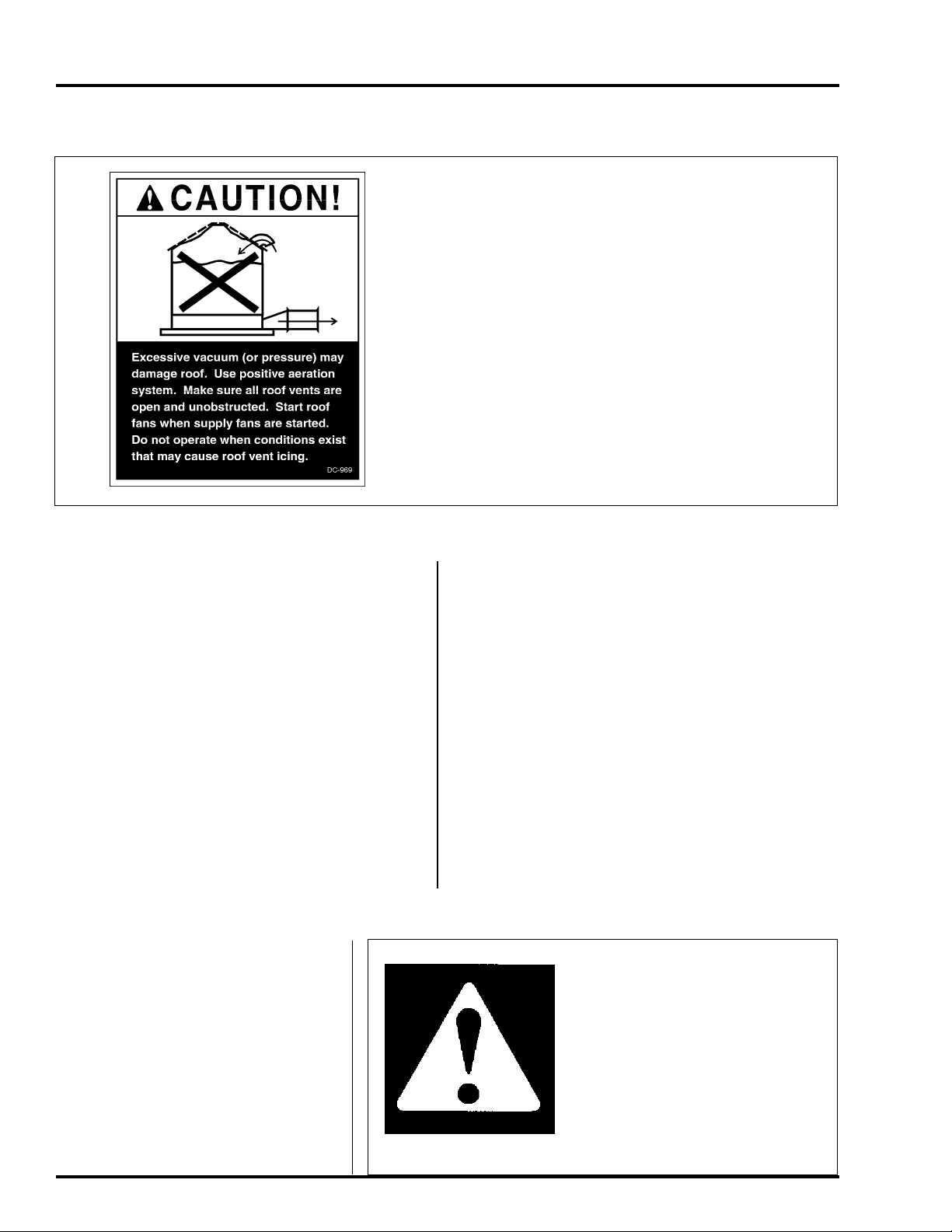
Roof Damage Warning and Disclaimer
GSI DOES NOT WARRANT ANY ROOF DAMAGE
CAUSED BY EXCESSIVE V ACUUM OR INTERNAL
PRESSURE FROM F ANS OR OTHER AIR MOVING
SYSTEMS. ADEQUATE VENTILATION AND/OR
"MAKEUP AIR" DEVICES SHOULD BE PROVIDED
FOR ALL POWERED AIR HANDLING SYSTEMS.
GSI DOES NOT RECOMMEND THE USE OF DOWNWARD FLOW SYSTEMS (SUCTION). SEVERE
ROOF DAMAGE CAN RESULT FROM ANY
BLOCKAGE OF AIR P ASSAGES. RUNNING FANS
DURING HIGH HUMIDITY/COLD WEA THER CONDITIONS CAN CAUSE AIR EXHAUST OR INT AKE
POR TS TO FREEZE.
Fan/Heater Installation & Operating Instructions
Thank you for choosing a T op Dry Series 2000 unit.
It is designed to give excellent performance and
service for many years.
This manual describes the wiring for all standard production Top Dry Series 2000 single fan,
multi-fan and 2000 Series Heater Control units. Different models are available for liquid propane or
natural gas fuel supply, with either single phase 230
volt, or three phase 208, 220, 380, 460 or 575 volt
electrical power.
The principal concern of the GSI Group, Inc.
("GSI") is your safety and the safety of others associated with grain handling equipment. This manual
is written to help you understand safe operating
procedures, and some of the problems that may be
en-countered by the operator or other personnel.
The symbol shown is used to call your
attention to instructions concerning your
personal safety. Watch for this symbol; it points out important safety precautions. It means "ATTENTION",
"WARNING", "CAUTION", and
"DANGER". Read the message and
be cautious to the possibility of personal injury or death.
As owner and/or operator, it is your responsibility to know what requirements, hazards and precautions exist, and to inform all personnel associated with the equipment, or who are in the fan area.
A void any alterations to the equipment. Such alterations may produce a very dangerous situation,
where serious injury or death may occur.
Safety Alert Symbol
WARNING! BE ALERT!
Personnel operating or working
around electric fans should read this
manual. This manual must be
delivered with the equipment to its
owner. Failure to read this manual
and its safety instructions is a misuse
of the equipment.
4
Page 5
1999 Top Dry Wiring Diagrams1999 Top Dry Wiring Diagrams
1999 Top Dry Wiring Diagrams
1999 Top Dry Wiring Diagrams1999 Top Dry Wiring Diagrams
Grain Systems, Inc. recommends contacting your local
power company , and having a representative survey your installation so the wiring is compatible
with their system, and adequate
power is supplied to your unit.
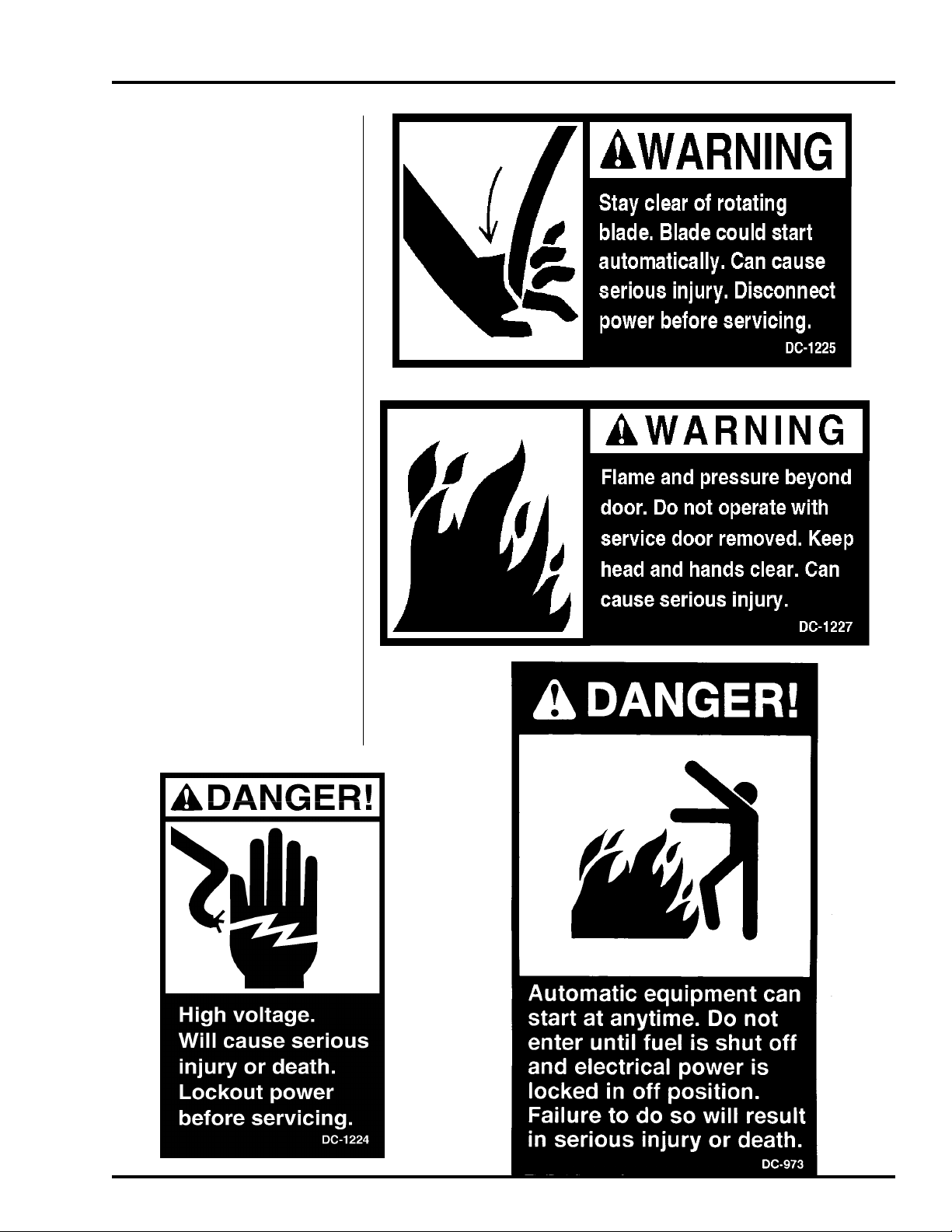
Safety decals should be read
and understood by all people in the
grain handling area. The rotating
blade, fire warning decals and
voltage danger decal must be displayed on the fan can. The bottom right decal should be present
on the inside bin door cover of the
two ring door, 24" porthole door
cover and the roof manway cover.
If a decal is damaged or is
missing contact:
Grain Systems, Inc.
1004 E. Illinois St.
Assumption, IL 62510
217-226-4421
A free replacement will be sent to
you.
SAFETYSAFETY
SAFETY
SAFETYSAFETY
5
Page 6

SAFETY PRECAUTIONSSAFETY PRECAUTIONS
SAFETY PRECAUTIONS
SAFETY PRECAUTIONSSAFETY PRECAUTIONS
1999 Top Dry Wiring Diagrams1999 Top Dry Wiring Diagrams
1999 Top Dry Wiring Diagrams
1999 Top Dry Wiring Diagrams1999 Top Dry Wiring Diagrams
READ THESE INSTRUCTIONS
BEFORE OPERA TION AND SERVICE
SAVE FOR FUTURE REFERENCE
1. Read and understand the operating manual before trying to operate the
dryer.
2. Power supply should be OFF for service of electrical components. Use
CAUTION in checking voltage or other procedures requiring power to
be ON.
3. Check for gas leaks at all gas pipe connections. If any leaks are detected, do not operate the dryer. Shut down and repair before further
operation.
4. Never attempt to operate the dryer by jumping or otherwise bypassing
any safety devices on the unit.
5. Set pressure regulator to avoid excessive gas pressure applied to burner
during ignition and when burner is in operation. Do not exceed maxi-
mum recommended drying temperature.
6. Keep the dryer clean. Do not allow fine material to accumulate in the
plenum or drying chamber.
Use Caution in the
Operation of this
Equipment
The design and manufacture of this
dryer is directed toward operator
safety. However, the very nature
of a grain dryer having a gas burner,
high voltage electrical equipment and
high speed rotating parts, does
present a hazard to personnel, which
can not be completely safeguarded
against, without interfering with efficient operation and reasonable access to components.
Use extreme caution in working
around high speed fans, gas-fired
heaters, augers and auxiliary conveyors, which may start without warning when the dryer is operating on
automatic control.
7. Use CAUTION in working around high speed fans, gas burners, augers
and auxiliary conveyors which START AUTOMATICALLY.
8. Do not operate in any area where combustible material will be drawn into
the fan.
9. Before attempting to remove and reinstall any propellor, make certain to
read the recommended procedure listed within the servicing section of
the manual.
10. Clean grain is easier to dry. Fine material increases resistance to airflow
and requires removal of extra moisture.
This product is intended for the use of grain handling only. Any other
use is considered a misuse of the product.
Some edges of the product components can be sharp. It is recommended that each component of this product be examined to determine if there are any safety considerations to be taken. Any and all
necessary personal protective equipment should be worn at all tines
when handling, assembling, installing and operation of the product
and/or components.
Guards are removed for illustration purpose only. All guardsmust be
in place before/during operation.
KEEP THE DRYER CLEAN
DO NOT ALLOW FINE
MATERIAL TO ACCUMULATE
IN THE PLENUM CHAMBER
OR SURROUNDING THE OUT-
SIDE OF THE DRYER
Continued safe, dependable operation of automatic equipment depends, to a great degree, upon the
owner. For a safe and dependable
drying system, follow the recommendations within this manual, and make
it a practice to regularly inspect the
operation of the unit for any developing problems or unsafe conditions.
Take special note of the safety precautions listed above before attempting to operate the dryer.
6
Page 7

SAFETY SIGN-OFF SHEETSAFETY SIGN-OFF SHEET
SAFETY SIGN-OFF SHEET
1999 Top Dry Wiring Diagrams1999 Top Dry Wiring Diagrams
1999 Top Dry Wiring Diagrams
1999 Top Dry Wiring Diagrams1999 Top Dry Wiring Diagrams
Date Employer’s Signature Employee
________________________________________________________________________________________________________________________________________________________________________________________________________________________________________________
________________________________________________________________________________________________________________________
________________________________________________________________________________________________________________________________________________________________________________________________________________________________________________
__________________________________________________________________________________________________________________________________________________________________________________________________________________________________________________
_________________________________________________________________________________________________________________________
__________________________________________________________________________________________________________________________________________________________________________________________________________________________________________________
________________________________________________________________________________________________________________________________________________________________________________________________________________________________
________________________________________________________________________________________________________________
________________________________________________________________________________________________________________________________________________________________________________________________________________________________
______________________________________________________________________________________________________________________________________________________________________________________________________________________________________________________
___________________________________________________________________________________________________________________________
______________________________________________________________________________________________________________________________________________________________________________________________________________________________________________________
________________________________________________________________________________________________________________________________________________________________________________________________________________________________________________
________________________________________________________________________________________________________________________
________________________________________________________________________________________________________________________________________________________________________________________________________________________________________________
__________________________________________________________________________________________________________________________________________________________________________________________________________________________________________________________
_____________________________________________________________________________________________________________________________
__________________________________________________________________________________________________________________________________________________________________________________________________________________________________________________________
____________________________________________________________________________________________________________________________________________________________________________________________________________________________________________________
__________________________________________________________________________________________________________________________
____________________________________________________________________________________________________________________________________________________________________________________________________________________________________________________
______________________________________________________________________________________________________________________________________________________________________________________________________________________________________________________________
_______________________________________________________________________________________________________________________________
______________________________________________________________________________________________________________________________________________________________________________________________________________________________________________________________
__________________________________________________________________________________________________________________________________________________________________________________________________________________________________________________________
_____________________________________________________________________________________________________________________________
__________________________________________________________________________________________________________________________________________________________________________________________________________________________________________________________
____________________________________________________________________________________________________________________________________________________________________________________________________________________________________________________________
______________________________________________________________________________________________________________________________
____________________________________________________________________________________________________________________________________________________________________________________________________________________________________________________________
SAFETY SIGN-OFF SHEETSAFETY SIGN-OFF SHEET
______________________________________________________________________________________________________________________________________________________________________________________________________________________________________________________
___________________________________________________________________________________________________________________________
______________________________________________________________________________________________________________________________________________________________________________________________________________________________________________________
____________________________________________________________________________________________________________________________________________________________________________________________________________________________________________
______________________________________________________________________________________________________________________
____________________________________________________________________________________________________________________________________________________________________________________________________________________________________________
__________________________________________________________________________________________________________________________________________________________________________________________________________________________________________________
_________________________________________________________________________________________________________________________
__________________________________________________________________________________________________________________________________________________________________________________________________________________________________________________
__________________________________________________________________________________________________________________________________________________________________________________________________________________________________________
_____________________________________________________________________________________________________________________
__________________________________________________________________________________________________________________________________________________________________________________________________________________________________________
____________________________________________________________________________________________________________________________________________________________________________________________________________________________________________
______________________________________________________________________________________________________________________
____________________________________________________________________________________________________________________________________________________________________________________________________________________________________________
__________________________________________________________________________________________________________________________________________________________________________________________________________________________________________________
_________________________________________________________________________________________________________________________
__________________________________________________________________________________________________________________________________________________________________________________________________________________________________________________
____________________________________________________________________________________________________________________________________________________________________________________________________________________________________________
______________________________________________________________________________________________________________________
____________________________________________________________________________________________________________________________________________________________________________________________________________________________________________
______________________________________________________________________________________________________________________________________________________________________________________________________________________________________________
_______________________________________________________________________________________________________________________
______________________________________________________________________________________________________________________________________________________________________________________________________________________________________________
____________________________________________________________________________________________________________________________________________________________________________________________________________________________________________
______________________________________________________________________________________________________________________
____________________________________________________________________________________________________________________________________________________________________________________________________________________________________________
____________________________________________________________________________________________________________________________________________________________________________________________________________________________________________
______________________________________________________________________________________________________________________
____________________________________________________________________________________________________________________________________________________________________________________________________________________________________________
__________________________________________________________________________________________________________________________________________________________________________________________________________________________________________
_____________________________________________________________________________________________________________________
__________________________________________________________________________________________________________________________________________________________________________________________________________________________________________
________________________________________________________________________________________________________________________________________________________________________________________________________________________________________________
________________________________________________________________________________________________________________________
________________________________________________________________________________________________________________________________________________________________________________________________________________________________________________
____________________________________________________________________________________________________________________________________________________________________________________________________________________________________________
______________________________________________________________________________________________________________________
____________________________________________________________________________________________________________________________________________________________________________________________________________________________________________
__________________________________________________________________________________________________________________________________________________________________________________________________________________________
_____________________________________________________________________________________________________________
__________________________________________________________________________________________________________________________________________________________________________________________________________________________
______________________________________________________________________________________________________________________________________________________________________________________________________________________________________________
_______________________________________________________________________________________________________________________
______________________________________________________________________________________________________________________________________________________________________________________________________________________________________________
__________________________________________________________________________________________________________________________________________________________________________________________________________________________________________
_____________________________________________________________________________________________________________________
__________________________________________________________________________________________________________________________________________________________________________________________________________________________________________
7
Page 8
ELECTRICAL POWER SUPPLYELECTRICAL POWER SUPPLY
ELECTRICAL POWER SUPPLY
ELECTRICAL POWER SUPPLYELECTRICAL POWER SUPPLY
Power Supply
An adequate power supply and proper wiring are important factors for maximum performance and long life of
the dryer. Electrical service must be adequate enough to
prevent low voltage damage to motors and control circuits (see Electrical Load Information).
Transformer and Wiring Voltage Drop
It is necessary to know the distance from the unit to the
available transformer, and the horsepower of your fan
unit. Advise the service representative of your local power
supplier that an additional load will be placed on the line.
Each fan motor should be wired through a fused or circuit breaker disconnect switch. Check on KVA rating of
transformers, considering total horsepower load. The
power supply wiring, main switch equipment and transformers must provide adequate motor starting and operating voltage. Voltage drop during motor starting should
not exceed 14% of normal voltage, and after motor is
running at full speed it should be within 8% of normal
voltage. Check Electrical Load Information for HP ratings and maximum amp loads to properly size wire and
fusing elements. Standard electrical safety practices and
codes should be used. (Refer to National Electrical Code
Standard Handbook by National Fire Protection Association).
1999 Top Dry Wiring Diagrams1999 Top Dry Wiring Diagrams
1999 Top Dry Wiring Diagrams
1999 Top Dry Wiring Diagrams1999 Top Dry Wiring Diagrams
and the ignition system. The ground rod must be in
accordance with local requirements.
Proper Installation of Ground Rod
It is not recommended that the rod be driven into dry
ground.
Follow these instructions for proper installation:
1. Dig a hole large enough to hold 1 to 2 gallons
of water.
2.Fill hole with water.
3.Insert rod through water and jab it into the ground.
4.Continue jabbing the rod up and down. The wa
ter will work its way down the hole, making
it possible to work the rod completely into
the ground. This method of installing the
rod gives a good conductive bond with the sur
rounding soil.
5.Connect the bare, copper ground wire to
the rod with the proper ground rod
clamp. See Figure 8.
6. Connect the bare copper ground wire to the fan
control boxes with a grounding lug.
7. Ground wire must
not have any breaks
or splices.
Machine to Earth Grounding
It is very important that a Machine To Ear th Ground
Rod be installed at the fan. This is true even if there is
a ground at the pole 15 feet away. Place the ground
rod that comes standard, within 8 feet of the dryer and
attach it to the dryer control panel with at least a #6
solid, bare, copper ground wire and the clamp provided. The grounding rod located at the power pole
will not provide adequate grounding for the dryer . The
proper grounding will provide additional safety in case
of any short and will ensure long life of all circuit boards,
8
Dig a hole large
enough to hold 1
or 2 gallons of
water . W ork the
ground rod into
the earth until it
is completely in
the ground.
Page 9

1999 Top Dry Wiring Diagrams1999 Top Dry Wiring Diagrams
1999 Top Dry Wiring Diagrams
1999 Top Dry Wiring Diagrams1999 Top Dry Wiring Diagrams
Series 2000 Master Fan/Heater Wiring
Domestic & CGA Models
9
Page 10
SERIES 2000 DOMESTIC & CGASERIES 2000 DOMESTIC & CGA
SERIES 2000 DOMESTIC & CGA
SERIES 2000 DOMESTIC & CGASERIES 2000 DOMESTIC & CGA
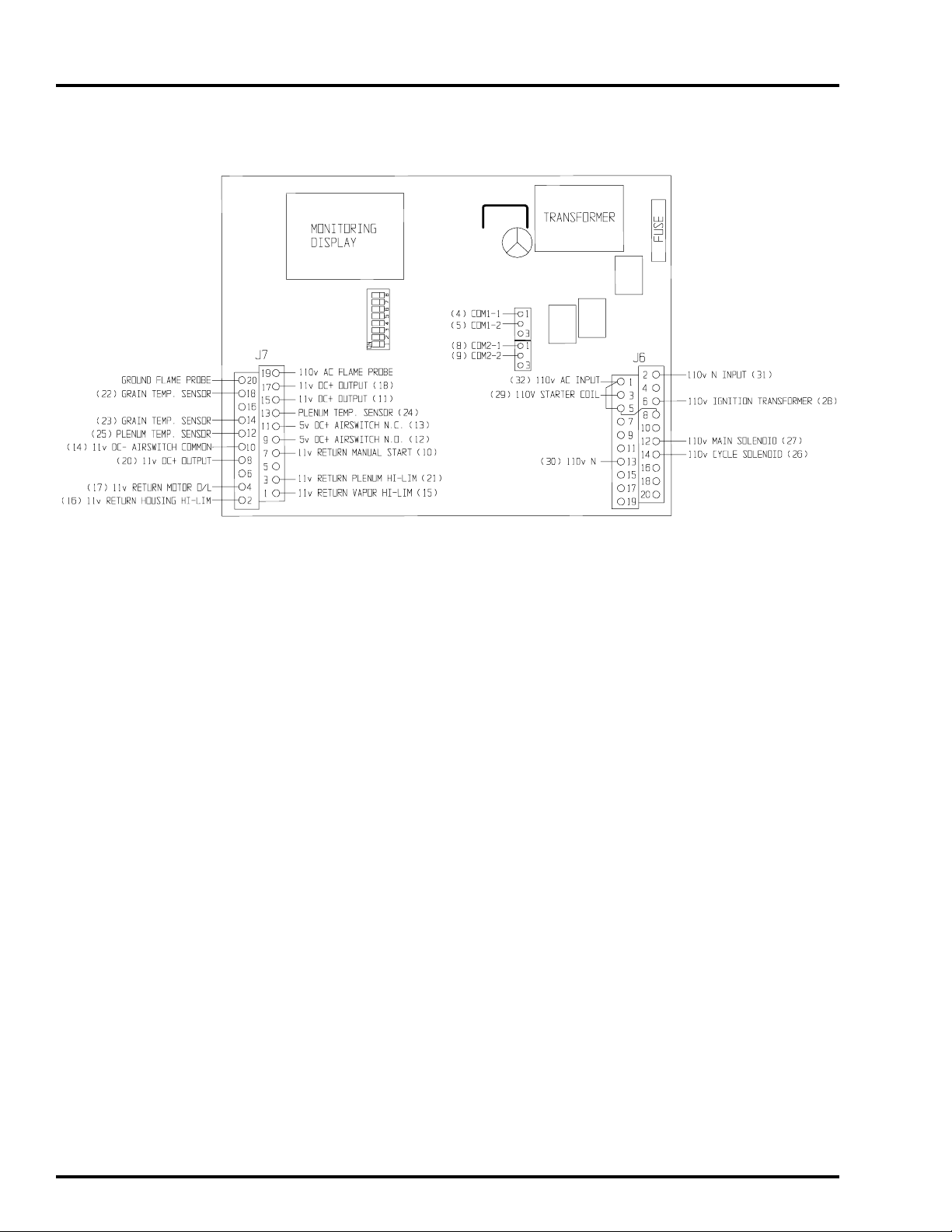
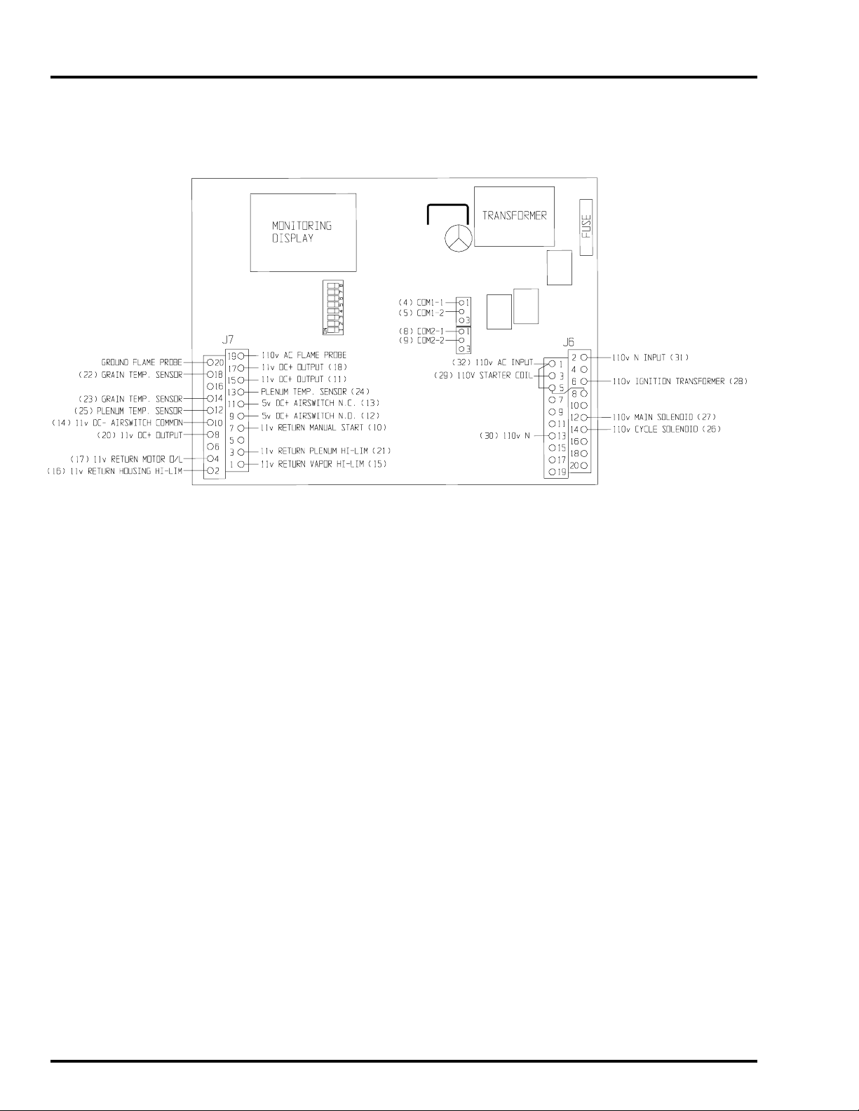
Series 2000 Master Heater Board Input/Output
1999 Top Dry Wiring Diagrams1999 Top Dry Wiring Diagrams
1999 Top Dry Wiring Diagrams
1999 Top Dry Wiring Diagrams1999 Top Dry Wiring Diagrams
10
Page 11
1999 Top Dry Wiring Diagrams1999 Top Dry Wiring Diagrams
1999 Top Dry Wiring Diagrams
1999 Top Dry Wiring Diagrams1999 Top Dry Wiring Diagrams
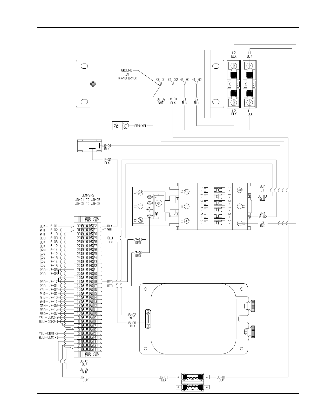
Series 2000 Master 220v1ph & 220v3ph Internal Wiring
SERIES 2000 DOMESTIC & CGASERIES 2000 DOMESTIC & CGA
SERIES 2000 DOMESTIC & CGA
SERIES 2000 DOMESTIC & CGASERIES 2000 DOMESTIC & CGA
11
Page 12
SERIES 2000 DOMESTIC & CGASERIES 2000 DOMESTIC & CGA
SERIES 2000 DOMESTIC & CGA
SERIES 2000 DOMESTIC & CGASERIES 2000 DOMESTIC & CGA
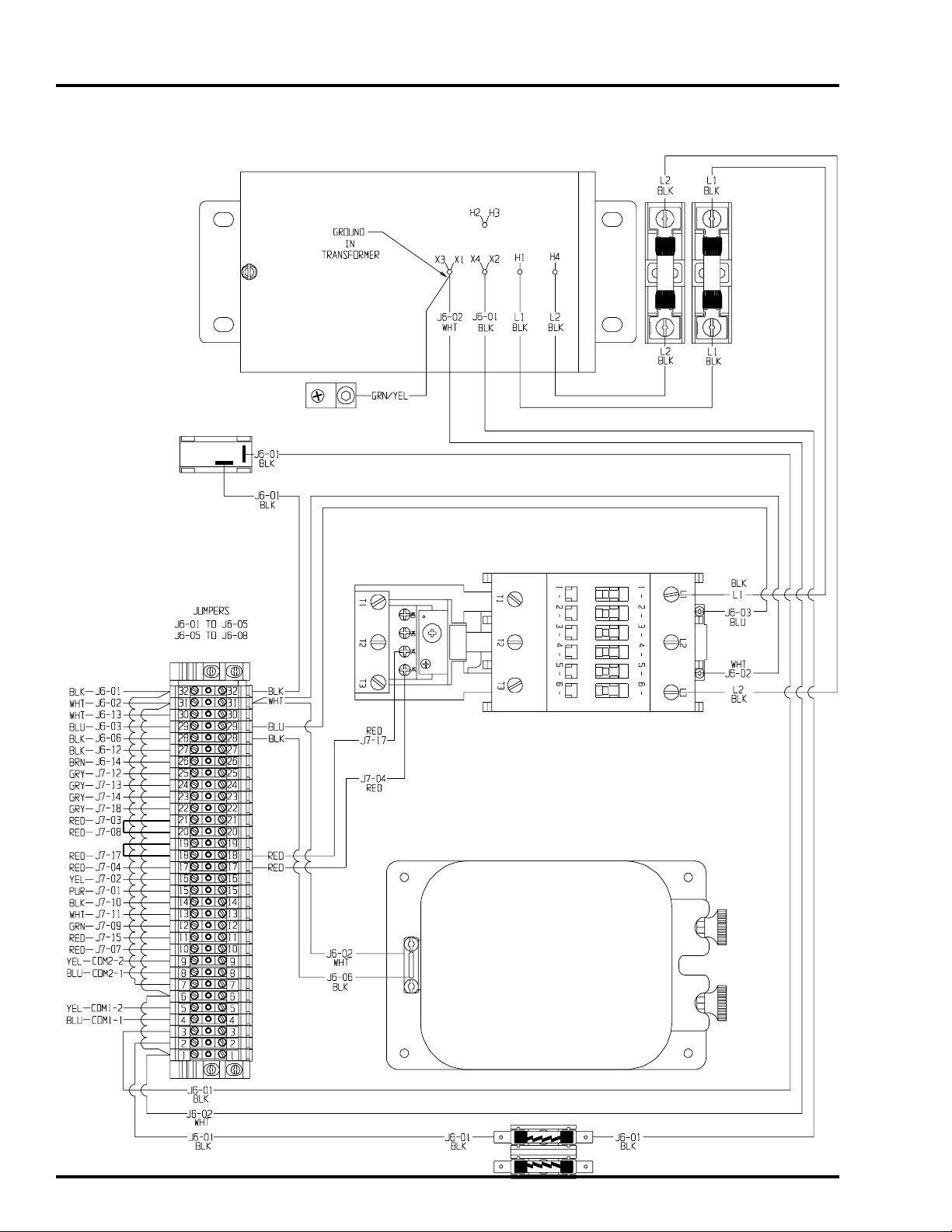
Series 2000 Master 460v3ph Internal Wiring
1999 Top Dry Wiring Diagrams1999 Top Dry Wiring Diagrams
1999 Top Dry Wiring Diagrams
1999 Top Dry Wiring Diagrams1999 Top Dry Wiring Diagrams
12
Page 13
1999 Top Dry Wiring Diagrams1999 Top Dry Wiring Diagrams
1999 Top Dry Wiring Diagrams
1999 Top Dry Wiring Diagrams1999 Top Dry Wiring Diagrams
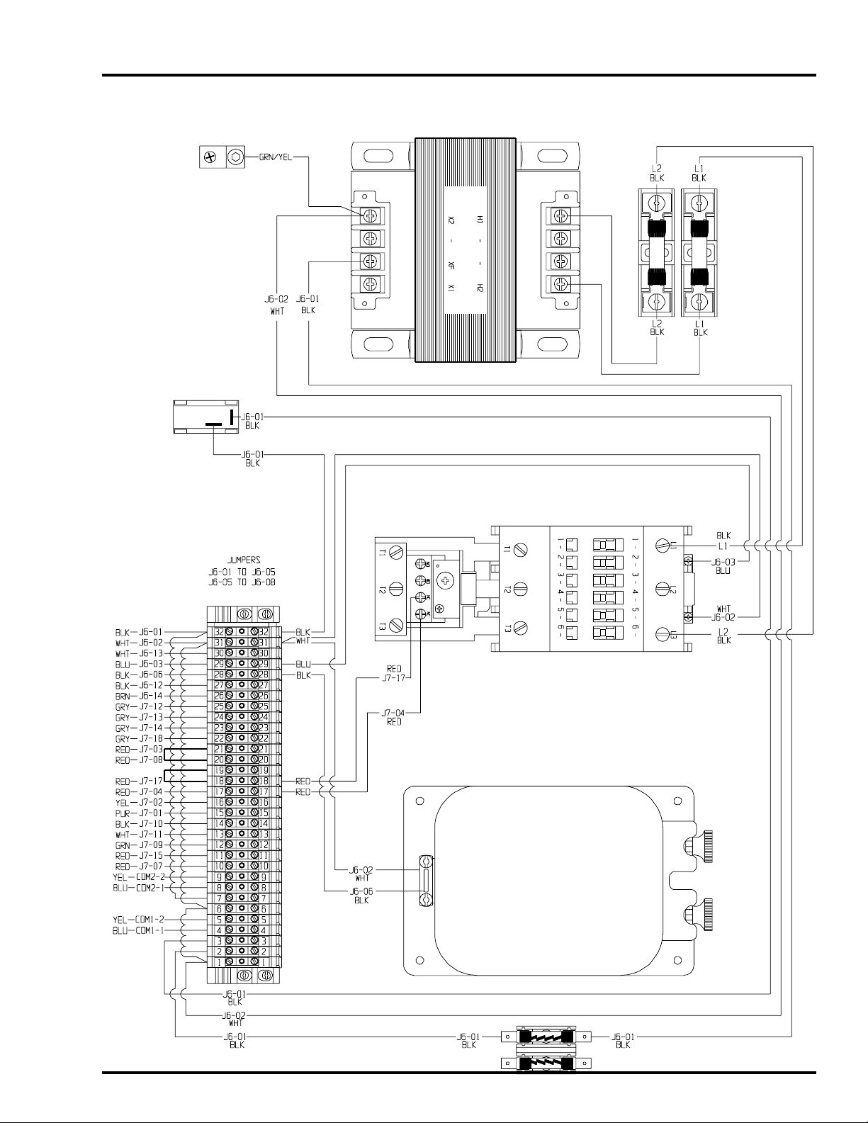
Series 2000 Master 575v3ph Internal Wiring
SERIES 2000 DOMESTIC & CGASERIES 2000 DOMESTIC & CGA
SERIES 2000 DOMESTIC & CGA
SERIES 2000 DOMESTIC & CGASERIES 2000 DOMESTIC & CGA
13
Page 14
SERIES 2000 DOMESTIC & CGASERIES 2000 DOMESTIC & CGA
SERIES 2000 DOMESTIC & CGA
SERIES 2000 DOMESTIC & CGASERIES 2000 DOMESTIC & CGA
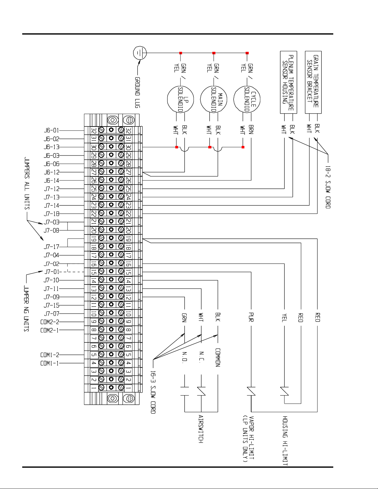
Series 2000 Master External Wiring
1999 Top Dry Wiring Diagrams1999 Top Dry Wiring Diagrams
1999 Top Dry Wiring Diagrams
1999 Top Dry Wiring Diagrams1999 Top Dry Wiring Diagrams
14
Page 15
1999 Top Dry Wiring Diagrams1999 Top Dry Wiring Diagrams
1999 Top Dry Wiring Diagrams
1999 Top Dry Wiring Diagrams1999 Top Dry Wiring Diagrams
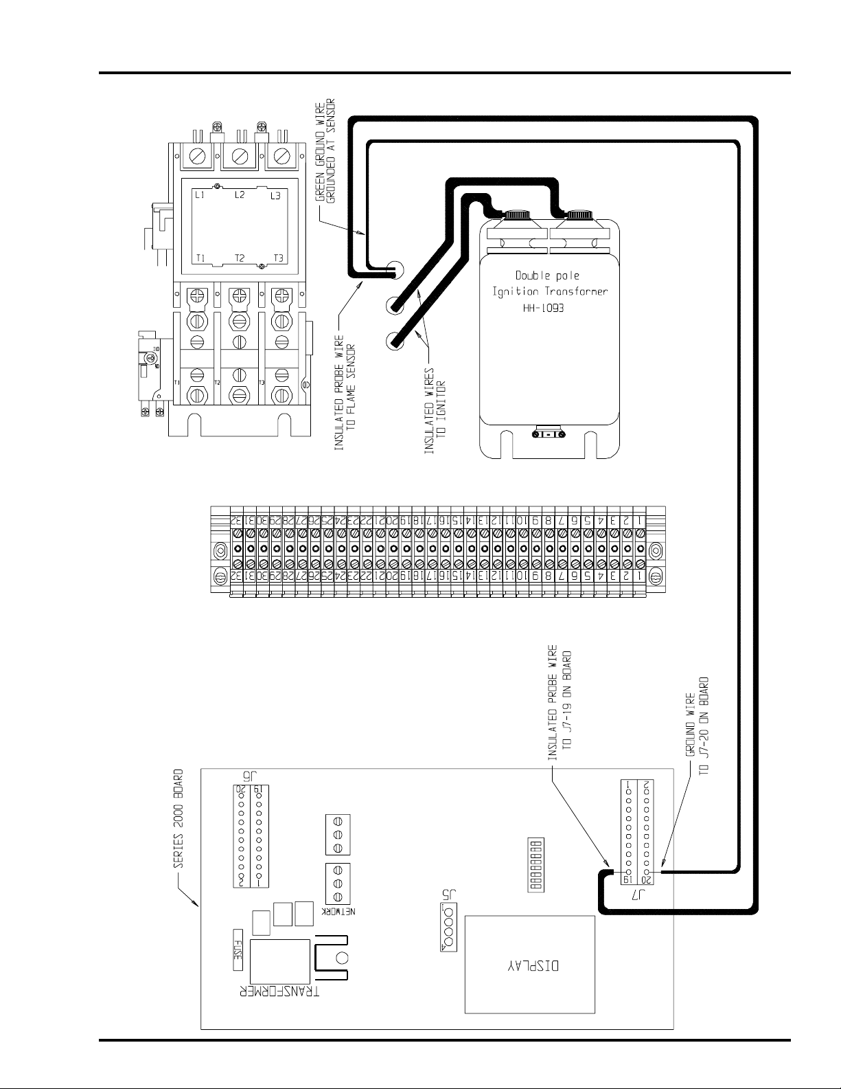
Series 2000 Master Ignitor/Probe Wiring
SERIES 2000 DOMESTIC & CGASERIES 2000 DOMESTIC & CGA
SERIES 2000 DOMESTIC & CGA
SERIES 2000 DOMESTIC & CGASERIES 2000 DOMESTIC & CGA
15
Page 16
SERIES 2000 DOMESTIC & CGASERIES 2000 DOMESTIC & CGA
SERIES 2000 DOMESTIC & CGA
SERIES 2000 DOMESTIC & CGASERIES 2000 DOMESTIC & CGA
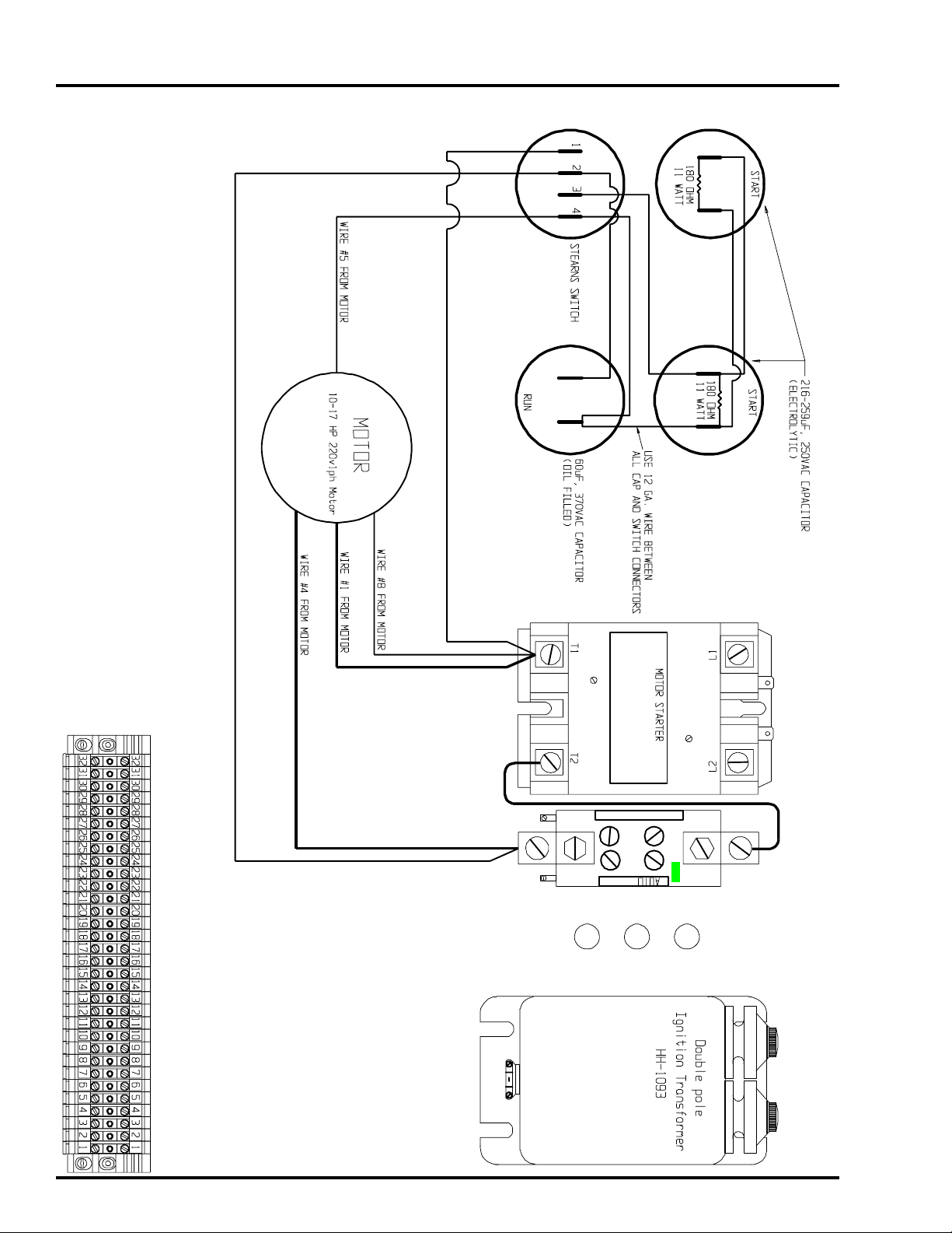
Series 2000 Master 15 Hp 220v1ph Capacitor Wiring
1999 Top Dry Wiring Diagrams1999 Top Dry Wiring Diagrams
1999 Top Dry Wiring Diagrams
1999 Top Dry Wiring Diagrams1999 Top Dry Wiring Diagrams
16
Page 17

1999 Top Dry Wiring Diagrams1999 Top Dry Wiring Diagrams
1999 Top Dry Wiring Diagrams
1999 Top Dry Wiring Diagrams1999 Top Dry Wiring Diagrams
Series 2000 Master Fan/Heater Wiring
European Models
17
Page 18
SERIES 2000 EUROPEANSERIES 2000 EUROPEAN
SERIES 2000 EUROPEAN
SERIES 2000 EUROPEANSERIES 2000 EUROPEAN
Series 2000 Master Heater Board Input/Output
1999 Top Dry Wiring Diagrams1999 Top Dry Wiring Diagrams
1999 Top Dry Wiring Diagrams
1999 Top Dry Wiring Diagrams1999 Top Dry Wiring Diagrams
18
Page 19

1999 Top Dry Wiring Diagrams1999 Top Dry Wiring Diagrams
1999 Top Dry Wiring Diagrams
1999 Top Dry Wiring Diagrams1999 Top Dry Wiring Diagrams
Series 2000 Master 380v3ph Internal Wiring - European Models
SERIES 2000 EUROPEANSERIES 2000 EUROPEAN
SERIES 2000 EUROPEAN
SERIES 2000 EUROPEANSERIES 2000 EUROPEAN
19
Page 20

SERIES 2000 EUROPEANSERIES 2000 EUROPEAN
SERIES 2000 EUROPEAN
SERIES 2000 EUROPEANSERIES 2000 EUROPEAN
Series 2000 Master 380v3ph External Wiring - European Models
1999 Top Dry Wiring Diagrams1999 Top Dry Wiring Diagrams
1999 Top Dry Wiring Diagrams
1999 Top Dry Wiring Diagrams1999 Top Dry Wiring Diagrams
20
Page 21

1999 Top Dry Wiring Diagrams1999 Top Dry Wiring Diagrams
1999 Top Dry Wiring Diagrams
1999 Top Dry Wiring Diagrams1999 Top Dry Wiring Diagrams
Series 2000 Master Ignitor/Probe Wiring.
SERIES 2000 EUROPEANSERIES 2000 EUROPEAN
SERIES 2000 EUROPEAN
SERIES 2000 EUROPEANSERIES 2000 EUROPEAN
21
Page 22

1999 Top Dry Wiring Diagrams1999 Top Dry Wiring Diagrams
1999 Top Dry Wiring Diagrams
1999 Top Dry Wiring Diagrams1999 Top Dry Wiring Diagrams
22
Page 23

1999 Top Dry Wiring Diagrams1999 Top Dry Wiring Diagrams
1999 Top Dry Wiring Diagrams
1999 Top Dry Wiring Diagrams1999 Top Dry Wiring Diagrams
Series 2000 Slave Fan/Heater Wiring
Domestic, CGA, and European Models
23
Page 24

SERIES 2000 SLAVE
Series 2000 Slave Heater Board Input/Output
1999 Top Dry Wiring Diagrams1999 Top Dry Wiring Diagrams
1999 Top Dry Wiring Diagrams
1999 Top Dry Wiring Diagrams1999 Top Dry Wiring Diagrams
24
Page 25

1999 Top Dry Wiring Diagrams1999 Top Dry Wiring Diagrams
1999 Top Dry Wiring Diagrams
1999 Top Dry Wiring Diagrams1999 Top Dry Wiring Diagrams
Series 2000 Slave Internal Wiring
SERIES 2000 SLAVE
25
Page 26

SERIES 2000 SLAVE
1999 Top Dry Wiring Diagrams1999 Top Dry Wiring Diagrams
1999 Top Dry Wiring Diagrams
1999 Top Dry Wiring Diagrams1999 Top Dry Wiring Diagrams
Series 2000 Slave External Wiring
26
Page 27

1999 Top Dry Wiring Diagrams1999 Top Dry Wiring Diagrams
1999 Top Dry Wiring Diagrams
1999 Top Dry Wiring Diagrams1999 Top Dry Wiring Diagrams
Series 2000 Slave Ignitor/Probe Wiring
SERIES 2000 SLAVE
27
Page 28

SERIES 2000 SLAVE
Series 2000 Slave 15 Hp 220v1ph Capacitor Wiring
1999 Top Dry Wiring Diagrams1999 Top Dry Wiring Diagrams
1999 Top Dry Wiring Diagrams
1999 Top Dry Wiring Diagrams1999 Top Dry Wiring Diagrams
28
Page 29

1999 Top Dry Wiring Diagrams1999 Top Dry Wiring Diagrams
1999 Top Dry Wiring Diagrams
1999 Top Dry Wiring Diagrams1999 Top Dry Wiring Diagrams
Series 2000 Batch
Control Box Wiring
29
Page 30

SERIES 2000 BATCH CONTROLS
Series 2000 Batch Remote Display Wiring - Domestic & CGA Units
1999 Top Dry Wiring Diagrams1999 Top Dry Wiring Diagrams
1999 Top Dry Wiring Diagrams
1999 Top Dry Wiring Diagrams1999 Top Dry Wiring Diagrams
30
Page 31

1999 Top Dry Wiring Diagrams1999 Top Dry Wiring Diagrams
1999 Top Dry Wiring Diagrams
1999 Top Dry Wiring Diagrams1999 Top Dry Wiring Diagrams
Series 2000 Batch Remote Display Wiring - European Units
SERIES 2000 BATCH CONTROLS
31
Page 32

SERIES 2000 BATCH CONTROLS
Series 2000 Batch Economy Control Wiring - Domestic & CGA Units
1999 Top Dry Wiring Diagrams1999 Top Dry Wiring Diagrams
1999 Top Dry Wiring Diagrams
1999 Top Dry Wiring Diagrams1999 Top Dry Wiring Diagrams
32
Page 33

1999 Top Dry Wiring Diagrams1999 Top Dry Wiring Diagrams
1999 Top Dry Wiring Diagrams
1999 Top Dry Wiring Diagrams1999 Top Dry Wiring Diagrams
Series 2000 Batch Economy Control Wiring - European Units
SERIES 2000 BATCH CONTROLS
33
Page 34

1999 Top Dry Wiring Diagrams1999 Top Dry Wiring Diagrams
1999 Top Dry Wiring Diagrams
1999 Top Dry Wiring Diagrams1999 Top Dry Wiring Diagrams
Series 2000 Autoflow Front Panel
34
Page 35

1999 Top Dry Wiring Diagrams1999 Top Dry Wiring Diagrams
1999 Top Dry Wiring Diagrams
1999 Top Dry Wiring Diagrams1999 Top Dry Wiring Diagrams
Series 2000 Autoflow
Control Box Wiring
35
Page 36

SERIES 2000 AUTOFLOW CONTROLS
Series 2000 Autoflow Input/Output Board Wiring
1999 Top Dry Wiring Diagrams1999 Top Dry Wiring Diagrams
1999 Top Dry Wiring Diagrams
1999 Top Dry Wiring Diagrams1999 Top Dry Wiring Diagrams
36
Page 37

1999 Top Dry Wiring Diagrams1999 Top Dry Wiring Diagrams
1999 Top Dry Wiring Diagrams
1999 Top Dry Wiring Diagrams1999 Top Dry Wiring Diagrams
Series 2000Autoflow Terminal Strip Wiring
SERIES 2000 AUTOFLOW CONTROLS
37
Page 38

SERIES 2000 AUTOFLOW CONTROLS
Series 2000 Autoflow Door Internal Wiring
1999 Top Dry Wiring Diagrams1999 Top Dry Wiring Diagrams
1999 Top Dry Wiring Diagrams
1999 Top Dry Wiring Diagrams1999 Top Dry Wiring Diagrams
38
Page 39

1999 Top Dry Wiring Diagrams1999 Top Dry Wiring Diagrams
1999 Top Dry Wiring Diagrams
1999 Top Dry Wiring Diagrams1999 Top Dry Wiring Diagrams
Series 2000Autoflow Door External Wiring
SERIES 2000 AUTOFLOW CONTROLS
39
Page 40

1999 Top Dry Wiring Diagrams1999 Top Dry Wiring Diagrams
1999 Top Dry Wiring Diagrams
1999 Top Dry Wiring Diagrams1999 Top Dry Wiring Diagrams
Series 2000 Autoflow Actuator
40
Page 41

1999 Top Dry Wiring Diagrams1999 Top Dry Wiring Diagrams
1999 Top Dry Wiring Diagrams
1999 Top Dry Wiring Diagrams1999 Top Dry Wiring Diagrams
Series 2000 Autoflow
Actuator Wiring
41
Page 42

SERIES 2000 AUTOFLOW ACTUATOR
Series 2000 Autoflow Actuator Schematic
1999 Top Dry Wiring Diagrams1999 Top Dry Wiring Diagrams
1999 Top Dry Wiring Diagrams
1999 Top Dry Wiring Diagrams1999 Top Dry Wiring Diagrams
42
Page 43

1999 Top Dry Wiring Diagrams1999 Top Dry Wiring Diagrams
1999 Top Dry Wiring Diagrams
1999 Top Dry Wiring Diagrams1999 Top Dry Wiring Diagrams
Series 2000 Autoflow Actuator Wiring
SERIES 2000 AUTOFLOW ACTUATOR
43
Page 44

1999 Top Dry Wiring Diagrams1999 Top Dry Wiring Diagrams
1999 Top Dry Wiring Diagrams
1999 Top Dry Wiring Diagrams1999 Top Dry Wiring Diagrams
Series 2000 Autoflow Fill System Control Box
44
Page 45

1999 Top Dry Wiring Diagrams1999 Top Dry Wiring Diagrams
1999 Top Dry Wiring Diagrams
1999 Top Dry Wiring Diagrams1999 Top Dry Wiring Diagrams
Series 2000 Autoflow
Fill System Control Box Wiring
45
Page 46

FILL SYSTEM CONTROL BOX
0 - Fill Systems, 1 - Aeration Fan Internal Wiring
1999 Top Dry Wiring Diagrams1999 Top Dry Wiring Diagrams
1999 Top Dry Wiring Diagrams
1999 Top Dry Wiring Diagrams1999 Top Dry Wiring Diagrams
46
Page 47

1999 Top Dry Wiring Diagrams1999 Top Dry Wiring Diagrams
1999 Top Dry Wiring Diagrams
1999 Top Dry Wiring Diagrams1999 Top Dry Wiring Diagrams
0 - Fill Systems, 1 - Aeration Fan Door Wiring
FILL SYSTEM CONTROL BOX
47
Page 48

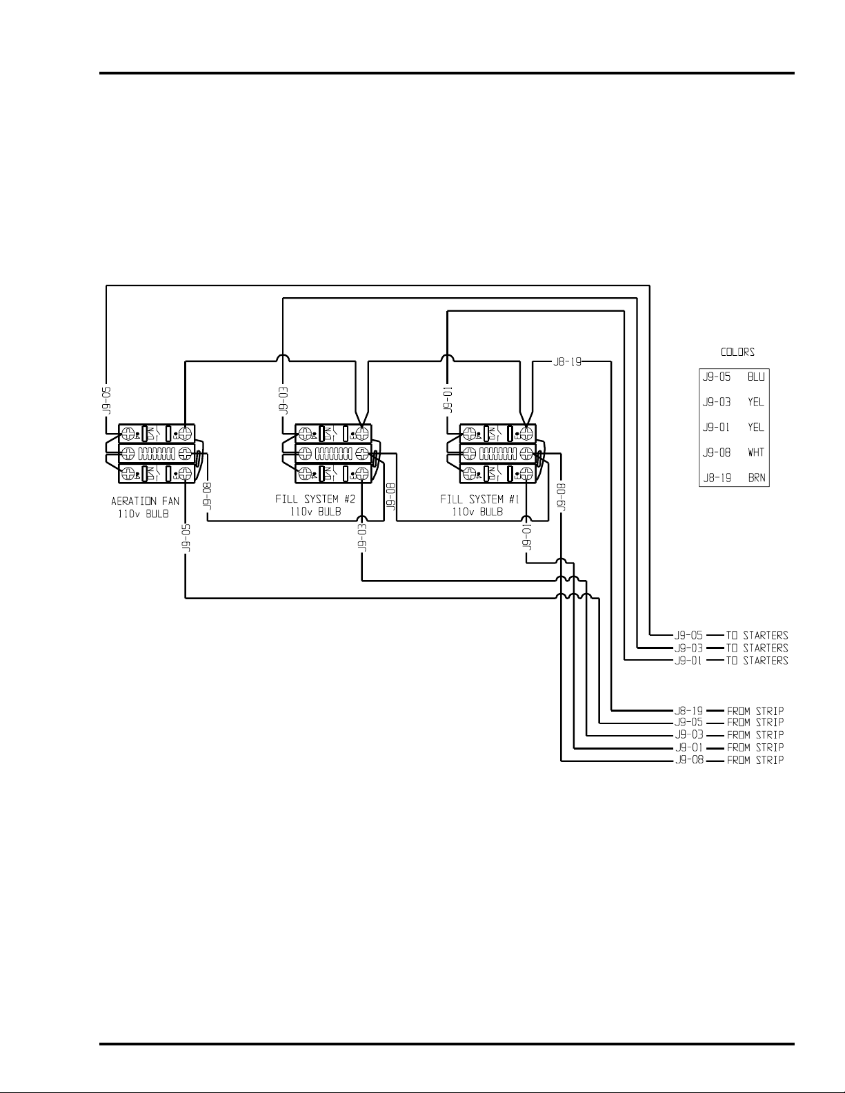
FILL SYSTEM CONTROL BOX
1 - Fill Systems, 0 - Aeration Fan Internal Wiring
1999 Top Dry Wiring Diagrams1999 Top Dry Wiring Diagrams
1999 Top Dry Wiring Diagrams
1999 Top Dry Wiring Diagrams1999 Top Dry Wiring Diagrams
48
Page 49

1999 Top Dry Wiring Diagrams1999 Top Dry Wiring Diagrams
1999 Top Dry Wiring Diagrams
1999 Top Dry Wiring Diagrams1999 Top Dry Wiring Diagrams
1 - Fill Systems, 0 - Aeration Fan Door Wiring
FILL SYSTEM CONTROL BOX
49
Page 50

FILL SYSTEM CONTROL BOX
1 - Fill Systems, 1 - Aeration Fan Internal Wiring
1999 Top Dry Wiring Diagrams1999 Top Dry Wiring Diagrams
1999 Top Dry Wiring Diagrams
1999 Top Dry Wiring Diagrams1999 Top Dry Wiring Diagrams
50
Page 51

1999 Top Dry Wiring Diagrams1999 Top Dry Wiring Diagrams
1999 Top Dry Wiring Diagrams
1999 Top Dry Wiring Diagrams1999 Top Dry Wiring Diagrams
1 - Fill Systems, 1 - Aeration Fan Door Wiring
FILL SYSTEM CONTROL BOX
51
Page 52

FILL SYSTEM CONTROL BOX
2 - Fill Systems, 0 - Aeration Fan Internal Wiring
1999 Top Dry Wiring Diagrams1999 Top Dry Wiring Diagrams
1999 Top Dry Wiring Diagrams
1999 Top Dry Wiring Diagrams1999 Top Dry Wiring Diagrams
52
Page 53

1999 Top Dry Wiring Diagrams1999 Top Dry Wiring Diagrams
1999 Top Dry Wiring Diagrams
1999 Top Dry Wiring Diagrams1999 Top Dry Wiring Diagrams
2 - Fill Systems, 0 - Aeration Fan Door Wiring
FILL SYSTEM CONTROL BOX
53
Page 54

FILL SYSTEM CONTROL BOX
2 - Fill Systems, 1 - Aeration Fan Internal Wiring
1999 Top Dry Wiring Diagrams1999 Top Dry Wiring Diagrams
1999 Top Dry Wiring Diagrams
1999 Top Dry Wiring Diagrams1999 Top Dry Wiring Diagrams
54
Page 55
1999 Top Dry Wiring Diagrams1999 Top Dry Wiring Diagrams
1999 Top Dry Wiring Diagrams
1999 Top Dry Wiring Diagrams1999 Top Dry Wiring Diagrams
2 - Fill Systems, 1 - Aeration Fan Door Wiring
FILL SYSTEM CONTROL BOX
55
Page 56

1999 Top Dry Wiring Diagrams1999 Top Dry Wiring Diagrams
1999 Top Dry Wiring Diagrams
1999 Top Dry Wiring Diagrams1999 Top Dry Wiring Diagrams
56
Page 57

1999 Top Dry Wiring Diagrams1999 Top Dry Wiring Diagrams
1999 Top Dry Wiring Diagrams
1999 Top Dry Wiring Diagrams1999 Top Dry Wiring Diagrams
WARRANTYWARRANTY
WARRANTY
WARRANTYWARRANTY
THE GSI GROUP , INC. ("GSI") WARRANTS ALL PRODUCTS MANUF ACTURED BY GSI TO
BE FREE OF DEFECTS IN MATERIAL AND WORKMANSHIP UNDER NORMAL USAGE
AND CONDITIONS FOR A PERIOD OF TWEL VE MONTHS AFTER RET AIL SALE T O THE
ORIGINAL END USER OF SUCH PRODUCTS. GSI'S ONLY OBLIGATION IS, AND
PURCHASER'S SOLE REMEDY SHALL BE FOR GSI, TO REPAIR OR REPLACE, AT GSI'S
OPTION AND EXPENSE, PRODUCTS THA T , IN GSI'S SOLE JUDGMENT , CONTAIN A MATERIAL DEFECT DUE TO MATERIALS OR WORKMANSHIP . ALL DELIVER Y AND SHIPMENT CHARGES TO AND FROM GSI'S FACTORY WILL BE PURCHASER'S RESPONSIBILITY . EXPENSES INCURRED BY OR ON BEHALF OF THE PURCHASER WITHOUT PRIOR
WRITTEN AUTHORIZA TION FROM AN AUTHORIZED EMPLOYEE OF GSI SHALL BE THE
SOLE RESPONSIBILITY OF THE PURCHASER.
EXCEPT FOR THE ABOVE STATED EXPRESS LIMITED WARRANTIES, GSI MAKES NO WARRANTY
OF ANY KIND, EXPRESSED OR IMPLIED, INCLUDING, WITHOUT LIMITATION, WARRANTIES OF
MERCHANTABILITY OR FITNESS FOR A PARTICULAR PURPOSE OR USE IN CONNECTION WITH
(i) PRODUCT MANUFACTURED OR SOLD BY GSI OR (ii) ANY ADVICE, INSTRUCTION, RECOMMENDATION OR SUGGESTION PROVIDED BY AN AGENT, REPRESENTATIVE OR EMPLOYEE OF GSI
REGARDING OR RELATED TO THE CONFIGURATION, INSTALLATION, LAYOUT, SUITABILITY FOR
A PARTICULAR PURPOSE, OR DESIGN OF SUCH PRODUCT OR PRODUCTS.
IN NO EVENT SHALL GSI BE LIABLE FOR ANY DIRECT, INDIRECT, INCIDENTAL OR CONSEQUENTIAL DAMAGES, INCLUDING, WITHOUT LIMITATION, LOSS OF ANTICIPATED PROFITS OR
BENEFITS. PURCHASER'S SOLE AND EXCLUSIVE REMEDY SHALL BE LIMITED TO THAT STATED
ABOVE, WHICH SHALL NOT EXCEED THE AMOUNT PAID FOR THE PRODUCT PURCHASED. THIS
WARRANTY IS NOT TRANSFERABLE AND APPLIES ONLY TO THE ORIGINAL PURCHASER. GSI
SHALL HAVE NO OBLIGATION OR RESPONSIBILITY FOR ANY REPRESENTATIVE OR WARRANTIES MADE BY OR ON BEHALF OF ANY DEALER, AGENT OR DISTRIBUTOR OF GSI.
GSI ASSUMES NO RESPONSIBILITY FOR FIELD MODIFICA TIONS OR ERECTION DEFECTS WHICH
CREATE STRUCTURAL OR STORAGE QUALITY PROBLEMS. MODIFICATIONS TO THE PRODUCT
NOT SPECIFICALLY COVERED BY THE CONTENTS OF THIS MANUAL WILL NULLIFY ANY PRODUCT WARRANTY THAT MIGHT HAVE BEEN OTHERWISE AVAILABLE.
THE FOREGOING WARRANTY SHALL NOT COVER PRODUCTS OR PARTS WHICH HAVE BEEN
DAMAGED BY NEGLIGENT USE, MISUSE, ALTERATION OR ACCIDENT. THIS WARRANTY COVERS ONLY PRODUCTS MANUFACTURED BY GSI. THIS WARRANTY IS EXCLUSIVE AND IN LIEU
OF ALL OTHER WARRANTIES EXPRESS OR IMPLIED. GSI RESERVES THE RIGHT TO MAKE DESIGN OR SPECIFICATION CHANGES AT ANY TIME.
PRIOR TO INSTALLATION, PURCHASER HAS THE REPONSIBILITY TO RESEARCH AND COMPLY WITH ALL FEDERAL, STATE AND LOCAL CODES WHICH MAY APPLY TO THE LOCATION
AND INSTALLATION
57
Page 58

1999 Top Dry Wiring Diagrams1999 Top Dry Wiring Diagrams
1999 Top Dry Wiring Diagrams
1999 Top Dry Wiring Diagrams1999 Top Dry Wiring Diagrams
58
1004 E. Illinois
St.
Assumption, IL
62510
Phone 217-226-
4421
Fax 217-226-4498
July 1999
 Loading...