

Page 1
Instructions
1004 East Illinois Street • Assumption, IL 62510 • 217-226-4421
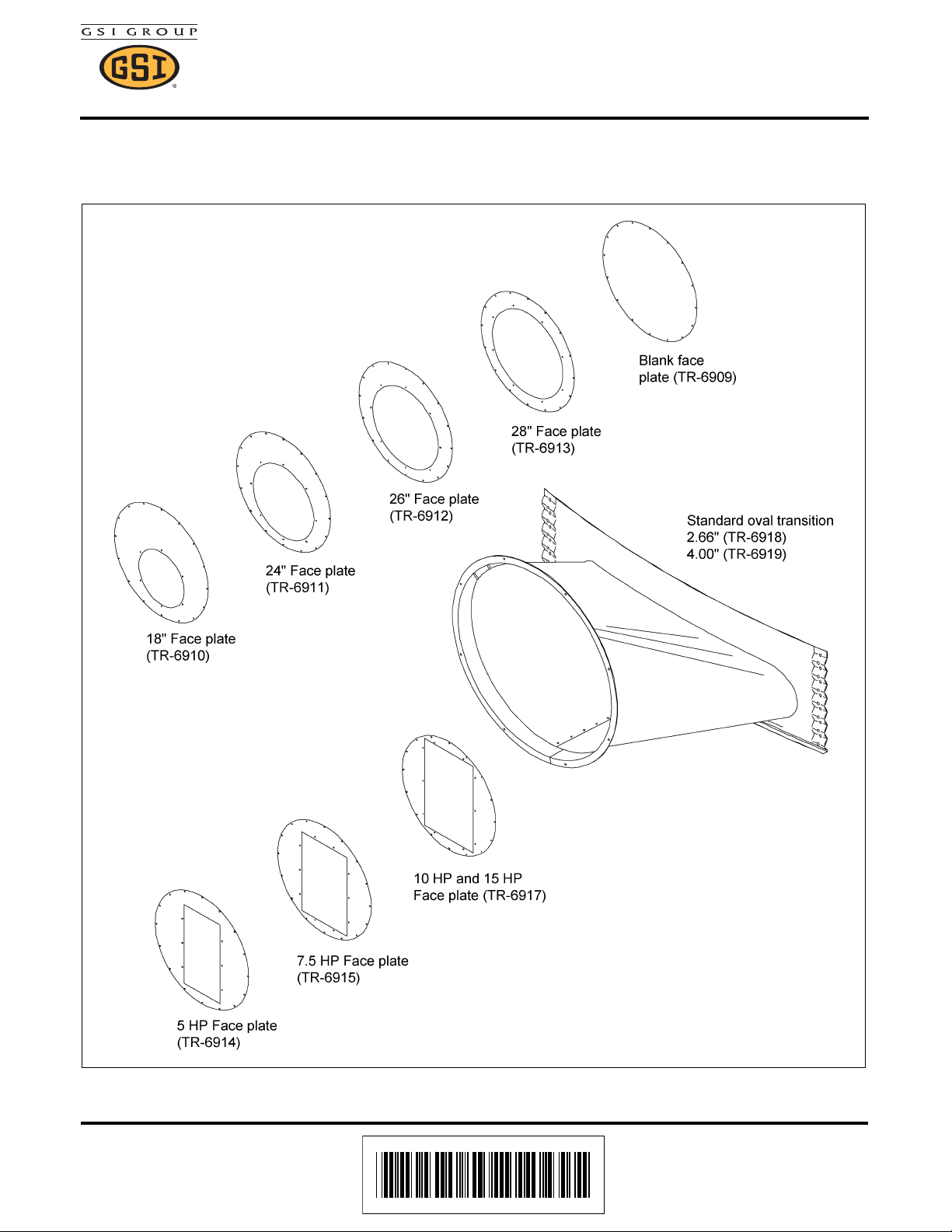
This transition is designed to attach to a 55-1/4" x 12-1/4" air entrance opening in the grain bin sidewall
below the perforated floor. The transition is fabricated from galvanized material and will be shipped
“knocked down” for field assembly. Ample caulking is provided for complete weatherproof construction.
Standard Oval Transition Assembly
Figure 1 Transition Face Plate Assembly
Date: 07-11-08 PNEG-838
Printed in the U.S.A.
Copyright © 2008 by GSI Group
www.gsiag.com
PNEG-838
Page 1 of 4
Page 2
Standard Oval Transition Assembly
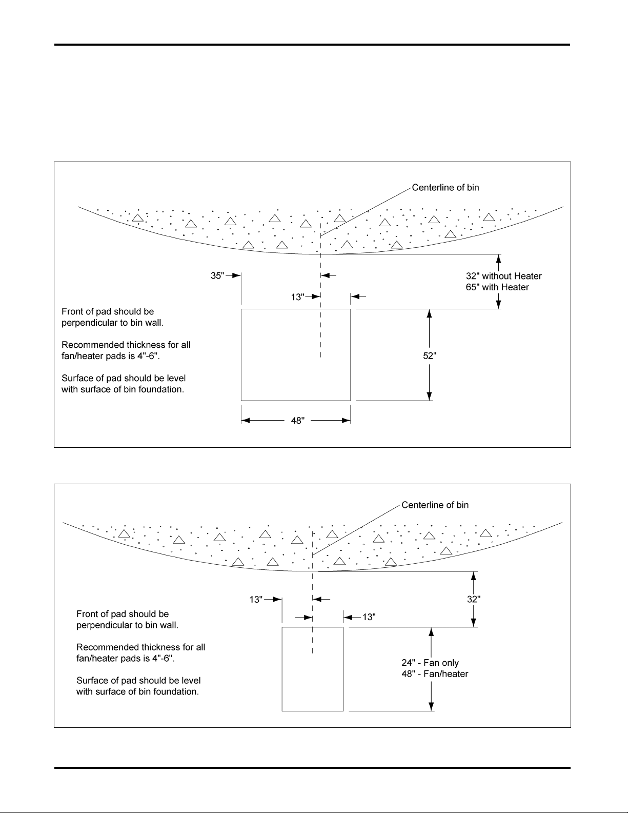
Pad Location
IMPORTANT: Fan pad/fan must be level for proper operation. Vibration problems can result from
improper fan leveling.
NOTE: Please note new fan pad location. All fan pads should start 32" from bin wall. If heater is to be
used or possibly used in the future, it is recommended that a full fan/heater pad is poured.
Figure 2 Centrifugal Pad Location
Figure 3 Vane Axial Pad Locati on
Page 2 of 4 PNEG-838
Page 3

Standard Oval Transition Assembly
Transition Instructions
1. Fold and lap opposite ends of housing wrapper. Using 1/4"-20 x 1/2" bolts, bolt the seams together
leaving the end two (2) holes open.
2. Rotate housing wrapper until bolted seam is on bottom. Slip housing through entrance collar until
front edge is flush with extruded lip.
Figure 4
3. Align holes designated “A” and bolt them first. Place center brace into position and bolt top and
bottom. Complete by bolting remaining holes and inserting remaining braces as shown in Figure 5.
Figure 5
4. Slide transition face collar into opening, with crimped surface at top. Secure with remaining bolts.
Figure 6
PNEG-838 Page 3 of 4
Page 4

Standard Oval Transition Assembly
Transition Instructions (Continued)
5. Cut 55-1/4" x 12-1/4" hole through base sheet as shown in Figure 7. Use stiffener angle
as a template and field drill three (3) 3/8" diameter holes per stiffener angle as shown in Figure 7.
Use 5/16" x 3/4" bin bolts to attach stiffener angles to sidewall.
6. Apply a generous bead of caulk around perimeter of opening. Using self-drilling screws attach
transition housing assembly as shown in Figure 7.
Figure 7
Page 4 of 4 PNEG-838
 Loading...