

Page 1
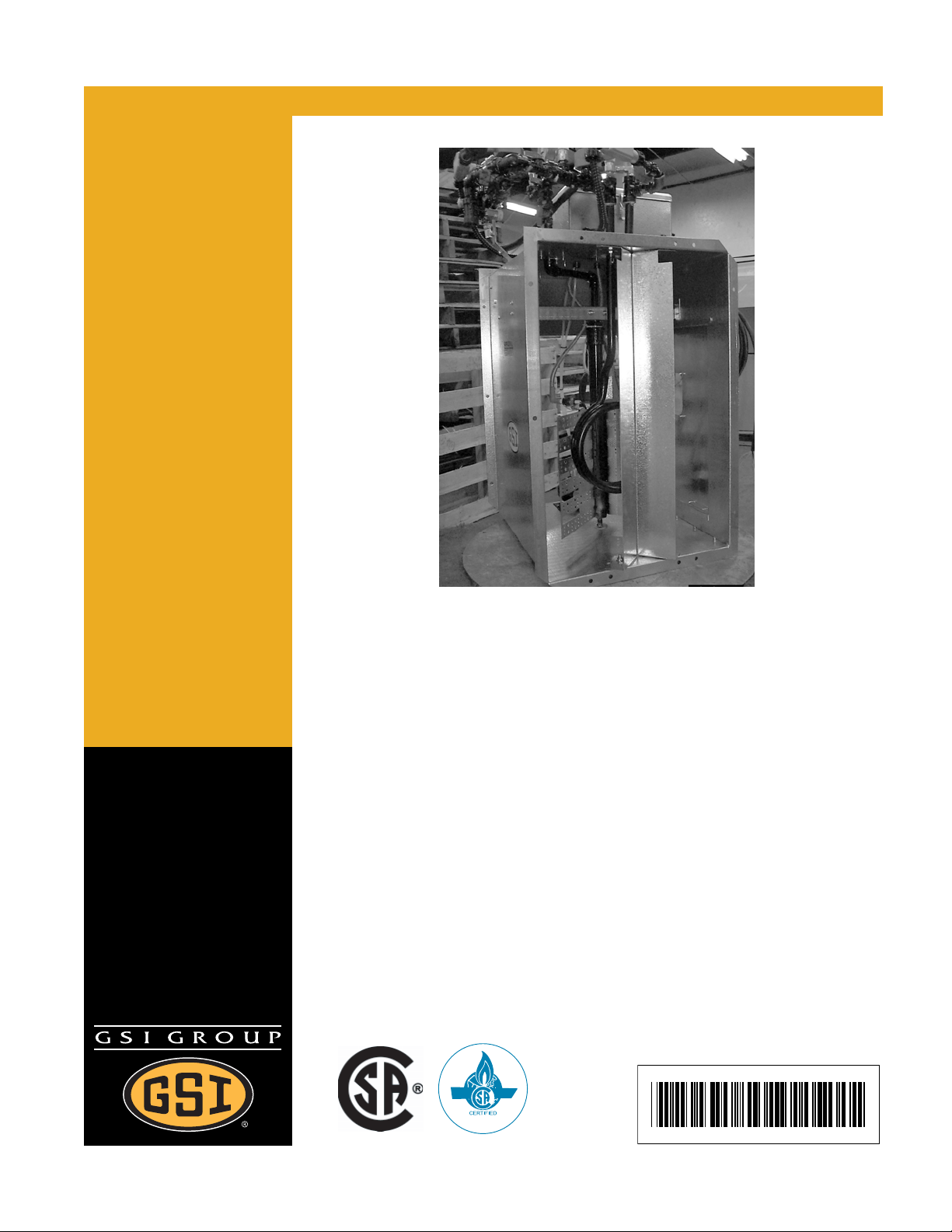
Deluxe Downwind Centrifugal
Heater Installation and
Operating Instructions
Model # CH_-_ _-_ _-D (HIGH)
Model # CL_-_ _-_ _-D (LOW)
Owner ’s Manual
PNEG-823
Date: 07-18-08
PNEG-823
Page 2

Check List
1. All wire connections
2. Spark plug gap 0.125
3. Pipe train tightness and gas leaks
4. Flame sensor tight
5. Fuse in place, extra fuse provided
6. Time delay reset
7. Indicator light
8. Pressure gauge
9. Regulator adjusted
10. Shut off valve operates correctly
11. Vapor High-Limit
12. Unit cycles ON to OFF
13. Heat rise even across transition
14. Unit cycles High-Low (High-Low only)
15. Modulating valve holds temperature within 1 degree (modulating units only)
16. All decals and serial number tag
17. Aesthetic appearance
18. Manual
Tester Signature:
Date:______________________________
______________________________
This equipment shall be installed in accordance with the current installation codes for gas burning
appliances and equipment, CAN1-B149.1 and B149.2, or applicable provincial regulations which
should be carefully followed in all cases. Authorities having jurisdiction should be consulted before
installations are made.
2 PNEG-823 Deluxe Downwind Heater
Page 3

Table of Contents
Contents
Chapter 1 Safety ..................................................................................................................................................5
Safety Guidelines ............................................................................................................................... 5
Fuel Warning ...................................................................................................................................... 6
Power Warning ................................................................................................................................... 6
Proper Use of Product ........................................................................................................................ 6
Heater Operation ................................................................................................................................ 6
Safety Instructions .............................................................................................................................. 7
Chapter 2 Decals .................................................................................................................................................9
Chapter 3 Heater Installation ...........................................................................................................................10
Machine to Earth Ground ............................. .... ... ... ... .... ... ... ... .... ... ... ... ... .......................................... 10
Proper Installation of the Ground Rod .............................................................................................. 10
Previously Installed Units ................................................................................................................. 11
Fuel Connection ............................................................................................................................... 12
Chapter 4 Installation ........................................................................................................................................13
Heater Specifications .................................................................................................................... ... 13
Plenum Thermostat Mounting ................................ ... .... ... ... ... .... ... ... ... ... .... ... ... ... .... ... ... ... ................ 13
Transition High-Limit Installation ...................................................................................................... 14
Chapter 5 Bin Configuration ............................................................................................................................15
Operating Temperature Table ................... ... .... ... ... ... .... ... ... ... .......................................................... 15
Chapter 6 Second Heater Installation ............................................................................................................. 16
For Units Using HF-7318 Control Board .......................................................................................... 16
Installation for Standard Units .......................................................................................................... 16
Additional Steps for High-Low Units ....................................... .... ... ... ... ... .... ... ... ................................ 16
Electrical Installation (230V Fans) .................................................................................................... 17
Electrical Installation (460V Fans) .................................................................................................... 18
Chapter 7 Wiring Diagram ................................................................................................................................19
Chapter 8 Operating Procedure .......................................................................................................................20
Cycling Heater Operation ................................................................................................................. 20
High-Low Heater Operation ................. ... ... ... .... ... ... ... .... ................................................................ ... 20
Modulating Valve Operation ................ ... .......................................................... ... .... ... ... ... ... .... ... ...... 21
10 HP-15 HP Units BTUs per Gauge Pressure (PSI) Propane Models (Approximate) .................... 22
10 HP-15 HP Units BTUs per Gauge Pressure (PSI) Natural Gas Models (Approximate) .............. 22
20 HP-40 HP Units BTUs per Gauge Pressure (PSI) Propane Models (Approximate) .................... 23
20 HP-40 HP Units BTUs per Gauge Pressure (PSI) Natural Gas Models (Approximate) .............. 24
Low-Temperature Units BTUs per Gauge Pressure (PSI) Propane Models (Approximate) ............ 24
Low-Temperature Units BTUs per Gauge Pressure (PSI) Natural Gas Models (Approximate) ...... 24
Adjusting the Vaporizer .................................................................................................................... 25
PNEG-823 Deluxe Downwind Heater 3
Page 4

Table of Contents
Chapter 9 Parts List ..........................................................................................................................................26
DW Propane Vapor High-Fire Pipetrain Components ...................................................................... 27
DW Propane Vapor High-Low Fire Pipetrain Components .............................................................. 28
DW Propane Vapor Modulating Pipetrain Components ................................................................... 29
DW NG High-Fire Pipetrain Components ......................................................................................... 30
DW NG High-Low Fire Pipetrain Components ................................................................................. 31
DW NG Modulating Pipetrain Components .............................. ........................................................ 32
DW LP High-Fire Pipetrain Components .......................................................................................... 33
DW LP High-Low Pipetrain Components ......................................................................................... 34
DW LP Modulating Pipetrain Components ....................................................................................... 35
40 HP DW High-Temperature Heater Parts ..................................................................................... 36
40 HP DW Low-Temperature Heater Parts ...................................................................................... 37
DW Gas Heater Control Box Parts ................................................................................................... 38
DW Propane Vapor Pipetrain Parts .................................................................................................. 39
DW Propane Vapor High-Low Pipetrain Parts .................................................................................. 40
Chapter 10 Warranty .........................................................................................................................................41
4 PNEG-823 Deluxe Downwin d H e at er
Page 5
1. Safety
Safety Guidelines
This manual contains information that is important for you, the owner/operator, to know and understand.
This information relates to protecting personal safety and preventing equipment problems. It is the
responsibility of the owner/operator to inform anyone operating or working in the area of this equipment
of these safety guidelines. To help you recognize this information, we use the symbols that are defined
below. Please read the manual and pay attention to these sections. Failure to read this manual and its
safety instructions is a misuse of the equipment and may lead to serious injury or death.
This is the safety alert symbol. It is used to alert you to
potential personal injury hazards. Obey all safety
messages that follow this symbol to avoid possible
injury or death.
DANGER indicates an imminently hazardous situation
which, if not avoided, will result in death or serious injury.
WARNING indicates a potentially hazardous situation
which, if not avoided, could result in death or serious injury.
CAUTION indicates a potentially hazardous situation which,
if not avoided, may result in minor or moderate injury.
CAUTION used without the safety alert symbol indicates a
potentially hazardous situation which, if not avoided, may
result in property damage.
NOTE indicates information about the equipment that you
should pay special attention.
DANGER! BE ALERT!
Personnel operating or working around electrical equipment should read this manual.
This manual must be delivered with the equipment to its owner. Failure to read this
manual and its safety instructions is a misuse of the equipment.
PNEG-823 Deluxe Downwind Heater 5
Page 6
1. Safety
Fuel Warning
Do not use propane tanks which have previously been used for ammonia unless
they have been purged according to procedures of the National LP Association.
Be sure fuel supply system complies with all local codes for LP gas installations.
DO NOT USE FLAME FOR LEAK TESTING.
Power Warning
Be sure power is disconnected and locked out before installation. Failure to do so may cause serious
injury or death.
IMPORTANT: Heater must be interlocked with fan for safe operation.
IMPORTANT: Thermostat must be installed for safe operation.
Proper Use of Product
This product is intended for the use of grain drying onl y. Any other use is a misuse of this product. This
product has sharp edges. These sharp edges may cause serious injury. To avoid injury handle sharp
edges with caution and use proper protective clothing and equipment at all times. Guards are removed
for illustration only. All guards must be in place before and during operation.
Heater Operation
Thank you for choosing a GSI product. It is designed to give excellent performance and service for
many years.
This manual describes the operation of the GSI Deluxe Downwind Centrifugal Heater. Many models are
available to accommodate low, medium or High-Temperature grain conditioning.
6 PNEG-823 Deluxe Downwind Heater
Page 7
1. Safety
Safety Instructions
Our foremost concern is your safety and the safety of others associated with this equipment. We want
to keep you as a customer. This manual is to help you understand safe operating proced ures and some
problems which may be encountered by the operator and other personnel.
As owner and/or operator, it is your responsibility to know what requirements, hazards and precautions
exist, and to inform all personnel associated with the equipment or in the area. Safety precautions may
be required from the personnel. Avoid any alterations to the equipment. Such alterations may produce
a very dangerous situation where SERIOUS INJURY or DEATH may occur.
This equipment shall be installed in accordance with the current installation codes and applicable
regulations which should be carefully followed in all cases. Authorities having jurisdiction should be
consulted before installations are made.
Follow Safety Instructions
Carefully read all safety messages in this manual and
safety signs on your machine. Keep signs in good
condition. Replace missing or damaged safety signs. Be
sure new equipment components and repair parts include
the current safety signs. Replacement safety signs are
available from the manufacturer.
Learn how to operate the machine and how to use controls
properly. Do not let anyone operate without instruction.
Keep your machinery in proper working condition.
Unauthorized modifications to the machine may impair
the function and/or safety and affect machine life.
If you do not understand any part of this manual or need
assistance, contact your dealer.
Install and Operate Electrical Equipment Properly
Electrical controls should be installed by a qualified electrician
and must meet the standards set by the National Electrical Code
and all local and state codes.
Disconnect and lock out all power sources before installing
wires/cables or servicing equipment.
Read and Understand Manual
Electric Shock Hazard
PNEG-823 Deluxe Downwind Heater 7
Page 8
1. Safety
Install and Operate Gas-Fired Equipment Properly
Fuel supply should be installed by a qualified gas
technician and must meet local and state codes for
gaseous fuel supplies.
Disconnect and lock out all fuel sources before
servicing equipment.
Prepare for Emergencies
Be prepared if fire starts.
Keep a first aid kit and fire extinguisher handy.
Keep emergency numbers for doctors, ambulance service,
hospital and fire department near your telephone.
Explosive Gases
Keep Emergency Equipment
Quickly Accessible
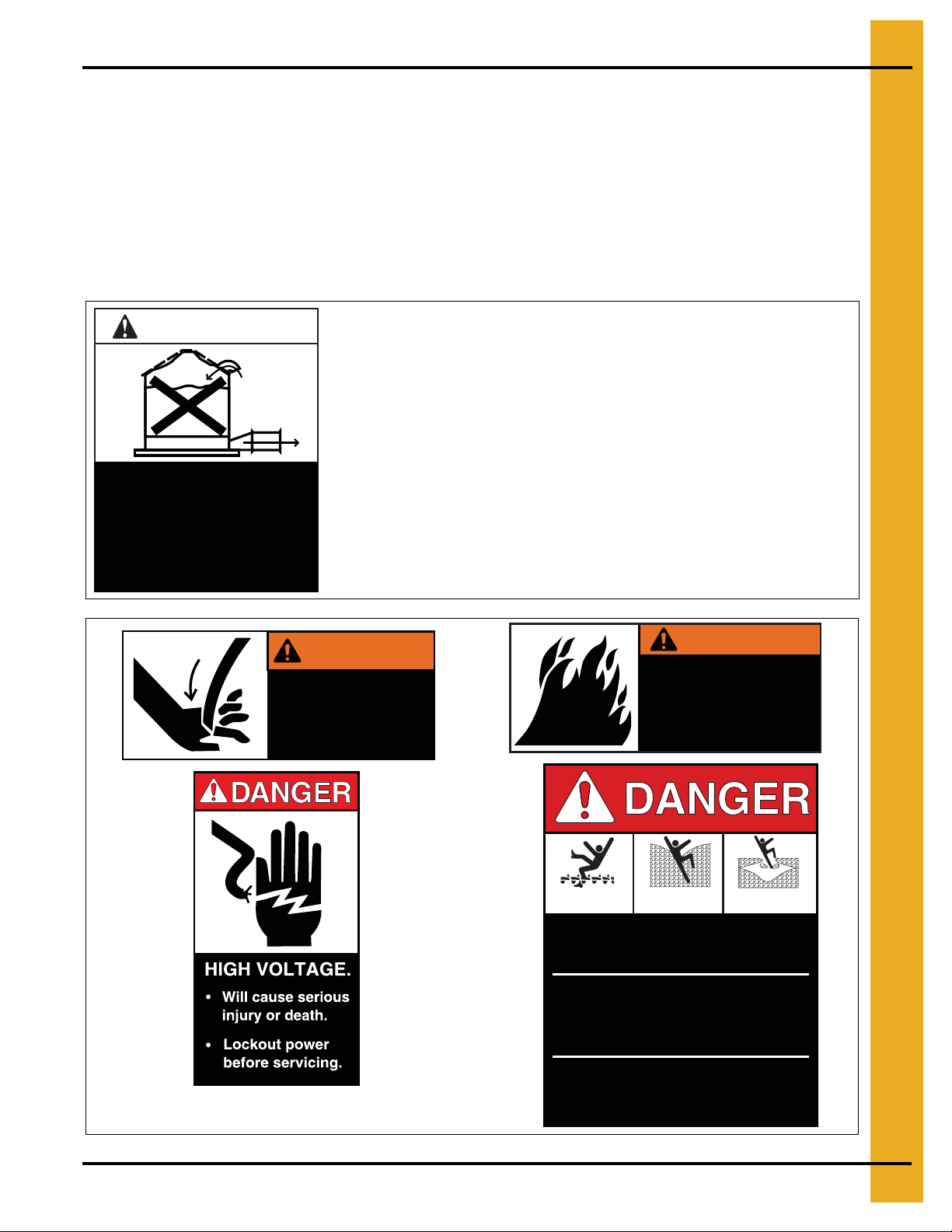
Wear Protective Clothing
Wear close fitting clothing and safety equipment appropriate
to the job.
Remove all jewelry.
Long hair should be tied up and back.
Safety glasses should be worn at all times to protect eyes
from debris.
Wear gloves to protect your hands from sharp edges on
plastic or steel parts.
Wear steel toe boots to help protect your feet from falling
debris. Tuck in any loose or dangling shoe strings.
A respirator may be needed to prevent breathing potentially
toxic fumes and dust.
Eye Protection
Gloves
Steel Toe Boots
Respirator
Hard Hat
Wear hard hat to help protect your head.
Wear appropriate fall protection equipment when working at
elevations greater than six feet (6').
8 PNEG-823 Deluxe Downwind Heater
Fall Protection
Page 9
2. Decals
The GSI Group recommends contacting your local power company, and having a representative survey
the installation so the wiring is compatible with their system, and adequate p ower is supplied to the unit.
If a decal is damaged or missing, contact:
GSI Decals
1004 E. Illinois St.
Assumption, IL. 62510
Phone: 217-226-4421
A free replacement will be sent to you.
Roof Damage Warning and Disclaimer
CAUTION!
Excessive vacuum (or pressure) may
damage roof. Use positive aeration
system. Make sure all roof vents are
open and unobstructed. Start roof
fans when supply fans are started.
Do not operate when conditions exist
that may cause roof vent icing.
DC-969
Stay clear of rotating
blade. Blade could start
automatically. Can cause
serious injury. Disconnect
power before servicing.
GSI does not warrant any roof damage caused by excessive
vacuum or internal pressure from fans or other air moving
systems. Adequate ventilation and/or “Makeup Air” devices
should be provided for all powered air handling systems. GSI
does not recommend the use of downward flow systems (suction).
Severe roof damage can result from any blockage of air
passages. Running fans during high humidity/cold weather
conditions can cause air exhaust or intake ports to freeze.
WARNING
DC-1225
WARNING
Flame and pressure beyond
door can cause serious
injury. Do not operate with
service door removed. Keep
head and hands clear.
DC-1227
Rotating flighting will
kill or dismember.
Flowing material will
trap and suffocate.
Crusted material will
collapse and suffocate.
Keep clear of all augers.
DO NOT ENTER this bin!
If you must enter the bin:
1. Shut off and lock out all power.
2. Use a safety harness and safety line.
3. Station another person outside the bin.
4. Avoid the center of the bin.
5. Wear proper breathing equipment or respirator.
DC-1224
PNEG-823 Deluxe Downwind Heater 9
Failure to heed these
warnings will result in
serious injury or death.
DC-GBC-1A
Page 10
3. Heater Installation
Machine to Earth Ground
It is very important that a machine to earth ground rod be installed at the fan. This is true even if there is
a ground at the pole 15' away. This ground needs to be as close to the fan as possible, but no more than
8' away. The ground rod should be connected to the fan control panel with at least a #6 solid bare copper
ground wire, or in accordance with local requirements. The machine to earth ground provides additional
safety if there is a short. It also provides the grounding necessary for long life and operation of the solid
state circuit boards used on control circuits and the electronic ignition systems.
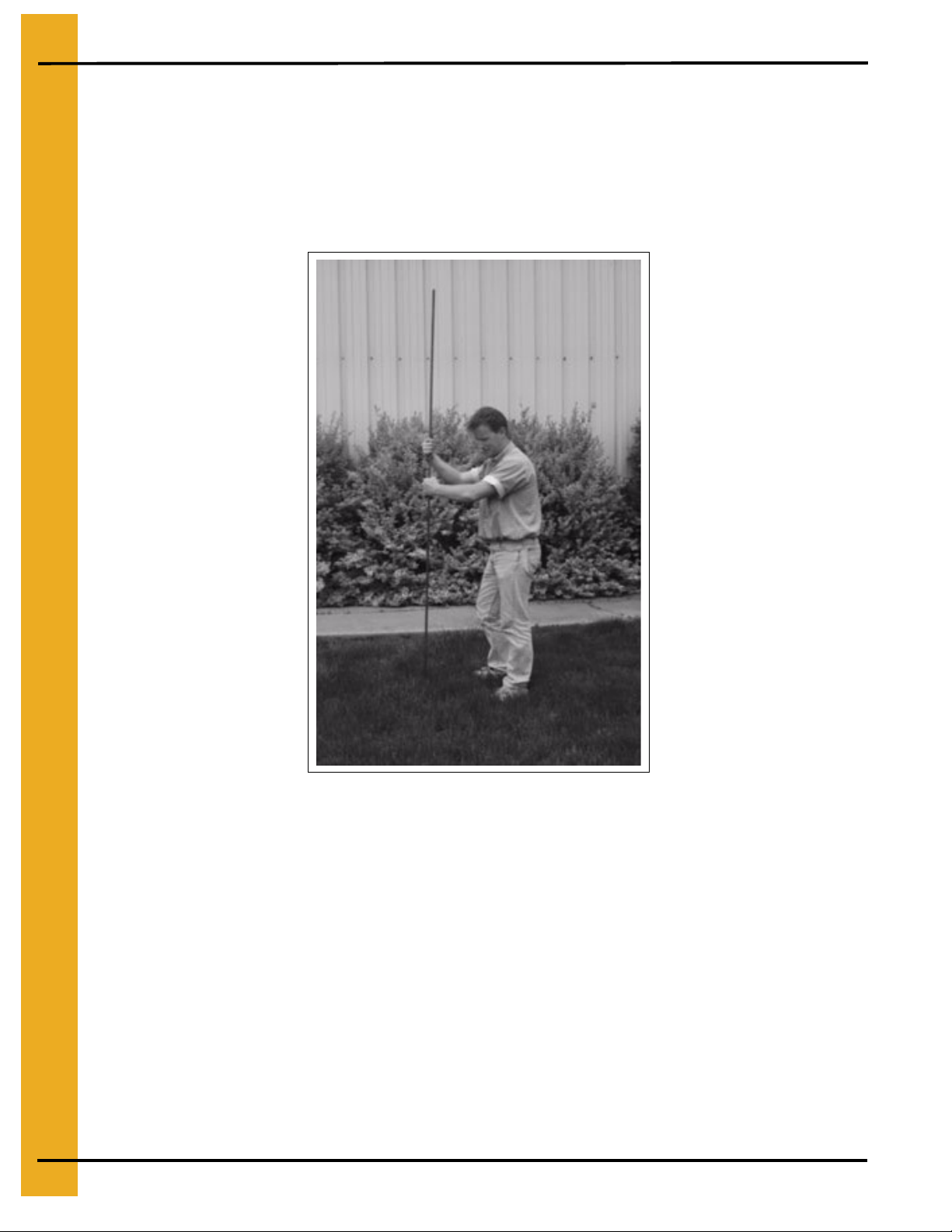
Figure 3A
Dig a hole large enough to hold one (1) or two (2) gallons of water. Work the ground rod into the
earth until it is completely in the ground.
Proper Installation of the Ground Rod
(Ground rods and wires are not supplied by Airstream). It is recommended that the rod not be driven into
dry ground. The following steps ensure proper ground rod installation:
1. Dig a hole large enough to hold one (1) to two (2) gallons of water.
2. Fill hole with water.
3. Insert rod through water and jab it into the ground.
4. Continue jabbing the rod up and down, the water will work its way down the hole, making it possible
to work the rod completely into the ground. This method of installing the rod gives a good
conductive bond with the surrounding soil.
10 PNEG-823 Deluxe Downwind Heater
Page 11
3. Heater Installation
Proper Installation of the Ground Rod (Continued)
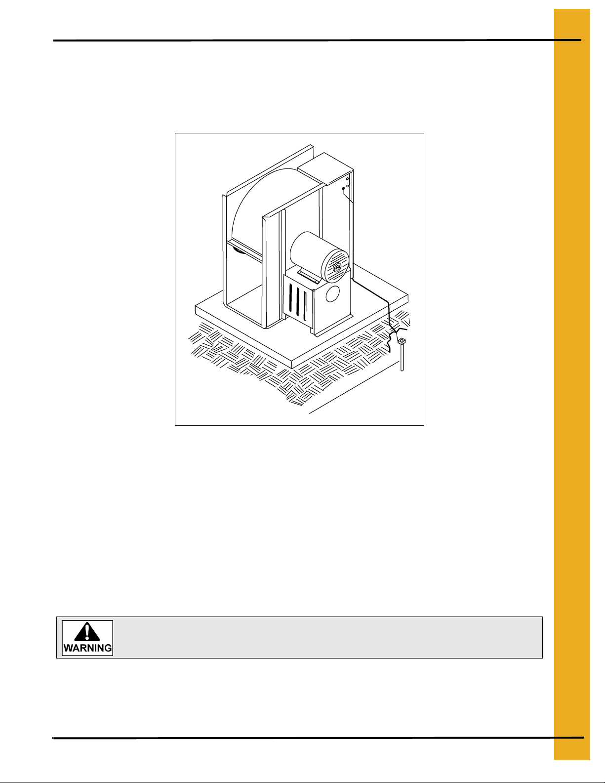
5. Connect the bare copper ground wire to the rod with the proper ground rod clamp.
6. Connect the bare ground wire to the fan control boxes with a grounding lug. (See Figure 3B.)
7. Ground wire must not have any breaks or splices. Insulated wire is not recommended for grounding.
Figure 3B
Use a #6 or approved size bare copper ground wire. Install a 5/8" diameter 8' long copper-clad
ground rod, 2' away from the foundation and 1' below the surface of the ground or in accordance
with local requirements.
Previously Installed Units
It is recommended that previously installed units be checked to see that a machine to earth ground
on Page 10 has been installed by an electrician.
Standard electrical safety practices and codes should be used when working with a heater. Refer to the
National Electric Code Standard Handbook by the National Fire Protection Association. A qualified
electrician should make all wiring installations.
Always disconnect and lock out power before working on or around heater.
IMPORTANT: Do not use propane tan ks that have previously been used for ammonia unless they have
been purged according to procedures of the National LP Association.
Fuel supply system must comply with local codes for LP gas installation.
PNEG-823 Deluxe Downwin d Heater 11
Page 12

3. Heater Installation
Fuel Connection
Liquid Propane Models
1. LP models are designed to run on liquid propane with liquid draw from the propane tank. Avoid
using propane supply tanks that have been used for vapor draw for long periods of time. When
using liquid draw systems any moisture that may be present in tank or lines may freeze when
system is used in cold weather. To avoid this situation, purge the system with methanol.
2. Run proper size line
service person inspect installation to be sure that everything is installed according to local codes
and ordinances.
3. After installation is complete check all connections for leaks with liquid detergent or comparable.
Wear rubber gloves and eye protection. Avoid contact with liquid propane. DO NOT USE FLAME
FOR LEAK TESTING.
(see Specification on Page 13)
to liquid pipetrain on heater. Have a qualified gas
Propane Vapor Models
1. Propane vapor models are designed to run directly off of a supply tank or from a separate
external vaporizer.
2. Run proper size line (see Specification on Page 13) to pipetrain on heater. Have a qualified gas
service person inspect installation to be sure that everything is installed according to local codes
and ordinances.
3. After installation is complete check all connections for leaks. DO NOT USE FLAME FOR
LEAK TESTING.
Natural Gas Models
1. Natural gas models are designed to run directly off of a supply tank or from a separate external vaporizer.
2. Run proper size line (see Specification on Page 13) to pipetrain on heater. Have a qualified gas
service person inspect installation to be sure everything is installed according to local codes
and ordinances.
3. After installation is complete check all connections for leaks. DO NOT USE FLAME FOR
LEAK TESTING.
12 PNEG-823 Deluxe Downwind Heater
Page 13
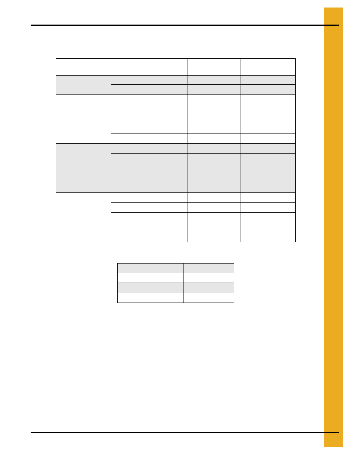
Heater Specifications
4. Installation
Centrifugal Heater Specifications
All Models
Liquid Models
Vapor Models
Natural Gas Models
High-Temperature
Model
BTU Rating 4000000 500000
Weight 145 135
Maximum Fuel Flow (GPH) 43 N/A
Orifice Size 0.25 N/A
Minimum Operating Pressure 3 N/A
Maximum Operating Pressure 30 N/A
Minimum Line Size 3/8" N/A
Maximum Fuel Flow (CFH) 1590 210
Orifice Size 0.25 0.109
Minimum Operating Pressure 2 1
Maximum Operating Pressure 30 15
Minimum Line Size 1" 1/2"
Maximum Fuel Flow (CFH) 4200 500
Orifice Size 0.375 0.156
Minimum Operating Pressure 1 1
Maximum Operating Pressure 15 7
Minimum Line Size 1-1/4" 1"
Low-Temperature
Model
Heater Dimensional Specifications
Heater Size 10-15 20-30 40
Inside Height 30-1/4" 33-1/4" 33-1/4"
Inside Width 19-1/2" 21-3/4" 23-11/16"
Inside Length 24" 24" 24"
Plenum Thermostat Mounting
The plenum thermostat is the 4 x 4 white box with knob that is preconnected to heater when heater is
ordered with thermostat.
1. 24" to the right side of the transition, drill one (1) 3/8" hole (High-Temperature) or 1-1/2" hole
(Low-Temperature) in the center of the plenum in a valley (4.00" corrugation) or hill
(2.66" corrugation) on bin sidewall.
2. Insert the probe through the hole.
3. Position the housing so that the tabs are vertical, and the cord exits the housing horizontally.
4. Use four (4) self-drilling screws to mount the housing to the bin sidewall.
5. Caulk between the housing and the sidewall to seal.
PNEG-823 Deluxe Downwind Heater 13
Page 14

4. Installation
Plenum Thermostat Mounting (Continued)
Figure 4A Plenum Thermostat Mounting on Bin Wall
Transition High-Limit Installation
1. Mark location on transition one (1) foot up from the bottom (entrance collar) and centered in
the transition.
2. Drill or knock out 7/8" diameter hole on marked location.
3. Install transition High-Limit using supplied self-drilling screws.
Figure 4B The transition connecting the heater to the
bin with the plenum thermostat in place.
14 PNEG-823 Deluxe Downwind Heater
Page 15

5. Bin Configuration
Figure 5A
IMPORTANT: When mounting two (2) heaters on a bin it is imperative that they be situated as in above
Figure 5A. Plenum thermostat must be to the right of master heater and master heater
must be to the right of slave heater.
Operating Temperature Table
IMPORTANT: Do not exceed plenum temperatures listed in table.
Low-Temperature Batch
Corn 5°-20° Above Ambient Temp. 120° 140° 160°
Rice 5°-10° Above Ambient Temp. 100° 100° Not Recommended
Beans and Wheat 5°-20° Above Ambient Temp. 110° 120° Not Recommended
High-Temperature
Batch Dry No Stirring
This table is not intended as a drying guide. It should be used as a reference for setting maximum
plenum temperature for safe operation.
PNEG-823 Deluxe Downwind Heater 15
High-Temperature
with Stirring
Continuous Flow
(Recirculating)
Page 16

6. Second Heater Installation
For Units Using HF-7318 Control Board
Two (2) Deluxe heaters may be connected to one (1) grain drying system and wired so they cycle
together. One (1) of the heaters should have a thermostat connected to it as per the installation
instructions. That heater will be referred to as the master. The other heater (without the thermostat) will
be referred to as the slave.
Installation for Standard Units
1. Install relay base (TD-100283) in master heater control box.
2. Connect wire between terminal 6 on circuit board and terminal 14 on relay base in master heater.
3. Connect wire between terminal 13 on relay base and terminal 8 on circuit board in master heater.
4. Run two (2) wires (18 gauge) between master and slave heaters.
5. Connect wires to terminal 5 and 9 (points A and B) on relay base in master heater.
6. Connect wire from terminal 9 in master to terminal 14 (point F) in slave unit.
7. Connect wire from terminal 5 in master to terminal 15 (point E) in slave unit.
8. Install relay (TD-100282) in relay base.
Additional Steps for High-Low Units
1. Run two (2) wires (18 gauge) between master and slave unit.
2. Connect wires to terminal 21 and 22 (points C and D) on circuit board in main heater.
3. Connect wire from terminal 21 in master to terminal 12 (point H) in slave unit.
4. Connect wire from terminal 22 in master to terminal 13 (point G) in slave unit.
5. Install relay (TD-100282) in relay base.
Figure 6A The HF-7318 Control Board
16 PNEG-823 Deluxe Downwind Heater
Page 17

6. Second Heater Installation
Electrical Installation (230V Fans)
1. Connect power cord to fan control box.
2. Make field connections of wires in fan box as shown in Figure 6B.
3. Connect deluxe thermostat control (optional) in heater box as shown in Figure 6B.
IMPORTANT: Heater must be interlocked with fan for safe operation.
IMPORTANT: Thermostat must be installed for safe operation.
Figure 6B 230 Volt Fan Control Box
PNEG-823 Deluxe Downwind Heater 17
Page 18

6. Second Heater Installation
Electrical Installation (460V Fans)
1. Connect power cord to fan control box.
2. Make field connections of wires in fan box as shown in Figure 6C. 110V power supply or
0.5 KVA 460V to 110V transformer must be used to supply power for heater.
3. Connect deluxe thermostat control (optional) in heater box as shown in Figure 6B on Page 17.
IMPORTANT: Heater must be interlocked with fan for safe operation.
IMPORTANT: Thermostat must be installed for safe operation.
Figure 6C 460 Volt Fan Control Box
18 PNEG-823 Deluxe Downwind Heater
Page 19

7. Wiring Diagram
PNEG-823 Deluxe Downwind Heater 19
Page 20

8. Operating Procedure
Cycling Heater Operation
1. Thermostat must be wired into heater control box for heater to operate.
2. Open all manual shut off valves to heater unit.
3. Start fan. This will supply power to heater.
4. Turn thermostat dial to its highest setting.
5. Turn toggle switch ON.
6. Heater should now be lit. If not check to see that all gas is ON.
7. Set thermostat to desired setting (see deluxe thermostat manual for adjusting deluxe
thermostat control.)
8. Gas pressure should be adjusted so burner is on 75 percent of the time.
9. Watch as burner goes through a few cycles, to be sure that it is operating properly.
High-Low Heater Operation
1. Thermostat must be wired into heater control box for heater to operate.
2. Open all manual shut off valves to heater unit.
3. Start fan. This will supply power to heater.
4. Turn thermostat dial to its highest setting.
5. Turn toggle switch ON.
6. After 20 seconds both red lights should light up indicating power to the control circuit.
7. Heater should now be lit. If not, check to see that all gas is ON.
8. Open Low-Fire ball valve all the way.
9. Turn thermostat dial back slowly until heater cycles to low flame.
10. Adjust ball valve so that low flame pressure is at desired setting.
11. Turn thermostat dial to desired editing and wait for bin plenum to come up to temperatu re. Heater
should cycle to low flame after a few minutes. If heater does not cycle to low flame increase
high flame gas pressure.
12. Low flame should be adjusted so that temperature drops slowly until burner goes back to high flame.
13. Watch as burner goes through a few cycles, to be sure that it is operating properly.
20 PNEG-823 Deluxe Downwind Heater
Page 21

8. Operating Procedure
Modulating Valve Operation
1. The modulating valve regulates gas flow through the heater based on sensing unit in the plenum,
and maintains a constant drying air temperature.
2. The sensing bulb of the modulating valve should be mounted through the bin wall with the side
reading “top” up. The bulb reacts to temperature. It changes the amount of gas (increase or
decrease), burning warmer or cooler depending on the position of the valve SET POINT. If the bulb
is cooler than it was at the SET POINT, the bulb senses the cooler temperature and opens the
valve further so more heat is applied to the drying air. If the bulb is warmer than it was at th e SET
POINT, the valve closes further and reduces the temperature until the air is at the valve SET
POINT.
3. It is important that the pressure regulator be set high enough to allow the modulating valve to
deliver enough gas to maintain the plenum temperature necessary. The regulator is normally
factory set at 15 PSI (propane units). To set the regulator, run the heater and turn the modulating
valve
T-handle in. This gets full line pressure to the burner. Then adjust regulator to read 15 PSI
(depending on the plenum temperature needed).
4. Turn the fan and heater ON. To set the modulating valve, turn the T-handle out (counterclockwise)
until loose and wait a few minutes for the plenum temperature to equalize. When the tempera ture
under the bin has equalized, gradually turn T-handle in (clockwise) about 1/2 turn at a time.
Wait until temperature under bin has equalized as before. If temperature under bin is less than the
desired temperature, continue turning T-handle in, increasing gas flow and waiting for plenum
temperature to equalize until the desired temperature is the stable temperature of the plenum. If
temperature under bin is the same 10 minutes after you last made any adjustments to the T-handle
you can be certain that the temperature under the bin is the SET POINT of the valve. One (1) turn
of the T-handle equals approximately 7°F of temperature.
5. The valve will now keep the plenum temperature at the set point regardless of ambient conditions
as long as humidistat or thermostat do not shut down the heater. A bypass orifice is used to
maintain a small flame when outside temperature is near or above the set point of the valve. The
bypass insures steady application of heat at minimum gas flow operation. Bypass orifice will only
operate correctly if pressure regulator is set correctly.
6. To observe how the modulating valve increases the efficiency of bin drying, check the gas pressure
of the unit in the morning and compare to the pressure read mid-afternoon. If the ambient (outside)
temperature is significantly greater later in the day (as normal), the gas pressure will be less. Since
less heat is required to maintain the same temperature in the plenum, the modulating valve will
have reduced the amount of gas used by the heater.
PNEG-823 Deluxe Downwind Heater 21
Page 22

8. Operating Procedure
10 HP-15 HP Units BTUs per Gauge Pressure (PSI) Propane
Models (Approximate)
High-Temperature 10 HP-15 HP 7/32" (0.219") Orifice
Operating Pressure (PSI)
2 4 6 8 10 12 14 15
All Models 816013 1148640 1409477 1632026 1825859 1995762 2153700 2227883
Gauge Pressure (PSI) Required to Maintain Temperature (Approximate)
(10 HP-15 HP High-Temperature Propane Units Only)
Fan Model Static Pressure
2" 2 4 6 8 10 13
10 HP
15 HP
4" 1 3 5 6 8 11 14
6" 1 1 3 5 6 8 10
2" 3 6 9 12 15
4" 3 5 7 10 13
6" 2 3 5 6 9 11 14
60 80 100 120 140 160 180
Heat Rise (°F)
10 HP-15 HP Units BTUs per Gauge Pressure (PSI) Natural Gas
Models (Approximate)
High-Temperature 10 HP-15 HP 11/32" (0.344") Orifice
Operating Pressure (PSI)
12 3 4 567
All Models 859104 1218432 1489296 1718208 1921584 2107632 2276352
Gauge Pressure (PSI) Required to Maintain Temperature (Approximate)
(10 HP-15 HP High-Temperature Natural Gas Units Only)
Fan Model Static Pressure
2" 1 1.75 2.5 3.5 4.75 6
10 HP
15 HP
22 PNEG-823 Deluxe Downwind Heater
4" 0.75 1.25 2 2.75 3.75 4.75 6
6" 0.5 1 1.5 2 2.75 3.5 4.25
2" 1.5 2.5 3.75 5.5
4" 1.25 2 3 4.25 5.75
6" 0.75 1.25 2 2.75 3.75 5 6
60 80 100 120 140 160 180
Heat Rise (°F)
Page 23

8. Operating Procedure
20 HP-40 HP Units BTUs per Gauge Pressure (PSI) Propane
Models (Approximate)
High-Temperature 20 HP-40 HP 5/16" (0.313") Orifice
Operating Pressure (PSI)
2 4 6 8 10 12 14 15
All Models 1663135 2345140 2878779 3328663 3721115 4068100 4393548 4541914
Gauge Pressure (PSI) Required to Maintain Temperature (Approximate)
(20 HP-40 HP High-Temperature Propane Units Only)
Fan Model Static Pressure
2" 2 2 4 5 7 8 10
20 HP
25 HP
30 HP
40 HP
4" 1 2 3 4 5 7 8
6" 1 2 3 4 5 6 7
2" 2 3 5 7 9 12 15
4" 2 3 4 6 8 10 13
6" 2 2 4 5 6 8 10
2" 2 4 6 8 11 15
4" 2 4 5 7 10 13
6" 2 3 4 6 8 10 13
2" 3 6 8 12
4" 3 5 7 11 14
6" 3 4 7 9 12
Heat Rise (°F)
60 80 100 120 140 160 180
PNEG-823 Deluxe Downwind Heater 23
Page 24

8. Operating Procedure
20 HP-40 HP Units BTUs per Gauge Pressure (PSI) Natural Gas
Models (Approximate)
High-Temperature 20 HP-40 HP 15/32" (0.469") Orifice
Operating Pressure (PSI)
12 34567
All Models 1597824 2266320 2770656 3195648 3573216 3919776 4234416
Gauge Pressure (PSI) Required to Maintain Temperature (Approximate)
(20 HP-40 HP High-Temperature Natural Gas Units Only)
Fan Model Static Pressu re
2" 0.75 1.25 1.75 2.5 3.25 4.25 5.5
20 HP
25 HP
30 HP
40 HP
4" 0.5 1 1.5 2 2.75 3.5 4.5
6" 0.5 0.75 1.25 1.75 2.25 3 3.75
2" 1 1.75 2.25 3.5 4.75 6.25
4" 0.75 1.5 2.25 3.25 4 5.25 6.25
6" 0.5 1.25 1.75 2.5 3.25 4.25 5.5
2" 1.25 2 3 4.5 6
4" 1 1.75 2.75 3.75 5 7
6" 0.75 1.5 2.25 3 4 5.25 7
2" 1.75 3 4.5 6.25
4" 1.5 2.5 4 5.5
6" 1.25 2.25 3.5 4.75 6.75
60 80 100 120 140 160 180
Heat Rise (°F)
Low-Temperature Units BTUs per Gauge Pressure (PSI) Propane
Models (Approximate)
Low-Temperature all HP 7/64" (0.109") Orifice
Operating Pressure (PSI)
2 4 6 8 10 12 14 15
All Models 203405 287160 351771 409203 457063 497744 538425 555176
Low-Temperature Units BTUs per Gauge Pressure (PSI) Natural
Gas Models (Approximate)
Low-Temperature all HP 5/32" (0.156") Orifice
Operating Pressure (PSI)
12 3 4 567
All Models 177840 251712 308256 355680 397632 435936 470592
24 PNEG-823 Deluxe Downwind Heater
Page 25

8. Operating Procedure
Adjusting the Vaporizer
1. Vaporizer should be adjusted so the vapor pipetrain runs warm to the touch (100°F-120°F).
2. Loosen 5/16" bolt on adjustment bracket.
3. Swivel vaporizer away from flame if running too hot, closer to flame if too cold.
4. Move vaporizer only 1" at a time and allow a few minutes for temperature to equalize.
5. Tighten 5/16" bolt and watch heater run for several minutes to verify adjustment.
Figure 8A Vaporizer Coil Adjustment Positions
PNEG-823 Deluxe Downwind Heater 25
Page 26

9. Parts List
1. DW Propane Vapor High-Fire Pipetrain Components
2. DW Propane Vapor High-Low Fire Pipetrain Components
3. DW Propane Vapor Modulating Pipetrain Components
4. DW NG High-Fire Pipetrain Components
5. DW NG High-Low Fire Pipetrain Components
6. DW NG Modulating Pipetrain Components
7. DW LP High-Fire Pipetrain Components
8. DW LP High-Low Pipetrain Components
9. DW LP Modulating Pipetrain Components
10. 40 HP DW High-Temperature Heater Parts
11. 40 HP DW Low-Temperature Heater Parts
12. DW Gas Heater Control Box Parts
13. DW Propane Vapor Pipetrain Parts
14. DW Propane Vapor High-Low Pipetrain Parts
26 PNEG-823 Deluxe Downwind Heater
Page 27

DW Propane Vapor High-Fire Pipetrain Components
9. Parts List
Ref # Part # Description
1 HH-1251 Strainer 1/2" Y 250# WOG SCH 80 Black
2 TFC-0030 Valve 1/2" NPT Ball, Bronze
3 THH-4111 Valve 1/4" NPT 50 PSI Relief
4 TFC-0023 Regulator 1/2" NPT 0-30 PSI
5 TFC-0032 Valve 1/2" NPT Solenoid
6 TFC-0030 Valve 1/2" Fi ring
7 HH-2984 Gauge 0-30# Pressure LP
PNEG-823 Deluxe Downwind Heater 27
Page 28

9. Parts List
DW Propane Vapor High-Low Fire Pipetrain Components
Ref # Part # Description
1 HH-1251 Strainer 1/2" Y 250# WOG SCH 80 Black
2, 6 TFC-0030 Valve 1/2" NPT Ball, Bronze
3 THH-4111 Valve 1/4" NPT 50 PSI Relief
4 TFC-0023 Regulator 1/2" NPT 0-30 PSI
5, 7 TFC-0032 Valve 1/2" NPT Solenoid
8 TFC-0030 Valve 1/2" Fi ring
9 HH-2984 Gauge 0-30# Pressure LP
28 PNEG-823 Deluxe Downwind Heater
Page 29

DW Propane Vapor Modulating Pipetrain Components
9. Parts List
Ref # Part # Description
1 HH-1251 Strainer 1/2" Y 250# WOG SCH 80 Black
2 TFC-0030 Valve 1/2" NPT Ball, Bronze
3 THH-4111 Valve 1/4" NPT 50 PSI Relief
4 TFC-0023 Regulator 1/2" NPT 0-30 PSI
5 TFC-0032 Valve 1/2" NPT Solenoid
6 TFC-0030 Valve 1/2" Fi ring
7 HH-2984 Gauge 0-30# Pressure LP
8 HH-2653 Valve Modulating
PNEG-823 Deluxe Downwind Heater 29
Page 30

9. Parts List
DW NG High-Fire Pipetrain Components
Ref # Part # Description
1 D67-0008 Strainer 3/4" Y 250# WOG SCH 80 Black
2 TFC-0051 Valve 3/4" NPT Ball, Bronze
3 THH-4111 Valve 1/4" NPT 50 PSI Relief
4 TFC-0020 Regulator 3/4"
5 TFC-0081 Valve 3/4" NPT Solenoid
6 TFC-0051 Valve 3/4" Fi ring
7 D08-0022 Gauge 0-15# Pressure
30 PNEG-823 Deluxe Downwind Heater
Page 31

DW NG High-Low Fire Pipetrain Components
9. Parts List
Ref # Part # Description
1 D67-0008 Strainer 3/4" Y 250# WOG SCH 80 Black
2, 6 TFC-0051 Valve 3/4" NPT Ball, Bronze
3 THH-4111 Valve 1/4" NPT 50 PSI Relief
4 TFC-0020 Regulator 3/4"
5, 7 TFC-0081 Valve 3/4" NPT Solenoid
8 TFC-0051 Valve 3/4" Fi ring
9 D08-0022 Gauge 0-15# Pressure
PNEG-823 Deluxe Downwind Heater 31
Page 32

9. Parts List
DW NG Modulating Pipetrain Components
Ref # Part # Description
1 D67-0008 Strainer 3/4" Y 250# WOG SCH 80 Black
2 TFC-0051 Valve 3/4" NPT Ball, Bronze
3 THH-4111 Valve 1/4" NPT 50 PSI Relief
4 TFC-0020 Regulator 3/4"
5 TFC-0081 Valve 3/4" NPT Solenoid
6 TFC-0051 Valve 3/4" Fi ring
7 D08-0022 Gauge 0-15# Pressure
8 HH-2653 Valve Modulating
32 PNEG-823 Deluxe Downwind Heater
Page 33

DW LP High-Fire Pipetrain Components
9. Parts List
Ref # Part # Description
1 TFC-0027 Valve 1/4" NPT 250 PSI Relief
2 HH-1251 Strainer 1/2" Y 250# WOG SCH 80 Black
3 TFC-0030 Valve 1/2" NPT Ball, Bronze
4 TFC-0092 Valve 1/2" NPT Solenoid LP Gas
5 THH-4111 Valve 1/4" NPT 50 PSI Relief
6 TFC-0023 Regulator 1/2" NPT 0-30 PSI
7 TFC-0032 Valve 1/2" NPT Solenoid
8 TFC-0030 Valve 1/2" Fi ring
9 HH-2984 Gauge 0-30# Pressure LP
10 HH-7013 200° Vapor High-Limit
11 CD-0197 Vaporizer Coil
PNEG-823 Deluxe Downwind Heater 33
Page 34

9. Parts List
DW LP High-Low Pipetrain Components
Ref # Part # Description
1 TFC-0027 Valve 1/4" NPT 250 PSI Relief
2 HH-1251 Strainer 1/2" Y 250# WOG SCH 80 Black
3 TFC-0030 Valve 1/2" NPT Ball, Bronze
4 TFC-0092 Valve 1/2" NPT Solenoid LP Gas
5 THH-4111 Valve 1/4" NPT 50 PSI Relief
6 TFC-0023 Regulator 1/2" NPT 0-30 PSI
7 TFC-0032 Valve 1/2" NPT Solenoid
8 TFC-0030 Valve 1/2" Fi ring
9 HH-2984 Gauge 0-30# Pressure LP
10 HH-7013 200° Vapor High-Limit
11 CD-0197 Vaporizer Coil
34 PNEG-823 Deluxe Downwind Heater
Page 35

DW LP Modulating Pipetrain Components
9. Parts List
Ref # Part # Description
1 TFC-0027 Valve 1/4" NPT 250 PSI Relief
2 HH-1251 Strainer 1/2" Y 250# WOG SCH 80 Black
3 TFC-0030 Valve 1/2" NPT Ball, Bronze
4 TFC-0092 Valve 1/2" NPT Solenoid LP Gas
5 THH-4111 Valve 1/4" NPT 50 PSI Relief
6 TFC-0023 Regulator 1/2" NPT 0-30 PSI
7 TFC-0032 Valve 1/2" NPT Solenoid
8 TFC-0030 Valve 1/2" Fi ring
9 HH-2984 Gauge 0-30# Pressure LP
10 HH-2653 Modulating Valve
11 HH-7013 200° Vapor High-Limit
12 CD-0197 Vaporizer Coil
PNEG-823 Deluxe Downwind Heater 35
Page 36

9. Parts List
40 HP DW High-Temperature Heater Parts
Ref # Part # Description Ref # Part # Description
1 HF-7472 40 HP Housing Assembly 15 HF-7083 1/4" Orifice (Propane)
2 HF-7288 Access Side Cover 15 HF-7034 3/8" Orifice (Natural Gas)
3 HF-7380 Plastic View Window 16 HF-7027 Orifice Tube Weldment
4 HF-7379 Access Panel Cover Plate 17 THH-4071 1/2" Elbow
5 HF-7287 Access Panel Holders 18 HH-3854 1/2" x 6" Nipple
6 HF-7140 40 HP Diverter Plate 19 HH-3670 1/2" x 2-1/2" Nipple
7 CD-0238 Ignitor (2 Required) 20 S-7259 5/16" U-Bolt
8 HF-7201 Ignitor Clamp Half (2 Required) 21 HF-7079 Diverter Angle Cover
9 HF-7204 Ignitor Bracket 22 HF-7020 Vaporizer Support Weldment
10 HF-7102 20-40 Diverter Angle 23 HF-7297 Burner Support Plate
11 CD-0187 Flame Sensor Bracket (Deluxe, SR 2000) 24 HF-7032 Vapor Cover Plate
12 THH-4179 Flame Sensor (Deluxe, SR 2000) 25 HF-7023 High-Fire Burner Assembly
13 HF-7304 40 Burner Brace N/S HF-7261 10 HP-40 HP Spark Plug Wire
14 HH-7035 1-1/4" Coupling N/S HF-7263 10 HP-40 HP Flame Probe Wire
36 PNEG-823 Deluxe Downwind Heater
Page 37

40 HP DW Low-Temperature Heater Parts
9. Parts List
Ref # Part # Description Ref # P art # Description
1 HF-7472 40 HP Housing Assembly 15 HF-7071 Low-Fire Diverter
2 HF-7288 Access Side Cover 16 HF-7070 Low-Fire Burner Assembly
3 HH-2020 Plastic View Window 17 HF-7035 7/64" Orifice (Propane)
4 HF-6914 Access Cover Plate 17 HF-7036 5/32" Orifice (Natural Gas)
5 HF-7287 Access Panel Holders 18 HF-7069 Low-Fire Orifice Weldment
6 HF-7140 40 Diverter Plate 19 THH-4071 1/2" Elbow
7 CD-0238 Ignitor (2 Required) 20 HH-3854 1/2" x 6" Nipple
8 HF-7201 Ignito r Clamp Half (2 Required) 21 HH-3670 1/2" x 2-1/2" Nipple
9 HF-7204 Ignitor Bracket 22 S-7259 5/16" U-Bolt
10 HF-7102 20-40 Diverter Angle 23 HF-7079 Diverter Angle Cover
11 CD-0187 Flame Sensor Bracket (Deluxe, SR 2000) 24 HF-7297 Burner Support Plate
12 THH-4179 Flame Sensor (Deluxe, SR 2000) 25 HF-7032 Vapor Cover Plate
13 HF-7304 40 Burner Brace N/S HF-7261 10 HP-40 HP Spark Plug Wire
14 HF-7072 Low-Fire Diverter Spacer N/S HF-7263 10 HP-40 HP Flame Probe Wire
PNEG-823 Deluxe Downwind Heater 37
Page 38

9. Parts List
DW Gas Heater Control Box Parts
Ref # Part # Description
1 HF-7315 Control Box Housing
2 HH-7015 Snap Trak
3 HF-7318 Circuit Board Assembly
4 HH-1487 Ignition Transformer
5 HH-1092 High-Limit Switch 180°
6 F-942 Control Box Lid
7 HH-1442 Toggle Switch
8 TFH-2021 Red Light (110V)
9 DC-1166 Decal Deluxe Heater Front Panel
10 HF-7455 High-Limit Switch Box Bottom
11 FH-1310 Cord Connector
12 HF-7439 High-Limit Switch 250°
13 HF-7454 High-Limit Switch Box Top
14 HF-7414 Recessed Plastic Plug
38 PNEG-823 Deluxe Downwind Heater
Page 39

DW Propane Vapor Pipetrain Parts
9. Parts List
Ref # Part # Description
1 TFC-0023 1/2" 0-30 PSI Regulator (Deluxe, SR 2000)
2 HH-3670 1/2" x 2-1/2" Nipple
3 TFC-0032 1/2" Solenoid (Deluxe, SR 2000)
4 HH-2029 1/2" x 1-1/2" Nipple
5 S-3853 1/2" x 1/4" x 1/2" Tee
6 HH-2984 30 PSI Gauge
7 HH-2653 Modulating Valve
8 HH-1251 1/2" Strainer
9 HH-2028 1/2" Female Union
PNEG-823 Deluxe Downwind Heater 39
Page 40

9. Parts List
DW Propane Vapor High-Low Pipetrain Parts
Ref # Part # Description
1 TFC-0023 1/2" 0-30 PSI Regulator (Deluxe, SR 2000)
2 HH-3670 1/2" x 2-1/2" Nipple
3 TFC-0032 1/2" Solenoid (Deluxe, SR 2000)
4 HH-2029 1/2" x 1-1/2" Nipple
5 HH-1453 1/2" x 1/2" x 1/2" Tee
6 THH-4067 1/2" Street Elbow
7 THH-4127 1/2" Cross
8 THH-4032 1/2" x 1/4" Reducer Bushing
9 HH-2984 30 PSI Gauge
10 TFC-0030 1/2" Ball Valve
11 HH-7019 1/2" Gas Hose
12 HH-1251 1/2" Strainer
13 HH-2028 1/2" Female Union
40 PNEG-823 Deluxe Downwind Heater
Page 41

Limited Warranty
The GSI Group, LLC. (“GSI”) warrants products which it manufactures to be free of defects in materials
and workmanship under normal usage and conditions for a period of 12 months after sale to the original
end-user or if a foreign sale, 14 months from arrival at port of discharge, whichever is earlier. The enduser’s sole remedy (and GSI’s only obligation) is to repair or replace, at GSI’s option and expense,
products that in GSI’s judgment, contain a material defect in materials or workmanship. Expenses
incurred by or on behalf of the end-user without prior written authorization from the GSI Warranty Group
shall be the sole responsibility of the end-user.
Warranty Extensions: The Limited Warranty period is extended for the following products:
Product Warranty Period
AP Fans and
Flooring
Cumberland
Feeding/Watering
Systems
Grain Systems
Grain Systems
Farm Fans
Zimmerman
Performer Series Direct Drive
Fan Motor
All Fiberglass Housings Lifetime
All Fiberglass Propellers Lifetime
Feeder System Pan Assemblies 5 Years **
Feed Tubes (1.75" & 2.00") 10 Years *
Centerless Augers 10 Years *
Watering Nipples 10 Years *
Grain Bin Structural Design 5 Years
Portable & Tower Dryers 2 Years
Portable & Tower Dryer Frames
and Internal Infrastructure †
3 Years
5 Years
GSI further warrants that the portable and tower dryer frame and basket, excluding all auger and auger
drive components, shall be free from defects in materials for a period of time beginning on the twelfth (12
month from the date of purchase and continuing until the sixtieth (60
th
) month from the date of purchase
* Warranty prorated from list price:
0 to 3 years – no cost to end-user
3 to 5 years – end-user pays 25%
5 to 7 years – end-user pays 50%
7 to 10 years – end user pays 75%
** Warranty prorated from list price:
0 to 3 years – no cost to end-user
3 to 5 years – end-user pays 50%
† Motors, burner components and
moving parts not included. Portable
Dryer screens included. Tower Dryer
screens not included.
th
)
(extended warranty period). During the extended warranty period, GSI will replace the frame or basket
components that prove to be defective under normal conditions of use without charge, excluding the labor,
transportation, and/or shipping costs incurred in the performance of this extended warranty.
Conditions and Limitations:
THERE ARE NO WARRANTIES THAT EXTEND BEYOND THE LIMITED WARRANTY DESCRIPTION
SET FORTH ABOVE. SPECIFICALLY, GSI MAKES NO FURTHER WARRANTY OF ANY KIND,
EXPRESS OR IMPLIED, INCLUDING, WITHOUT LIMITATION, WARRANTIES OF MERCHANTABILITY
OR FITNESS FOR A PARTICULAR PURPOSE OR USE IN CONNECTION WITH: (i) PRODUCT
MANUFACTURED OR SOLD BY GSI OR (ii) ANY ADVICE, INSTRUCTION, RECOMMENDATION OR
SUGGESTION PROVIDED BY AN AGENT, REPRESENTATIVE OR EMPLOYEE OF GSI REGARDING
OR RELATED TO THE CONFIGURATION, INSTALLATION, LAYOUT, SUITABILITY FOR A PARTICULAR
PURPOSE, OR DESIGN OF SUCH PRODUCTS.
GSI shall not be liable for any direct, indirect, incidental or consequential damages, including, without
limitation, loss of anticipated profits or benefits. The sole and exclusive remedy is set forth in the Limited
Warranty, which shall not exceed the amount paid for the product purchased. This warranty is not
transferable and applies only to the original end-user. GSI shall have no obligation or responsibility for any
representations or warranties made by or on behalf of any dealer, agent or distributor.
GSI assumes no responsibility for claims resulting from construction defects or unauthorized modifications
to products which it manufactured. Modifications to products not specifically delineated in the manual
accompanying the equipment at initial sale will void the Limited Warranty.
This Limited Warranty shall not extend to products or parts which have been damaged by negligent use,
misuse, alteration, accident or which have been improperly/inadequately maintained. This Limited Warranty
extends solely to products manufactured by GSI.
Prior to installation, the end-user has the responsibility to comply with federal, state and local codes which
apply to the location and installation of products manufactured or sold by GSI.
9101239_1_CR_rev7.DOC (revised July 2009)
Page 42

This equipment shall be installed in accordance with
the current installation codes and applicable
regulations which should be carefully followed in all
cases. Authorities having jurisdiction should be
consulted before installations are made.
Copyright © 2008 by GSI Group
Printed in the USA
GSI Group
1004 E. Illinois St.
Assumption, IL 62510-0020
Phone: 1-217-226-4421
Fax: 1-217-226-4420
www.gsiag.com
 Loading...