

Page 1
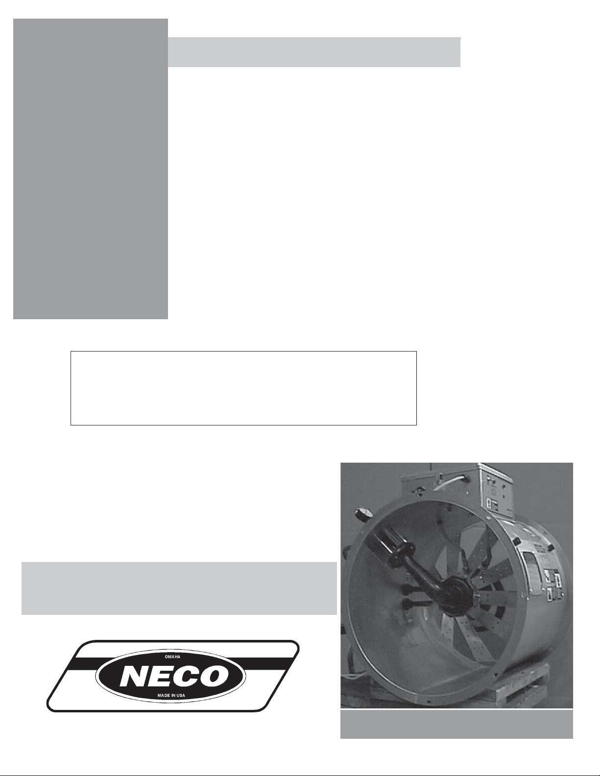
Deluxe Vane Axial Heater
Vane Axial Heater
Deluxe
MODEL # VH __ - __ __ - __ __ - D (HIGH FIRE)
MODEL # VL __ - __ __ - __ __ - D (LOW FIRE)
Owner's
Manual
MANUAL # PNEG-816
1
Page 2

VANE AXIAL HEATER CHECK LIST
!OK
_____ 1. All wire connections
_____ 2. Spark plug gap .125
_____ 3. Pipe train tightness and gas leaks
_____ 4. Flame sensor tight
_____ 5. Fuse in place, extra fuse provided
_____ 6. Time delay reset
_____ 7. Indicator light
_____ 8. Pressure gauge
Deluxe Vane Axial Heater
_____ 9. Regulator adjusted
_____ 10. Shut off valve operates correctly
_____ 11. Vapor high limit
_____ 12. Unit cycles on to off
_____ 13. Heat rise even across transition
_____ 14. Unit cycles hi to lo (hi-lo only)
_____ 15. Mod valve holds temperature within 1 degree
(mod units only).
_____ 16. All decals and serial number tag
_____ 17. Aesthetic appearance
_____ 18. Manual
Tester Signature___________________________________
Date_________________________
2
Page 3

Deluxe Vane Axial Heater
Roof Warning, Operation & Safety..........................................................................4
Safety Alert Decals..................................................................................................6
Standard Vane Axial Heater Installation................................................................10
Fuel Connection...............................................................................................10
Heater Electrical Installation............................................................................11
Plenum Thermostat Mounting.........................................................................12
Transition Hi-Limit Installation.......................................................................12
Second Heater Installation...............................................................................13
Temperature Heater Specifications.................................................................14
Standard Vane Axial Heater Operation..................................................................15
Standard Heater Operation...............................................................................15
Hi-Lo Heater Operation...................................................................................15
BTU's Per Gauge Pressure (PSI) Propane Models (Approximate)..................16
BTU's Per Gauge Pressure (PSI) Natural Gas Models (Approximate)............17
Adjusting The Vaporizor..................................................................................18
Modulating Valve Operation............................................................................19
Wiring Schematic...................................................................................................20
Heater Parts............................................................................................................21
18" Gas Heater..................................................................................................21
24" & 26" Gas Heater.......................................................................................22
28" Gas Heater..................................................................................................23
Control Box......................................................................................................24
Axial Propane Vapor Pipetrain.........................................................................25
Axial Natural Gas Pipetrain.............................................................................26
Axial Propane Vapor Hi-Lo Pipetrain..............................................................27
Axial Natural Gas Hi-Lo Pipetrain...................................................................28
Axial LP Pipetrain.................................................................................................29
Warranty..................................................................................................................27
TABLE OF CONTENTS
3
Page 4
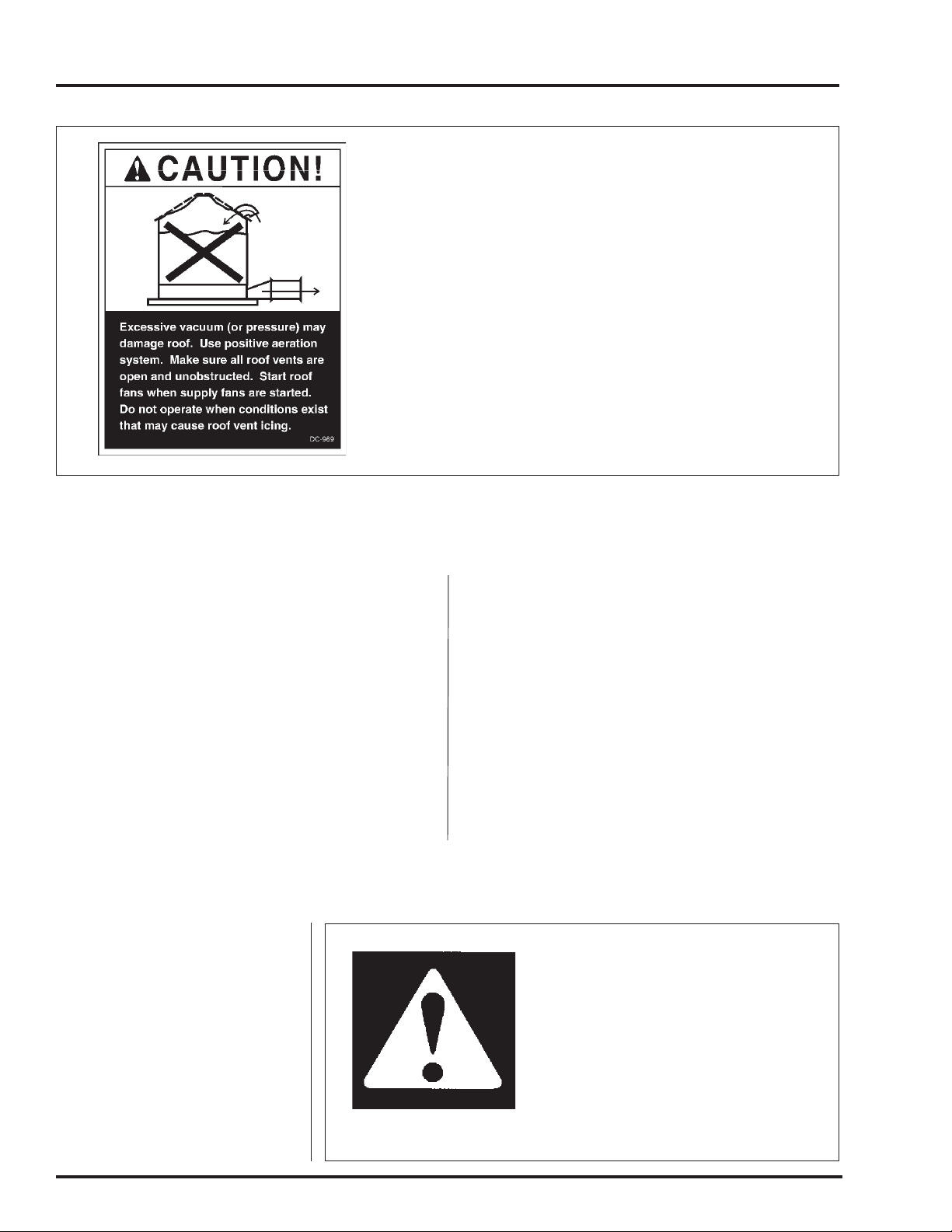
WARNING AND DISCLAIMER
NECO DOES NOT WARRANT ANY ROOF DAMAGE
CAUSED BY EXCESSIVE VACUUM OR INTERNAL
PRESSURE FROM F ANS OR OTHER AIR MOVING SYSTEMS. ADEQUATE VENTILATION AND/OR "MAKEUP
AIR" DEVICES SHOULD BE PROVIDED FOR ALL POWERED AIR HANDLING SYSTEMS. NECO DOES NOT
RECOMMEND THE USE OF DOWNWARD FLOW SYSTEMS (SUCTION). SEVERE ROOF DAMAGE CAN RESUL T FROM ANY BLOCKAGE OF AIR P ASSAGES. RUNNING FANS DURING HIGH HUMIDITY/COLD
WEATHER CONDITIONS CAN CAUSE AIR EXHAUST
OR INTAKE PORTS TO FREEZE.
Deluxe Vane Axial Heater
Heater Operation
Thank you for choosing a NECO product. It is
designed to give excellent performance and service for many years.
This manual describes the operation of the
NECO Deluxe Vane Axial Heater. Many models
are available to accommodate low, medium or
high temperature grain conditioning.
The principal concern of Neco is your safety
and the safety of others associated with grain handling equipment. This manual is written to help you
understand safe operating
Safety Alert Symbol
The symbol shown is used to call
your attention to instructions concerning your personal safety.
Watch for this symbol; it points
out important safety precautions.
It means "ATTENTION",
"W ARNING", "CAUTION", and
"DANGER". Read the message
and be cautious to the possibility
of personal injury or death.
procedures, and some of the problems that may be
encountered by the operator or other personnel.
As owner and/or operator, it is your responsibility to know what requirements, hazards and
precautions exist, and to inform all personnel associated with the equipment, or who are in the
heater area. Avoid any alterations to the equipment. Such alterations may produce a very dangerous situation, where serious injury or death
may occur.
Warning! Be Alert!
Personnel operating or working
around electric fans should read this
manual. This manual must be
delivered with the equipment to its
owner. Failure to read this manual
and its safety instructions is a misuse
of the equipment.
4
Page 5

Deluxe Vane Axial Heater
WARNING AND DISCLAIMER
Fuel Warning
Important! Do not use propane tanks which have previously been
used for ammonia unless they have been purged according to procedures of the National L. P. Association.
Be sure fuel supply system complies with all local codes for
L.P Gas installations. DO NOT USE FLAME FOR LEAK TEST-
ING.
Power Warning
Be sure power is disconnected and locked out before installation! Failure to do so may cause
serious injury or death.
Important! Heater must be interlocked with fan for safe operation.
Important! Thermostat must be installed for safe operation.
Proper Use of Product
This product is intended for the use of grain drying only! Any other use is a misuse of this
product.
This product has sharp edges! These sharp edges may cause serious injury. To avoid injury
5
Page 6
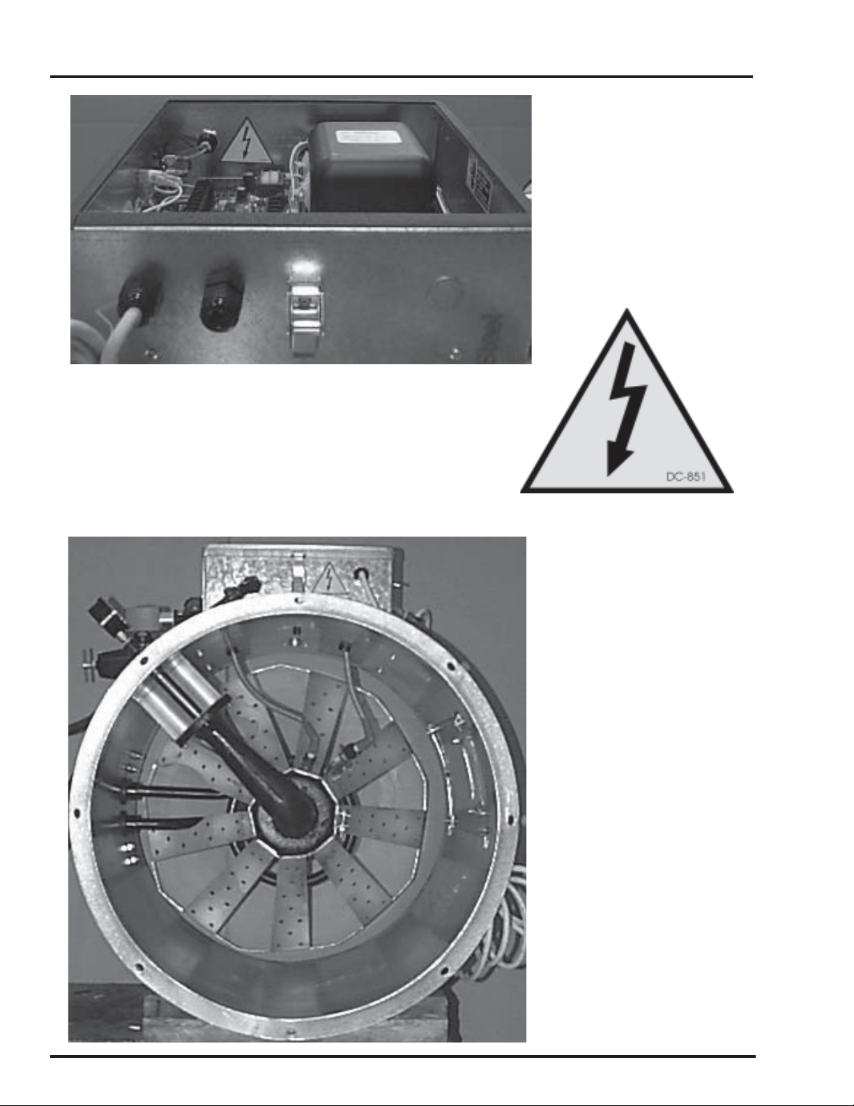
SAFETY ALERT DECALS
Neco recommends contacting your local power company, and
having a representative survey your installation so the wiring is
compatible with their system, and adequate power is supplied to
your unit.
Deluxe Vane Axial Heater
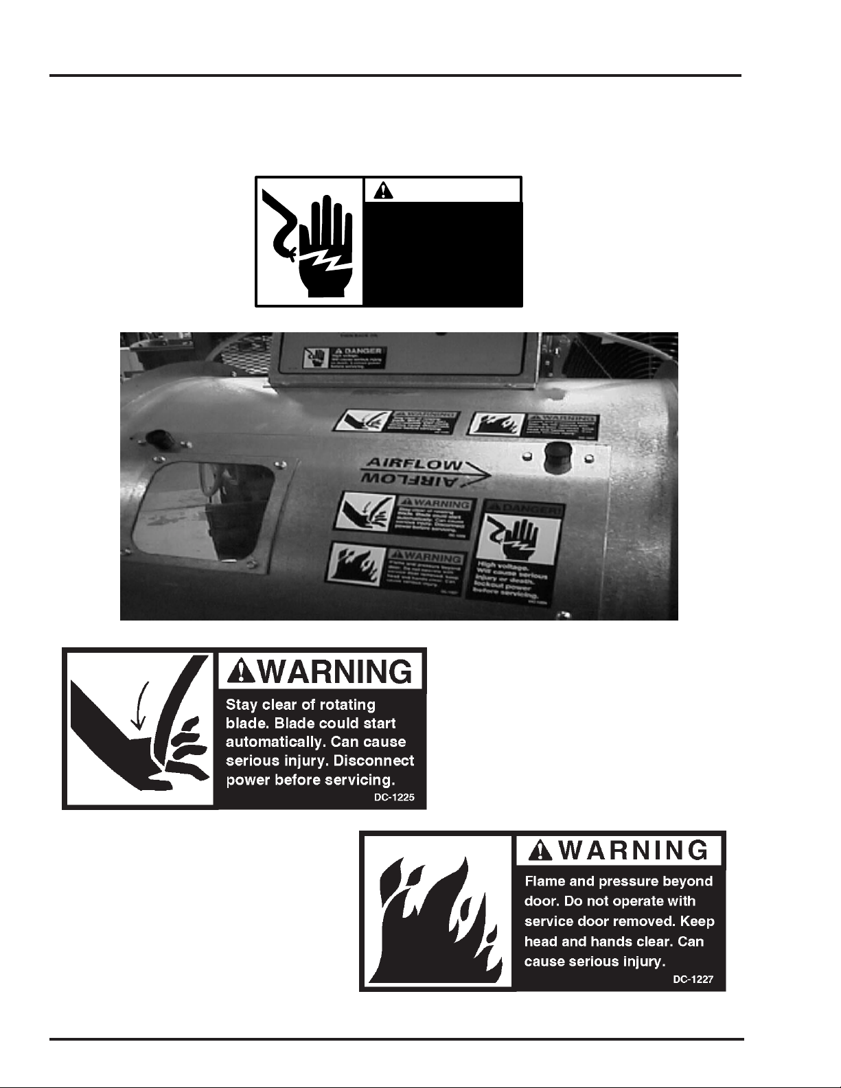
Safety decals should be
read and understood by all
people in the grain handling
area. The bottom-right decal
warns that the enclosure contains electrical devices carrying high voltages that will
cause injury or death. Lockout
power before servicing.
If a decal is damaged or is
missing contact:
Neco
Box 12277, 9364 N. 45 St.
Omaha, Nebraska 68112
402-453-6912
A free replacement will be sent
to you.
6
Page 7
Deluxe Vane Axial Heater
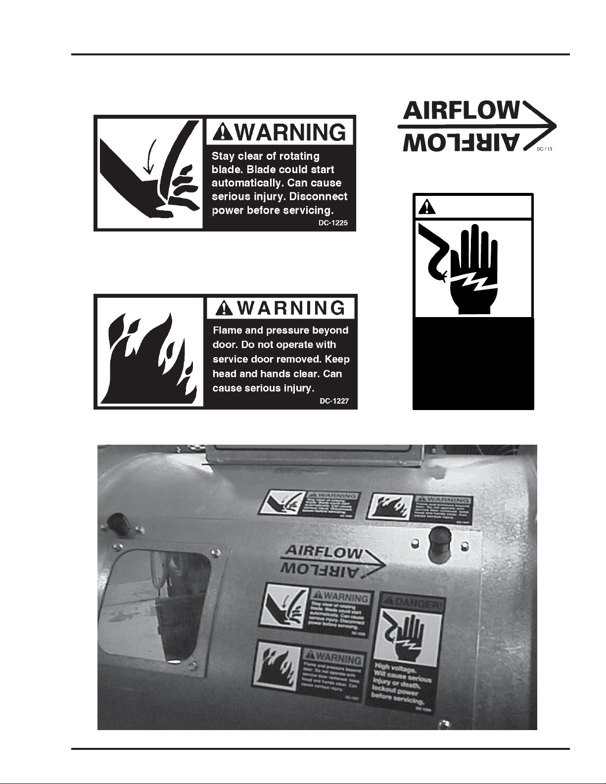
SAFETY ALERT DECALS
Safety Alert Decals for Door
DANGER!
High voltage.
Will cause serious
injury or death.
Lockout power
before servicing.
DC-1224
7
Page 8
SAFETY ALERT DECALS
Deluxe Vane Axial Heater
Safety Decals for Bin
DANGER!
High voltage.
Will cause injury
or death.
Lockout power
before servicing.
DC-889
8
Page 9
Deluxe Vane Axial Heater
WARMER COLDER
VAPORIZER ADJUSTMENT
VAPORIZER COIL SHOULD BE ADJUSTED
SO VAPOR PIPE TRAIN IS WARM
(100-125 DEGREES F) TO THE TOUCH
SAFETY ALERT DECALS
DC-535
DANGER!
High voltage.
Will cause injury
or death.
Lockout power
before servicing.
DC-889
9
Page 10
HEATER INSTALLATION
Important! Do not use propane tanks which have previously been used for ammonia unless they have been purged
according to procedures of the National L. P . Association.
Be sure fuel supply system complies with all local codes
for L. P. gas installations. DO NOT USE FLAME FOR
LEAK TESTING.
Deluxe Vane Axial Heater
Fuel Connection
Liquid Propane Models
1. LP models are designed to run on liquid propane, with liquid draw from the propane tank.
A void using propane supply tanks that have been
used for vapor draw for long periods of time.
When using liquid draw systems any moisture
that may be present in tank or lines may freeze
when system is used in cold weather. To avoid
this, the usual precaution is to purge the system
with methanol.
2. Run proper size line (see specifications on page
14) to liquid pipe train on heater. Have a qualified gas service man inspect installation to be
sure that everything is installed according to local codes and ordinances.
3. After installation is complete check all connections for leaks with liquid detergent or comparable. Wear rubber gloves and eye protection.
Avoid contact with liquid propane. DO NOT
USE FLAME FOR LEAK TESTING.
2. Run proper size line (see specifications on page
14) to pipetrain on heater . Have a qualified gas
service person inspect installation to be sure everything is installed according to local codes and
ordinances.
3. After installation is complete check all connections for leaks. DO NOT USE FLAME FOR
LEAK TESTING.
Natural Gas Models
1. Natural gas models are similar to vapor mod-
els, but have a larger orifice to accommodate
lower pressure sometimes found with natural gas.
2. Run proper size line (see specifications on page
14) to pipetrain on heater . Have a qualified gas
service man inspect installation to be sure everything is installed according to local codes and
ordinances.
Propane Vapor Models
1. Propane vapor models are designed to run directly off of supply tank or from a separate external vaporizer.
10
3. After installation is complete check all connections for leaks. DO NOT USE FLAME FOR
LEAK TESTING.
Page 11
Deluxe Vane Axial Heater
Heater Electrical Installation (230V Fans)
THESE INSTRUCTIONS ARE
FOR HEATER INSTALLATION
ON FAN UNITS WITH 230V
MOTORS.
BE SURE POWER IS
DISCONNECTED AND
LOCKED OUT BEFORE
INSTALLATION!
FAILURE TO DO SO MAY
CAUSE SERIOUS INJURY
OR DEATH.
HEATER INSTALLATION
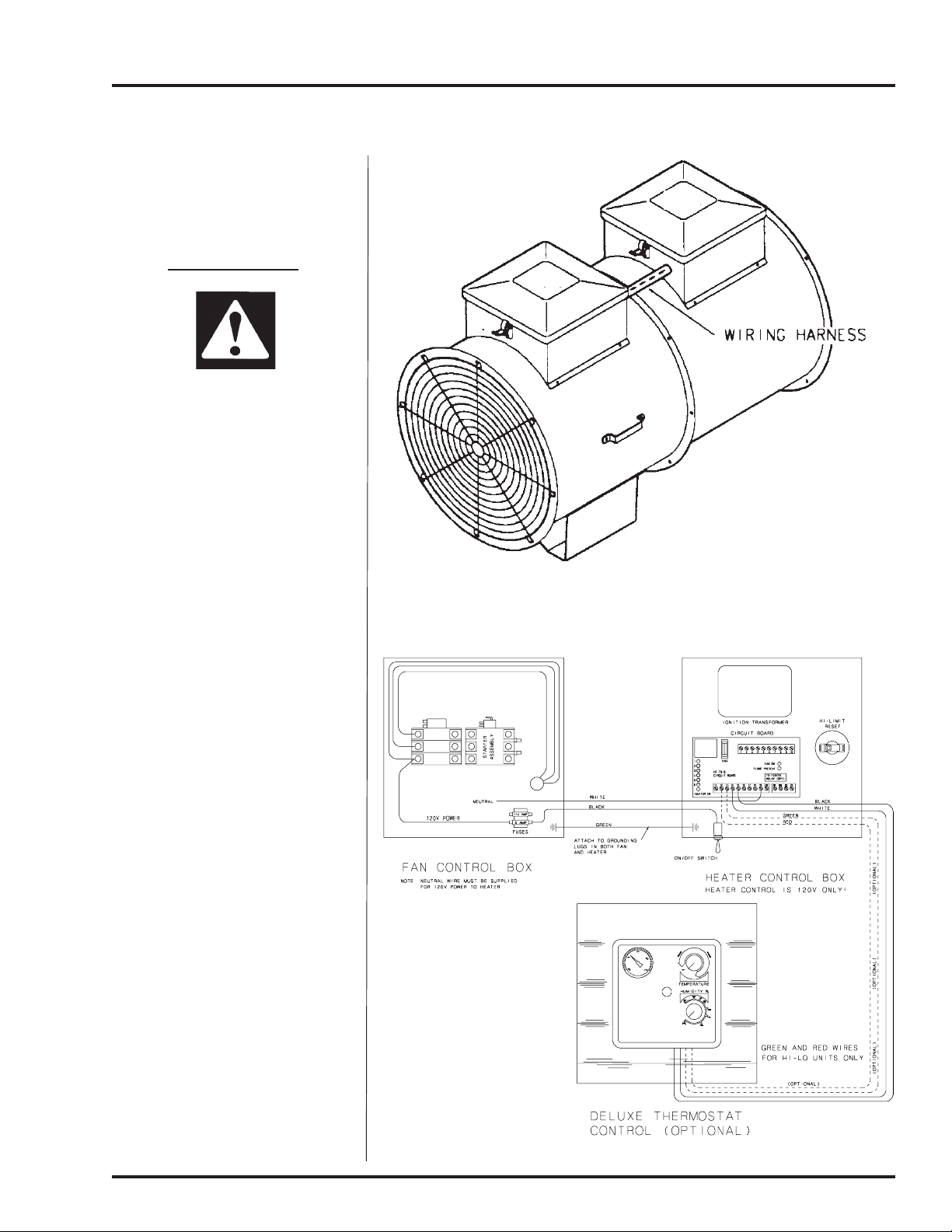
1. Connect power cord to fan
control box.
2. Make field connection of
wires in fan box as shown in
Figure 2. 110V power supply
or .5KVA 460V to 110V
transformer must be used to
supply power for heater. IM
POR T ANT! HEA TER MUST
BE INTERLOCKED WITH
F AN FOR SAFE
OPERATION.
3. Connect deluxe thermostat
control (optional) as shown in
Figure 2. IMPORTANT!
THERMOSTAT MUST BE
INSTALLED FOR SAFE
OPERATION.
Figure 1: Illustration of deluxe vane axial heater wiring installation
on a fan unit.
Figure 2: Deluxe vane axial heater wiring to fan unit.
11
Page 12
HEATER INSTALLATION
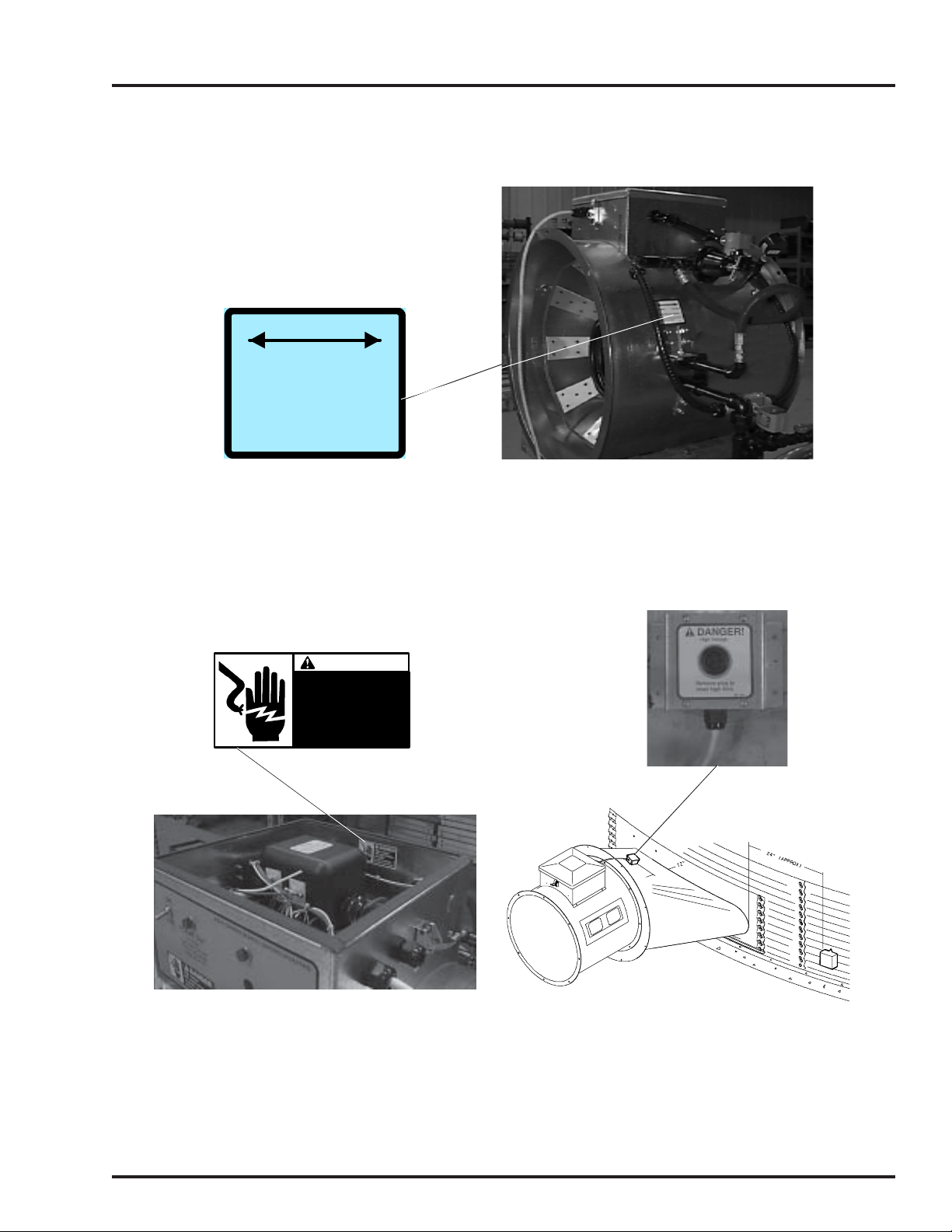
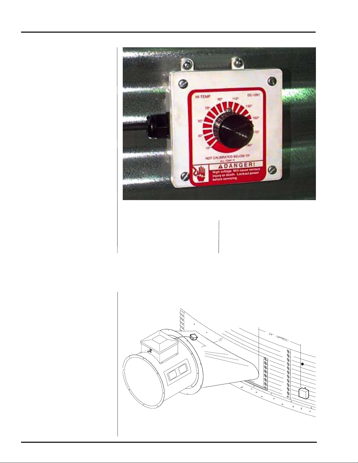
Plenum Thermostat
Mounting
The plenum thermostat is the 4 x
4 white box with knob that is
preconnected to heater when
heater is ordered with thermostat.
1. 24" to the right side of the
transition, drill one 3/8" hole
(high temp) or 1 1/2" hole (low
temp) in the center of the plenum in a valley (4.00" corrugation) or hill (2.66" corrugation) on bin sidewall.
2. Insert the probe through the
hole.
Deluxe Vane Axial Heater
Plenum thermostat mounting on bin wall.
3. Position the housing so that
the tabs are vertical, and the
cord exits the housing horizontally.
1. Mark location on transition
one (1) foot up from the bottom (entrance collar) and centered in the transition.
2. Drill or knock out 7/8" diameter hole on marked
location.
3. Install transition hi-limit using supplied self drilling
screws.
4. Use 4 self drilling screws to
5. Caulk between the housing
mount the housing to the bin
sidewall.
Transition Hi-Limit Installation
and the sidewall to seal.
12
Figure 2: The transition connecting the Vane Axial Heater to the bin with
the plenum sensor in place.
Page 13
Deluxe Vane Axial Heater
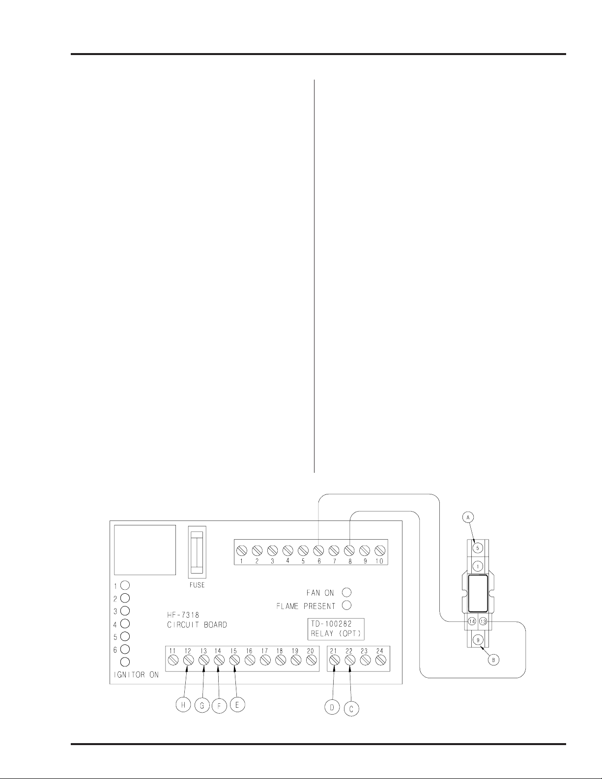
SECOND HEATER INSTALLATION
For Units Using
HF-7318 Control Board
2 Deluxe heaters may be connected to one grain
drying system and wired so they cycle together.
One of the heaters should have a thermostat
connected to it as per the installation instructions.
That heater will be referred to as the master. The
other heater (without the thermostat) will be
referred to as the slave.
Installation For
Standard Units
1. Install relay base (TD-100283) in master
heater control box.
2. Connect wire between term 6 on circuit board
and terminals 14 on relay base in master
heater.
3. Connect wire between term 13 on relay base
and terminals 8 on circuit board in master
heater.
4. Run 2 wires (18 gage) between master and
slave heaters.
5. Connect wires to terminal 5 and 9 (points A
and B) on relay base in master heater.
6. Connect wire from terminal 9 in master to
terminal 14 (point F) in slave unit.
7. Connect wire from terminal 5 in master to
terminal 15 (point E) in slae unit.
8. Install relay (TD-100282) in relay base.
Additional Steps For
Hi-Lo Units
1. Run 2 wires (18 gage) between master and slave
unit.
2. Connect wires to terminals 21 and 22 (points C
and D) on circuit board in main heater.
3. Connect wire from terminal 21 in master to
terminal 12 (point H) in slave unit.
4. Connect wire from terminal 22 in master to
terminal 13 (point G) in slave unit.
5. Install relay (TD-100282) in relay base.
Figure 4: The HF-7318 control board.
13
Page 14

HEATER INSTALLATION
High Temperature Heater Specifications
Deluxe Vane Axial Heater
All models
Liquid models
Vapor models
Natural gas
models
Inside diameter
Bolt circle diameter
Length
BTU rating
Weight
Maximum fuel flow (GPH)
Orifice
Modulating valve bypass orifice
Minimum operating pressure
Maximum operating pressure
Minimum line size
Maximum fuel flow (CFH)
Orifice
Modulating valve bypass orifice
Minimum operating pressure
Maximum operating pressure
Minimum line size
Maximum fuel flow (CFH)
Orifice
Modulating valve bypass orifice
Minimum operating pressure
Maximum operating pressure
Minimum line size
18"
18.5/16"
19.7/16"
22"
1400000
81
N/A
N/A
N/A
N/A
N/A
N/A
585
5/32"
Green
2
20
1/2"
1473
1/4"
Blue
1
7
3/4"
24"
24.1/4"
25.3/4"
22.1/2"
2100000
110
23
3/16"
Blue
2
20
3/8"
877
3/16"
Blue
2
20
3/4"
2210
5/16"
Aluminum
1
7
1"
26"
26.5/16"
27.15/16"
22.1/4"
2700000
115
30
7/32"
Blue
2
20
3/8"
1128
7/32"
Blue
2
20
3/4"
2842
23/64"
Aluminum
1
7
1.1/4"
28"
28.1/8"
29.5/8"
25.1/4"
3000000
140
34
15/64"
Aluminum
2
20
3/8"
1253
15/64"
Aluminum
2
20
3/4"
3157
3/8"
Aluminum
1
7
1.1/4"
All models
Vapor models
Natural gas
models
Low Temperature Heater Specifications
18"
Inside diameter
Bolt circle diameter
Length
BTU rating
Weight
Maximum fuel flow (GPH)
Orifice
Modulating valve bypass orifice
Minimum operating pressure
Maximum operating pressure
Minimum line size
Maximum fuel flow (CFH)
Orifice
Modulating valve bypass orifice
Minimum operating pressure
Maximum operating pressure
Minimum line size
18.5/16"
19.7/16"
22"
400000
81
167
5/64"
Red
2
20
3/8"
421
9/64"
Yellow
1
7
1/2"
24.1/4"
25.3/4"
22.1/2"
500000
3/32"
Yellow
5/32"
Green
24"
110
292
2
20
3/8"
736
1
7
1/2"
26"
26.5/16"
27.15/16"
22.1/4"
500000
115
292
3/32"
Yellow
2
20
3/8"
736
5/32"
Green
1
7
1/2"
28"
28.1/8"
29.5/8"
25.1/4"
500000
140
292
3/32"
Yellow
2
20
3/8"
736
5/32"
Green
1
7
1/2"
14
Page 15

Deluxe Vane Axial Heater
HEATER OPERATION
Standard Heater
Operation
1. Thermostat must be wired into heater control
box for heater to operate.
2. Open all manual shutoff valves to heater unit.
3. Start fan. This will supply power to heater.
4. Turn thermostat dial to itshighest setting.
5. Turn toggle switch on.
6. Heater should now be lit. If not check to see
that all gas is on.
7. Watch thermometer on plenum and when it
reaches desired temperature turn thermostat
back slowly until heater cycles off.
Hi-Lo Heater
Operation
1. Hi-limit and cycling thermostat must be wired
into heater control box for heater to operate.
2. Open all manual shutoff valves to heater unit.
3. Start fan. This will supply power to heater.
4. Turn thermostat dial to itshighest setting.
5. Turn toggle switch on. Both red lights should
light up indicating power to the control circuit.
6. Heater should now be lit. If not check to see
that all gas is on.
7. Open low-fire ball valve all the way.
8. Gas pressure should be adjusted so burner is
on 75% of the time.
9. Watch plenum temperature as burner goes
through a few cycles, to be sure that it is operating properly.
8. Turn thermostat dial back slowly until heater
cycles to low flame.
9. Adjust ball valve so that low-flame pressure is
at desired setting.
10. Turn thermostat dial to desired setting and wait
for bin plenum to come up to temperature.
Heater should cycle to low flame after a few
minutes. If heater does not cycle to
low flame increase hi-flame gas pressure.
11. Low-flame should be adjusted so that temperature drops slowly until burner goes back to high
flame.
12. Watch as burner goes through a few cycles, to
be sure that it is operating properly .back to high
flame.
15
Page 16

HEATER OPERATION
BTU's Per Gauge Pressure (PSI) Propane Models (Approximate)
Deluxe Vane Axial Heater
High Temperature
Operating Pressure (PSI)
Diameter
18"
24"
26"
28"
Diameter
18"
24-28"
Fan Model
3HP-18"
7HP-24"
10HP-24"
15HP-26"
15HP-28"
2
416380
598250
816010
935660
4
588680
844730
1148640
1318540
6
720290
1036170
1409480
1617670
8
832760
1198890
1632030
1868930
10
930880
1340080
1825860
2091480
12
1019420
1464520
1995762
2309250
14
1107800
1581770
2153700
2467180
16
1174960
1689460
2302070
2649050
18
1244360
1787570
2436070
2792630
Low Temperature
Operating Pressure (PSI)
2
102900
148370
4
145970
210580
6
181870
258440
8
208190
299130
10
234510
335020
12
253660
366130
14
275200
394850
16
294340
421170
18
311090
447490
Gauge Pressure (PSI) Required to Maintain Temperature (Approximate)
(High Temp Units Only)
Static
Pressure
1"
2"
3"
1"
2"
3"
4"
1"
2"
3"
4"
1"
2"
3"
4"
5"
1"
2"
3"
4"
5"
60
2
1
low-temp
2
1
low-temp
low-temp
4
3
2
1
2
2
1
1
low-temp
3
2
2
1
low-temp
80
3
1
low-temp
4
3
low-temp
low-temp
6
5
3
2
4
4
3
3
1
4
4
3
2
1
Heat Rise Degrees F
100
4
2
1
6
4
1
low-temp
9
8
4
3
6
5
4
4
2
7
6
4
3
2
120
5
3
2
8
5
2
low-temp
13
10
6
4
8
7
5
5
3
9
8
5
4
3
140
6
4
2
10
7
3
1
18
14
8
5
11
9
7
7
3
12
11
8
6
3
160
8
5
3
14
9
3
2
22
18
9
6
14
13
10
9
4
16
14
10
8
4
20
1340080
1892860
2577260
2955360
20
335020
473810
180
9
6
3
17
11
4
3
26
22
11
8
18
16
13
11
5
20
18
13
10
5
16
Page 17

Deluxe Vane Axial Heater
BTU's Per Gauge Pressure (PSI) Natural Gas Models (Approximate)
HEATER OPERATION
High Temperature
Operating Pressure (PSI)
Diameter
18"
24"
26"
28"
Diameter
18"
24-28"
Gauge Pressure (PSI) Required to Maintain Temperature (Approximate)
Fan Model
3HP-18"
7HP-24"
10HP-24"
15HP-26"
15HP-28"
1
454180
710450
938450
1022350
1
144100
177840
Static
Pressure
1"
2"
3"
1"
2"
3"
4"
1"
2"
3"
4"
1"
2"
3"
4"
5"
1"
2"
3"
4"
5"
644780
1006850
1331520
1450080
205200
251710
60
1
1
low-temp
1
1
low-temp
low-temp
2
1
1
low-temp
1
1
1
1
low-temp
1
1
1
1
low-temp
2
2
3
787970
1231200
1627920
1772020
4
909260
1419980
1876896
2043790
Low Temperature
Operating Pressure (PSI)
3
250800
308260
(High Temp Units Only)
80
1
1
low-temp
2
1
low-temp
low-temp
2
2
1
1
2
1
1
1
low-temp
2
2
1
1
low-temp
100
2
1
1
2
1
1
low-temp
4
3
1
1
2
2
2
1
1
3
2
2
1
1
4
289100
355680
Heat Rise Degrees F
120
2
1
1
3
2
1
1
5
3
2
1
3
3
2
1
1
4
3
2
1
1
5
1016880
1587790
2099420
2285470
5
322850
397632
140
3
2
1
4
2
1
1
6
4
2
1
4
3
3
2
1
5
4
3
2
1
6
1115380
1741920
2302800
2507090
6
353860
435936
160
3
2
1
5
3
1
1
7
6
3
2
5
4
3
2
1
7
5
4
2
2
7
1204750
1881456
2487940
2708640
7
383040
470590
180
4
3
31
6
4
2
1
8
7
4
2
7
5
4
3
2
8
6
5
3
2
17
Page 18

HEATER OPERATION
Deluxe Vane Axial Heater
Adjusting the
Vaporizor
1. Vaporizer should be adjusted
so the vapor pipetrain runs
warm to the touch (100°120°F).
2. Loosen 5/16" bolt on adjustment bracket.
3. Swivel vaporizer away from
flame if running too hot,
closer to flame if too cold.
4. Move vaporizer only 1" at a
time and allow a few minutes
for temperature to equalize.
5. Tighten 5/16" bolt and watch
heater run for several minutes
to verify adjustment.
Adjusting the vaporizer coil on a liquid propane model. The top photo
shows the setting in, and the bottom photo shows the coil out.
18
Page 19

Deluxe Vane Axial Heater
LTD HEATER OPERA-
TION
Modulating Valve Operation
Your LTD heater is equipped with a modulating
valve. The following material should be read
thoroughly.
1. The modulating valve regulates gas flow through
the heater based on sensing unit in the plenum,
and maintains a constant drying air temperature.
2. The sensing bulb of the modulating valve should
be mounted through the bin wall with the reading side top up. The bulb reacts to temperature.
It changes the amount of gas (increase or decrease), burning warmer or cooler depending on
the position of the valve SET POINT . If the bulb
is cooler than it was at the SET POINT , the bulb
senses the cooler temperature and opens the
valve further so more heat is applied to the drying air. If the bulb is warmer than it was at the
SET POINT , the valve closes further and reduces
the temperature until the air is at the valve SET
POINT.
3. It is important that the pressure regulator be set
high enough to allow the modulating valve to
deliver enough gas to maintain the plenum temperature necessary. The regulator is normally
factory set at 15 psi. T o set the regulator, run the
heater and turn the modulating valve T-handle
in. This gets full line pressure to the burner . Then
adjust regulator to read 15 psi (depending on
the plenum temperature needed).
4. Turn the fan and heater on. To set the modulating valve, turn the T-handle out (counterclockwise)
until loose and wait a few minutes for the plenum temperature to equalize. When the temperature under the bin has equalized, gradually turn
T-handle in (clockwise) about 1/2 turn. W ait
until temperature under bin has equalized as before.
If temperature under bin is less than the desired
temperature, continue turning T-handle in, increasing gas flow and waiting for plenum temperature to equalize until the desired temperature is the stable temperature of the plenum. If
temperature under bin is the same 10 minutes
after you last made any adjustments to the Thandle you can be certain that the temperature
under the bin is the SET POINT of the valve
turn of the T-handle equals approximately 7
degrees F of temperature.
5. The valve will now keep the plenum temperature at the set point regardless of ambient conditions as long as humidistat or thermostat do not
shut down the heater. A bypass orifice is used
to maintain a small flame when outside temperature is near or above the set point of the valve.
The bypass insures steady application of heat
at minimum gas flow operation.
6. The modulating valve may require minor adjustment periodically if a certain temperature rise
over ambient (outside) temperature is desired.
7. To observe how the modulating valve increases
the efficiency of bin drying, check the gas pressure of the unit in the morning and compare to
the pressure read mid-afternoon. If the ambient
(outside) temperature is significantly greater
later in the day (as normal), the gas pressure will
be less. Since less heat is required to maintain
the same temperature in the plenum, the modulating valve will have reduced the amount of
gas used by the heater. This is preferred to cycling the application of heat as is commonly done. The grain is not shocked
and cooled quickly and then reheated,
which is a waste of fuel in conventional bin drying systems.
. 1
19
Page 20

DELUXE HEATER WIRING DIAGRAM
Deluxe Vane Axial Heater
20
Page 21

Deluxe Vane Axial Heater
HEATER PARTS
21
Page 22

HEATER PARTS
r
r
r
A
Key Part NumberDescription
1 HF-6785 18" Heater Housi n g
2 HH-3933 18" Burner Ca sting
3 HH-1180 18" Flame Spre ad er
3 HH-4410 18" Lo-Temp Flame Spreade
4 HF-7078 18" Flame Divert e
4 HF-7073 18" Lo-Temp Flame Diverte
5 HF-6062-18 18" Access Panel (Deluxe, Sr 2000)
5 HF-7381-18 18" Access Panel (Standard)
6 HF-7380 Plastic View Window
7 HF-7379
8 TFH-2046 Access Panel Latch
9 HF-983 18/24" B urn er Col le ct or
10 HF-978 18/24/26" Burner Collector Plate
11 HH-4416 Drum Grill Guard (LTD)
12 HH-4421 Stand-Off Bracket (LTD)
13 F-953 18" Grill Guard (LTD)
14 HH-1 650 Spark Plug
NS HF-1810 Spark Plug Nut
NS HF-7260 18-28" Heater Spark Plug Wire
NS HF-7262 18-28" Heater Flame Prob e Wi re
15 *THH-4179 Flame Sensor (Deluxe, Sr 2000)
15 HH-1097 Flame Probe (Standard)
16 CD-0187 Flame Sensor Bracket (Deluxe, Sr 2000)
16 HF-4485 Flame Probe Bracket (Standard)
Deluxe Vane Axial Heater
18" Gas Heater
ccess Panel Cover Plate
22
Page 23

Deluxe Vane Axial Heater
HEATER PARTS
18" Gas Heater
*THH-4179 Flame
sensor will not work in
place of mechanical
probes (HH-1097 and
HH-3977). Use flame
sensor update kit
HF-7136.
23
Page 24

HEATER PARTS
A
Key Part Number Description
1 HF-6175 24" Heater Housing
1 HF-6176 26" Heater Housing
2 HH-3934 24/26" Burner Casting
3 HH-1179 24/26" Flame Spreader
3 HF-6757 24/26/28" Lo-Temp Flame Spreader
4 HF-7103 24/26" Flame Diverter
4 HF-7107 24/26/28" Lo-Temp Flame Diverter
4 HF-7104 24/26" Diverter Collar
5 HF-6062-24 24" Access Panel (Deluxe, Sr 2000)
5 HF-7381-24 24" Access Panel (Standard)
5 HF-6062-26 26" Access Panel (Deluxe, Sr 2000)
5 HF-7381-26 26" Access Panel (Standard)
6 HF-7380 Plastic View Window
7 HF-7379
8 TFH-2046 Access Panel Latch
9 HF-983 18/24" Burner Collector
9 HF-986 26" Burner Collector
10 HF-978 18/24/26" Burner Collector Plate
11 HH-7016 Rubber Grommet
12 HF-7056 Pivot Bracket
13 HF-7057 Adjustment Bracket
14 HF-7060 Vaporizer Support Weldment
15 THF-3237 Vaporizer Cover
16 HH-1650 Spark Plug
NS HF-1810 Spark Plug Nut
NS HF-7260 18-28" Heater Spark Plug Wire
NS HF-7262 18-28" Heater Flame Probe Wire
17 *THH-4179 Flame Sensor (Deluxe, Sr 2000)
17 HH-1097 Flame Probe (Standard)
18 CD-0187 Flame Sensor Bracket (Deluxe, Sr 2000)
18 HF-4485 Flame Probe Bracket (Standard)
19 HH-7054 24-28" Burner Cone
Deluxe Vane Axial Heater
24" & 26" Gas Heater
ccess Panel Cover Plate
24
Page 25

Deluxe Vane Axial Heater
HEATER PARTS
24" & 26" Gas Heater
*THH-4179 Flame
sensor will not work in
place of mechanical
probes (HH-1097 and
HH-3977). Use flame
sensor update kit
HF-7136.
25
Page 26

HEATER PARTS
A
A
Key Part Numbe r Descr ip tion
1 HF-6060 28" Heater Housing
2 H H- 39 34 24/26" Burner Casting
2 THF-3141 28" Burner Casting
3 THF-3144 28" Flame Spreader
3 HF-6757 24/26/28" Lo-Temp Flame Spreader
4 HF-7105 28" Flame Diverter
4 HF-7107 24/26/28" Lo-Temp Flame Diverter
4 HF-7106 28" Diverter Collar
4 H F- 71 04 24/26" Diver ter Collar
5 HF-6062-28 28" Access Panel (Deluxe, Sr 2000)
5 HF-7381-28 28" Access Panel (Standard)
6 HF-7380 Plastic View Window
7 HF-7379
8TFH-2046
9 THF-3101 28" Burner Collector
9 HF-986 26" Burner Collector
10 HF-7 092 28 " Burner Collector Plate
10 HF-978 18/24/26" Burner Collector Plate
11 HH-7016 Rubber Grommet
12 HF-7056 Pivot Bracket
13 HF-7057 Adjustment Bracke t
14 HF-7060 Vaporizer Support Weldment
15 THF-3237 Vaporizer Cover
16 HH-1650 Spark Plug
NS HF-1810 Spark Plug Nut
NS HF-7260 18-28" Heater Spark Plug Wire
NS HF- 72 62 18-28" Heater Flam e Pro be Wi r e
17 *THH-4179 Flame Sensor (Deluxe , Sr 2000 )
17 HH-1097 Flame Probe (Standard)
18 CD-0187 Flame Sensor Bracket (Deluxe, Sr 2000)
18 HF-4485 Flame Probe Bracket (Standard)
19 HH- 70 54 24-28" Bur ner Con e
Deluxe Vane Axial Heater
28" Gas Heater
ccess Panel Cover Plate
ccess Panel Latch
26
Page 27

Deluxe Vane Axial Heater
HEATER PARTS
28" Gas Heater
*THH-4179 Flame
sensor will not work in
place of mechanical
probes (HH-1097 and
HH-3977). Use flame
sensor update kit
HF-7136.
27
Page 28

g
y
g
gg
g
g
g
g
y
HEATER PARTS
KeyPart Number Description
1 F-942 Control Box Lid
2 HH-1487 I
3 HF-7318 Circuit Board Assembl
4 HH-1092 High Limit Switch 180 Degree
5 FH-4429-1 Sprin
6 HH-7015 Snap trak
7 HF-7046 18" Control B ox Housi ng
7 HF-7047 24" Control B ox Housi ng
7 HF-7098 26" Control B ox Housi ng
7 HF-7051 28" Control B ox Housi ng
8 DC-1166 Decal Deluxe Heater Front Pa nel
9 TFH-2021 Red Light (110V)
10 HH-1442 To
11 HF-7455 Hi
12 HF-7439 Hi
13 HF-7454 Hi
14 HF-7414 Recess ed Plastic Plu
15 TD-100282 Optional Rela
15 FH-1310 Cord Connector
Deluxe Vane Axial Heater
Control Box Parts
niton Tr an sfo r m er
Latch
le Switch
h Limit Switch Box Bottom
h Limit Switch 250 Degree
h Limit Switch Box Top
28
Page 29

Deluxe Vane Axial Heater
HEATER PARTS
Control Box Parts
*When replacing a pre1993 HF-7100 circuit
board assembly (1)
HF-7203 relay is
required.
29
Page 30

HEATER PARTS
Key Part Number Description
1 TFC-0023 1/2" 0-30 PSI Regulator (Deluxe, Sr 2000)
1 HH-1077 1/2" 0-30 PSI Regulator (Standard)
2 HH-3670 1/2" x 2 1/2" Nipple
3 TFC-0032 1/2" Solenoid (Deluxe, Sr 2000)
3 HH-1081 1/2" Solenoid (Standard)
4 HH-2029 1/2" x 1 1/2" Nipple
5 HH-2984 30 PSI gauge
6 S-3853 1/2" x 1/4" x 1/2" Tee
7 HH-1083 18/24/28" Orifice Pipe
7 HH-1107 26" Orifice Pipe
8 HF-7036 5/32" Orifice Plug (18" Standard)
8 CD-0149 5/64" Orifice Plug (18" Lo-Temp)
8 HF-7086 3/16" Orifice Plug (24" Standard)
8 HF-7084 3/32" Orifice Plug (24/26/28" Lo-Temp)
8 HF-7087 7/32" Orifice Plug (26" Standard)
8 HF-7088 15/64" Orifice Plug (28" Standard)
9 HH-2653 Modulating Valve (Optional)
10 HH-1251 1/2" Strainer
Deluxe Vane Axial Heater
Axial Propane Vapor Pipetrain
30
Page 31

Deluxe Vane Axial Heater
HEATER PARTS
Axial Propane Vapor Pipetrain
31
Page 32

HEATER PARTS
Key Part NumberDescription
1 TFC-0051 3/4" Ball Valve
2 THH-4136 3/4" x 3" Nipple
3 TFC-0081 3/4" Sol enoid (D eluxe, Sr 2000)
3 THH -4039 3/4 " S olenoid ( Standard)
4 THH -4121 3/4 " Close Ni pple
5 THH -4158 3/4 " x 1/4" x 3 /4" Tee
6 D08 -0022 15 PSI G auge
7 HH-7026 3/4" 18/24/2 8 " Orifice Pipe
7 HH-7027 3/4" 26" Orifice Pipe
8 HF-7123 1/4" Orifice Plug (18" Standard)
8 HF-7124 5/16" O rifice Plug (24" Standard)
8 HF-7125 23/64 " Orifice (26" Standar d)
8 HF-7126 3/8" O rifice (28" Standard)
9 D67 -0008 3/4" Strainer
10 HH-7064 3/4" Modulating Valve (Optional)
Deluxe Vane Axial Heater
Axial Natural Gas Pipetrain
32
Page 33

Deluxe Vane Axial Heater
HEATER PARTS
Axial Natural Gas Pipetrain
33
Page 34

HEATER PARTS
g
)
)
(
)
gaug
g (
)
)
KeyPart Number Description
1 TFC-0023 1/2" 0-30 PSI Re
1 HH-1077 1/2" 0-30 PSI Regulator (Standard
2 HH-3670 1/2" x 2 1/2" Nipple
3 TFC-0032 1/2" Solenoid (Deluxe, Sr 2000)
3 HH-1081 1/2" Sole noid
4 HH-2029 1/2" x 1 1/2" Nipple
5 HH-1453 1/2" x 1/2" x 1/2" Tee
6 THH-4067 1/2" Street Elbow
7 TFC-0030 1/2" Ball Valve
8 S-3853 1/2" x 1/4" x 1/2" Tee
9 HH -2984 30 PSI
10 HH-7019 1/2" Gas Hose
11 HH-1107 26" Orifice Pipe
11 HH-1083 18/24/28" Orifice Pipe
12 HF-7036 5/32" Orifice Plug (18" Standard)
12 HF-7086 3/16" Orifice Plug (24" Standard)
12 HF-7087 7/32" Orifice Plu
12 HF-7088 15/64" Orifice Plug (28" Standard
13 HH-1251 1/2" Strainer
Deluxe Vane Axial Heater
Axial Propane Vapor Hi-Lo Pipetrain
ulator (Deluxe, Sr 2000
Standard
e
26" Standard
34
Page 35

Deluxe Vane Axial Heater
Axial Propane Vapor Hi-Lo Pipetrain
HEATER PARTS
35
Page 36

HEATER PARTS
r
Key Part NumberDescription
1 TFC-0051 3/4" Ball Valve
2 THH-4136 3/4" x 3" Nipple
3 TFC-0081 3/4" Solenoid (Deluxe, Sr 20 00)
3 THH-4039 3/4" Solenoid (Standard)
4 THH-4121 3/4" Cl ose Nipple
5 THH-4174 3/4 " x 3/4" x 1/2" Tee
6 THH-4067 1/2" Street Elbow
7 TFC-0030 1/2" Ball Valve
8 S-3853 1/2" x 1/4" x 1/2" Tee
9 D08-0022 15 PSI Gauge
10 H H-7019 1/2" Gas Hos e
11 H H-7026 3/4" 18/24/28" Orifice Pipe
11 H H-7027 3/4" 26" Orifice Pi pe
12 HF-7123 1/4" Orifice Plug (18" Standard)
12 HF-7124 5/16" Orifice Plug (24" Standard)
12 HF-7125 23/64" Orif ice (26" Standard)
12 HF-7126 3/8" Orifice (28" Standard)
13 D18-0002 3/4" x 1/2" x 3/4" Tee
14 H H-3670 1/2" x 2 1/2" Ni pple
15 D67-0008 3/4" Straine
Deluxe Vane Axial Heater
Axial Natural Gas Hi-Lo Pipetrain
36
Page 37

Deluxe Vane Axial Heater
Axial Natural Gas Hi-Lo Pipetrain
HEATER PARTS
37
Page 38

HEATER PARTS
Key Part Number Description
1 HH-4845 1/4" Relief Valve
2 THH-4058 1/2" x 1/2" x 1/ 2" Tee Sh. 80
3 THH-4089 1/2" Male Union El bow Sh. 80
4 THH-4071 1/2" El bow Sh. 80
5 CD-0198 Vaporizer Coil
6 D67-0005 1/2" Coupling
7 D07-0009 5/16" x 24" LP Gas Hose
8 HH-7013 200 Degree Vapor High Limit
9 D07-0019 1/2" x 1 1/2" Nipple Sh. 80
10 TFC-0092 1/2" Solenoid Valve 300 P SI
11 TFC-0030 1/2" Ball Valve
12 HH-1251 1/2" Strainer
13 THH-4023 1/2" x 1/4" R educer Bushing
Deluxe Vane Axial Heater
Axial LP Pipetrain
38
Page 39

Deluxe Vane Axial Heater
HEATER PARTS
Axial LP Pipetrain
39
Page 40

NOTES
______________________________________________________________________________________________________________
_____________________________________________________________________________________________________
__________________________________________________________________________________________________________
______________________________________________________________________________________________________
______________________________________________________________________________________________________
____________________________________________________________________________________________________________
_________________________________________________________________________________________________________________
_______________________________________________________________________________________________________________
______________________________________________________________________________________________________________
_____________________________________________________________________________________________________
__________________________________________________________________________________________________________
______________________________________________________________________________________________________
Deluxe Vane Axial Heater
______________________________________________________________________________________________________
____________________________________________________________________________________________________________
_________________________________________________________________________________________________________________
_______________________________________________________________________________________________________________
______________________________________________________________________________________________________________
_____________________________________________________________________________________________________
__________________________________________________________________________________________________________
______________________________________________________________________________________________________
______________________________________________________________________________________________________
____________________________________________________________________________________________________________
_________________________________________________________________________________________________________________
_______________________________________________________________________________________________________________
__________________________________________________________________________________________________________
40
Page 41

Deluxe Vane Axial Heater
NECO WARRANTS ALL PRODUCTS MANUFACTURED BY NECO TO BE FREE OF DEFECTS IN
MATERIAL AND WORKMANSHIP UNDER NORMAL USAGE AND CONDITIONS FOR A PERIOD
OF 12 MONTHS AFTER RET AIL SALE TO THE ORIGINAL END USER OF SUCH PRODUCTS. NECO'S
ONLY OBLIGATION IS, AND PURCHASER'S SOLE REMEDY SHALL BE FOR NECO, TO REPAIR
OR REPLACE, AT NECO'S OPTION AND EXPENSE, PRODUCTS THAT, IN NECO'S SOLE JUDGMENT, CONTAIN A MATERIAL DEFECT DUE TO MATERIALS OR WORKMANSHIP. ALL DELIVERY AND SHIPMENT CHARGES TO AND FROM NECO'S FACTORY WILL BE PURCHASER'S RESPONSIBILITY. EXPENSES INCURRED BY OR ON BEHALF OF THE PURCHASER WITHOUT PRIOR
WRITTEN AUTHORIZA TION FROM AN AUTHORIZED EMPLOYEE OF NECO SHALL BE THE SOLE
RESPONSIBILITY OF THE PURCHASER.
EXCEPT FOR THE ABOVE STATED EXPRESS LIMITED WARRANTIES, NECO MAKES NO WARRANTY OF ANY KIND, EXPRESSED OR IMPLIED, INCLUDING, WITHOUT LIMITATION, WARRANTIES OF MERCHANTABILITY OR FITNESS FOR A PARTICULAR PURPOSE OR USE IN CONNECTION WITH (i) PRODUCT MANUFACTURED OR SOLD BY NECO OR (ii) ANY ADVICE, INSTRUCTION, RECOMMENDA TION OR SUGGESTION PROVIDED BY AN AGENT , REPRESENT A TIVE
OR EMPLOYEE OF NECO REGARDING OR RELA TED T O THE CONFIGURATION, INSTALLATION,
LA YOUT , SUIT ABILITY FOR A P AR TICULAR PURPOSE, OR DESIGN OF SUCH PRODUCT OR PRODUCTS.
IN NO EVENT SHALL NECO BE LIABLE FOR ANY DIRECT, INDIRECT , INCIDENT AL OR CONSEQUENTIAL DAMAGES, INCLUDING, WITHOUT LIMITATION, LOSS OF ANTICIPATED PROFITS OR BENEFITS. PURCHASER'S SOLE AND EXCLUSIVE REMEDY SHALL BE LIMITED TO THAT
STATED ABOVE, WHICH SHALL NOT EXCEED THE AMOUNT PAID FOR THE PRODUCT PURCHASED. THIS WARRANTY IS NOT TRANSFERABLE AND APPLIES ONLY TO THE ORIGINAL
PURCHASER. NECO SHALL HAVE NO OBLIGATION OR RESPONSIBILITY FOR ANY REPRESENTATIVE OR WARRANTIES MADE BY OR ON BEHALF OF ANY DEALER, AGENT OR DISTRIBUTOR OF NECO.
NECO ASSUMES NO RESPONSIBILITY FOR FIELD MODIFICATIONS OR ERECTION DEFECTS
WHICH CREATE STRUCTURAL OR STORAGE QUALITY PROBLEMS. MODIFICATIONS TO THE
PRODUCT NOT SPECIFICALLY COVERED BY THE CONTENTS OF THIS MANUAL WILL NULLIFY ANY PRODUCT WARRANTY THAT MIGHT HAVE BEEN OTHERWISE AVAILABLE.
THE FOREGOING W ARRANTY SHALL NOT COVER PRODUCTS OR P AR TS WHICH HAVE BEEN
DAMAGED BY NEGLIGENT USE, MISUSE, ALTERATION OR ACCIDENT. THIS WARRANTY COVERS ONLY PRODUCTS MANUFACTURED BY NECO. THIS WARRANTY IS EXCLUSIVE AND IN
LIEU OF ALL OTHER WARRANTIES EXPRESS OR IMPLIED. NECO RESERVES THE RIGHT TO
MAKE DESIGN OR SPECIFICATION CHANGES AT ANY TIME.
PRIOR TO INST ALLATION, PURCHASER HAS THE RESPONSIBILITY TO RESEARCH AND COMPLY WITH ALL FEDERAL, STATE AND LOCAL CODES WHICH MAY APPLY TO THE LOCATION
AND INST ALLATION.
WARRANTY
41
Page 42

Deluxe Vane Axial Heater
42
Neco
Box 12277, 9364 North
45th Street
Omaha, Nebraska 68112
December 1998
 Loading...