

Page 1

PNEG-805
36' Diameter 40°/45° NCHT
Commercial Hopper Tanks
Installation Manual
PNEG-805
Date: 10-07-13
Page 2

All information, illustrations, photos and specifications in this manual are based on the latest
information available at the time of publication. The right is reserved to make changes at any
time without notice.
2PNEG-805 36' Diameter 40°/45° NCHT Commercial Hopper Tanks
Page 3

Table of Contents
Contents
Chapter 1 Introduction ..........................................................................................................................................5
Chapter 2 Safety .....................................................................................................................................................6
Safety Guidelines .................................................................................................................................. 6
Safety Instructions ..................... ... .... .......................................... ... ... ..................................................... 7
Safety Sign-Off Sheet ........................................................................................................................... 9
General Safety Statement ................................................................................................................... 10
Proper Storage of Grain Bin/Silo Materials Prior to Construction ....................................................... 11
Chapter 3 Decals ..................................................................................................................................................12
Chapter 4 Foundations ........................................................................................................................................16
36' Diameter Commercial Hopper Tank Foundation up to 18 Rings ................................................... 16
36' Diameter Commercial Hopper Tank Foundation 19-22 Rings ....................................................... 19
Chapter 5 Column Heights ..................................................................................................................................22
Standard Commercial Hopper Tank Column Heights ......................................................................... 22
Chapter 6 Substructure Part List ........................................................................................................................23
Substructure Part List for 36' Commercial Hopper Tanks ................................................................... 23
Typical NCHT36 Column .................................................................................................................... 24
Chapter 7 Hopper Section Assembly ................................ .................................................... .............................25
Hopper Section Assembly 36' Diameter Hopper Tanks ...................................................................... 25
Bracing Assembly ............................................................................................................................... 26
Install Compression Angle .................................................................................................................. 27
Install Compression Channel .............................................................................................................. 28
Install Hopper Panels .......................................................................................................................... 29
Tighten All Bolted Connections ........................................................................................................... 31
Install Rack and Pinion Roller Gate .................................................................................................... 32
Chapter 8 Sidewall Assembly .............................................................................................................................33
Sidewall Erection Instructions ... ... .......................................... .... ... ... ... ... .... ... ... ... ................................ 33
Caulking Detail .................................................................................................................................... 34
Decal Sheet Placement ....................................................................................................................... 35
Chapter 9 Lifting Jack .........................................................................................................................................36
Lifting Jack Usage .................................. ... ... .... ... ... ... .......................................... .... ... ... ...................... 36
Chapter 10 Color Code Charts ............................................................................................................................37
Color Code Chart 2.66" Commercial Stiffeners ........................ ......................................................... 37
Color Code Chart 2.66" Sidewall Gauges ......................................................................................... 37
Chapter 11 Hardware ...........................................................................................................................................38
Identifying Bolt Grades ...................................................................................................................... 38
Hardware Identification Notes ........................................................................................................... 39
Color Chart for Bin Hardware Bucket Lids ......................................................................................... 42
2.66" Commercial Tank Bolting Requirements - 2 Stiffeners per Sidewall Sheet ............................. 43
Chapter 12 Stiffeners ...........................................................................................................................................44
Universal Stiffener and Splice Hardware ..................... ................................................ ..................
Commercial Stiffeners for 2.66" Corrugation ..................................................................................... 45
2.66" Corrugation Commercial Stiffener Splice Details ..................................................................... 46
Non-Laminated Stiffener to Sidewall Detail ....................................................................................... 52
Laminated Stiffener to Sidewall Detail ......................................... ...................................................... 53
Universal Stiffener Starting Location - 2.66" Reverse Corrugation Outside Stiffener Only ............... 54
.... 44
PNEG-805 36' Diameter 40°/45° NCHT Commercial Hopper Tanks 3
Page 4

Table of Contents
Chapter 13 Roof Rafter Installation ....................................................................................................................55
Standard Roof Stiffener Detail - 2.66" Corrugation Outside Stiffener Only ....................................... 55
Special Roof Instructions for 36' Diameter Commercial Hopper Tank .............................................. 56
Chapter 14 Wind Ring ..........................................................................................................................................59
Wind Ring Assembly ......................................................................................................................... 59
Chapter 15 Base Stiffener ...................................................................................................................................60
Stiffener Shim Plate Detail (Use when Necessary) ........................................................................... 60
Chapter 16 Doors .................................................................................................................................................61
Access Door Weldment Assembly Hardware Package (PLS-41985) ................................................ 61
Chapter 17 Aeration .............................................................................................................................................62
Aeration Package (Optional) ............................................................................................................. 62
Chapter 18 Ladders .............................................................................................................................................66
Hopper Ladder Supports ................................................................................................................... 66
Chapter 19 Hoisting .............................................................................................................................................67
Hoist Instructions ............................................................................................................................... 67
Chapter 20 Flashing .............................................................................................................................................70
Flashing Installation ........................................................................................................................... 70
Chapter 21 Warranty ............................................................................................................................................73
4PNEG-805 36' Diameter 40°/45° NCHT Commercial Hopper Tanks
Page 5

1. Introduction
READ THIS MANUAL carefully to learn how to properly use and install equipment. Failure to do so could
result in personal injury or equipment damage.
INSPECT the shipment immediately upon arrival. The customer is responsible for ensuring that all
quantities are correct. The customer should report and note any damage or shortage on the bill of
lading to justify their claim to the transport company.
THIS MANUAL SHOULD BE CONSIDERED a permanent part of your equipment and should be easily
accessible when needed.
This warranty provides you the assurance that the company will back its products when defects appear
within the warranty period. In some circumstances, the company also provides field improvements, often
without charge to the customer, even if the product is out of warranty. Should the equipment be abused,
or modified to change its performance beyond the factory specifications, the warranty will become void
and field improvements may be denied.
PNEG-805 36' Diameter 40°/45° NCHT Commercial Hopper Tanks 5
Page 6
2. Safety
This is the safety alert symbol. It is used to alert you
to potential personal injury hazards. Obey all safety
messages that follow this symbol to avoid possible
injury or death.
WARNING indicates a hazardous situation which, if not
avoided, could result in death or serious injury.
CAUTION, used with the safety alert symbol, indicates a
hazardous situation which, if not avoided, could result in
minor or moderate injury.
NOTICE is used to address practices not related to
personal injury.
DANGER indicates a hazardous situation which, if not
avoided, will result in death or serious injury.
Safety Guidelines
This manual contains information that is important for you, the owner/operator, to know and understand.
This information relates to protecting personal safety and preventing equipment problems. It is the
responsibility of the owner/operator to inform anyone operating or working in the area of this equipment
of these safety guidelines. To help you recognize this information, we use the symbols that are defined
below. Please read the manual and pay attention to these sections. Failure to read this manual and its
safety instructions is a misuse of the equipment and may lead to serious injury or death.
DANGER
WARNING
CAUTION
NOTICE
6PNEG-805 36' Diameter 40°/45° NCHT Commercial Hopper Tanks
Page 7
2. Safety
Follow Safety Instructions
Carefully read all safety messages in this manual and
safety signs on your machine. Keep signs in good
condition. Replace missing or damaged safety signs. Be
sure new equipment components and repair parts include
the current safety signs. Replacement safety signs are
available from the manufacturer.
Learn how to operate the machine and how to use controls
properly. Do not let anyone operate without instruction.
Keep your machinery in proper working condition.
Unauthorized modifications to the machine may impair
the function and/or safety and affect machine life.
If you do not understand any part of this manual or need
assistance, contact your dealer.
Read and Understand Manual
Practice Safe Maintenance
Understand service procedures before doing work. Keep area
clean and dry.
Never lubricate, service, or adjust machine while it is in operation.
Keep hands, feet, and clothing away from rotating parts.
Keep all parts in good condition and properly installed. Fix
damage immediately . Replace worn or broken p arts. Remove any
built-up grease, oil, and debris.
Maintain Equipment
and Work Area
Safety Instructions
Our foremost concern is your safety and the safety of others associated with this equipment. We want to
keep you as a customer. This manual is to help you understand safe operating procedures and some
problems that may be encountered by the operator and other personnel.
As owner and/or operator, it is your responsibility to know what requirements, hazards, and precautions
exist, and to inform all personnel associated with the equipment or in the area. Safety precautions may be
required from the personnel. Avoid any alterations to the equipment. Such alterations may produce a very
dangerous situation where SERIOUS INJURY or DEATH may occur.
This equipment shall be installed in accordance with the current installation codes and applicable
regulations, which should be carefully followed in all cases. Authorities having jurisdiction should be
consulted before installations are made.
PNEG-805 36' Diameter 40°/45° NCHT Commercial Hopper Tanks 7
Page 8
2. Safety
Prepare for Emergencies
Be prepared if fire starts.
Keep a first aid kit and fire extinguisher handy.
Keep emergency numbers for doctors, ambulance service,
hospital, and fire department near your telephone.
Keep Emergency Equipment
Quickly Accessible
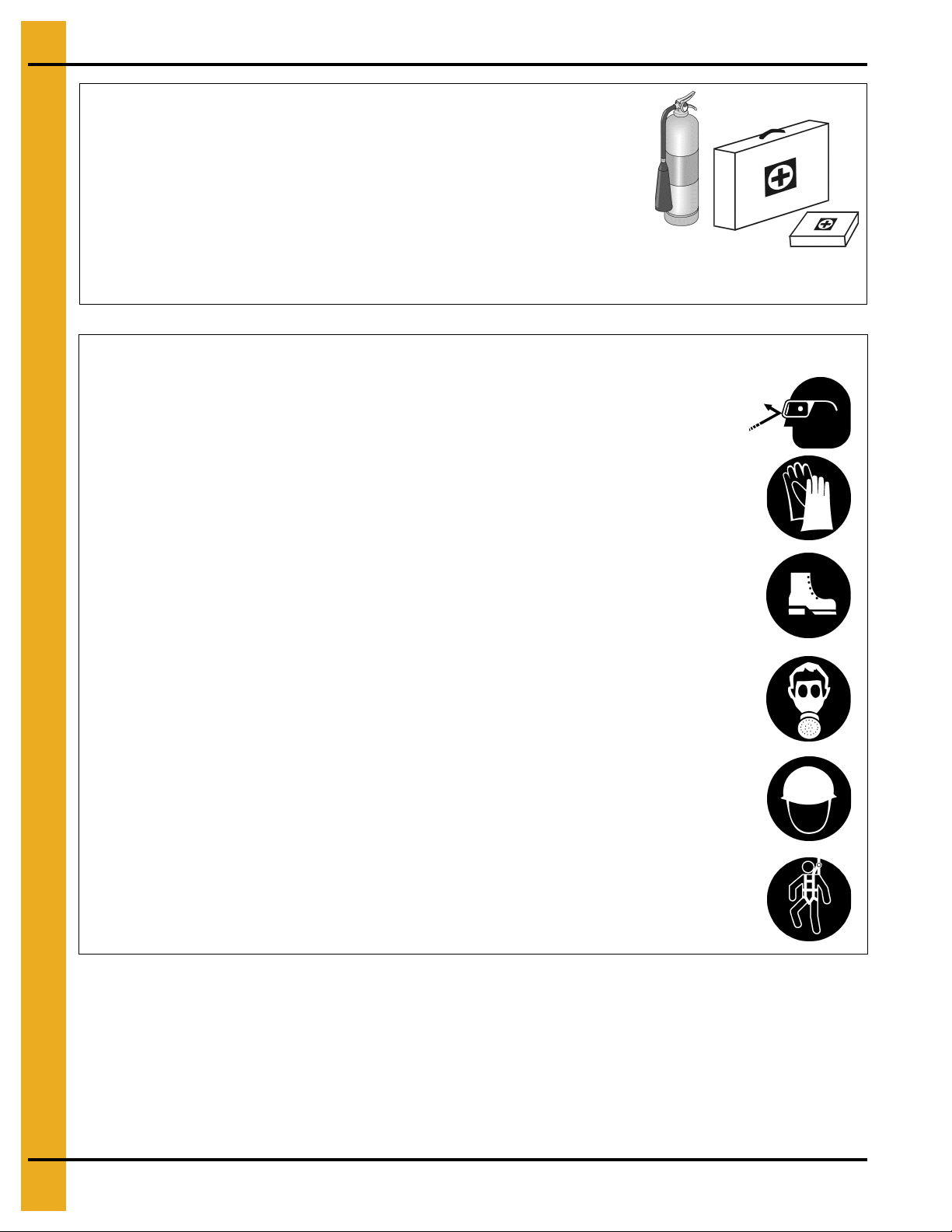
Wear Protective Clothing
Wear close-fitting clothing and safety equipment appropriate
to the job.
Remove all jewelry.
Tie long hair up and back.
Wear safety glasses at all times to protect eyes from debris.
Wear gloves to protect your hands from sharp edges on
plastic or steel parts.
Wear steel-toed boots to help protect your feet from falling
debris. Tuck in any loose or dangling shoestrings.
A respirator may be needed to prevent breathing potentially
toxic fumes and dust.
Wear a hard hat to help protect your head.
Wear appropriate fall protection equipment when working at
elevations greater than six feet (6').
Eye Protection
Gloves
Steel-Toed Boots
Respirator
Hard Hat
Fall Protection
8PNEG-805 36' Diameter 40°/45° NCHT Commercial Hopper Tanks
Page 9

2. Safety
Safety Sign-Off Sheet
As a requirement of O.S.H.A., it is necessary for the employer to train the employee in the safe operating
and safety procedures for this equipment. This sign-off sheet is provided for your convenience and
personal record keeping. All unqualified persons are to stay out of the work area at all times. It is strongly
recommended that another qualified person who knows the shut down procedure be in the area in the
event of an emergency.
Date Employee Name Supervisor Name
PNEG-805 36' Diameter 40°/45° NCHT Commercial Hopper Tanks 9
Page 10

2. Safety
This product has sharp edges, which may cause serious injury. To avoid injury, handle
sharp edges with caution and always use proper protective clothing and equipment.
General Safety Statement
Our foremost concern is your safety and the safety of others associated with grain handling equipment.
This manual is to help you understand safe operating procedures and some problems that may be
encountered by the operator and other personnel.
As owner and/or operator, you are responsible to know what requirements, hazards, and precau tions exist
and inform all personnel associated with the equipment or in the area. Safety precautions may be required
from the personnel. Avoid any alterations to the equipment, which may produce a very dangerous
situation, where SERIOUS INJURY or DEATH may occur.
You should consider the location of the bin site relative to power line locations or electrical transmission
equipment. Contact your local power company to review your installation plan or for information
concerning required equipment clearance. Clearance of portable equipment that may be taken to the bin
site should also be reviewed and considered. Any electrical control equipment in contact with the bin
should be properly grounded and installed in accordance with National Electric Code provisions and other
local or national codes.
This product is intended for the use of grain storage only. Any other use is a misuse of the product.
Sidewall bundles or sheets must be stored in a safe manner. The safest method of storing sidewall
bundles is laying horizontally with the arch of the sheet upward, like a dome. Sidewall sheets stored on
edge must be secured so that they cannot fall over and cause injury. Use care when handling and moving
sidewall bundles.
Personnel operating or working around equipment should read this manual. This manual must be
delivered with equipment to its owner. Failure to read this manual and its safety instructions is a
misuse of the equipment.
10 PNEG-805 36' Diameter 40°/45° NCHT Commercial Hopper Tanks
Page 11

2. Safety
Proper Storage of Grain Bin/Silo Materials Prior to Construction
Wet storage stain (rust) will develop when closely packed bundles of galvanized material, such as sidewall
and roof sheets, have moisture present. Inspect roof and sidewall bundles on arrival for any moisture.
If moisture is present, it must not be allowed to rema in between the sheets. Separate the sheets or panels
immediately and wipe them down. Spray with a light oil or diesel fuel.
If possible, sidewall bundles, roof sheets and other closely packed galvanized materials should be stored
in a dry, climate controlled building. If outdoor storage is unavoidable, the materials should be stored so
that they are raised above the ground and vegetation. Any stacking and spacing materials should not be
corrosive or wet. Be sure to protect materials from the weather, but permit air movement around the
bundles if possible.
Storing roof bundles and sidewall sheets at a slight incline can also help minimize the presence of
moisture. Storing the bundles with the center of the dome up (like an arch) is one option for minimizing
moisture during storage. Sidewall bundles can also be stored on edge but must be secured so that they
do not fall over and cause injury.
If “white rust” or “wet storage stain” occurs, contact the manufacturer immediately about ways to minimize
the adverse effect upon the galvanized coating.
PNEG-805 36' Diameter 40°/45° NCHT Commercial Hopper Tanks 11
Page 12
3. Decals
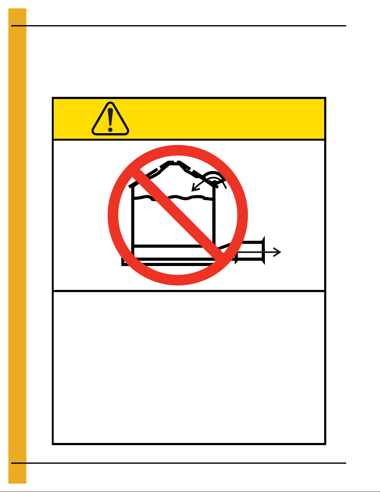
Excessive vacuum (or pressure) may
damage roof. Use positive aeration
system. Make sure all roof vents are
open and unobstructed. Start roof
fans when supply fans are started.
Do not operate when conditions exist
that may cause roof vent icing.
DC-969
CAUTION
GSI Group, Inc. 217-226-4421
The manufacturer does not warrant any roof damage caused by excessive vacuum or internal
pressure from fans or other air moving systems. Adequate ventilation and/or “makeup air” devices
should be provided for all powered air handling systems. The manufacturer does not reco mmend
the use of downward flow systems (suction). Severe roof damage can result from any block age of
air passages. Running fans during high humidity/cold weather conditions can cause air exhaust
or intake ports to freeze.
12 PNEG-805 36' Diameter 40°/45° NCHT Commercial Hopper Tanks
Page 13
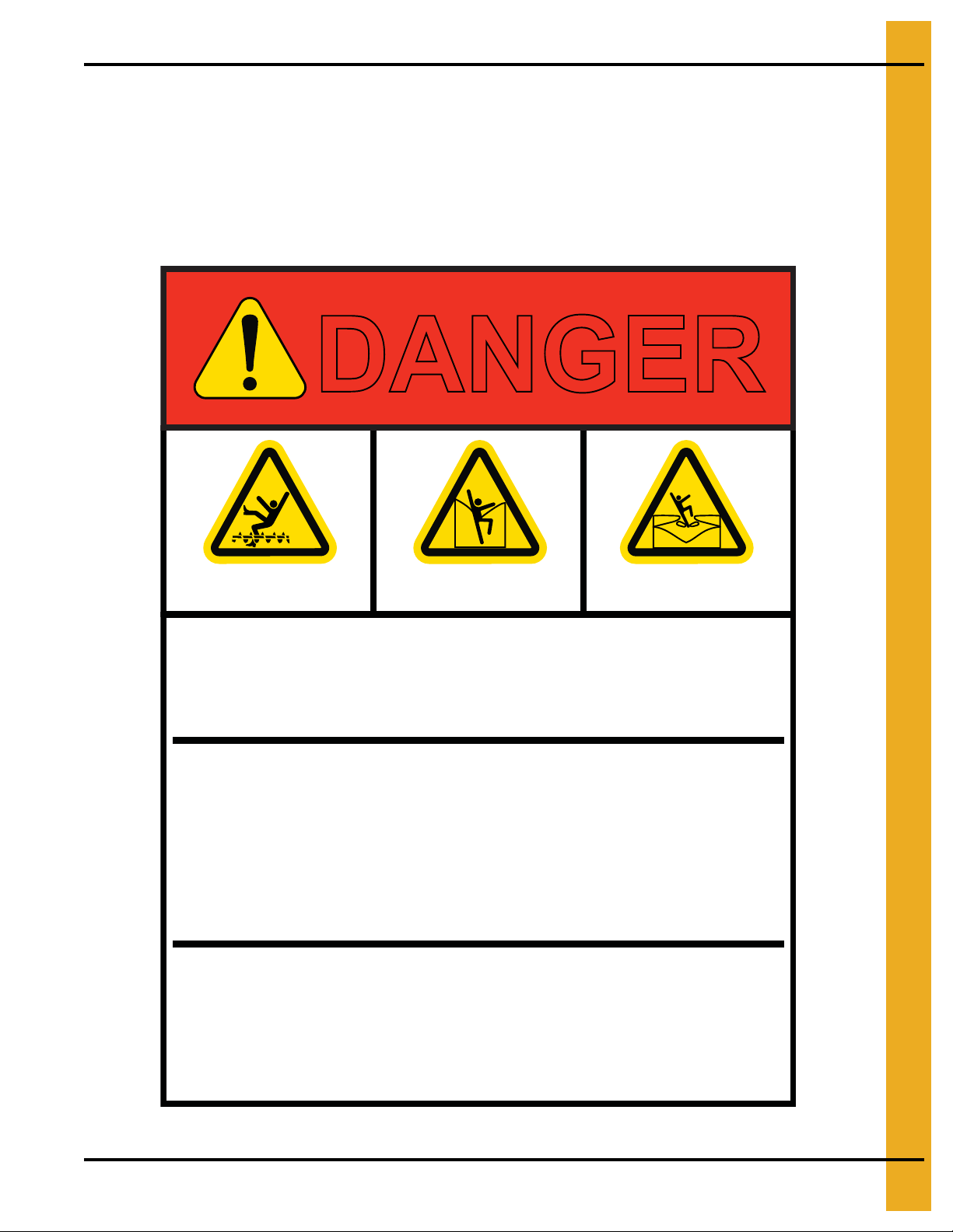
3. Decals
Rotating flighting will
kill or dismember.
Flowing material will
trap and suffocate.
Crusted material will
collapse and suffocate.
DANGER
Keep clear of all augers.
DO NOT ENTER this bin!
If you must enter the bin:
1. Shut off and lock out all power.
2. Use a safety harness and safety line.
3. Station another person outside the bin.
4. Avoid the center of the bin.
5. Wear proper breathing equipment or respirator.
Failure to heed these
warnings will result in
serious injury or death.
DC-GBC-1A
GSI GROUP, INC. 217-226-4421
ATTENTION: The decal shown below should be present on the outside of the door cover of the 2 ring,
24" porthole door cover and roof manway cover. If a decal has been damaged or is missing in any of these
locations, contact the manufacturer for a free replacement decal.
GSI Decals
1004 E. Illinois St.
Assumption, IL. 62510
Phone: 1-217-226-4421
PNEG-805 36' Diameter 40°/45° NCHT Commercial Hopper Tanks 13
Page 14
3. Decals
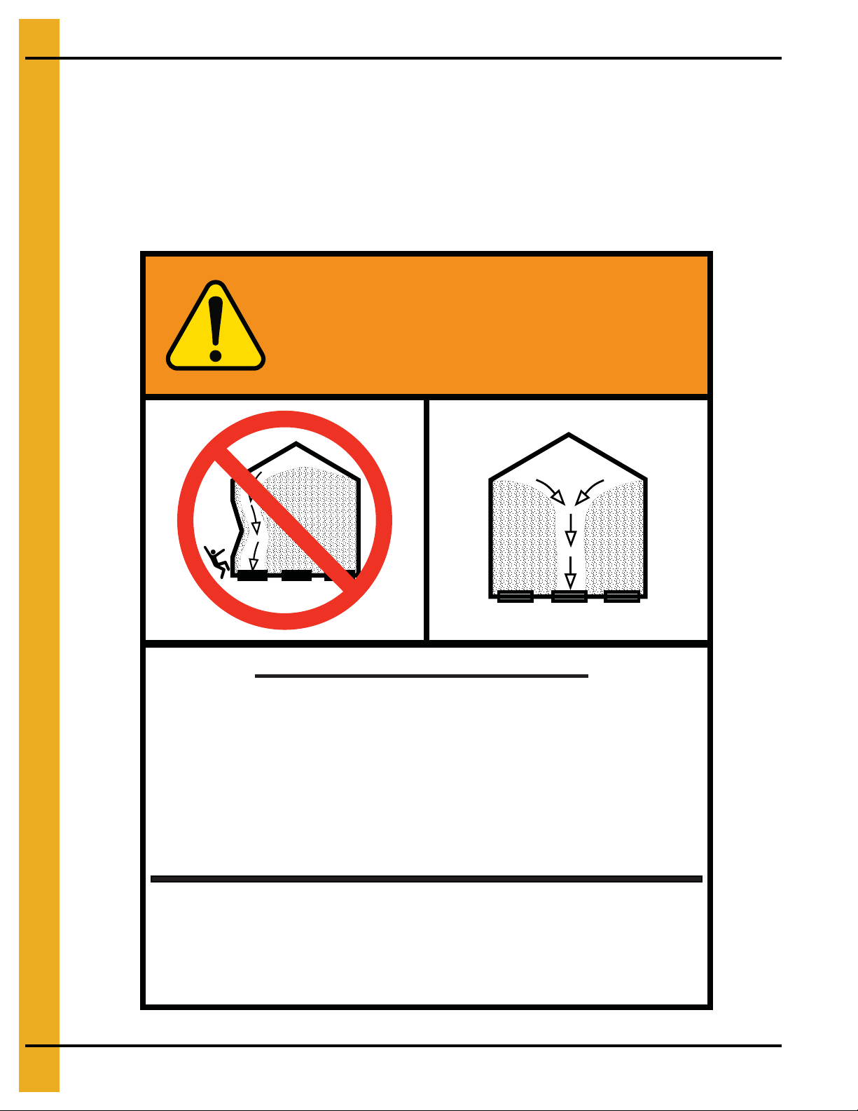
WARNING
GSI GROUP, INC. 217-226-4421
1. Use CENTER FLOOR OUTLET ONLY until NO grain
remains above this outlet.
2. Side floor outlets to be used ONLY when above
condition is satisfied.
3. Lock all side floor outlets to avoid accidental
premature use.
4. See manufacturers instructions for proper use of
factory supplied sidedraw (wall) discharge systems.
UNLOADING INSTRUCTIONS:
Failure to heed these warnings
could result in serious injury, death,
structural damage or collapse of tank.
DC-GBC-2A
ATTENTION: The decal shown below should be present on the outside of the door cover of the 2 ring,
24" porthole door cover and roof manway cover. If a decal has been damaged or is missing in any of these
locations, contact the manufacturer for a free replacement decal.
GSI Decals
1004 E. Illinois St.
Assumption, IL. 62510
Phone: 1-217-226-4421
14 PNEG-805 36' Diameter 40°/45° NCHT Commercial Hopper Tanks
Page 15

Sidewall and stiffener gauge sheets are
not included in this manual. They may
be obtained by calling GSI if they are
not attached to the front of this manual.
PNEG-805 36' Diameter 40°/45° NCHT Commercial Hopper Tanks 15
Page 16
4. Foundations
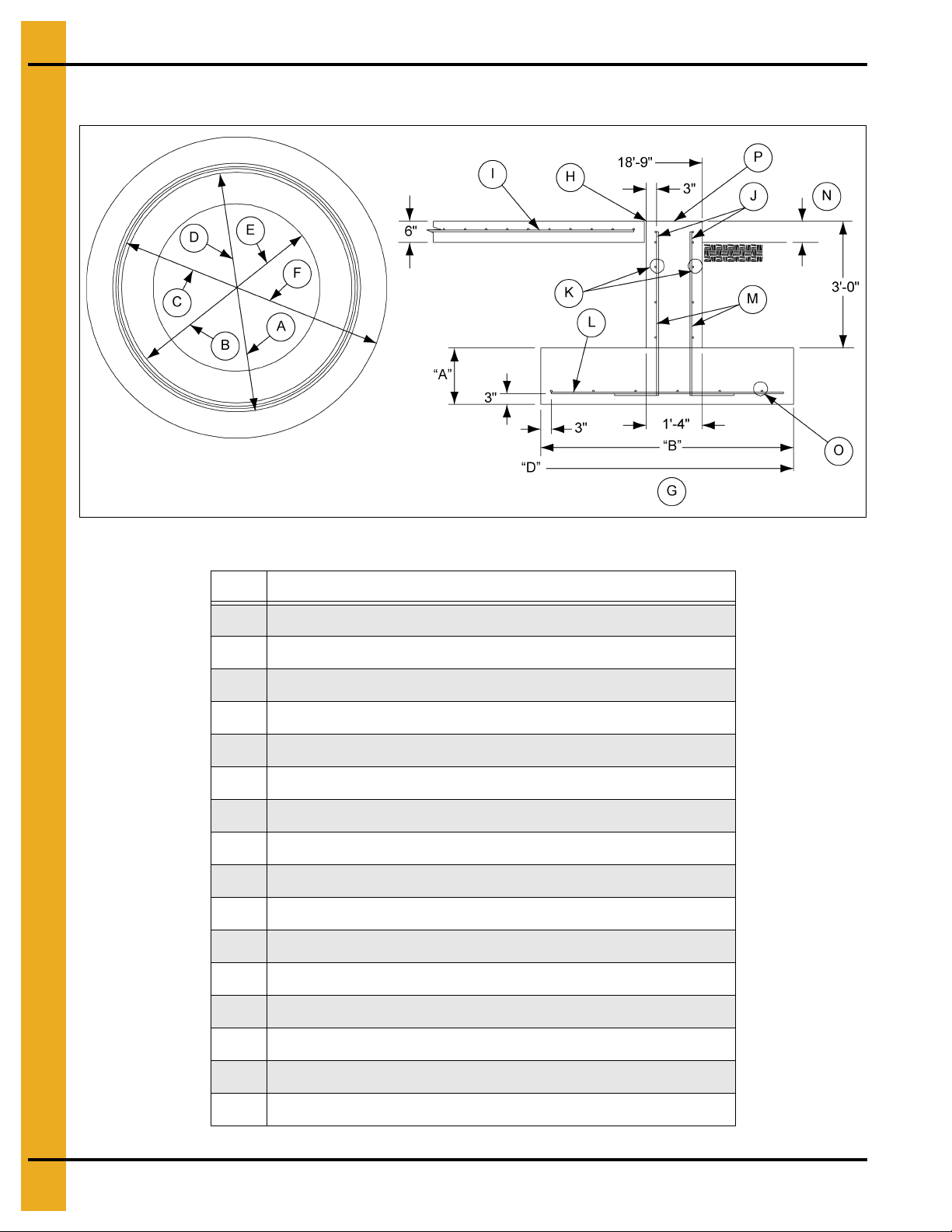
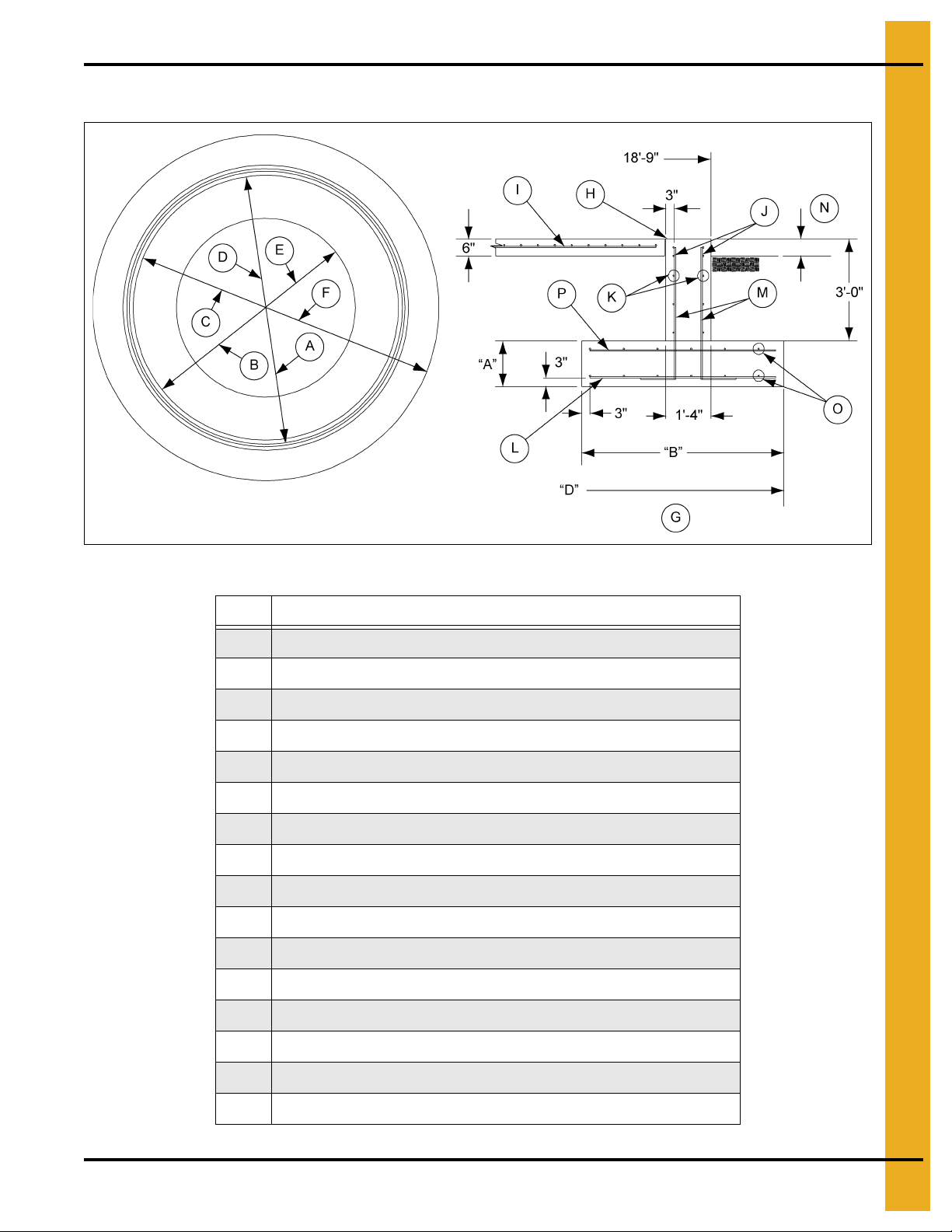
36' Diameter Commercial Hopper Tank Foundation up to 18 Rings
Figure 4A
Ref # Description
A 18'-9" Radius
B 18' - 2-5/8" Radius
C 17' - 10-5/8" Radius
D 17'-5" Radius
E “C” Radius
F “D” Radius
G Footing Detail (NOTE: Not to scale.)
H 1/2" Expansion Joint
I 6 x 6 - 6/6 Wire Mesh
J 1 Extra #4 Hoop at 3" c/c Each Face at Top
K 4-#4 Hoops Evenly Spaced Each Face
L “P” Bars Spacing at Center of Footing
M #4 Bars at 12" c/c Each Face with 12" Hook at Bottom
N 6" Maximum
O “N” #5 Hoops Evenly Spaced
P 1" Diameter Anchor Bolt 96 Required. (See section detail on Page 18.)
16 PNEG-805 36' Diameter 40°/45° NCHT Commercial Hopper Tanks
Page 17

4. Foundations
36' Diameter Commercial Hopper Tank Foundation up to
18 Rings (Continued)
# of Rings Up to 10 14 18
A 1'-4" 1'-4" 1'-8"
B 6'-0" 7'-6" 9'-2"
C 14'-11" 13'-11" 12'-11"
D 20'-11" 21'-5" 22'-1"
N #5 at 12" c/c #5 at 10" c/c #5 at 9" c/c
P #5 at 10" c/c #6 at 10" c/c #7 at 8-1/2" c/c
#4 Rebar (Ft.) 2400 2400 2400
#5 Rebar (Ft.) 1500 1000 1400
#6 Rebar (Ft.) 0 1000 0
#7 Rebar (Ft.) 0 0 1400
6 x 6 - 6/6 Wire Mesh (Ft.2)
Concrete (Cu. Yds.) 75 80 110
960 960 960
NOTES:
1. The foundation design is based on a minimum allowable soil bearing capacity of 3000 PSF.
Bearing capacity of the soils should be determined by geotechnical investigation and be of uniform
bearing capacity.
2. The foundation site must be free of vegetation and debris and well drained.
3. The foundation must be founded below the frost line or placed on non-expansive frost free fill.
4. All material used for backfill inside the ring wall should be clean, well graded, crushed rock or a
sand-gravel mixture. Backfill should be placed in 6" lifts, 95% compaction.
5. All reinforcement must meet the requirements of ASTM A615 grade 60 deformed bars.
6. Lap all circumferential bars 35 bar diameters and stagger all laps in plans 3'-0". Estimates for material
do not include end laps.
7. Concrete must have a minimum compressive strength of 3000 PSI at 28 days, 6%-8% air
entrainment, 4" slump.
8. Codes: UBC 97, ACI 318-95.
9. Interior top slab may be crowned 2" to provide water drainage away from foundation. Crowning the
slab will reduce the clearance under the discharge.
PNEG-805 36' Diameter 40°/45° NCHT Commercial Hopper Tanks 17
Page 18
4. Foundations
36' Diameter Commercial Hopper Tank Foundation up to
18 Rings (Continued)
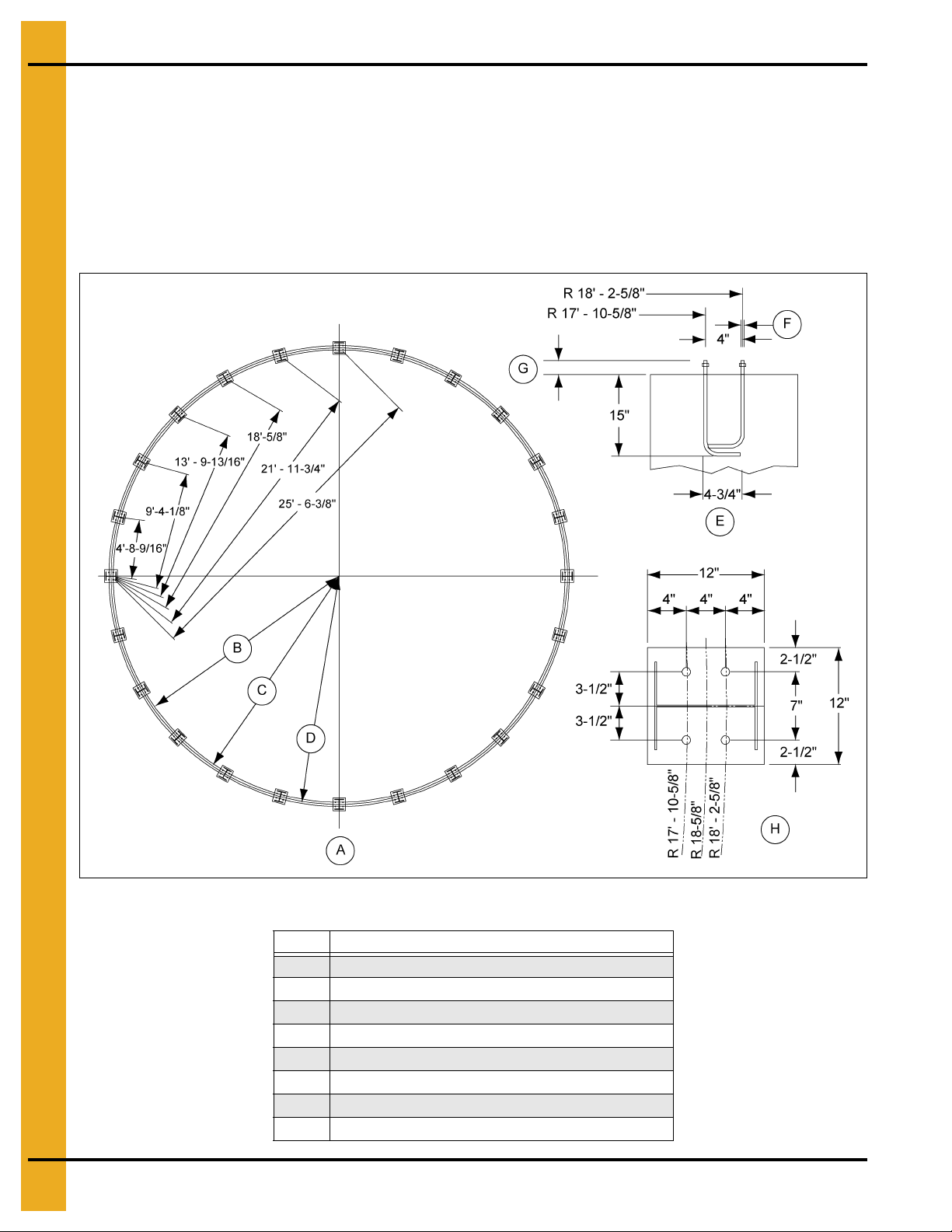
Chord dimensions shown from center of base plate to center of base plate.
Anchor bolts must be set with a template, not be hand.
All anchor bolts must be AISI1018 cold rolled steel. (Fy. = 60 KSI, Ft. = 70 KSI). Nuts and washers must
be a grade 5. Washers must be a minimum of 1" diameter 96 anchor bolts required. (See Figure 4B.)
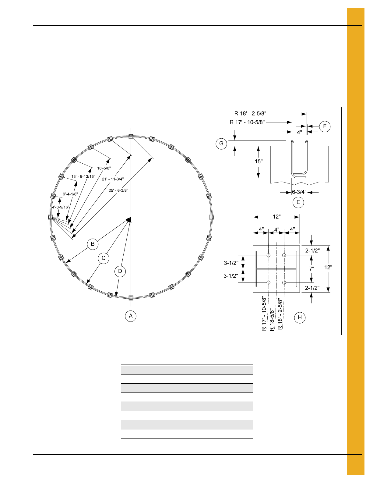
Figure 4B
Ref # Description
A Anchor Bolt Plan
B R 17' - 10-5/8" Inner Anchor Bolt
C R 18'-5/8" Base Pl ate Center
D R 18' - 2-5/8" Outer Anchor Bolt
E Section Detail
F 1" Diameter
G 3" Projection
H Plan Detail
18 PNEG-805 36' Diameter 40°/45° NCHT Commercial Hopper Tanks
Page 19
4. Foundations
36' Diameter Commercial Hopper Tank Foundation 19-22 Rings
Figure 4C
Ref # Description
A 18'-9" Radius
B 18'-2-5/8" Radius
C 17'-10-5/8" Radius
D 17'-5" Radius
E “C” Radius
F “D” Radius
G Footing Detail (NOTE: Not to scale.)
H 1/2" Expansion Joint
I 6 x 6 - 6/6 Wire Mesh
J 1 Extra #4 Hoop at 3" c/c Each Face at Top
K #4 Hoops Evenly Spaced Each Face
L “P” Bars Spacing at Center of Footing
M #4 Bars at 12" c/c Each Face with 12" Hook at Bottom
N 6" Maximum
O “N” #5 Hoops Evenly Spaced Top and Bottom
P #5 Bars at 18" c/c
PNEG-805 36' Diameter 40°/45° NCHT Commercial Hopper Tanks 19
Page 20

4. Foundations
36' Diameter Commercial Hopper Tank Foundation 19-22 Rings
(Continued)
# of Rings 20 22
A 2'-0" 2'-0"
B 10'-2" 11'-2"
C 11'-7" 11'-7"
D 22'-5" 22'-9"
N #5 at 12" c/c #5 at 12" c/c
P #5 at 6" c/c #6 at 5" c/c
#4 Rebar (Ft.) 2400 2400
#5 Rebar (Ft.) 3000 3300
#6 Rebar (Ft.) 2300 3000
6 x 6 - 6/6 Wire Mesh (Ft.2)
Concrete (Cu. Yds.) 122 128
960 960
NOTES:
1. The foundation design is based on a minimum allowable soil bearing capacity of 3000 PSF.
Bearing capacity of the soils should be determined by geotechnical investigation and be of
uniform bearing capacity.
2. The foundation site must be free of vegetation and debris and well drained.
3. The foundation must be founded below the frost line or placed on non-expansive frost free fill.
4. All material used for backfill inside the ring wall should be clean, well graded, crushed rock or a
sand-gravel mixture. Backfill should be placed in 6" lifts, 95% compaction.
5. All reinforcement must meet the requirements of ASTM A615 grade 60 deformed bars.
6. Lap all circumferential bars 35 bar diameters and stagger all laps in plans 3'-0". Estimates for material
do not include end laps.
7. Concrete must have a minimum compressive strength of 3000 PSI at 28 days, 6%-8% air
entrainment, 4" slump.
8. Codes: UBC 97, ACI 318-95.
9. Interior top slab may be crowned 2" to provide water drainage away from foundation. Crowning the
slab will reduce the clearance under the discharge.
20 PNEG-805 36' Diameter 40°/45° NCHT Commercial Hopper Tanks
Page 21
4. Foundations
36' Diameter Commercial Hopper Tank Foundation 19-22 Rings
(Continued)
Chord dimensions shown from center of base plate to center of base plate.
Anchor bolts must be set with a template, not be hand.
All anchor bolts must be AISI1018 cold rolled steel. (Fy. = 60 KSI, Ft. = 70 KSI). Nuts and washers must
be a grade 5. Washers must be a minimum of 1" diameter 96 anchor bolts required. (See Figure 4D.)
Figure 4D
Ref # Description
A Anchor Bolt Plan
B R 17' - 10-5/8" Inner Anchor Bolt
C R 18'-5/8" Base Plate Center
D R 18' - 2-5/8" Outer Anchor Bolt
E Section Detail
F 1" Diameter
G 3" Projection
H Plan Detail
PNEG-805 36' Diameter 40°/45° NCHT Commercial Hopper Tanks 21
Page 22
5. Column Heights
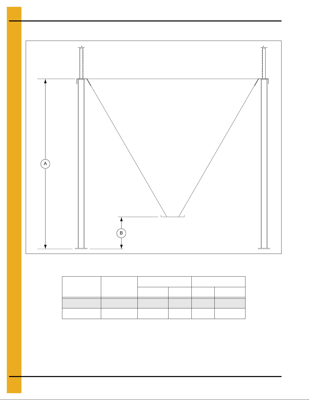
Standard Commercial Hopper Tank Column Heights
Figure 5A
“A” Dimension “B” Dimension
Tank Diameter Hopper Slope
Feet Meters Inches Millimeters
36' 40 15' - 11-1/2" 4.86 32 813
36' 45 20' - 1-1/2" 6.13 32 813
22 PNEG-805 36' Diameter 40°/45° NCHT Commercial Hopper Tanks
Page 23

6. Substructure Part List
Substructure Part List for 36' Commercial Hopper Tanks
Tank Size 36'-40° 36'-45°
Color Code White Light Blue
Column Weldment CHT-1580 (24) CHT-1566 (24)
Compression Angle Weldment CHT-1532 (24) CHT-1568 (24)
Compression Channel Weldment CHT-1535 (24) CHT-1535 (24)
Diagonal Column Brace CHT-1538 (96) CHT-1570 (144)
Horizontal Column Brace CHT-1539 (48) CHT-1539 (96)
Top Hopper Panel CHT-1540 (24) CHT-1571 (24)
Middle L.H. Hopper Panel CHT-1541 (24) CHT-1572 (24)
Middle R.H. Hopper Panel CHT-1542 (24) CHT-1573 (24)
Bottom Hopper Panel CHT-1543 (24) CHT-1574 (24)
Collar Weldment CHT-1445 (1) CHT-1577 (1)
Support Hardware CHT-1427 New (1) CHT-1578 (1)
PNEG-805 36' Diameter 40°/45° NCHT Commercial Hopper Tanks 23
Page 24

6. Substructure Part List
Typical NCHT36 Column
NOTE: In the field no material attaches to tabs on the inside of the column. Tabs used for manufacturing
purposes only. (See Figure 6A.)
Figure 6A
Ref # Description
A For Internal Use Only
24 PNEG-805 36' Diameter 40°/45° NCHT Commercial Hopper Tanks
Page 25

7. Hopper Section Assembly
Hopper Section Assembly 36' Diameter Hopper Tanks
Use a transit and surveyors rod to locate high and low areas in the concrete, before placing the support
columns on the anchor bolts. To assure level alignme nt, use the proper supplied shim (or) shims between
the concrete and base plate. After leveling, place the support column s over the anchor bolts, on the shims
and loosely fasten with nuts and washers (not supplied). (See Figure 7A.)
Figure 7A Column Shim Plate Detail (Use when necessary.)
Ref # Part # Description
A CHT-1425 Shim Plate
PNEG-805 36' Diameter 40°/45° NCHT Commercial Hopper Tanks 25
Page 26

7. Hopper Section Assembly
Bracing Assembly
Using 1/2"-13 x 1-1/2" hex head bolts for all brace connections with a washer on each side. Fasten the
diagonal and horizontal braces to the support columns as shown in Figure 7B. The horizontal brace
consists of two (2) formed channels placed back to back. Connect each set of diagonal braces at their
intersection. Do not tighten bolts until after hopper panels are installed to allow alignment.
Figure 7B Bracing Erection
Ref # Description
A Horizontal Braces (Two (2) per brace location.)
B Diagonal Braces (40° = Four (4) per Bay) (45° = Six (6) per Bay)
C Column Weldment
NOTE: Utilize SCHT-1963 spacer washer between the braces.
26 PNEG-805 36' Diameter 40°/45° NCHT Commercial Hopper Tanks
Page 27

7. Hopper Section Assembly
Install Compression Angle
Lift the compression angles on top of the columns so that the columns fit between th e inside and o utside
vertical plates of the compression angle. A 5/8"-11 x 2-3/4" bolt may be placed in the top hole of the
compression angle and the top plate of the column for alignment purposes. Using 5/8"-11 x 2" bolts,
connect the compression angles to the columns with a splice plate on each side as shown in Figure 7C.
Do not tighten bolts until after hopper panels are installed to allow alignment.
Figure 7C Compression Angle Erection
Ref # Description
A Compression Angle Segments
B Splice Plate
C Horizontal Compression Channel (See Figure 7D on Page 28.)
NOTE: Compression angle holes not shown for clarity. Structural bracing not shown for clarity.
36' Diameter hopper tanks have 24 columns.
PNEG-805 36' Diameter 40°/45° NCHT Commercial Hopper Tanks 27
Page 28

7. Hopper Section Assembly
Install Compression Channel
After the compression angle weldments have been aligned, place the compression channels under the
compression angle weldments and fasten with 5/8"-11 x 2" bolts to the column attachment plates. Fasten
the inside and outside vertical compression angle segments to the channel, see Figure 7D. Use the
supplied compression channel shim (CHT-1536) if necessary. Do not tighten bolts until hopper panels
are installed to allow alignment.
Figure 7D Compression Channel Erection
Ref # Part # Description
A CHT-1536 Channel Shim
B Fasten to column attachment plates
C Fasten to compression angle members
NOTE: Compression angle weldments not shown for clarity.
28 PNEG-805 36' Diameter 40°/45° NCHT Commercial Hopper Tanks
Page 29

7. Hopper Section Assembly
Hopper Panel Attachment Bolts
20 Ring and below 1/2" x 1-1/2" Bolts
21 Ring-22 Ring 5/8" x 2" Bolts
Install Hopper Panels
The 36' hopper bottom has three (3) sections. Apply caulk to all hopper section seams as shown
in Figure 7H on Page 30.
Step 1: Attach all the top panels to the compression angles using bolts. See chart below for bolt
specifications. Install the compression splice plates on the back side of the compression angle.
(See Figure 7E.) All top panel overlap seams use 1/2" x 1" bolts. Lap all panels as shown in Figure 7F.
Step 2: Assemble the left and right sides of the middle section to the top sections that were just installed.
Use 1/2" x 1" bolts for all middle section seams. Use 1/2" x 1-1/2" bolts at the corners of the panels where
three (3) or more panels overlap. Lap all panels as shown in Figure 7F.
Step 3: Once the middle panels are installed the bottom hopper panels and discharge collar may be
attached with 1/2" x 1" bolts at four (4) opposing points as shown in Figure 7I on Page 30. Complete this
assembly by laying the remaining panels - moving around in one direction and lapping all sheets the same
way. Do not tighten bolts until all hopper panels are attached to each other, the compression ring,
splice plates and discharge collar.
NOTE:
All bolts used in hopper assembly should be installed with the bolt heads to the inside of the hopper.
Figure 7F Lap Details Figure 7G
Ref # Description
A Middle Hopper Section Lap Detail
B Top/Bottom Hopper Section Lap Detail
Figure 7E Top Section and Splice Assembly
Ref # Description
A Top Panels
B Splice Plate using 1/2" x 1-1/2" Bolts
Ref # Description
A Inside
BOutside
PNEG-805 36' Diameter 40°/45° NCHT Commercial Hopper Tanks 29
Page 30

7. Hopper Section Assembly
Install Hopper Panels (Continued)
Figure 7H Caulking Detail
Ref # Description Ref # Description
A Top Hopper Panel C Caulking
B 1/2" Flange Head Bolts with Nut on Underneath Side D Middle Hopper Panels
Figure 7I Hopper Panel and Discharge Collar Assembly
Ref # Description
A Top Panel D Bottom Panel
B Left Middle Panel E Center Collar
C Right Middle Panel
30 PNEG-805 36' Diameter 40°/45° NCHT Commercial Hopper Tanks
Ref # Description
Page 31

7. Hopper Section Assembly
Tighten All Bolted Connections
Start at the bottom of the hopper and tighten all bolts, including anchor bolts, discharge collar, hopper
panels, splice plates and compression angle segments.
Install rack and pinion roller gate as shown in Figure 7J on Page 32, using 5/16" x 3/4" bolts.
When hopper structure has been completed, it should be level to within plus or minus 1/8" maximum
deviation, as compared to all other support columns as measured at the top to the compression angle ring.
The support columns must be plumb to within plus or minus 1/2" as measured from the top.
PNEG-805 36' Diameter 40°/45° NCHT Commercial Hopper Tanks 31
Page 32

7. Hopper Section Assembly
Install Rack and Pinion Roller Gate
If a rack and pinion gate is purchased, install as shown in Figure 7J, using 5/16" x 3/4" hardware.
NOTE: Top extension plate may have to be loosened prior to discharge collar connection.
Figure 7J Hopper Discharge Collar to Roller Gate
Ref # Description
A Hopper Panels
B Discharge Collar Weldment
C Roller Gate Assembly
D 5-1/2" Height
32 PNEG-805 36' Diameter 40°/45° NCHT Commercial Hopper Tanks
Page 33

8. Sidewall Assembly
Sidewall Erection Instructions
Before bolting the sidewall sheets together, check that you have the proper gauge steel for the first ring.
The higher gauge numbers denote the thinner materials. (For example, 22 gauge material is thinner than
14 gauge.) In erecting most grain bins the thinnest material usually goes on top, therefore the first sid ewall
ring you assemble will be the top ring of the bin. Check the various gauges of the bin with the color code
chart and begin building accordingly. REMEMBER assemble the top ring first.
Figure 8A
Ref # Description
A Left Panel
B Right Panel
C Concrete Foundation
D Sidewall Sheet
Once you have selected the proper gauge material, begin assembling all sidewall sheets in the following
manner: Standing on inside of the bin, place the left panel to the inside with the right panel to the
outside. (See Figure 8A.)
NOTE: The rope caulking is installed before each sheet is assembled. Wipe sheet clean where caulking
is to be applied. Refer to Page 34 for caulking placement.
Using correct size bin bolts throughout, begin assembling sidewall sheets end to end (overlapping the
same way throughout) until the ring is completed. All body sheet bolts are to be installed with the bolt head
and its neoprene washer to the outside and the nut on the inside. Do n ot tighten bolts u ntil all sh eets are
assembled and form a complete ring. Lifting of sidewall should be done with jacks and lifting brackets on
the stiffener bolt holes.
PNEG-805 36' Diameter 40°/45° NCHT Commercial Hopper Tanks 33
Page 34

8. Sidewall Assembly
Caulking Detail
Figure 8B Standard, Triple and Quad Punched Sidewall Sheets
as Viewed from Outside.
Apply one strip of caulking near the outside edge of the outer sheet and between the outer two (2) rows
of bolts, refer to Figure 8C. A strip of caulking 10" long, should be placed along the horizontal seams.
Before bolting the next ring in place, apply one strip of caulking 10" long on the front of the underlapped
sheet at each joint. Also, a 10" strip of caulking is to be placed along the lower horizo ntal edge of lapping
sheet at every vertical seam. This will fill the space that occurs between the holes caused by the
overlapped sheets. Additional 10" strips should be used to fill gaps that occur with heavier gauges.
Figure 8C As Viewed from Inside of Bin (Externally stiffened reverse rolled sheets shown.)
Ref # Description
A Quad Punch Caulking Detail
B Triple Punch Caulking Detail
C Double Punch Caulking De tail
D Laminated Sheet Detail (Caulking not shown.)
34 PNEG-805 36' Diameter 40°/45° NCHT Commercial Hopper Tanks
Page 35

8. Sidewall Assembly
Decal Sheet Placement
NOTE: The decal sheets are located in the second ring from the top, evenly spaced around the diameter
of the bin.
Figure 8D 2 Post (T wo (2) rows of stiffeners used on each sidewall sheet.)
NOTE: Dashed lines represent stiffener locations.
PNEG-805 36' Diameter 40°/45° NCHT Commercial Hopper Tanks 35
Page 36

9. Lifting Jack
Lifting Jack Usage
Give some thought before starting the bin on location of door and other accessories. Proper placement of
lifting jacks in relationship to anchor bolts could make a difference on odd or even ring bins. Attachment
of lifting brackets should be made on the stiffener row of bolts. The sidewall sheets are also staggered
1/2" from end to end.
Figure 9A Anchor Jacks Securely
Anchor all jacks securely with metal stakes and cable. Now raise the bin just high enough to assemble
the next ring. When lifting the bin, crank all jacks at an equal rate. This will prevent bowing previously
assembled rings and make for easier hole alignment. To the inside of the first ring, bolt the next ring.
Be sure to stagger the sheets and select the proper gauge material. To avoid excessive pulling of the holes
in the sidewall, some stiffener lap and splice connections may go together easier if the sidewall is not
tightened until the stiffeners have been put in place. Lower the bin on the foundation after assembling and
tightening bolts on the new ring or rings. Now, re-bolt the lifting straps to the lowest ring in place thus far.
NOTES: Add inside and outside ladders to bin walls as you continue to raise the bin.
The number of lifting jacks required is best determined by personal experience. Factors such as
bin size, soil compaction, wind velocity, jack design, etc., are all to be considered when deciding
how many to use. If in doubt, use one jack on every other stiffener (one per sheet). Be sure to
use heavy duty jacks for commercial installations.
36 PNEG-805 36' Diameter 40°/45° NCHT Commercial Hopper Tanks
Page 37

Color Code Chart 2.66" Commercial Stiffeners
NOTE: Some colors are different than those used for sidewall sheets.
* NOTE: Only Orange on 1 ring stiffener.
Stiffener Gauge Color Code
15 Red/Orange*
14 Green/Orange*
13 Dark Blue
12 Black
11 Pink
10 Light Blue
9 Purple
8 Yellow
6 White
5 Fluorescent Green
10. Color Code Charts
5+12 Gold/Black
5+10 Gold/Light Blue
5+8 Gold/Yellow
Color Code Chart 2.66" Sidewall Gauges
NOTE: Some colors are different than those used for stiffener sheets.
Sidewall Gauge Color Code
22 White
20 Red
19 Black/Y e llow
18 Orange
17 Pink/Light Blue
16 Blue
15 Brown/Red
14 Green
13 Yellow/Blue
12 Black
11 Pink
10 Light Blue
9 Blue/Orange
8 Yellow
PNEG-805 36' Diameter 40°/45° NCHT Commercial Hopper Tanks 37
Page 38

11. Hardware
CAUTION
Under no condition shall any other bolts be substituted for those supplied by
the manufacturer.
Grade 2 Bolts
1. Grade 2 bolts are designated with a plain head and are not
used in GSI grain bins/silos.
Grade 5 Bolts
2. Grade 5 bolts are designated by three (3) slash marks on the head. All 5/16" diameter
bolts are to be grade 5 or higher.
Grade 8 Bolts
3. Grade 8 bolts are designated by six (6) slash marks evenly spaced out around the
head of the bolt.
Grade 8.2 Bolts
4. Grade 8.2 bolts are designated by six (6) slash marks on the head in a sunrise pattern.
All 3/8" diameter bolts are to be grade 8 or grade 8.2.
Identifying Bolt Grades
NOTE: Bolts should not be tightened in excess of the torque specifications.
Torque (ft. lbs.)
Bolt Size Minimum Maximum
5/16"-18 15 20
3/8"-16 35 42
7/16"-14 65 72
1/2"-13 95 105
38 PNEG-805 36' Diameter 40°/45° NCHT Commercial Hopper Tanks
Page 39

11. Hardware
0.3125" x 0.750" Pre-assembled with a steel backed
neoprene washer.
This bolt is used to connect horizontal and vertical seams for
14 gauge and thinner sidewall sheets to each other. It is also
used in attaching roof panels to the top sidewall sheet and
attaching roof panels and flashing to the center collar.
A Side View
B 0.950" (2.41 cm)
C 0.750" (1.90 cm)
DTop View
E Grade 5
0.3125" x 1.250" Pre-assembled with a steel backed
neoprene washer.
This bolt is primarily used to connect roof panels together
where they overlap. It is also used at the bottom of the
flat bottomed bins to attach the base angle to the sidewall
sheet and to attach the sealing strip to the bottom edge of a
sidewall sheet.
A Side View
B 1.437" (3.65 cm)
C 1.250" (3.17 cm)
D Top View
E Grade 5
Hardware Identification Notes
Refer to 2.66" Commercial Tank Bolting Requirements for Complete
Bolt Usage
S-275
S-277
PNEG-805 36' Diameter 40°/45° NCHT Commercial Hopper Tanks 39
Page 40

11. Hardware
0.375" x 1.000" Pre-assembled with a steel backed
neoprene washer.
This bolt is used in horizontal and vertical seams for
13 gauge through 12 gauge laminate sidewall to attach the
sheets to each other. It is also used to attach the stiffener to
the sidewall sheet for up to 10 gauge sidewall. It is not used
to splice the stiffeners together on the flanges where they
connect to each other or the splice plates. These are also
used to attach the hopper panels to the hopper support
beam for the NCHT’s with diameters of 30' and less.
NOTE: 3/8" x 1-1/2" (S-5060) A bolts are provided for
laminated stiffeners and splices.
A Side View D Top View
B 1.223" (3.11 cm)
EGrade 8
C 1.000" (2.54 cm) F Grade 8.2
0.375" x 1.500" Pre-assembled with a steel backed
neoprene washer.
It is used to connect the stiffener to the sidewall at
locations where a splice plate is used to connect the
stiffener and to connect laminated stiffeners to the
sidewall sheets. It is also used to bolt stiffeners to
9 gauge and thicker sidewall. This bolt is also used
to bolt horizontal and vertical seams together on
11 gauge laminated and thicker and some overlap
seams. It is only used to attach the stiffener and the
splice plate to the sidewall. The flanges where the
stiffeners bolts to the splices plates use a
different bolt (one without a rubber washer).
A Side View D Top View
B 1.725" (4.38 cm)
EGrade 8
C 1.500" (3.81 cm) F Grade 8.2
Refer to 2.66" Commercial Tank Bolting Requirements for Complete Bolt
Usage (Continued)
S-455
S-5060
40 PNEG-805 36' Diameter 40°/45° NCHT Commercial Hopper Tanks
Page 41

11. Hardware
0.375" x 1.000" Hex flanged head without a plastic
sealing washer.
This bolt is used to splice the stiffeners together on the
flanges. A steel flat washer is used on the nut side of the
connection. They are also used on the roof rafter splices
for commercial roof systems.
A Side View
B 1.377" (3.50 cm)
C Top View
D Grade 8
E Grade 8.2
0.375" x 1.500" Hex flanged head without a plastic
sealing washer.
This bolt is used to attach the flanges of the 5 gauge
base stiffener to the splice plates and splice laminated
stiffeners together. A steel flat washer is used on the
nut side of the connection.
A Side View
B 1.873" (4.76 cm)
C Top View
D Grade 8
E Grade 8.2
Refer to 2.66" Commercial Tank Bolting Requirements for Complete Bolt
Usage (Continued)
S-7927
S-7928
NOTE: The only washers shipped loose with the bins are the steel flat washers. The 5/16" steel flat washer
PNEG-805 36' Diameter 40°/45° NCHT Commercial Hopper Tanks 41
(S-845) is used where the base angle attaches to the sheet and some are used at the main e ave
clips. The 3/8" steel flat washers (S-248) are used at the stiffener splices and some are used in
the roof rafter splices.
Page 42

11. Hardware
Color Chart for Bin Hardware Bucket Lids
Part # Color Description
S-275 5/16" x 3/4" Bolt pre-assembled with a steel backed sealing washer
S-277 5/16" x 1-1/4" Bolt pre-assembled with a steel backed sealing washer
S-396 5/16" Hex nut
S-455 3/8" x 1" Bolt pre-assembled with a steel backed sealing washer
S-456 3/8" Hex nut
S-5060 3/8" x 1-1/2" Bolt pre-assembled with a steel backed sealing washer
S-7927 3/8" x 1" Hex flanged head bolt without
S-7928 3/8" x 1-1/2" Hex flanged head bolt without sealing washer
S-8479 7/16" Special recessed nuts
Dark Blue
Black
Red
Grey
Yellow
Orange
Light Green
Dark Brown
Light Brown
sealing washer
S-9373 3/8" Hex flanged nuts
S-9444 7/16" x 2-1/2" Bolt pre-assembled with a steel backed sealing washer
S-9445 3/8" x 2" Bolt pre-assembled with a steel backed sealing washer
S-9470 7/16" x 2" Bolt pre-assembled with a steel backed sealing washer
Dark Purple
Dark Green
Light Blue
Light Purple
42 PNEG-805 36' Diameter 40°/45° NCHT Commercial Hopper Tanks
Page 43

11. Hardware
2.66" Commercial Tank Bolting Requirements - 2 Stiffeners per
Sidewall Sheet
Sidewall Seams and Stiffener to Sidewall Bolt Usage
Sidewall Gauge Horizontal Seam Vertical Seam Stiffener to Sidewall Overlap Seam
20-19
18T
17T-16T
15Q-14Q
13Q-10Q
5/16'' x 3/4''
[10]
5/16'' x 3/4''
[22]
5/16'' x 3/4''
[22]
5/16'' x 3/4''
[22]
3/8'' x 1''
[22]
1. T - Triple punched sheets (36 Holes in vertical seams.)
Q - Quad punched sheets (48 Holes in vertical seams.)
All bolts are standard bin bolts with neoprene washers. For horizontal and vertical seam bolts, the bolt
head and neoprene washers are on the outside of the bin. Refer to stiffener instructions on stif fener
to sidewall bolt usage on Page 44.
5/16'' x 3/4''
[24]
5/16'' x 3/4''
[36]
5/16'' x 3/4''
[36]
5/16'' x 3/4''
[48]
3/8'' x 1''
[48]
3/8'' x 1''
[8]
3/8'' x 1''
[16]
3/8'' x 1''
[24]
3/8'' x 1''
[24]
3/8'' x 1''
[24]
5/16'' x 3/4''
[2]
5/16'' x 3/4''
[2]
5/16'' x 3/4''
[2]
5/16'' x 3/4''
[2]
3/8'' x 1''
[2]
2. Hardware part numbers
5/16'' x 3/4'' (S-275)
3/8'' x 1'' (S-455)
3. See Pages 44-46 for special instructions on stiffener to sidewall bolt usage for stiffener splices and
laminated stiffeners.
4. Use 5/16'' bolts and nuts when joining 14 gauge to 13 gauge on horizontal seams.
Figure 11A 18 Gauge Sidewall Sheet
Ref # Descrip t ion
A Overlap Seam
B Vertical Seam
C Horizontal Seam
D Stiffener to Sidewall Standard Stiffened Punched
PNEG-805 36' Diameter 40°/45° NCHT Commercial Hopper Tanks 43
Page 44

12. Stiffeners
Universal Stiffener and Splice Hardware
Stiffeners Splicing Systems
12 Gauge to 12 Gauge
and Thinner
12 Gauge to 11 Gauge
through
8 Gauge to 5 Gauge, 6 Gauge
5 Gauge, 6 Gauge to 5 Gauge,
6 Gauge
5 Gauge to Laminated
Laminated to Laminated
Offset/Lapped Stiffener
No Separate Splices Plate
Use SS-7053 Splice
Color Code: Yellow
Use SS-7053 Splice
Color Code: Yellow
Use SS-6966 or SS-7427
Splice 2 per Joint
Splice Hardware Usage
(Not Including Sidewall to Splice Bolts)
Stiffeners Splicing Systems Hardware Part # Description Qty
14 Gauge and 15 Gauge Offset Stif fener Joint
12 Gauge and 13 Gauge Offset Stiffener Joint
10 Gauge and 11 Gauge
SS-7053
8 Gauge Splice Plate
S-7927 3/8'' x 1'' 8
S-9373 3/8" Flange Nuts 8
S-7927 3/8'' x 1'' 10
S-9373 3/8" Flange Nuts 10
S-7927 3/8'' x 1'' 16
S-9373 3/8" Flange Nuts 16
8 Gauge and 9 Gauge
5 Gauge and 6 Gauge
Laminated SS-6966 or SS-7427
SS-7053
8 Gauge Splice Plate
SS-7053
8 Gauge Splice Plate
Stiffener to Sidewall Hardware Usage
Stiffeners Hardware Part # Description
Stiffener to Sidewall
SS-7053
Splice to Sidewall
Laminated Stiffener
to Sidewall
S-7927 3/8'' x 1'' 20
S-9373 3/8" Flange Nuts 20
S-7928 3/8'' x 1-1/2'' 20
S-9373 3/8" Flange Nuts 20
S-7928 3/8'' x 1-1/2'' 30
S-9373 3/8" Flange Nuts 30
S-455 3/8" x 1"
S-456 3/8" Nuts
S-5060 3/8" x 1-1/2"
S-456 3/8" Nuts
S-5060 3/8" x 1-1/2"
S-9373 3/8" Flange Nuts
44 PNEG-805 36' Diameter 40°/45° NCHT Commercial Hopper Tanks
Page 45

Commercial Stiffeners for 2.66" Corrugation
12. Stiffeners
Figure 12A
Ref # Part # Description Length
A SS-6929 2 Ring Laminated Stiffener 71.906" (182.642 cm)
B SS-6989 Offset Base Stiffener 87-1/8" (180.260 cm)
C SS-7311 Base Stiffener 80.094" (203.438 cm)
D SS-7312 Universal Stiffener Laminated Base Weldment 88.094" (223.758 cm)
E SS-7065 14 Gauge and 15 Gauge 2 Ring Stiffener 70.969" (180.260 cm)
F SS-6982 12 Gauge and 13 Gauge 2 Ring Stiffener 70.969" (180.260 cm)
G SS-7083 10 Gauge and 11 Gauge 2 Ring Stiffener 63.938" (162.401 cm)
H SS-6923 5 Gauge, 6 Gauge, 8 Gauge and 9 Gauge 2 Ring Stiffener 63.938" (162.401 cm)
I SS-6966 or Laminated Back Plate Splice 22" (55.88 cm)
I SS-7427 Laminated Back Plate Splice 11-3/4" (29.85 cm)
J SS-7064 Offset 1 Ring Stiffener 38.969" (98.981 cm)
K SS-7053 8 Gauge Splice 14" (35.56 cm)
L SS-7066 1 Ring Top 12.469" (31.671 cm)
PNEG-805 36' Diameter 40°/45° NCHT Commercial Hopper Tanks 45
Page 46

12. Stiffeners
2.66" Corrugation Commercial Stiffener Splice Details
When installing bottom stiffeners, you may find that in some cases the stiffener with base plate attached
will not rest on support structure. Shim plates have been furnished and should be used to fill opening
between base plate and compression element. See Page 58 for detail.
IMPORTANT: If shim plates are not used where required, the downward pressure of the stiffeners will not
be transferred directly to the foundation and bin failure could result.
Figure 12B
Ref # Description
A Splice Plate Joint Detail (Non-Offset Joint)
B Splice Plate 8 Gauge (Fluorescent Green) (SS-7053)
C Base Stiffener (SS-6976)
D 2 Ring Standard Stiffener
E 3/8" Diameter Hex Flanged Head Bolt (No Sealing Washer)
F Offset Joint Connection Detail
G Standard Offset Stiffener
H 3/8" Flange Nut
I Splice Plate Joint (Top View)
See Page 34 and Pages 44-46 for further details.
46 PNEG-805 36' Diameter 40°/45° NCHT Commercial Hopper Tanks
Page 47

12. Stiffeners
2.66" Corrugation Commercial Stiffener Splice Details (Continued)
Figure 12C Figure 12D 10 Gauge and 11 Gauge Stiffener
Ref # Description
A 14 Gauge and 15 Gauge to 14 Gauge and
15 Gauge Offset Connection Detail
B 14 Gauge and 15 Gauge to 13 Gauge and
12 Gauge Offset Connection Detail
C Bolt hole not used in 14 gauge and 15 gauge.
Do not drill.
Bearing Splice
Ref # Description
A Splice Plate 8 Gauge (SS-7053)
B 10 Gauge or 11 Gauge Standard Stiffener
C 3/8" Diameter Hex Flanged Head Bolt
(No Sealing Washer)
D Bolt holes in splice plate not used. Do not drill.
PNEG-805 36' Diameter 40°/45° NCHT Commercial Hopper Tanks 47
Page 48

12. Stiffeners
2.66" Corrugation Commercial Stiffener Splice Details (Continued)
Figure 12E 5 Gauge, 6 Gauge, 8 Gauge and 9 Gauge Stiffener Bearing Splice
Ref # Description
A Splice Plate 8 Gauge (SS-7053)
B 3/8" Diameter Hex Flanged Head Bolt (No Sealing Washer)
C 5 Gauge, 6 Gauge, 8 Gauge and 9 Gauge Standard Stiffener
NOTE: Install bolts in all bolt hole locations on stiffener splices.
48 PNEG-805 36' Diameter 40°/45° NCHT Commercial Hopper Tanks
Page 49

12. Stiffeners
2.66" Corrugation Commercial Stiffener Splice Details (Continued)
Figure 12F Laminated Stiffener Splice 2.66" Corrugation
Ref # Description
A Stiffener Detail for SS-6929
B Laminated Stiffener Assembly (SS-6929)
C Back Plate Splice (Two (2) per Connection) (SS-6966)
D Use 3/8" x 1-1/2" Bin Bolt
E Bolting Detail for Laminated to Laminated Stiffener Connection
F 3/8" x 1-1/2" Flange Bolts and 3/8" Flange Nuts (30)
NOTE: Install bolts in all bolt hole locations on stiffener splices.
PNEG-805 36' Diameter 40°/45° NCHT Commercial Hopper Tanks 49
Page 50

12. Stiffeners
2.66" Corrugation Commercial Stiffener Splice Details (Continued)
Figure 12G
Ref # Description
A Special Laminated Stiffener Splice Detail (SS-7427 Substituted for SS-6966)
B Laminated Stiffener Assembly (SS-6929)
C Laminated Stiffener Splice (SS-7427)
D Use 3/8" x 1-1/2" Bin Bolt and 3/8" Hex Nut
E Use 3/8" x 1-1/2" Flange Bolt and 3/8" Flange Nut
F Bolting Detail for Laminated to Laminated Stiffener Connection
G 3/8" x 1-1/2" Flange Bolts and 3/8" Flange Nuts (30)
NOTE: Install bolts in all bolt hole locations on stiffener splices.
50 PNEG-805 36' Diameter 40°/45° NCHT Commercial Hopper Tanks
Page 51

12. Stiffeners
2.66" Corrugation Commercial Stiffener Splice Details (Continued)
Figure 12H Laminated to Universal Stiffener Splice 2.66" Corrugation
Ref # Description
A Bolting Detail for Laminated to Universal Stiffener Connection
B 3/8" x 1-1/2" Flange Bolts and 3/8" Flange Nuts (20)
NOTE: Install bolts in all bolt hole locations on stiffener splices.
PNEG-805 36' Diameter 40°/45° NCHT Commercial Hopper Tanks 51
Page 52

12. Stiffeners
Non-Laminated Stiffener to Sidewall Detail
Figure 12I Non-Laminated Stiffener to Sidewall Detail
Ref # Description
A 3/8" Bin Bolt with a Steel Backed Neoprene Washer
B 3/8" Flange Nut (S-456)
C Non-Laminated Stiffener
D Outside of Bin
52 PNEG-805 36' Diameter 40°/45° NCHT Commercial Hopper Tanks
Page 53

Laminated Stiffener to Sidewall Detail
12. Stiffeners
Figure 12J Laminated Stiffener to Sidewall Detail
Ref # Description
A 3/8" Bin Bolt with a Steel Backed Neoprene Washer
B 3/8" Flange Nut
C Laminated Stiffener
PNEG-805 36' Diameter 40°/45° NCHT Commercial Hopper Tanks 53
Page 54

12. Stiffeners
Universal Stiffener Starting Location - 2.66" Reverse Corrugation
Outside Stiffener Only
For sidewall to stiffener connections, use 3/8" x 1" bin bolt except horizontal seam. 19 Gauge and
20 gauge sidewall sheet will bolt four (4) locations per sheet. 18 Gauge and thicker sidewalls will bolt
every 2.66".
NOTE: Splice plate and laminated stiffener to sidewall connection, use 3/8" x 1-1/2" bin bolts.
Offset joints and 8 gauge splice plated joints, use 3/8" x 1" hex flanged head bolts. All other stiffener joints,
use 3/8" x 1-1/2" hex flanged head bolts. Washers used on the nut side of all stiffener joint connections.
(See Figure 12K.)
Figure 12K
Ref # Description
A Odd Ring Bins
B 2 Ring Offset Stiffener (SS-7065 or SS-6982)
C 1 Ring Offset Stiffener (SS-7064)
D Even Ring Bins
E Horizontal Seam
54 PNEG-805 36' Diameter 40°/45° NCHT Commercial Hopper Tanks
Page 55

13. Roof Rafter Installation
Standard Roof Stiffener Detail - 2.66" Corrugation Outside
Stiffener Only
NOTE: Insert corrugation spacer (S-7041) into corrugation.
Figure 13A
Ref # Part # Description
A SS-7066 Top Stiffener
B CRP-5333 Roof Beam Stiffener (One per Sidewall Sheet)
C S-5060 3/8" x 1-1/2" Bolt
D S-7041 Corrugation Spacer
E S-455 3/8" x 1" Bolt
F Place neoprene washer between spacer washer and sidewall.
PNEG-805 36' Diameter 40°/45° NCHT Commercial Hopper Tanks 55
Page 56

13. Roof Rafter Installation
Special Roof Instructions for 36' Diameter Commercial
Hopper Tank
The 36' diameter commercial hopper tank comes standard with 12 roof rafter assemblies that are not
included in the 30° roof manual (PNEG-1092). Install one roof rafter per sidewall sheet. Please refer to the
roof manual for the complete roof assembly details.
NOTE: Each rafter has two (2) sections.
Figure 13B
Ref # Part # Description Ref # Description
A CRP-5274 Top Rafter Section E Sidewall
B CRP-4759 Bottom Rafter Section
C Z-Collar G See Detail 2 on Page 58
D Roof Panel
56 PNEG-805 36' Diameter 40°/45° NCHT Commercial Hopper Tanks
F See Detail 1 on Page 57
H See Detail 3 on Page 58
Page 57

13. Roof Rafter Installation
Special Roof Instructions for 36' Diameter Commercial Hopper
Tank (Continued)
Figure 13C Detail 1 - Rafter to “Z” Collar Connection
Ref # Description
A Roof Flashing Bolts Here
B Bolts in these Holes are to Hold Roof Sheet and Roof Truss
C Isometric View of Rafter and Clip Assembly
D “Z” Collar (CRP-4687)
E Rafter Support Clip (CRP-5307)
F Top Roof Truss (CRP-5274)
G Side Profile
PNEG-805 36' Diameter 40°/45° NCHT Commercial Hopper Tanks 57
Page 58

13. Roof Rafter Installation
Special Roof Instructions for 36' Diameter Commercial Hopper
Tank (Continued)
Figure 13D Detail 2 - Rafter to Stiffener Connection
Ref # Part # Description
A CRP-4759 Bottom Roof Rafter
B CRP-5333 Top Roof Stiffener Bracket
C R-007 Roof Eave Clip
D 3/8" x 1" Hex Flanged Head Bolt
E 3/8" Flat Washer
F
Use stiffener holes for placement.
See standard roof stiffener detail. (See Page 55.)
Figure 13E Detail 3 - Rafter Splice Connection
Ref # Part # Description
A PR-1874 Rafter Splice
B
58 PNEG-805 36' Diameter 40°/45° NCHT Commercial Hopper Tanks
Use 3/8" x 1" hex flanged head bolts for rafter splice.
Use two (2) flat washers for all connections.
Page 59

Wind Ring Assembly
14. Wind Ring
Ref # Description
A 3/8" x 1" Flanged Head Bolts
B 3/8" Flange Nuts
C Wind Ring Coupler
D C-Clamp (SS-7248)
Figure 14A
1. To connect wind ring pipe to the stiffeners, attach with 3/8" x 1" bolts through the flange of the
stiffener. In some cases field drilling of wind ring locations may be required. (See Figure 14A.)
2. Attach wind ring pipe section to stiffener using two (2) 3/8" x 6" (SS-7248) wind ring clamps.
3. Place pipes end to end without overlapping. Fasten together using two (2) wind ring couplers and
six (6) 3/8" x 1" flanged head bolts with flanged nuts. Couplers should be centered on the seam
of pipes.
Wind rings must be installed in relation to the ladder rungs as shown here, to ensure
compliance with O.S.H.A. regulations. (See Figure 14B.)
Ref # Description
A 1-1/2" Minimum
B 4-1/2" Minimum
Figure 14B
PNEG-805 36' Diameter 40°/45° NCHT Commercial Hopper Tanks 59
Page 60

15. Base Stiffener
Stiffener Shim Plate Detail (Use when Necessary)
The shim plates should be used where necessary to ensure the base plates are firmly supported by the
columns. Use the shim plates to fill any gaps between the base plate and the compression weldment.
(See Figure 15A.) Attach the base stiffener to the stiffener column and compression weldment with
5/8" x 2-3/4" bolts (two (2) per stiffener). Place a washer on the top side of the stiffener base plate.
Figure 15A
Ref # Part # Description
A CHT-1160 Shim Plate
60 PNEG-805 36' Diameter 40°/45° NCHT Commercial Hopper Tanks
Page 61

16. Doors
Access Door Weldment Assembly Hardware Package (PLS-41985)
Figure 16A
Ref # Part # Description
A ACD-4513 Access Door Handle
B ACD-4 531 Door Cover
C ACD-4514 Latch Bar
D ACD-4515 Access Inner Door Handle (2)
E ACD-4549 Bottom Ring Inner Door Hinge (2)
F ACD-4548 Inner Door
G S-3867 Sleeve, Plastic RD Door Handle (2)
SS-7211 and
H
SS-7214
I ACD-4505 Access Door Hinge
J 5/16" x 3/4" Bolt
K #10 Screw
L 5/16" x 3/4" Bolt and Nut
M 3/8" x 1-1/2" Full Threads
N ** 3/8" Washers (Use as Needed)
O 3/8" x 1" Bolt
P Assembled Side Detail
Q ACD-4509 Access Inner Door Hi nge Bracket
Access Door Weldment
** The quantity of 3/8" washers needed may vary depending on the sidewall gauges.
PNEG-805 36’ Diameter 40°/45° NCHT Commercial Hopper Tanks 61
Page 62

17. Aeration
Aeration Package (Optional)
The 36' aeration package is installed through the sidewall of the bottom ring of the ho pper tank. An extra
sheet of sidewall is provided to reinforce the aeration opening. A platform for supporting the fan units on
the side of the tank is not provided.
Step 1: Install the two (2) extra sidewall sheets 180° opposite of each other in the location where the
aeration tubes are to be located.
Step 2: Using 18" reinforcement sleeve (SCHT-2458) as a template, mark hole in sidewall for cutting.
Locate hole 2" above compression angle. Do not locate hole on vertical sidewall seam.
Step 3: Using a torch or saw, cut the hole in sidewall sheets for tube.
Step 4: Install reinforcement sleeve in sidewall hole and weld in place.
Step 5: Insert elbow joint through sleeve and weld or screw in place as shown.
Step 6: Connect tube coupler to the tube with the clamp provided.
Step 7: Place tube with tube coupler in elbow and install angle hold-downs. Six (6) angles with
corrugated pieces welded on them are supplied for each tube (three (3) per side). Bolt
or weld each angle to the hopper sheet and screw or weld the corrugated material to the
perforated tube (#14 x 1" self-drilling). Weld or screw elbow joint to tube.
Step 8: Bolt or weld on angle ring for attachment of fan.
Step 9: Touch up any welded areas with a rust inhibitive type paint.
62 PNEG-805 36' Diameter 40°/45° NCHT Commercial Hopper Tanks
Page 63

Aeration Package (Optional) (Continued)
17. Aeration
Figure 17A Typical Installation
Ref # Description
A Reinforcement ring weld to sidewall inside and outside (SCHT-2458)
B 18" Angle Ring (Bolt or weld to elbow tube after installation.) (F-895)
C Elbow Tube
D Two (2) Layers of Sidewall
E Bin Hopper
F Corrugated perforated tube (18" diamet er standard) with corruga ted coupler.
G Hold-Down (Typical)
Mark location (see side profile on Page 64) and field cut a 18-1/8". Diameter hole between
H
stiffeners to allow installation of the elbow. Do not locate hole on vertical sidewall seam.
PNEG-805 36' Diameter 40°/45° NCHT Commercial Hopper Tanks 63
Page 64

17. Aeration
System Airflow Rating (CFM)
A-CHT3640-14 5644
A-CHT3645-14 5644
Aeration Package (Optional) (Continued)
Figure 17B Side Profile
Ref # Description
A 18" Angle Ring (Bolt or weld to elbow tube.) (F-895)
BElbow Tube
C Corrugated Coupler
D Hold-Down
E Perforated End Cap/Heavy Duty X-Brace
64 PNEG-805 36' Diameter 40°/45° NCHT Commercial Hopper Tanks
Page 65

Aeration Package (Optional) (Continued)
17. Aeration
Figure 17C
Ref # Description
A Weld Detail
B 18" Angle Ring (F-895) (Bolt or weld to elbow tube after tube installation.)
C Weld Reinforcement Sleeve to Sidewall
D Two (2) Layers of Sidewall
E Weld Reinforcement Sleeve to Sidewall, Weld or Screw Elbow to Sleeve
F Screw or Weld Elbow to Aeration Tube Coupler
G Screw or Weld to Aeration Tube
H Bolt or Weld to Hopper Sheet
I Corrugated Angle Hold-Down Attachment Detail
J Weld to Hopper or Bolt with 1/2" Bolts (Field drill and replace all seam bolts.)
K Screw or Weld to Tube
PNEG-805 36' Diameter 40°/45° NCHT Commercial Hopper Tanks 65
Page 66

18. Ladders
Bin Diameter
Hopper
Slope
# of Support
Channel
Hopper Ladder
Brackets
36' 40 5 10
36' 45 6 12
Hopper Ladder Supports
Figure 18A
Ref # Description Ref # Description
A Ladder F Ladder Standoff
B 44" Typical
C Support Column H Field Drill Hole 5/16" x 1-1/4" Hardware
D Ladder Bracket
E Support Channel
66 PNEG-805 36' Diameter 40°/45° NCHT Commercial Hopper Tanks
G Ladder Support Detail
I 5/16" x 3/4" Hardware
Page 67

Hoist Instructions
Recommendations for hoisting completed tank onto hopper bottom structure.
19. Hoisting
(All parts mentioned in this section are not
furnished.) A crane is normally used to lift the tank and place
it on top of the substructure. Technique of hoisting of the comple te tank on the hopper structure is in large
part based on personal experience, equipment and manpower. The following recommendations are
intended as a guideline only.
1. Before lifting the tank the following should be checked:
a. The columns and substructure should be checked for levelness and verified plumb and leveled
if necessary.
b. Final ladder and safety cage and door locations should be determined and clearance at these
locations verified.
c. Proper provisions should be made for safe working platforms around the top of the substructure.
2. Lifting technique are largely influenced by personal experience and equipment capacity however
general recommendations as follows:
a. Twelve (12) lifting brackets should be attached at the stiffeners. At least one bracket on every
other stiffener should be used. These would typically be attached in the third ring from the bott om
of the tank. Brackets should attach to a minimum of four (4) bolts through the stiffener. Attach
cables to the lift brackets and to the crane hook, which has been lowered throug h the center ring
opening. Cables should be sized to handle the entire weight of the bin. Make all lift cables of equal
length before the bin is lifted. (See Figure 19A and Figure 19B.)
b. To prevent distortion of the assembled tank a “spider” or horizontal bracing is recommended.
A suggested method of this is illustrated in the following details. This may be done by using
a center “hub” and pipe. The center hub would typically be made of 6" schedule 40 pipe with
four (4) 3" x 3" x 3/8" angles welded to it and the pipe bolting to the hub. The second smaller
pipe would bolt to the lifting brackets attached to the stiffeners. (See Figure 19C on Page 68.)
Four (4) horizontal braces are recommended.
c. Use of temporary bracing across the peak collar may be needed to guide the cable. This should
be made easily removable.
Figure 19A
Ref # Description
A Stiffener
B Lift Bracket Every Other Stiffener
Figure 19B
PNEG-805 36' Diameter 40°/45° NCHT Commercial Hopper Tanks 67
Page 68

19. Hoisting
Hoist Instructions (Continued)
Figure 19C
Ref # Description Ref # Description
A 2-1/2" Pipe H Sidewall Support Angle
B Bolt Hole
C 2" Pipe J Sidewall Stiffener
D 3-1/2" x 1-1/2" Slots (2)
E Hub Assembly L Extra Nut or Sidewall Spacer
F 6" Schedule 40 Pipe
G 3" x 3" x 3/8" Angle Iron Welded to Hub (Four (4) Places)
I Sidewall Sheet
K Lifting Bracket 3" x 3" x 3/8" Angle
M 3/8" Grade 8 Bolts (4)
3. It will generally simplify the setting process to bend the sealing lip inward slightly to allow sidewall
sheet clearance. Once tank is in place, bolt the sealing strip to the bottom of the sheet. Shim between
the bottom of the stiffener and the compression angle ring for level alignment if necessary.
4. After tank is secured remove the spider or horizontal bracing and all hoisting attachments
and cables.
68 PNEG-805 36' Diameter 40°/45° NCHT Commercial Hopper Tanks
Page 69

Hoist Instructions (Continued)
19. Hoisting
Figure 19D Tank on Support Columns
Ref # Description
A Sidewall Base Stiffener
B Sidewall
C Compression Angle Ring
D Support Column Weldment
After lifting the tank clean all dit and debris from the base of the tank.
PNEG-805 36' Diameter 40°/45° NCHT Commercial Hopper Tanks 69
Page 70

20. Flashing
Flashing Installation
1. Attach flashing to the bin wall using the pre-punched holes at 9-1/3" above the horizontal seam.
2. Attach left side of the first piece of flashing to the sidewall using the connection as shown in
Figure 20A. Working clockwise, overlap the flashing at the right hand hole of each piece of flashing.
NOTE: If bolts are installed at flashing seam location they will need to be removed.
3. At vertical seams attach flashing that is to span the vertical seams using both left and right holes.
Drill flashing holes from the outside of the bin through the sidewall sheet holes. Remove drilled
flashing and assemble vertical seam bolts and nuts. (See Figure 20C on Page 71.) Replace drilled
flashing and attach according to Figure 20B. Continue around the bin clockwise.
Figure 20A Flashing Hardware
Hardware Configuration for
Flashing Installation
Ref # Part # Description
A CHT-2104 Flashing
B S-7569 5/16" Fender Washer
C S-396 5/16" Nut
D S-277 5/16" x 1-1/4" Bin Bolt
E Sidewall Sheet
Figure 20B Vertical Seam Flashing Hardwa re
Hardware Configuration for Flashing
Installation at Vertical Seams
Ref # Part # Description
A CHT-2104 Flashing
B S-248 3/8" Washer
C S-396 5/16" Nut
D S-277 5/16" x 1-1/4" Bin Bolt
E Sidewall Sheet
NOTE: Only difference between normal hardware configuration and vertica l seam hardware configuration
is washer.
70 PNEG-805 36' Diameter 40°/45° NCHT Commercial Hopper Tanks
Page 71

Flashing Installation (Continued)
20. Flashing
Figure 20C
Ref # Description
A Overlap flashing at right hand hole work clockwise when installing flashing.
B Pre-Punched Holes
C Flashing (CHT-2104)
D Attach flashing here to drill holes.
Attach flashing to span vertical seam at both left and right hand holes.
E
Drill flashing holes from outside of bin through vertical seam holes.
F Drill holes through flashing.
PNEG-805 36' Diameter 40°/45° NCHT Commercial Hopper Tanks 71
Page 72

NOTES
72 PNEG-805 36' Diameter 40°/45° NCHT Commercial Hopper Tanks
Page 73

21. Warranty
9101239_1_CR_rev7.DOC (revised July 2009)
GSI Group, LLC Limited Warranty
The GSI Group, LLC (“GSI”) warrants products which it manufactures to be free of defects in materials and workmanship
under normal usage and conditions for a period of 12 months after sale to the original end-user or if a foreign sale,
14 months from arrival at port of discharge, whichever is earlier. The end-user’s sole remedy (and GSI’s only obligation)
is to repair or replace, at GSI’s option and expense, products that in GSI’s judgment, contain a material defect in materials
or workmanship. Expenses incurred by or on behalf of the end-user without prior written authorization from the GSI
Warranty Group shall be the sole responsibility of the end-user.
Warranty Extensions:
The Limited Warranty period is extended for the following products:
Product Warranty Period
Performer Series Direct Drive Fan Motor 3 Years
AP Fans and Flooring
Cumberland
Feeding/Watering
Systems
Grain Systems Grain Bin Structural Design 5 Years
Grain Systems
Farm Fans
Zimmerman
All Fiberglass Housings Lifetime
All Fiberglass Propellers Lifetime
Feeder System Pan Assemblies 5 Years **
Feed Tubes (1-3/4" and 2.00") 10 Years *
Centerless Augers 10 Years *
Watering Nipples 10 Years *
Portable and Tower Dryers 2 Years
Portable and Tower Dryer Frames and
Internal Infrastructure †
5 Years
* Warranty prorated from list price:
0 to 3 years - no cost to end-user
3 to 5 years - end-user pays 25%
5 to 7 years - end-user pays 50%
7 to 10 years - end-user pays 75%
** Warranty prorated from list price:
0 to 3 years - no cost to end-user
3 to 5 years - end-user pays 50%
† Motors, burner components
and moving parts not included.
Portable dryer screens included.
Tower dryer screens not included.
GSI further warrants that the portable and tower dryer frame and basket, excluding all auger and auger drive components,
shall be free from defects in materials for a period of time beginning on the twelfth (12
and continuing until the sixtieth (60
th
) month from the date of purchase (extended warranty period). During the extended
th
) month from the date of purchase
warranty period, GSI will replace the frame or basket components that prove to be defective under normal conditions
of use without charge, excluding the labor, transportation, and/or shipping costs incurred in the performance of this
extended warranty.
Conditions and Limitations:
THERE ARE NO WARRANTIES THAT EXTEND BEYOND THE LIMITED WARRANTY DESCRIPTION SET FORTH
ABOVE. SPECIFICALLY, GSI MAKES NO FURTHER WARRANTY OF ANY KIND, EXPRESS OR IMPLIED,
INCLUDING, WITHOUT LIMITATION, WARRANTIES OF MERCHANTABILITY OR FITNESS FOR A PARTICULAR
PURPOSE OR USE IN CONNECTION WITH: (I) PRODUCT MANUFACTURED OR SOLD BY GSI OR (II) ANY ADVICE,
INSTRUCTION, RECOMMENDATION OR SUGGESTION PROVIDED BY AN AGENT, REPRESENTA TIVE OR
EMPLOYEE OF GSI REGARDING OR RELATED TO THE CONFIGURATION, INSTALLATION, LAYOUT, SUITABILITY
FOR A PARTICULAR PURPOSE, OR DESIGN OF SUCH PRODUCTS.
GSI shall not be liable for any direct, indirect, incidental or consequential damages, including, without limitation, loss of
anticipated profits or benefits. The sole and exclusive remedy is set forth in the Limited Warranty, which shall not exceed
the amount paid for the product purchased. This warranty is not transferable and applies only to the original end-user. GSI
shall have no obligation or responsibility for any representations or warranties made by or on behalf of any dealer, agent
or distributor.
GSI assumes no responsibility for claims resulting from construction defects or unauthorized modifications to products
which it manufactured. Modifications to products not specifically delineated in the manual accompanying the equipment at
initial sale will void the Limited Warranty.
This Limited Warranty shall not extend to products or parts which have been damaged by negligent use, misuse, alteration,
accident or which have been improperly/inadequately maintained. This Limited Warranty extends solely to products
manufactured by GSI.
Prior to installation, the end-user has the responsibility to comply with federal, state and local codes which apply to the
location and installation of products manufactured or sold by GSI.
PNEG-805 36' Diameter 40°/45° NCHT Commercial Hopper Tanks 73
Page 74

This equipment shall be installed in accordance with
the current installation codes and applicable
regulations, which should be carefully followed in all
cases. Authorities having jurisdiction should be
consulted before installations are made.
GSI Group
1004 E. Illinois St.
Assumption, IL 62510-0020
Phone: 1-217-226-4421
Fax: 1-217-226-4420
www.gsiag.com
Copyright © 2013 by GSI Group
Printed in the USA
GSI is a worldwide brand of AGCO Corporation.
CN-308690
 Loading...