

Page 1
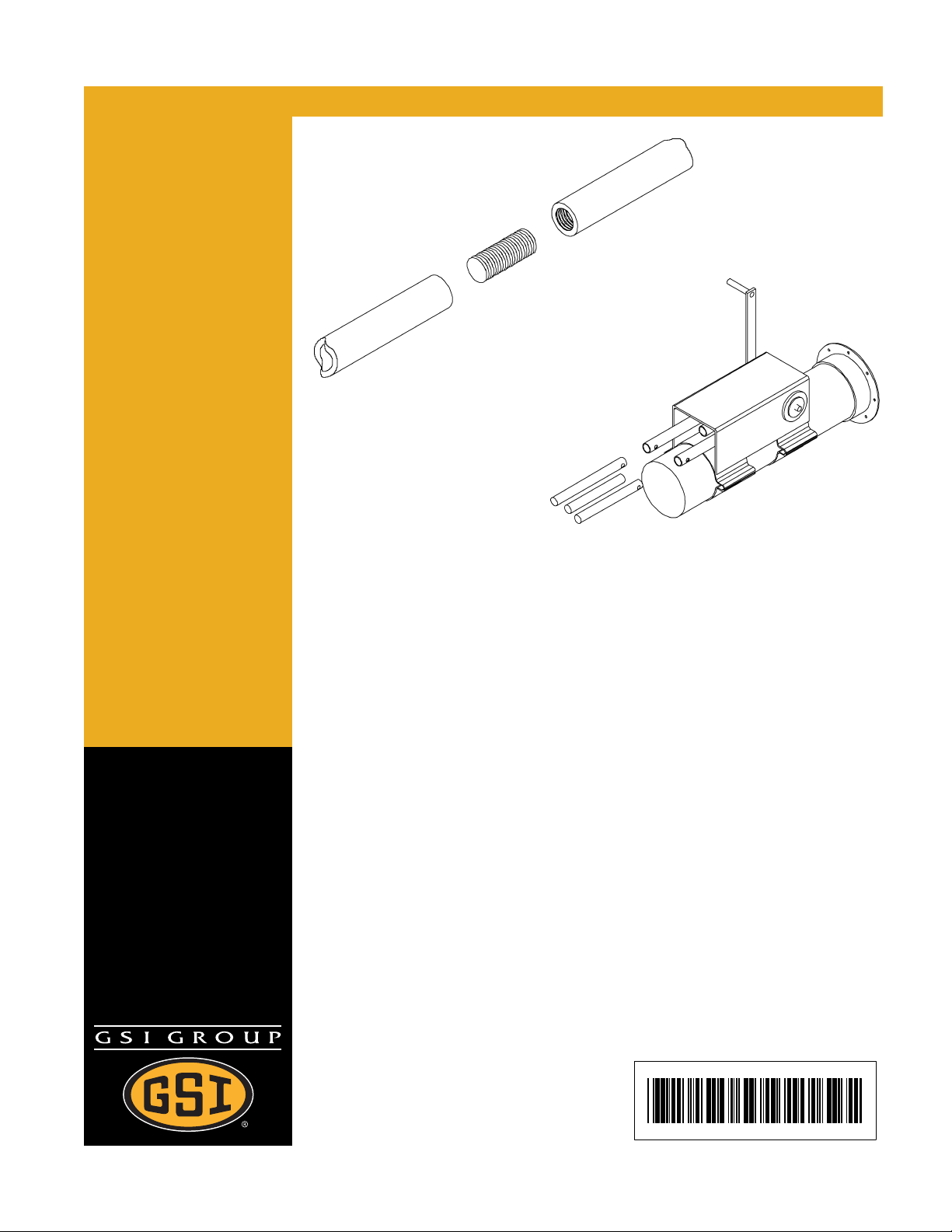
Commercial Bin Well Control
Rod Kits & Rack & Pinion
Controls
Assembly Manual
PNEG-790
Date: 05-08-07
PNEG-790
Page 2
Personnel operating or working around this equipment should read this manual. This
manual must be delivered with equipment to its owner. Failure to read this manual and
its safety instructions is a misuse of the equipment. Any misuse of the equipment may
void the warranty.
Control Rod Kits
24' - GCP24000 63' - GCP63000
27' - GCP27000 68' - 69' - GCP68000
30' - GCP30000 72' - GCP72000
33' - 34' - GCP33000 75' - GCP75000
36' - GCP36000 78' - GCP78000
37' - 39' - GCP38000 80' - GCP80000
40' - GCP40000 82' - GCP82000
42' - GCP42000 90' - GCP90000
48' - 49' - GCP48000 92' - GCP92000
54' - 55' - GCP54000 105' - GCP105000
60' - GCP60000 113' - GCP113000
120' - GCP120000
Rock & Pinion Control
8'' - GSA80110
10'' - GSA10110
12'' - GCA12110
2 Pneg - 790 Commercial Bin Well Control Rod Kits & Rack & Pinion Controls
Page 3

Table of Contents
Contents
Chapter 1 Safety .................................................................................................................................. 5
Safety Guidelines ................................................................................................................ 5
Safety Instructions ............................................................................................................... 6
Operator Qualifications ....................................................................................................... 9
Chapter 2 Safety Decals ................................................................................................................... 10
Chapter 3 Assembly ......................................................................................................................... 11
Control Rod Handle Assembly Diagram. .......................................................................... 11
Commercial Bin Control Rod Kits. ..................................................................................... 12
Control Rod Assembly. ..................................................................................................... 13
Optional Commercial Bin Well Rack & Pinion Control. ..................................................... 14
Chapter 4 Warranty ........................................................................................................................... 17
Pneg - 790 Commercial Bin Well Control Rod Kits & Rack & Pinion Controls 3
Page 4
st
SAFETY
We Replace missing guards and shields
FREE OF CHARGE!
Our equipment is built to provide many years of dependable service to our customers through
durable craftsmanship.
One of the most important aspects of our engineering is SAFETY 1
product lines. At our company -Safety is NO ACCIDENT!
That is why we have implementing its SAFETY 1
shields, safety decals or owner/operator manuals, simply contact us, or your local dealer, and
we will supply you with them FREE OF CHARGE!
While it is our main goal for our to be the world leader in auger manufacturing, it is always our
first priority to keep our customers safe.
If you need any of the above listed safety items or have safety questions, please contact the
manufacturer or your local dealer.
The GSI Group
PO Box 20
1004 E. illinois Street
Assumption, IL 62510
Ph: 1-217-226-4421
st
program. Should you ever need guards,
st
design throughout all
4 Pneg - 790 Commercial Bin Well Control Rod Kits & Rack & Pinion Controls
Page 5
T
E
Y
.
1
Safety Guidelines
This manual contains information that is important for you, the owner/operator, to know and
understand. This information relates to protecting personal safety and preventing equipment
problems. It is the responsibility of the owner/operator to inform anyone operating or working in
the area of this equipment of these safety guidelines. To help you recognize this information,
we use the symbols that are defined below. Please read the manual and pay attention to these
sections. Failure to read this manual and it’s safety instructions is a misuse of the equipment
and may lead to serious injury or death.
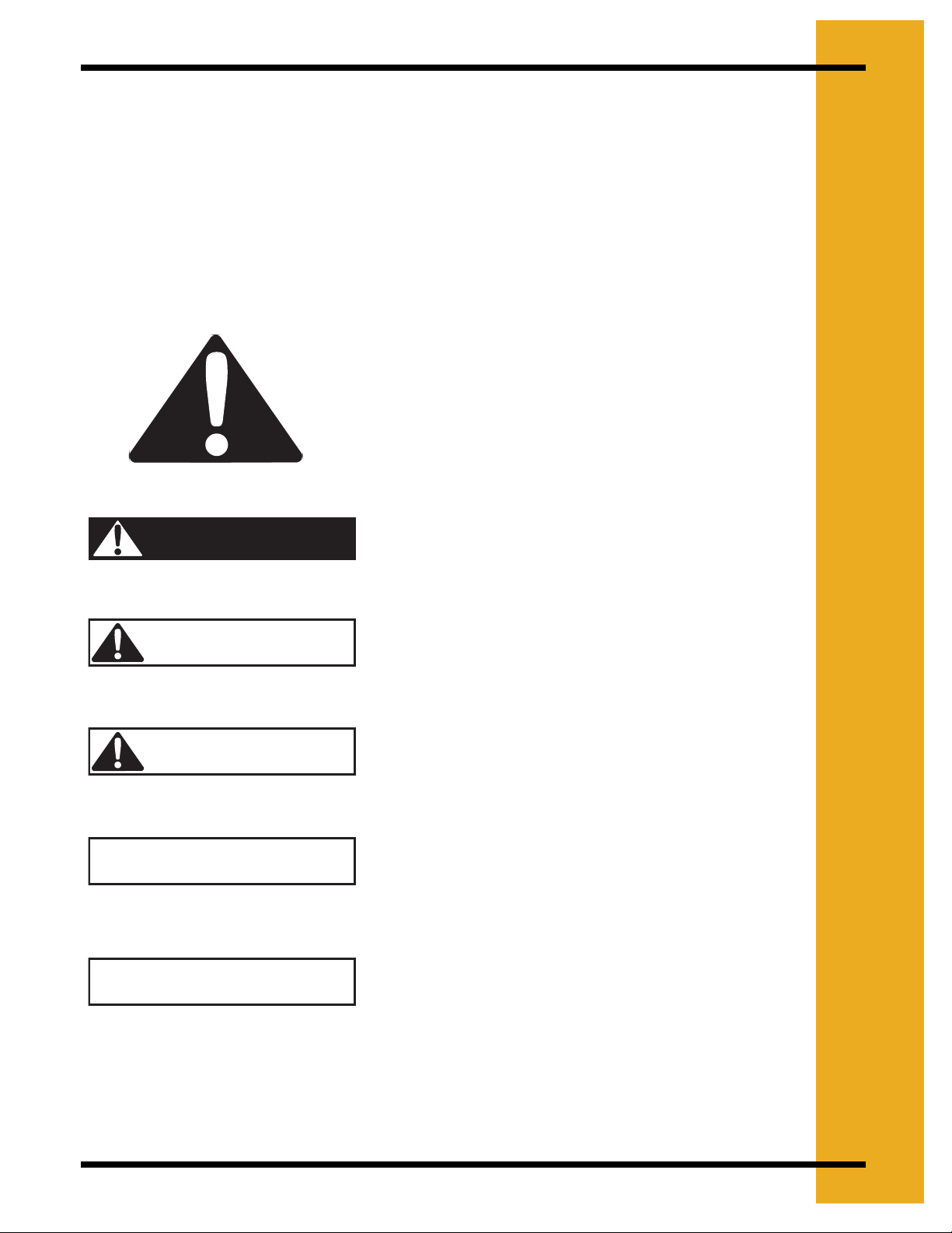
This is the safety alert symbol. It is used to alert you
to potential personal injury hazards. Obey all safety
messages that follow this symbol to avoid possible
injury or death.
F
S
A
DANGER
WARNING
CAUTION
CAUTION
NOTE
DANGER indicates an imminently hazardous situation
which, if not avoided, will result in death or serious
injury.
WARNING indicates a potentially hazardous situation which, if not avoided, could result in death or serious injury.
CAUTION indicates a potentially hazardous situation
which, if not avoided, may result in minor or moderate
injury.
CAUTION used without the safety alert symbol indicates
a potentially hazardous situation which, if not avoided,
may result in property damage.
NOTE indicates information about the equipment that
you should pay special attention to.
Pneg - 790 Commercial Bin Well Control Rod Kits & Rack & Pinion Controls 5
Page 6
1. SAFETY
Safety Instructions
GSI’s principle concern is your safety and the safety of others associated with grain handling
equipment. We want to keep you as a customer. This manual is to help you understand safe
operating procedures and some problems which may be encountered by the operator and other
personnel.
As owner and/or operator, it is your responsibility to know what requirements, hazards and
precautions exist, and to inform all personnel associated with the equipment or in the area.
Safety precautions may be required from the personnel. Avoid any alterations to the equipment.
Such alterations may produce a very dangerous situation, where SERIOUS INJURY or DEATH
may occur.
This equipment shall be installed in accordance with the current installation codes and applicable
regulations which should be carefully followed in all cases. Authorities having jurisdiction should
be consulted before installations are made.
Operate Unload Equipment Properly
Make sure ALL equipment is locked in position before operating.
NEVER start equipment until ALL persons are clear of the work area.
Use caution not to hit the auger when positioning the load.
Be sure all operators are adequately rested and prepared to perform all functions of operating
this equipment.
Untrained operators subject themselves and others to SERIOUS INJURY or DEATH. NEVER
allow untrained personnel to operate this equipment.
Keep children and other unqualified personnel out of the working area at ALL times.
NEVER allow any person intoxicated or under the influence of alcohol or drugs to operate the
equipment.
NEVER work alone. Make sure someone is nearby who is aware of the proper shutdown
sequence in the event of an accident or emergency.
ALWAYS think before acting. NEVER act impulsively around the equipment.
NEVER allow anyone inside a bin, truck or wagon which is being unloaded by an auger or
conveyor. Flowing grain can trap and suffocate in seconds.
Use ample overhead lighting after sunset to light the work area.
Keep area around intake free of obstacles such as electrical cords, blocks, etc. that might trip
workers.
Operate Unload
Equipment Safely
NEVER drive, stand or walk under the equipment.
ALWAYS lockout ALL power to the equipment when finished unloading a bin.
Be aware of pinch points. A Pinch point is a narrow area between two surfaces that is likely to
trap or catch objects and so is a potential safety hazard.
6 Pneg - 790 Commercial Bin Well Control Rod Kits & Rack & Pinion Controls
Page 7

Follow Safety Instructions
Carefully read all safety messages in this manual and
safety signs on your equipment. Keep signs in good
condition. Replace missing or damaged safety signs. Be
sure new equipment components and repair parts
include the current safety signs. Replacement safety
signs are available from the manufacturer.
Learn how to operate the machine and how to use controls
properly. Do not let anyone operate without instruction.
Keep your machinery in proper working condition.
Unauthorized modifications to the machine may impair
the function and/or safety and affect machine life.
If you do not understand any part of this manual and need
assistance, contact your dealer.
Keep Hands Away from Moving Parts
Keep hands and feet away from auger intake and other moving
parts. Rotating auger can sever a person's limbs or even kill.
Keep hair, loose clothing, and shoestrings away from rotating
and moving parts. NEVER wear loose fitting clothing when
working around augers.
ALWAYS turn off and lock out all power sources before servicing
equipment.
ALWAYS keep belt and chain guards in place during operation.
NEVER attempt to assist machinery operation or to remove trash
from equipment while in operation.
1. SAFETY
Read and Understand
Manual
Rotating Auger
Operate Motor Properly
In an emergency, shut down the power source.
Turn off and lock out all power sources before performing any
maintenance.
Do not operate electric motor equipped units until motors are
properly grounded.
Disconnect power on electrical driven units before resetting
motor overloads.
Do not repetitively stop and start the drive in order to free a
plugged condition. Jogging the drive in this type of condition
can damage the auger and/or drive components.
Practice Safe Maintenance
Understand service procedures before doing work. Keep area
clean and dry.
Never lubricate, service, or adjust machine while it is in
operation. Keep hands, feet, and clothing from rotating shafts,
screws, belts, or other moving equipment.
Keep all parts in good condition and properly installed. Fix
damage immediately. Replace worn or broken parts. Remove
any build up grease, oil, or debris.
Electrical Shock
Hazard
Maintain Equipment
and Work Area
Pneg - 790 Commercial Bin Well Control Rod Kits & Rack & Pinion Controls 7
Page 8

1. SAFETY
Wear Protective Clothing
Wear close fitting clothing and safety equipment
appropriate to the job.
Safety glasses should be worn at all times to
protect eyes from debris.
Wear gloves to protect your hands from sharp
edges on plastic or steel parts.
Use a respirator to prevent breathing potentially
toxic fumes and dust..
Wear hard hat and steel toe boots to help protect
your head and toes from falling debris.
Eye Production
Gloves
Steel Toe
Boots
Remove all jewelry.
Tuck in any loose or dangling shoe strings.
Long hair should be tied up and back.
Prepare for Emergencies
Be prepared if fire starts.
Keep a first aid kit and fire extinguisher handy.
Keep emergency numbers for doctors, ambulance
service, hospital, and fire department near your
telephone.
Respirator
Hard Hat
Keep Emergency Equipment
Quickly Accessible
8 Pneg - 790 Commercial Bin Well Control Rod Kits & Rack & Pinion Controls
Page 9

1. SAFETY
Operator Qualifications
1. The User/Operator must be competent and experienced to operate auger equipment.
Anyone who works with or around augers must have good common sense in order to be
qualified. These persons must also know and meet all other qualifications, such as:
a. Any person who has not read and/or does not understand all operation and safety
procedures is not qualified to operate any auger systems.
b. Certain regulations apply to personnel operating power machinery. Personnel under the
age of 18 years may not operate power machinery, including augers. It is your
responsibility, as owner and/or supervisor, to know what these regulations are in your
area or situation.
c. Unqualified or incompetent persons are to remain out of the work area.
d. O.S.H.A. (Occupational Safety & Health Administration) regulations state: “At the time of
initial assignment and at least annually thereafter, the employer shall instruct every
employee in the safe operation and servicing of all equipment with which the employee
is, or will be involved”. (Federal Occupational Safety & Health Standards for Agriculture.
Subpart D, Section 19287.57) (a) (6).
2. As a requirement of O.S.H.A, it is necessary for the employer to train the employee in the
safe operating and safety procedures for this auger. We included this sign-off sheet for
your convenience and personal record keeping. All unqualified persons are to stay out of
the work area at all times. It is strongly recommended that another qualified person who
knows the shutdown procedure is in the area in the event of an emergency. A person who
has not read this manual and understands all operating and safety instructions is not
qualified to operate the machine.
Date Employer’s Signature Employee Signature
1
2
3
4
5
6
7
8
9
10
11
12
13
14
15
Pneg - 790 Commercial Bin Well Control Rod Kits & Rack & Pinion Controls 9
Page 10

2. SAFETY DECALS
ATTENTION: The decal shown below should be present on the outside of the outside of the door
cover of the two ring, 24" porthole door cover and roof manway cover. If a decal has been
damaged or is missing in any of these locations contact the manufacturer for a free replacement
decal.
DECALS
P.O. BOX 602
1004 East ILLinois Street
Assumption, IL. 62510-00020
(217)-226-4421
Rotating flighting will
kill or dismember.
Flowing material will
trap and suffocate.
Crusted material will
collapse and suffocate.
Keep clear of all augers.
DO NOT ENTER this bin!
If you must enter the bin:
1. Shut off and lock out all power.
2. Use a safety harness and safety line.
3. Station another person outside the bin.
4. Avoid the center of the bin.
5. Wear proper breathing equipment or respirator.
Failure to heed these
warnings will result in
serious injury or death.
DC-GBC-1A
10 Pneg - 790 Commercial Bin Well Control Rod Kits & Rack & Pinion Controls
Page 11

Control Rod Handle Assembly Diagram.
M
S
E
S
.
A
2
5/16'' Nut
5/16'' Lockwasher
5/16'' Flatwasher
Gate Control Clamp
B
L
Y
5/16'' x 2'' Long Hex Head Bolt
1.2'' Control Rod
5/16'' Hex Nut
Control Rod
5/16'' x 1-3/4'' Roll Pin
5/16'' x 3/4'' Carriage Bolt
Note: All 5/16'' Nuts must be installed so that the 5/16'' x 1-3/4'' long roll pin is secured.
Figure 2A
Pneg - 790 Commercial Bin Well Control Rod Kits & Rack & Pinion Controls 11
Page 12

2. ASSEMBLY
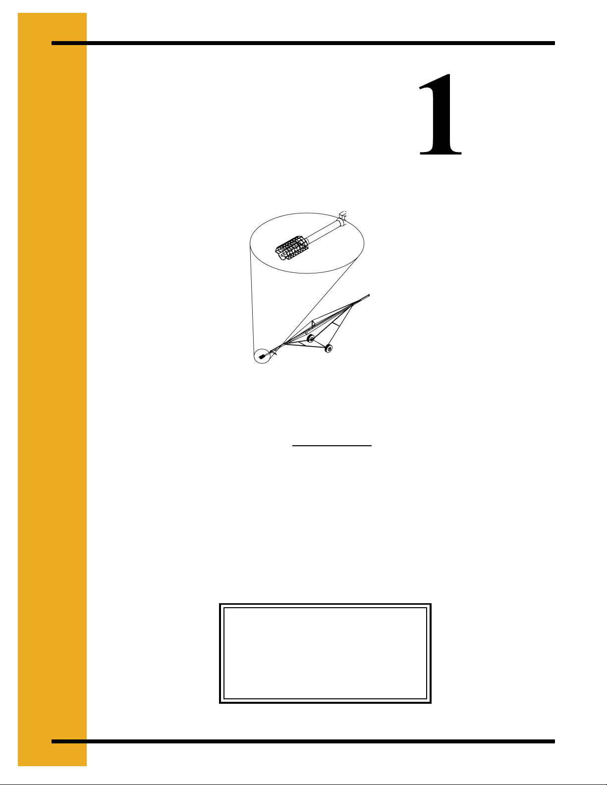
Commercial Bin Control Rod Kits.
Commercial Bin Control Rod Kit is used for opening and closing the
bin well control gates from outside the bin.
The optional Rack & Pinion Control can be used to make the job easier. Contact
your distributor for more information.
The Commercial Bin Control Rod Kit can be used on 24' - 75' (7.32 m - 22.86 m)
diameter bins.
The Commercial Bin Control Rod Kit comes with three (3) control rods to be used
with a minimum of two (2) Intermediate Bin Wells and the Center Bin Well.
Two (2) or more rod sections are used for larger diameter bins. The rod sections
are connected with an Internal Threaded Coupler.
1. Use the following illustration Figure 2B and the chart on Page 13 to determine the
necessary pipe lengths.
Bin Wall
Rack & Pinion
Control
A. Outer Intermediate
Bin Well Control Rod
B. Inner Intermediate Bin
Well Control Rod
Figure 2B
C. Center Bin Well Control Rod
Center Well
D
12 Pneg - 790 Commercial Bin Well Control Rod Kits & Rack & Pinion Controls
Page 13

2. ASSEMBLY
Length of Control Rods
ABC
D
Spacing
Bin
Diameter
24' 31 - 1/2" 2 11' 11 - 1/2" 11' 11 - 1/2" 8' 2 - 1/2" 8' 2 - 1/2" 3' 4 - 1/2" 3' 4 - 1/2"
27' 38 - 1/2" 2 13' 5 - 1/2" 13' 5 - 1/2" 9' 1 - 1/2" 9' 1 - 1/2" 3' 8 - 1/2" 3' 8 - 1/2"
30' 45 - 1/2" 2 14' 11 - 1/2" 14' 11 - 1/2" 10' 1/2" 10' 1/2" 4' 1/2" 4' 1/2"
34' 55 - 1/2" 2 16' 11 - 1/2" 16' 11 - 1/2" 11' 2 - 1/2" 11' 2 - 1/2" 4' 4 - 1/2" 4' 4 - 1/2"
36' 35 - 1/2" 3 17' 11 - 1/2" 17' 11 - 1/2" 13' 10 - 1/2" 13' 10 - 1/2" 8' 8 - 1/2" 8' 8 - 1/2"
39' 40 - 1/2" 3 19' 5 - 1/2" 19' 5 - 1/2" 14' 11 - 1/2" 14' 11 - 1/2" 9' 4 - 1/2" 9' 4 - 1/2"
40' 42 - 1/2" 3 19' 11 - 1/2" 19' 11 - 1/2" 15' 3 - 1/2" 15' 3 - 1/2" 9' 6 - 1/2" 9' 6 - 1/2"
42' 29 - 1/2" 4 20' 11 - 1/2" 20' 11 - 1/2" 17' 4 - 1/2" 17' 4 - 1/2" 8' 1/2" 8' 1/2"
49' 38 - 1/2" 4 24' 5 - 1/2" 21' & 3' 5 - 1/2" 20' 1 - 1/2" 20' 1 - 1/2" 9' 4 - 1/2" 9' 4 - 1/2"
55' 46 - 1/2" 4 27' 5 - 1/2" 21' & 6' 5 - 1/2" 22' 5 - 1/2" 21' & 1' 5 - 1/2" 10' 9 - 1/2" 10' 9 - 1/2"
60' 53 - 1/2" 4 29' 11 - 1/2" 21' & 8' 11 - 1/2" 24' 4 - 1/2" 21' & 3' 4 - 1/2" 9' 1" 9' 1"
63' 57 - 1/2" 4 31' 5 - 1/2" 21' & 10' 5 - 1/2" 25' 6 - 1/2" 21' & 4' 6 - 1/2" 13' 9 - 1/2" 13' 9 - 1/2"
68' 65 - 1/2" 4 34' 5 - 1/2" 21' & 13' 5 - 1/2" 27' 10 - 1/2" 21' & 6' 10 - 1/2" 12' 6 - 1/2" 12' 6 - 1/2"
72' 69 - 1/2" 4 35' 11 - 1/2" 21' & 14' 11 - 1/2" 29' 1/2" 21' & 8' 1/2" 13' 1/2" 13' 1/2"
75' 73 - 1/2" 4 36' 5 - 1/2" 21' & 16' 5 - 1/2" 30' 2 - 1/2" 21' & 9' 2 - 1/2" 13' 6 - 1/2" 13' 6 - 1/2"
Between
Intermediate
Bin Wells
Number of
Intermediate
Bin Wells
Assembly
Center Well Inner Intermediate Wells
Length
Length of
Sections
Assembly
Length
Length of
Sections
Outer Intermediate
Wells
Assembly
Length
Length of
Sections
The labels “A”, “B”, “C” and “D” correlate with the same labels in Figure 2B on page 6.
Control Rod Assembly.
Internal Threaded
Coupler
Control Rod
Sections
Figure 2C
1. Screw two (2) 1/2'' rod sections together using an Internal Threaded Coupler, as
shown in Figure 2D .
Pneg - 790 Commercial Bin Well Control Rod Kits & Rack & Pinion Controls 13
Page 14

2. ASSEMBLY
Optional Commercial Bin Well Rack & Pinion Control.
F The optional Rack & Pinion Control can be used with up to three (3) sets
of controls.
The center controller is used to open and close the Center Bin Well.
The two (2) other controls are used to open and close the Intermediate Bin Wells.
Control Rod Kits can be purchased with the rods pre-cut to be ready for use. See
your distributor for more information.
Bin
Wall
Rack &
pinion
Control
Outer Intermediate Bin
Well Control Rod
Inner Intermediate
Bin Well Control Rod
Figure 2D
Center Bin Well Control Rod
Center Well
1. Place the Rack & Pinion Control on the Unload Tube, positioning the control rod sleeves
toward the bin.
2. Turn the control rod sleeves into the housing.
3. Move the Rack & Pinion Control as close as possible to the unload tube flange.
a. Be sure to leave room to reach the flange bolts, especially if frequently installing and
removing the Powerhead.
4. Tighten the Rack & Pinion Control in place by using the half bands and 5/1'' x 1'' bolts and
nuts.
5. Close the Center Bin Well control gate.
6. Turn the control sleeve assembly toward the bin as far as possible.
7. Measure from the Center Bin Well control gate to the hole in the center control rod sleeve.
8. Add 2'' (5.08 cm) to the measurement from Step 7.
9. Use the total from Step 8 and cut a control rod of that length.
10. Attach the control rod to the Center Bin Well control gate.
14 Pneg - 790 Commercial Bin Well Control Rod Kits & Rack & Pinion Controls
Page 15

2. ASSEMBLY
11. Attach the control rod to the Rack & Pinion Control.
12. Bolt the control rod to the control rod sleeve, using a roll pin or 5/16'' bolt and nut.
a. Available for purchase are Control Rod Guides. Control Rod Guides are
necessary when not using the recommended number of Intermediate
Bin Wells or when there is a larger-than-normal distance between
the bin wells.
b. The control rods MUST be supported. Unsupported control rods can sag causing
misalignment which will cause the controls to grind. This is a misuse of the equipment.
Any misuse of the equipment may void the warranty.
13. Make sure the Intermediate Bin Wells are properly distanced.
14. Make sure the Intermediate Bin Well control gates open toward the center of the bin.
a. The control rods must be pulled to open the bin well control gates.
15. Close all control gates.
16. Know which control rod opens each well.
a. One control rod should control the Center Bin Well.
b. One control rod should control the Intermediate Bin Wells nearest to the
center Bin wall.
c. The control rod should control the Intermediate Bin Wells nearest to the bin wall.
d. The control rods for the Intermediate Bin Wells should each control an even
number of bin wells.
17. Measure from the Intermediate Bin Well control gates clamps to the holes in their
respective control rod sleeves.
18. Add 2'' (5.08 cm) to the measurement from Step 17.
19. Cut a control rod the length of the total determined Step 18.
20. Attach the control rod to the Intermediate Bin Wells it will control.
21. Attach the opposite end to the Rack & Pinion Control.
22. Secure the control rod to the control rod sleeve, using a roll pin or a 5/16'' bolt and nut.
Pneg - 790 Commercial Bin Well Control Rod Kits & Rack & Pinion Controls 15
Page 16

2. ASSEMBLY
Figure 2E
Operation of the Optional Commercial Bin Well Rack & Pinion Control.
1. Move all the control rod sleeves toward the bin as for as possible.
2. Check to see that all bin well control gates are properly closed.
3. Open the Center Bin Well to the proper flow rate.
a. The control rods must be pulled to open the bin well control gates.
4. NEVER open the Intermediate Bin Wells until grain is no longer flowing from the Center Bin
Well.
a. When it is time to open the Intermediate Bin Wells control gates, they can be opened
one at a time, or all at once.
Be sure the Center Bin Well is also open when the Intermediate Bin Wells
are open.
5. If using the Direct Gear Drive Bin Sweep Auger, open the Center Bin Well control gate as
far as possible, by removing the pin from the center control rod. Then place the control rod
in the CLOSED position, and insert the pin in the second (2nd) hole of the center control
rod.
6. To close the opening, perform Step 5 in reverse.
16 Pneg - 790 Commercial Bin Well Control Rod Kits & Rack & Pinion Controls
Page 17

Limited Warranty
The GSI Group, LLC. (“GSI”) warrants products which it manufactures to be free of defects in materials
and workmanship under normal usage and conditions for a period of 12 months after sale to the original
end-user or if a foreign sale, 14 months from arrival at port of discharge, whichever is earlier. The enduser’s sole remedy (and GSI’s only obligation) is to repair or replace, at GSI’s option and expense,
products that in GSI’s judgment, contain a material defect in materials or workmanship. Expenses
incurred by or on behalf of the end-user without prior written authorization from the GSI Warranty Group
shall be the sole responsibility of the end-user.
Warranty Extensions: The Limited Warranty period is extended for the following products:
Product Warranty Period
AP Fans and
Flooring
Cumberland
Feeding/Watering
Systems
Grain Systems
Grain Systems
Farm Fans
Zimmerman
Performer Series Direct Drive
Fan Motor
All Fiberglass Housings Lifetime
All Fiberglass Propellers Lifetime
Feeder System Pan Assemblies 5 Years **
Feed Tubes (1.75" & 2.00") 10 Years *
Centerless Augers 10 Years *
Watering Nipples 10 Years *
Grain Bin Structural Design 5 Years
Portable & Tower Dryers 2 Years
Portable & Tower Dryer Frames
and Internal Infrastructure †
3 Years
5 Years
GSI further warrants that the portable and tower dryer frame and basket, excluding all auger and auger
drive components, shall be free from defects in materials for a period of time beginning on the twelfth (12
month from the date of purchase and continuing until the sixtieth (60
th
) month from the date of purchase
* Warranty prorated from list price:
0 to 3 years – no cost to end-user
3 to 5 years – end-user pays 25%
5 to 7 years – end-user pays 50%
7 to 10 years – end user pays 75%
** Warranty prorated from list price:
0 to 3 years – no cost to end-user
3 to 5 years – end-user pays 50%
† Motors, burner components and
moving parts not included. Portable
Dryer screens included. Tower Dryer
screens not included.
th
)
(extended warranty period). During the extended warranty period, GSI will replace the frame or basket
components that prove to be defective under normal conditions of use without charge, excluding the labor,
transportation, and/or shipping costs incurred in the performance of this extended warranty.
Conditions and Limitations:
THERE ARE NO WARRANTIES THAT EXTEND BEYOND THE LIMITED WARRANTY DESCRIPTION
SET FORTH ABOVE. SPECIFICALLY, GSI MAKES NO FURTHER WARRANTY OF ANY KIND,
EXPRESS OR IMPLIED, INCLUDING, WITHOUT LIMITATION, WARRANTIES OF MERCHANTABILITY
OR FITNESS FOR A PARTICULAR PURPOSE OR USE IN CONNECTION WITH: (i) PRODUCT
MANUFACTURED OR SOLD BY GSI OR (ii) ANY ADVICE, INSTRUCTION, RECOMMENDATION OR
SUGGESTION PROVIDED BY AN AGENT, REPRESENTATIVE OR EMPLOYEE OF GSI REGARDING
OR RELATED TO THE CONFIGURATION, INSTALLATION, LAYOUT, SUITABILITY FOR A PARTICULAR
PURPOSE, OR DESIGN OF SUCH PRODUCTS.
GSI shall not be liable for any direct, indirect, incidental or consequential damages, including, without
limitation, loss of anticipated profits or benefits. The sole and exclusive remedy is set forth in the Limited
Warranty, which shall not exceed the amount paid for the product purchased. This warranty is not
transferable and applies only to the original end-user. GSI shall have no obligation or responsibility for any
representations or warranties made by or on behalf of any dealer, agent or distributor.
GSI assumes no responsibility for claims resulting from construction defects or unauthorized modifications
to products which it manufactured. Modifications to products not specifically delineated in the manual
accompanying the equipment at initial sale will void the Limited Warranty.
This Limited Warranty shall not extend to products or parts which have been damaged by negligent use,
misuse, alteration, accident or which have been improperly/inadequately maintained. This Limited Warranty
extends solely to products manufactured by GSI.
Prior to installation, the end-user has the responsibility to comply with federal, state and local codes which
apply to the location and installation of products manufactured or sold by GSI.
9101239_1_CR_rev7.DOC (revised July 2009)
Page 18

This equipment shall be installed in accordance with
the current installation codes and applicable
regulations which should be carefully followed in all
cases. Authorities having jurisdiction should be
consulted before installations are made.
Internet: http://www.grainsystems.com
Copyright © 2007 by the GSI Group
Printed in the USA
GSI Group, Inc.
1004 E. Illinois St.
Assumption, IL 62510-0020
Phone: 1-217-226-4421
Fax: 1-217-226-4420
 Loading...