

Page 1

Owner’s Manual
Manual # PNEG-780
5-17-07
BIN STAIRS
& PLATFORM
ASSEMBLY
ASSEMBL Y MANUAL
PNEG-780
Page 2

Bin Stairs and Platform AssemblyBin Stairs and Platform Assembly
Bin Stairs and Platform Assembly
Bin Stairs and Platform AssemblyBin Stairs and Platform Assembly
2
Page 3

Bin Stairs and Platform AssemblyBin Stairs and Platform Assembly
Bin Stairs and Platform Assembly
Bin Stairs and Platform AssemblyBin Stairs and Platform Assembly
Table of Contents
Safety First..............................................................................................3
Positioning Stairs and Platform..........................................................4
Platform Assembly.....................................................................5
Stair- Top Section Assembly............................................................6-8
Step Preassembly.....................................................................7
Step to Horizontal Bar Attachment......................................................7
Tie Strap Attachment..........................................................7
Handrail Post Attachment.............................................................8
Platform to Step Splice............................................................8
4.00” Standard Section.................................................................9
Handrail Installation....................................................................10
Top Handrail.....................................................................10
Intermediate Handrail................................................................10
Table of ContentsTable of Contents
Table of Contents
Table of ContentsTable of Contents
3
Page 4

Safety FirstSafety First
Safety First
Safety FirstSafety First
Bin Stairs and Platform AssemblyBin Stairs and Platform Assembly
Bin Stairs and Platform Assembly
Bin Stairs and Platform AssemblyBin Stairs and Platform Assembly
SAFETY FIRST
General Safety Statements
The GSI Group Inc’ s Principal concern is your
safety and the safety of others associated with grain
handling equipment. W e want to keep you as a customer . This manual is to help you understand safe
operating procedures and some problems which may
be encountered by the operator and other personnel.
As owner and/or operator, it is your responsibility to know what requirements, hazards and precautions exist and inform all personnel associated with,
or in the area of the equipment. Safety precautions
may be required from the personnel. Avoid any alteration to the equipment. Such alterations may produce a very dangerous situation, where serious injury
or death may occur.
BE ALERT!
Danger!
Personnel operating or working around electrical
equipment should read this manual. This manual
must be delivered with equipment to its owner.
Failure to read this manual and its safety instructions is a misuse of the equipment.
This product is intended for agricultural use to gain
access to grain bins only. Any other use is a misuse
of the product!
ATTENTION !
SAFETY ALERT
SYMBOL
The symbol shown is used to call your attention to
instructions concerning your personal safety.
W atch for this symbol; as it points out important
safety precautions. It means “ATTENTION,”
WARNING,” “CAUTION,” and “DANGER.”
Read the message that follows and be cautious to
the possibility of personal injury or death.
This product has sharp edges!
These sharp edges may cause serious injury. T o
avoid injury handle sharp edges with caution and
use proper protective clothing and equipment at
all times.
4
Page 5
Bin Stairs and Platform AssemblyBin Stairs and Platform Assembly
Bin Stairs and Platform Assembly
Bin Stairs and Platform AssemblyBin Stairs and Platform Assembly
Positioning Stairs & Platform
Positioning Stair & PlatformPositioning Stair & Platform
Positioning Stair & Platform
Positioning Stair & PlatformPositioning Stair & Platform
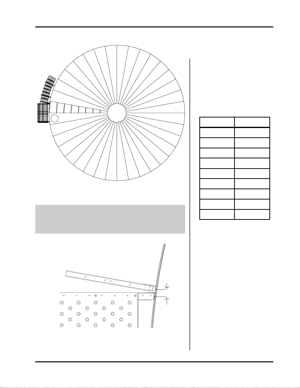
Position the roof ladder and manhole
to allow for platform placement.
Refer to the table on this page to determine where stairs will end. Position the end of the stairs to avoid augers, doors, fans, and control boxes.
Spaces around Bin
4.00” Corrugation
Rings Spaces
414
518
622
Figure 1: Orientation of Platform in relation to the manhole & roof
ladder.
Note: Stairs may be assembled in either a clockwise or counter
clockwise direction around the Bin. However, clockwise is
recommended.
2”
726
830
934
10 38
11 42
12 46
Once you determine the platform location, position the platform wall
bracket 2” from the horizontal seam
bolt where the stairs will begin. Field
drill the bolt hole on the horizontal
seam and 4-5 more from top to bottom on the wall bracket and secure.
Use 5/16” x 1 1/4” bolt to attach wall
bracket.
Firgure 2: Bracket Distance from Step Bracket.
Note: The top of the wall bracket
should line up with the corrugation at the eave.
5
Page 6

Platform AssemblyPlatform Assembly
Platform Assembly
Platform AssemblyPlatform Assembly
Platform Assembly
When attaching the sidewall access platform to the
tank wall, vertical wall brackets need to be mounted
to the bin wall with 5/16” x 3/4” bin bolts (see Fig.
3). To insure the proper placement of the second
wall bracket, preassemble platform support (see Fig.
4) and mark the hole positions for drilling. Field drill
and assemble the platform support with 5/16” truss
head bolts. Now , proceed to the platform floor and
floor splice. Align holes on platform floor with the
holes on platform supports and bolt together using
5/16” x 3/4” truss head bolts and nuts. Be sure and
attach platform toe plate at the same time you attach
the platform floor (see Fig.6).
Bin Stairs and Platform AssemblyBin Stairs and Platform Assembly
Bin Stairs and Platform Assembly
Bin Stairs and Platform AssemblyBin Stairs and Platform Assembly
Figure 3: Wall Brackets to Bin W all.
(2) Wall Bracket
LDR-4092
LS-6623 (2)
Platform Support
TDP-5005 (Lt Blue/Black)
Floor Brace (3)
Diagonal Support Angle (2)
LDR-4142
Figure 4: Platform Support Assembly
TDP-5002 (Pink/Black)
30” Hand Rail
TDP-5000 (Brown)
59” Hand Rail
TDP-5011
Platform
Toe Plate
TDP-5010 Platform
Splice Plate
TDP-5006
Platform Floor
Figure 5: Platform Assembly
6
Page 7

Bin Stairs and Platform AssemblyBin Stairs and Platform Assembly
Bin Stairs and Platform Assembly
Bin Stairs and Platform AssemblyBin Stairs and Platform Assembly
Stair - Top Section Assembly
LDR-4092
Wall Bracket
(I) LDR-4082
Stair Wall Bracket
(II)LDR-4083
Horizontal Bar
Bracket
(III) LDR-4084
Knee Brace
Stair - Top Section AssemblyStair - Top Section Assembly
Stair - Top Section Assembly
Stair - Top Section AssemblyStair - Top Section Assembly
LDR-4142
Diagonal Support Angle
Figure 6: Stair - T op Section Assembly
I. The stair wall bracket (LDR-4082) should be
placed on a horizontal seam and bolted vertically .
The vertical location must be field drilled to match
up with platform location. Use 5/16” x 1 1/4”
bolt to secure LDR-4082 to the sidewall. Field
drill 3 more holes and attach the bracket.
II. Using the two end holes of horizontal step bracket
attach it to LDR-4082 with (2) 3/8” x 1”flanged
head bolts and nuts.
III. Using the same bolts and nuts as step II connect
the knee brace (LDR-4084) to LDR-4083 and
LDR-4082.
IV . Continue to raise bin adding sidewall sheets until
the top hole of the next sidewall bracket can be
attached to a horizontal seam. Each step will
cover 9 3/8” on the horizontal seam. Two steps
will be added before the next brace assembly can
be mounted. There should be a distance of 18 3/
4” along the horizontal seam between brackets.
Fasten the lower end of the bracket to the seam
with a seam bolt. You will need to field drill
extra holes (2) as needed to finish fastening
the bracket to the seam. (Use 5/16” x 1 1/4”
Bin Bolts).
V. Complete the second wall support assembly as
previously instructed in step II and III
7
Page 8

Stair Top Section AssemblyStair Top Section Assembly
Stair Top Section Assembly
Stair Top Section AssemblyStair Top Section Assembly
Bin Stairs and Platform AssemblyBin Stairs and Platform Assembly
Bin Stairs and Platform Assembly
Bin Stairs and Platform AssemblyBin Stairs and Platform Assembly
Step Preassembly
Figure 7: Step Assembly
LDR-4079 -- Step
LDR-4080 -- Right End
LDR-4081 -- Left End
Preassemble ends to step with 5/16” truss head bolts.
Put all bolts in the bottom of the step and install the
bottom two bolts on the back of the step and tighten.
Step to Horizontal Bar Attachment
Attach step assembly to the top horizontal bracket
with two 5/16” x 3/4” T russ head bolts. Use the outer
set of holes in the horizontal bracket. Attach another
step to the lower horizontal bracket. Maneuver the
next step in between the others and attach the top
side tabs to the outside of the upper steps with truss
head bolts see Figure 8. Attach lower step tabs in
the same manner.
Tie Strap Attachment
Attach the steps to each other with the tie straps (LDR-
4090). Use 5/16 x 3/4” truss head bolts and nuts to
attach the strap to the holes provided on the ends of
the step. Align the step slots and level the steps before tightening. The steps will align to curvature and
wall brackets. When all the parts of the top section
are in place tighten all the bolts.
5/16” x 3/4”
Truss head
bolt and nut
Figure 9: Brace Strap Connection
Attachment
Tab
Tie Strap
(LDR-4090)
T op S tair Assembly
5/16 x 3/4” Truss head bolts
Horizontal
Bracket
Figure 8: Horizontal Bracket to Step
8
Figure 10: T op Stair Assembly
Page 9

Bin Stairs and Platform AssemblyBin Stairs and Platform Assembly
Bin Stairs and Platform Assembly
Bin Stairs and Platform AssemblyBin Stairs and Platform Assembly
Handrail Post Attachment
Handrail Post
(LDR-4085)
(2) 3/8” x 1” Flange
head bolts and nuts.
Stair - Top Section AssemblyStair - Top Section Assembly
Stair - Top Section Assembly
Stair - Top Section AssemblyStair - Top Section Assembly
The handrail post (LDR-4085) connects
to the end of the horizontal wall bracket
with (2) 3/8” x 1” Flange head bolts and
nuts. Tighten the bolts and move on to the
next section. The handrail will be installed
after all stair sections are on the tank. (See
figure 10 on page 7 for a detailed drawing
of the first few steps and the hand railing.)
Figure 11: Handrail Post Connection
Cut out notches to fit
around handrail posts.
Platform to Step Splice
Platform Splice
TDP-5010
Use platform splice (TDP-5010) to cover
the gap between the platform and the stair
section. Since the gap changes with bin
diameter, field drilling and cutting are required for proper placement of the splice.
The attachment tabs on the top of the step
may need to be trimmed to allow fit (refer
to figure 9 on page 7). The splice will also
need to be notched to fit around the handrail post. Secure to the step and platform
with truss head bolts and nuts.
Figure 12: Platform Stair Splice Connection
9
Page 10

4.00” Standard Section4.00” Standard Section
4.00” Standard Section
4.00” Standard Section4.00” Standard Section
4.00” Standard Section
Continue raising the bin until the next wall
bracket can be attached to the wall 3
spaces (2.66” Corrugation) or 4 spaces
(4.00” Corrugation) along the horizontal
seam. Bolt the rest of the assembly in place
and field drill to secure. Place a step over
the wall bracket and secure. Hang the three
steps between brackets to finish the section. Align steps level with tie straps and
tighten section. Add the handrail post and
continue adding sections.
Bin Stairs and Platform AssemblyBin Stairs and Platform Assembly
Bin Stairs and Platform Assembly
Bin Stairs and Platform AssemblyBin Stairs and Platform Assembly
4.00” Corrugation
Standard Section
The bottom wall bracket will need to be
field drilled in order to attach the last horizontal bracket. The top of the horizontal
bracket should be a distance of 11” up
from the base of the tank. Attach the bottom step as previously directed. The front
lip of the bottom step may need to be
trimmed off to allow fitup. Add the two
other steps, level and tighten all bolts and
tie straps. Install the bottom handrail post.
Figure 13: 4.00” Corrugation Standard Section
Bottom Section
Wall Bracket to
Horizontal Bracket
Attachment
A distance of 11” must be measured
from the top of the horizontal bracket
to the base of the tank.
10
Figure 14: Last Step
Page 11

Bin Stairs and Platform AssemblyBin Stairs and Platform Assembly
Bin Stairs and Platform Assembly
Bin Stairs and Platform AssemblyBin Stairs and Platform Assembly
Handrail Installation
5/16” x 1 1/4”
Bolt and Nut
Handrail InstallationHandrail Installation
Handrail Installation
Handrail InstallationHandrail Installation
T op Handrail Installation
Start at the top handrail post and align the
bottom slot with the second post, mark
top post location. T rim off the narrow end
and drill for top connection. Connect with
5/16” x 1 1/4” bolt and nut. Slide the next
narrow end into the upper wide end of the
next rail. Align the slots and attach to post
with 5/16” x 1 1/4” bolt.
Note: Keep post plumb as you tighten
the bolt.
Figure15a: Handrail Connection
5/16” x 1 1/4”
Bolt and Nut
Figure15b: Handrail Connection
Continue down the stairs installing handrail sections. Extra force maybe needed
to curve the handrail for attachment to the
post. W ith smaller diameter tanks the bottom section of the handrail will require a
field drilled hole for the attachment to the
last post.
ATTENTION!
P A Y CLOSE A TTENTION
TO SHARP EDGES AND
GRIND SMOOTH ANY SHARP
POINTS. SHARP EDGES CAN
CAUSE SERIOUS INJURY!
5/16” x 1 1/4”
bin bolt and nut
Figure 16: Intermediate Handrail
Intermediate Handrail
After installing top handrail bolt the intermediate handrail in place. The handrail
section consists of a large tube and a small
telescoping tube. The large tube is located
on top. Bolt the rail in place with a 5/16”
x 1 1/4” bin bolt and nut. Continue up the
steps adding the handrail. The top middle
handrail section will need to be shortened
to fit and to complete the installation.
11
Page 12

NOTES
Bin Stairs and Platform AssemblyBin Stairs and Platform Assembly
Bin Stairs and Platform Assembly
Bin Stairs and Platform AssemblyBin Stairs and Platform Assembly
12
Page 13

Bin Stairs and Platform AssemblyBin Stairs and Platform Assembly
Bin Stairs and Platform Assembly
Bin Stairs and Platform AssemblyBin Stairs and Platform Assembly
WarrantyWarranty
Warranty
WarrantyWarranty
The GSI Group, Inc. Warranty
THE GSI GROUP, INC. (“GSI”) WARRANTS ALL PRODUCTS WHICH IT MANUFACTURES TO
BE FREE OF DEFECTS IN MATERIAL AND WORKMANSHIP UNDER NORMAL USAGE AND
CONDITIONS FOR A PERIOD OF 12 MONTHS AFTER RETAIL SALE TO THE ORIGINAL END
USER. THE PURCHASER’S SOLE REMEDY AND GSI’S ONLY OBLIGATION SHALL BE TO
REPAIR OR REPLACE, AT GSI’S OPTION AND EXPENSE, PRODUCTS THAT, IN GSI’S SOLE
JUDGMENT, CONTAIN A MATERIAL DEFECT DUE TO MATERIALS OR WORKMANSHIP.
ALL DELIVERY AND SHIPMENT CHARGES TO AND FROM GSI’S FACTORY WILL BE
PURCHASER’S RESPONSIBILITY. EXPENSES INCURRED BY OR ON BEHALF OF THE
PURCHASER WITHOUT PRIOR WRITTEN AUTHORIZATION FROM AN AUTHORIZED
EMPLOYEE OF GSI SHALL BE THE SOLE RESPONSIBILITY OF THE PURCHASER.
EXCEPT FOR THE LIMITED WARRANTY EXPRESSED ABOVE, GSI MAKES NO FURTHER
WARRANTY OF ANY KIND, EXPRESS OR IMPLIED, INCLUDING, WITHOUT LIMITATION,
WARRANTIES OF MERCHANTABILITY OR FITNESS FOR A PARTICULAR PURPOSE OR
USE IN CONNECTION WITH (I) PRODUCT MANUFACTURED OR SOLD BY GSI OR (ii) ANY
ADVICE, INSTRUCTION, RECOMMENDATION OR SUGGESTION PROVIDED BY AN AGENT,
REPRESENTATIVE OR EMPLOYEE OF GSI REGARDING OR RELATED TO THE
CONFIGURATION, INSTALLATION, LAYOUT, SUITABILITY FOR A PARTICULAR PURPOSE,
OR DESIGN OF SUCH PRODUCTS.
GSI SHALL NOT BE LIABLE FOR ANY DIRECT, INDIRECT, INCIDENTAL OR
CONSEQUENTIAL DAMAGES, INCLUDING, WITHOUT LIMITATION, LOSS OF ANTICIPATED
PROFITS OR BENEFITS. PURCHASER’S SOLE AND EXCLUSIVE REMEDY IS AS SET FORTH
IN THE LIMITED WARRANTY EXPRESSED ABOVE, WHICH SHALL NOT EXCEED THE
AMOUNT PAID FOR THE PRODUCT PURCHASED. THIS WARRANTY IS NOT
TRANSFERABLE AND APPLIES ONLY TO THE ORIGINAL PURCHASER. GSI SHALL HAVE
NO OBLIGATION OR RESPONSIBILITY FOR ANY REPRESENTATIONS OR WARRANTIES
MADE BY OR ON BEHALF OF ANY DEALER, AGENT OR DISTRIBUTOR OF GSI.
GSI ASSUMES NO RESPONSIBILITY FOR CLAIMS RESULTING FROM ERECTION DEFECTS
OR UNAUTHORIZED MODIFICATIONS TO PRODUCTS WHICH IT MANUFACTURED.
MODIFICATIONS TO PRODUCTS NOT SPECIFICALLY DELINEATED IN THE MANUAL
ACCOMPANYING THE EQUIPMENT AT INITIAL SALE WILL NULLIFY THE PRODUCT
WARRANTY THAT MIGHT HAVE BEEN OTHERWISE AVAILABLE.
THE FOREGOING WARRANTY SHALL NOT EXTEND TO PRODUCTS OR PARTS WHICH
HAVE BEEN DAMAGED BY NEGLIGENT USE, MISUSE, ALTERATION OR ACCIDENT. THIS
WARRANTY EXTENDS SOLELY TO ONLY PRODUCTS MANUFACTURED BY GSI. THIS
WARRANTY IS EXCLUSIVE AND IN LIEU OF ALL OTHER WARRANTIES EXPRESS OR
IMPLIED. GSI RESERVES THE RIGHT TO MAKE DESIGN OR SPECIFICATION CHANGES AT
ANY TIME.
PRIOR TO INSTALLATION, PURCHASER HAS THE RESPONSIBILITY TO COMPLY WITH
ALL FEDERAL, STATE AND LOCAL CODES WHICH MAY APPLY TO THE LOCATION AND
INSTALLATION OF PRODUCTS MANUFACTURED OR SOLD BY GSI.
PHLEGAL: #1832020 v1 (139LG01!.DOC) (revised December 2005)
13
Page 14

1004 E. Illinois St.
P.O. Box 20
Assumption, Il. 62510-0020
Phone: 217.226.4421
Fax: 217.226.4420
e-mail: gsi@grainsystems.com
internet: http://www .grainsystems.com
 Loading...