

Page 1
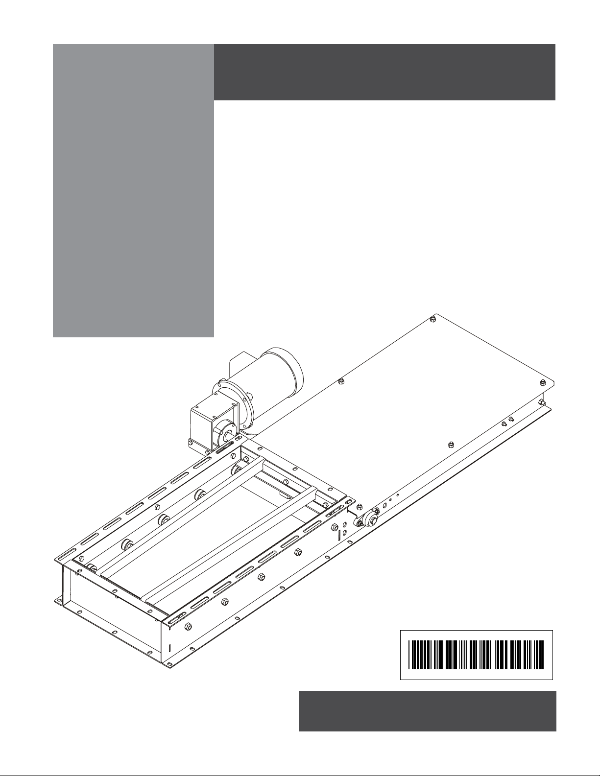
In-line Intermediate
Discharge Gates
Installation Manual
PNEG-765
Date: 9-2-05
PNEG-765
Page 2
SAFETY
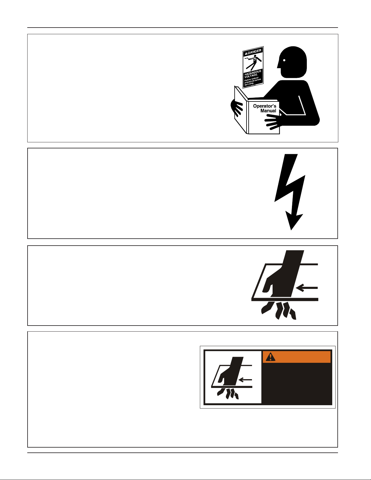
FOLLOW SAFETY INSTRUCTIONS
Learn how to operate the machine and how to use controls properly . Do not let anyone operate without instruction.
Keep your machinery in proper working condition. Unauthorized modifications to the machine may impair the
function and/or safety and affect machine life.
If you do not understand any part of this manual and need
assistance, contact your dealer.
INSTALL & OPERATE ELECTRICAL
EQUIPMENT PROPERLY
Electrical controls should be installed by a qualified
electrician and must meet the standards set by the
national electrical code and all local and state
codes.
Electric Shock
Hazard
Disconnect and lock out all power sources before
installing wires/cables or servicing equipment .
STAY CLEAR OF MOVING PARTS
Keep arms and hands away from slide gate opening.
Slide Gate can crush and dismember. Motor may
start at any time.
Always stop and lock out power source before making adjustments, cleaning, or maintaining equipment.
DECALS
Please remember, safety decals provide important
safety information for people working near equipment that is in operation. If a safety sign cannot be
easily read for any reason or has been painted
over , replace it immediately . Additional Safety signs
may be obtained from your dealer, distributor , or
ordered from the factory free of charge.
Crush
Hazard
WARNING
Moving side plate.
Auto equipment can
start at any time.
Disconnect and lockout
before servicing.
DC-1248
CONT ACT : The GSI Group
1004 E. Illinois St.
Decal #: DC-1248
(Not to scale.)
Assumption, IL 62510
217-226-4421
2 PNEG-765 Gate Manual
Page 3
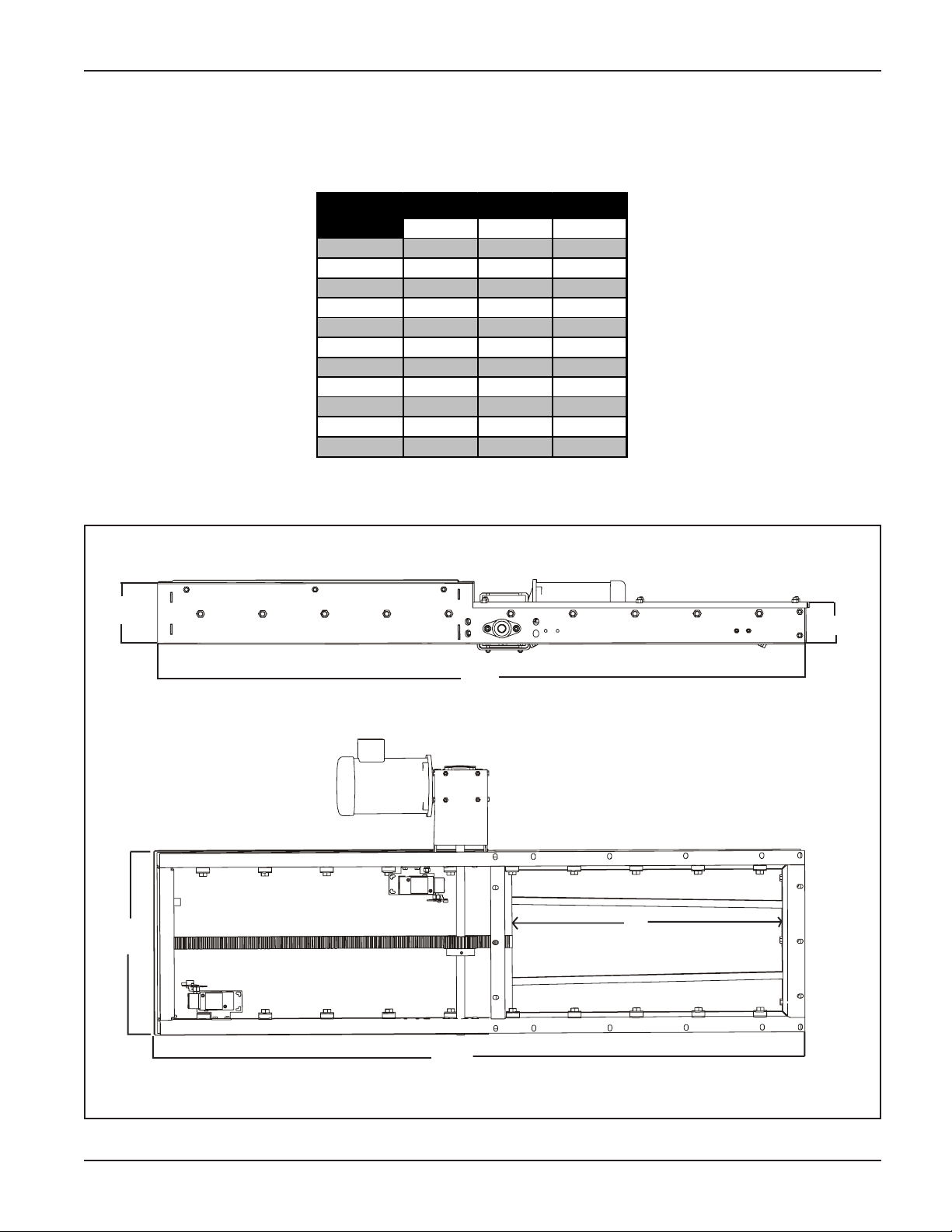
OVERALL GATE DIMENSIONS
Overall Gate Dimensions
Conv. Size
0912
1212
1612
1214
1614
2114
1420
1620
2020
2620
3220
ABC
9.00 30.00
12.00 30.00
16.00 30.00
12.00 30.00
16.00 30.00
21.00 30.00
14.00 36.00
16.00 36.00
20.00 36.00
26.00 36.00
32.00 36.00 81.125
68.125
68.125
68.125
68.125
68.125
68.125
81.125
81.125
81.125
81.125
6.50"
A
4.31"
C
B
C
Overall Gate Dimensions
3PNEG-765 Gate Manual
Page 4

Cut Out Discharge Hole in Trough Bottom
1. T o find where to cut hole in trough bottom, start by locating the center of the purposed discharge.
Dimension “A”. (Refer to Figure 1.)
2. When locating discharges try to position opening so that gate flange hole pattern and conveyor
hole pattern lineup. The gate has slotted holes to allow for adjustment to nearest 1".
3. If this cannot be achieved then holes must be drilled on site.
4. Find dimensions “B” and “C” corresponding to your conveyor size. Use “D” dimensions as a
reference. (See Figure 1 and chart below.)
5. Mark the cut out from outside the conveyor on the trough bottom.
6. Cut opening into the bottom being careful not to damage other components of the Conveyor .
Remove all burrs and rough edges from the opening.
Trough Hole Dim ensi ons
Conv. S i ze
0912
1212
1612
1214
1614
2114
1420
1620
2020
2620
3220
2626
3226
3232
3632
BCD
9.00 30.125
12.00 30.125
16.00 30.125
12.00 30.125
16.00 30.125
21.00 30.125
14.00 36.125
16.00 36.125
20.00 36.125
26.00 36.125
32.00 36.125
26.00 36.125 2.00
32.00 36.125 2.00
32.00 36.125 2.00
36.00 36.125 2.00
1.50
1.50
1.50
1.50
1.50
1.50
2.00
2.00
2.00
2.00
2.00
D
Conveyor
Bottom
C
B
Figure 1
A
4 PNEG-765 Gate Manual
Page 5

Manual Gate Installation
Manually Operated Gate
1. Install the specified wheel to the shaft by aligning the key and key way , then tighten the set
screw. This gate can be operated by a chain, cable, or hand wheel.
2. Manual gates up to 16" wide are fitted with a single rack. Manual gates larger than 16" wide
have a double rack.
3. The slide gate plate rides on 1-3/8" double shielded radial bearings for smooth operation.
Hand Wheel
Key
Shaft
Figure 2
Gate Frame
5PNEG-765 Gate Manual
Page 6

Motor Driven Gate Installation
Install Motor Bracket
1. Install the motor bracket to the gate. Then
attach the motor to the bracket as shown
in Figure 3, using the provided hardware.
Install Limit Switch
1. Using limit switches that are available in
Nema 4 or explosion proof standards,
achieves accurate positioning of these
gates. Limit Switches are located on both
sides of the frame to detect when the gate
is totally open or closed.
2. Attach the switch brackets to the inside of
the gate as shown using hardware
provided. (See Figure 4.) Att ach limit
switch to the bracket as shown. (See
Figure 5.)
3. After switches are securely fastened.
Adjust lever arms so they come in contact
with tripper blocks on underneath side of
slide plate.
4. Disconnect the power at the electrical
panel, run the proper gauge electrical wire
to the motors and limit switches. (See
Wiring Diagram on page 9.) Be sure that
the limit switches are adjusted
properly before operating the gate!
Turn the power back on and CAUTIOUSL Y
operate the gate, opening and closing the
gate slide, making the necessary
adjustments to the limit switch arms to
assure complete opening and closing of
the gate.
5. Motor driven gates are available in both
TEFC and explosion proof configurations.
Motor
Bracket
Limit
Switch
Switch
Bracket
Motor
Shaft
Key
Keyway
Figure 3
Figure 4
Switch
Bracket
Figure 5
6 PNEG-765 Gate Manual
Page 7

Side View with side
removed for clarity .
Figure 6
Tripper Block
Actuator Arm
Limit Switch
Cover
Slide Gate
Tripper Block
EXPLODED VIEW shown
without side for clarity .
Slide Gate
GATE CLOSED POSITION
shown without side for clarity .
GATE OPENED POSITION
shown without side for clarity .
Actuator
Arm
Limit
Switch
Tripper Block
Actuator Arm
Slide Gate
Actuator Arm
Figure 7
Figure 8
Tripper Block
Figure 9
7PNEG-765 Gate Manual
Page 8

Install Gate Frame to Trough
1. Assemble the gate frame to the bottom of the trough section using the existing hardware in
the trough bottom.
2. Adjust the carry over bars flush to the bottom of your conveyor . (Note: Failure to adjust carry
over bars properly will cause severe damage to chain and/or gate.
3. It is preferred that the gate is oriented so it closes towards the head section.
Trough Section
Gate Assembly
Carry Over Bars
Figure 10
8 PNEG-765 Gate Manual
Page 9

Typical Wiring Diagram
OPEN
CLOSE
STOP
1
1
O
N.C.
C
N.C.
2
2
4
6
3
7
5
2
1
G
N
I
S
R
E
V
E
R
R
E
T
R
A
T
S
L1
L2
L3
T1
T2
T3
M
Remove internal jumpers 3 to 6, 5 to 7.
O
C
Open position switch.
Closed position switch.
Break for momentary operation.
9PNEG-765 Gate Manual
Page 10

Copyright © 2005 by The GSI Group
Printed in the USA
The GSI Group
1004 E. Illinois St.
Assumption, IL 62510
217-226-4421
 Loading...