

Page 1

PNEG-751-G2
12" Series II Sweep
131' and 135' Diameter
Owner ’s Manual
PNEG-751-G2
Version: 1.0
Date: 11-22-11
Page 2

Model Number of My Sweep:
__________________________________
Date Delivered:
__________________________________
Date Installed:
__________________________________
NOTE: The manufacturer reserves the right to improve its product whenever possible and practical to
do so. We reserve the right to change, improve and modify products at any time without
obligation to make changes, improvements and modifications on equipment sold previously.
Personnel operating or working around this equipment should read this manual. This manual
must be delivered with equipment to its owner. Failure to read this manual and its safety
instructions is a misuse of the equipment. Any misuse of the equipment may void the warranty.
2 PNEG-751-G2 12" Series II Sweep 131' and 135' Diameter
Page 3

Table of Contents
Contents
Chapter 1 Introduction ..........................................................................................................................................5
Product Introduction .............................................................................................................................. 5
Chapter 2 Safety .....................................................................................................................................................7
Safety Guidelines .................................................................................................................................. 7
Safety Instructions ..................... ... .... .......................................... ... ... ..................................................... 8
Operator Qualifications ....................................................................................... .... ... ... ... ................... 12
Chapter 3 Safety Decals ......................................................................................................................................13
Chapter 4 General Product Information ............................... ....................... ...................... .................................17
Product Information ............................................................................................................................. 17
General Information ............................................................................................................................ 17
Capacities and Specifications ............................................................................................................. 18
Q-D Bushings - Reverse Mounting ..................................................................................................... 21
Chapter 5 Assembly ............................................................................................................................................23
Back Shield Assembly ......................... ... ... ... .... ... ... ... .... ... .......................................... ... ... ... ................ 23
Flighting Assembly .............................................................................................................................. 24
Hanger Bracket Assembly ...................... ... ... .... ... .......................................... ... ... .... ... ... ... ................... 25
Flange Bearing Assembly ...................... ... ... .... ... ... ... .... ... .......................................... ... ... ... ................ 26
Gear Reducer Assembly ............................................... ... ... .......................................... ... ... ................ 26
Drive Axle Assembly and Bearing Support ......................................................................................... 27
Install Reducer Mounting Plate and Reducer ...................................................................................... 29
Key Alignment ..................................................................................................................................... 30
Install Tractor Drive Motor ................................................................................................................... 31
Guard Assembly .................................................................................................................................. 32
Tractor Wheel Assembly ..................................................................................................................... 34
Weight Placement ............................................... ... ... .......................................... .... ... ... ...................... 35
Channel Extension Kit ............................... ... .... ... ... ... .... ... ... ... .... ... ... ................................................... 36
Motor Jack and Base Assembly .......................................................................................................... 37
Motor Installation ................................................................................................................................. 38
Sheave Installation .............................................................................................................................. 39
Electrical Assembly ............................................................................................................................. 42
Jack Support Assembly ....................................................................................................................... 46
Center Pivot Installation ...................................................................................................................... 48
Control Panel Setup ............................................................................................................................ 51
Calibration ........................................................................................................................................... 56
Operation ............................................................................................................................................ 57
Chapter 6 Start-Up ...............................................................................................................................................58
Perform Pre-Start Checks ......................................... .... .......................................... ... ... ... ................... 58
Start the Auger .................................................................................................................................... 59
Chapter 7 Operation ............................................................................................................................................60
Operating the Sweep Auger ............................................................................. ... .... ... ... ... ... .... . ........... 60
Operating the Sweep Auger Control Panel ......................................................................................... 61
Chapter 8 Shut Down ...........................................................................................................................................62
Normal Shut Down .............................................................................................................................. 62
Emergency Shut Down .................................................... ... ... .... ... ... ... ... .... ... ... ................................... 62
Storage Preparation .................................................. .... .......................................... ... ... ... ..
Chapter 9 Maintenance ........................................................................................................................................63
Maintain the Auger .............................................................................................................................. 63
Lubrication .............................. ............. ............. ............. ............. ............ ............. ................................ 64
PNEG-751-G2 12" Series II Sweep 131' and 135' Diameter 3
................. 62
Page 4

Table of Contents
Chapter 10 Control Panel Diagrams ...................................................................................................................69
Control Panel Schematic (460/3/60) Pre-June 2010 ......................................................................... 69
Grain Sweep Schematic Post-June 2010 (S2PFA) ........................................................................... 70
Grain Sweep Schematic Post-June 2010 (S2PFB) ........................................................................... 71
Grain Sweep Schematic Post-June 2010 (S2PFC) ........................................................................... 72
Chapter 11 Troubleshooting ...............................................................................................................................73
FAQs ................................................................................................................................................. 74
Chapter 12 Parts List ...........................................................................................................................................81
Main Auger Components .................... ... ... ... .......................................... .... ... ... ... .... ... ... ... ... ............... 82
Flight Components ............................................................................................................................ 84
End Bearing Components ................................................................................................................. 85
Auger Drive Components .................................................................................................................. 86
Drive Assembly .................................................................................................................................. 88
Tractor Chain Guard Parts ................................................................................................................ 90
Motor Mount Jack and Base Assembly (GC09993) .......................................................................... 91
Jack Supports .................................................................................................................................... 92
Control Panel Components (S2PFA) ........... .... ... ... ... .... ... ... ... .... ... ... ... ... .... ........................................ 94
Control Panel Components Post-June 2010 (S2PFA) ................................. ... ... .... ... ... ... ... .... ... ... ... .. 96
Control Panel Components Post-June 2010 (S2PFB) ................................. ... ... .... ... ... ... ... .... ... ... ... .. 98
Control Panel Components Post-June 2010 (S2PFC) ................................................................. ... 100
Weight Extension Kit (GC12311) . .... ... ... ... .......................................... ... .... ... ... ... .... ......................... 102
Chapter 13 Warranty ..........................................................................................................................................103
4 PNEG-751-G2 12" Series II Sweep 131' and 135' Diameter
Page 5

1. Introduction
Product Introduction
Congratulations. Your selection of the GSI Series II Sweep is a wise investment. It will give you years of
dependable service. The main function of the Series II Sweep is to clean out the remaining grain, from the
bin, after all gravity unloading has finished. The GSI Series II Sweep is a single pass sweep only. The unit
will only operate in a round grain bin equipped with a center sump in the bin floor. NOTE: The bin
manufacturer should be contacted for their recommendations on your bin’s structural integrity. The
following are sweep criteria recommendations.
Issues Recommendations
A track is required under each of the sweep tires and jack wheels where they travel
over the aeration (steel) floor. This is the case for all steel flooring including full floor
and flush floor aeration. The track should be a minimum of 10 gauge thick and made
from steel. The steel can be galvanized for the jack wheel paths but needs to have a
non-slip coating for the drive tire paths. The drive tire track coating must not be course
Flooring.
enough to damage the drive tires. A Chart on Page 17 is included that shows radius
dimensions locating the points of contact between the sweep and the bin floor. The
dimensions may be used to figure the material quantities of track to support the sweep
across the aeration flooring. The track material is not supplied with the sweep and
must be supplied by the installer or purchased from GSI. The dimensions are
approximate and the assembled sweep should be checked for exact points of contact.
Center sump size.
Number of intermediate sumps.
Routing the power supply to
the sweep.
Floor level tolerance.
If installing a sump with collector ring, the opening will be 42" x 42" for 12" sweep size.
The sump hopper supplied by GSI was designed with sufficient clearance around
the collector ring housing to allow grain to gravity flow through the hopper and be
carried away by the material handling equipment below. 42-3/4" is the maximum
opening size to allow rolling clearance for the casters assembled to the head end jack.
If made smaller, grain flow may be decreased to an unacceptable level.
**Flow of grain is limited to 15000 BPH when using this sump and collector ring
housing assembly. The collector ring housing extends 22-1/2" down from the floor
surface and is approximately 14-1/4" x 14-1/4" in size.
Intermediate sump pumps must be installed on a maximum of 10' centers where the
sweep will be parked during storage. The first intermediate sump should be placed at
a maximum of 10' from the center sumps and the end sump should be no more than
4' from the bin wall.
The extra sumps will help clean out the grain in front of the sweep, reducing the
start-up load. Doing this will save labor dollars and hours of work to dig out the sweep
and will help the sweep during start-up. The sweep is not designed to start-up when
submerged in material. The sweep should be parked behind the intermediate sumps
with sumps on the auger side of the sweep.
The only option is to use the hopper sump with collector ring. This allows the power
to be transferred through a mechanical device in the center sump and does not twist
any cords.
The top edge of the sump hopper and the top edge of the “X” brace support must be
level with the floor. The floor must be level within 3/4" plus (or) minus, preferably less.
Any high or low points must be gradually sloped. The change in elevation should be
no more than 3/4" over 60".
Diameter tolerances are limited by foundation limits and sweep operation as well as
Bin roundness tolerance.
structural issues. For 72' diameter and larger, the overall tolerance would be plus or
minus 1-1/4" on the radius, plus or minus 1" on 42'-66' diameter bins and plus or
minus 3/4" on 30'-39' bins.
PNEG-751-G2 12" Series II Sweep 131' and 135' Diameter 5
Page 6

1. Introduction
Issues Recommendations
Bin opening size required
for installation.
Vo ltage specification.
Electrical requirements.
The tail section is the largest piece of a standard Series II Sweep. The dimensions for a
12" tail section are 21-1/4" x 51-1/2". If the bin wall is not too thick, this unit should fit
through a 21-1/2" x 45" opening.
The Series II Sweep is designed to operate using 460 volt 3 phase 60 cycle power.
The voltage must be within plus or minus 4% for proper operation. Volt ages outside
of this range may cause excessive power draw or other operating problems. Please
contact the factory for applications outside of these parameters.
Electrical controls and wiring should be installed by a qualified electrician. The
conductor cables should comply with the National Electric Code and any local codes
which may apply.
Disconnect and lock out the power before servicing the equipment, entering the bin
or resetting the motor overloads.
The control panel MUST be mounted OUTSIDE the bin near the door. It must be
located so the operator has a full view of the equipment and can see that all personnel
are clear. It must NEVER be installed inside the bin. The foot switch has to be plugged
into the control panel and depressed before the sweep is operational. It has a 10' cord
so the sweep can only be monitored from OUTSIDE the bin. The thermal protection
cord must also be plugged in before the sweep will operate.
6 PNEG-751-G2 12" Series II Sweep 131' and 135' Diameter
Page 7
2. Safety
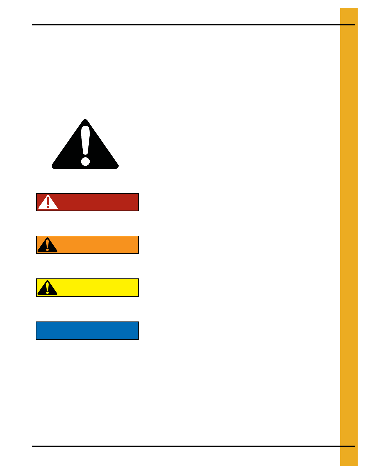
DANGER
WARNING
CAUTION
NOTICE
This is the safety alert symbol. It is used to alert you
to potential personal injury hazards. Obey all safety
messages that follow this symbol to avoid possible
injury or death.
WARNING indicates a hazardous situation which, if not
avoided, could result in death or serious injury.
CAUTION, used with the safety alert symbol, indicates a
hazardous situation which, if not avoided, could result in
minor or moderate injury.
NOTICE is used to address practices not related to
personal injury.
DANGER indicates a hazardous situation which, if not
avoided, will result in death or serious injury.
Safety Guidelines
This manual contains information that is important for you, the owner/operator, to know and understand.
This information relates to protecting personal safety and preventing equipment problems. It is the
responsibility of the owner/operator to inform anyone operating or working in the area of this equipment
of these safety guidelines. To help you recognize this information, we use the symbols that are defined
below. Please read the manual and pay attention to these sections. Failure to read this manual and its
safety instructions is a misuse of the equipment and may lead to serious injury or death.
PNEG-751-G2 12" Series II Sweep 131' and 135' Diameter 7
Page 8
2. Safety
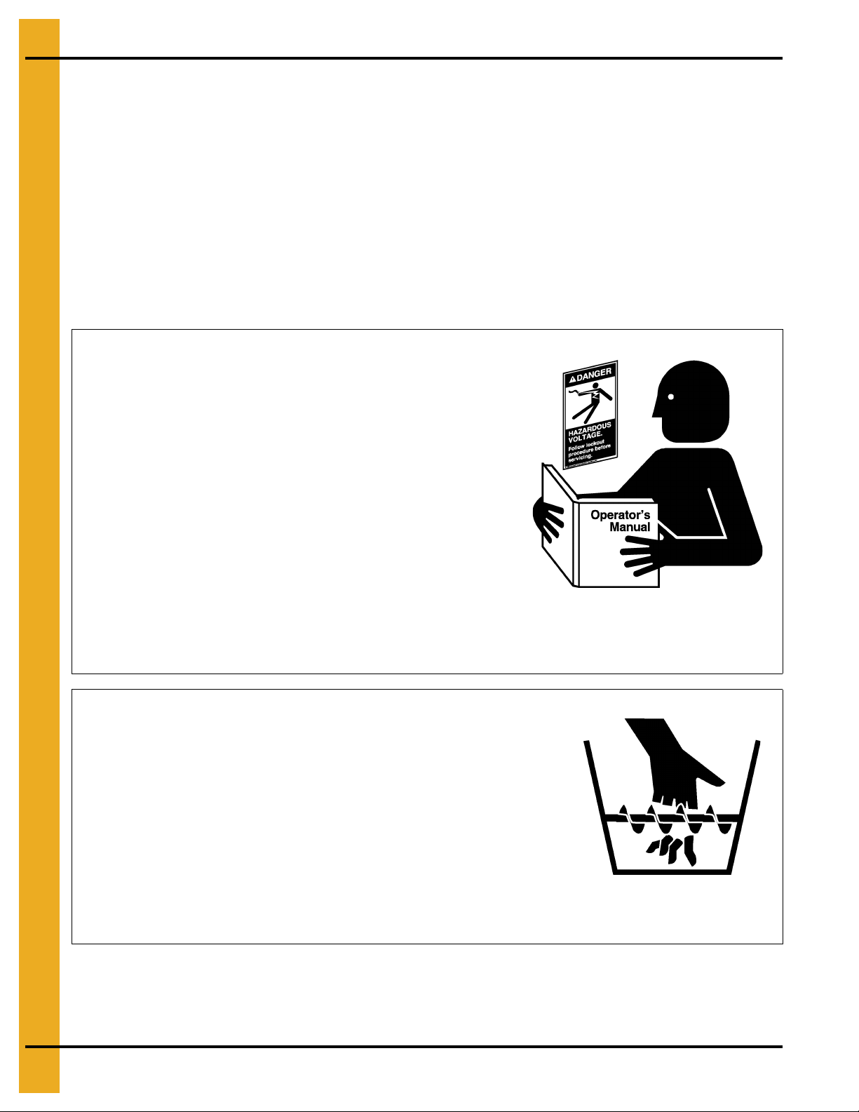
Read and Understand Manual
Follow Safety Instructions
Carefully read all safety messages in this manual and
safety signs on your machine. Keep signs in good
condition. Replace missing or damaged safety signs. Be
sure new equipment components and repair parts include
the current safety signs. Replacement safety signs are
available from the manufacturer.
Learn how to operate the machine and how to use controls
properly. Do not let anyone operate without instruction.
Keep your machinery in proper working condition.
Unauthorized modifications to the machine may impair
the function and/or safety and affect machine life.
If you do not understand any part of this manual or need
assistance, contact your dealer.
Keep Hands Away from Moving Parts
DO NOT put hand or arm in hopper. Rotating auger can
crush and dismember.
DO NOT put any kind of tool inside hopper to try and clear
debris while the auger is running. Damage to the equipment
will result.
ALWAYS turn off and lock out all power sources before
servicing equipment.
Keep all shields and covers in place during operation.
Rotating Auger
Safety Instructions
Our foremost concern is your safety and the safety of others associated with this equipment. We want to
keep you as a customer. This manual is to help you understand safe operating procedures and some
problems that may be encountered by the operator and other personnel.
As owner and/or operator, it is your responsibility to know what requirements, hazards, and precautions
exist, and to inform all personnel associated with the equipment or in the area. Safety precautions may be
required from the personnel. Avoid any alterations to the equipment. Such alterations may p roduce a very
dangerous situation where SERIOUS INJURY or DEATH may occur.
This equipment shall be installed in accordance with the current installation codes and applicable
regulations, which should be carefully followed in all cases. Authorities having jurisdiction should be
consulted before installations are made.
8 PNEG-751-G2 12" Series II Sweep 131' and 135' Diameter
Page 9

2. Safety
Operate Motor Properly
In an emergency, shut down the power source.
Turn OFF and lock out all power sources before performing
any maintenance.
Do not operate electric motor equipped units until motors are
properly grounded.
Disconnect power on electrical driven units before resetting
motor overloads.
Do not repetitively stop and start the drive in order to free a
plugged condition. Jogging the drive in this manner can damage
the equipment and/or drive components.
Electric Shock Hazard
Maintain Equipment
and Work Area
Practice Safe Maintenance
Understand service procedures before doing work. Keep area
clean and dry.
Never lubricate, service, or adjust machine while it is in operation.
Keep hands, feet, and clothing away from rotating parts.
Keep all parts in good condition and properly installed. Fix
damage immediately . Replace worn or broke n parts. Remove an y
built-up grease, oil, and debris.
Keep Emergency Equipment
Quickly Accessible
Prepare for Emergencies
Be prepared if fire starts.
Keep a first aid kit and fire extinguisher handy.
Keep emergency numbers for doctors, ambulance service,
hospital, and fire department near your telephone.
PNEG-751-G2 12" Series II Sweep 131' and 135' Diameter 9
Page 10
2. Safety
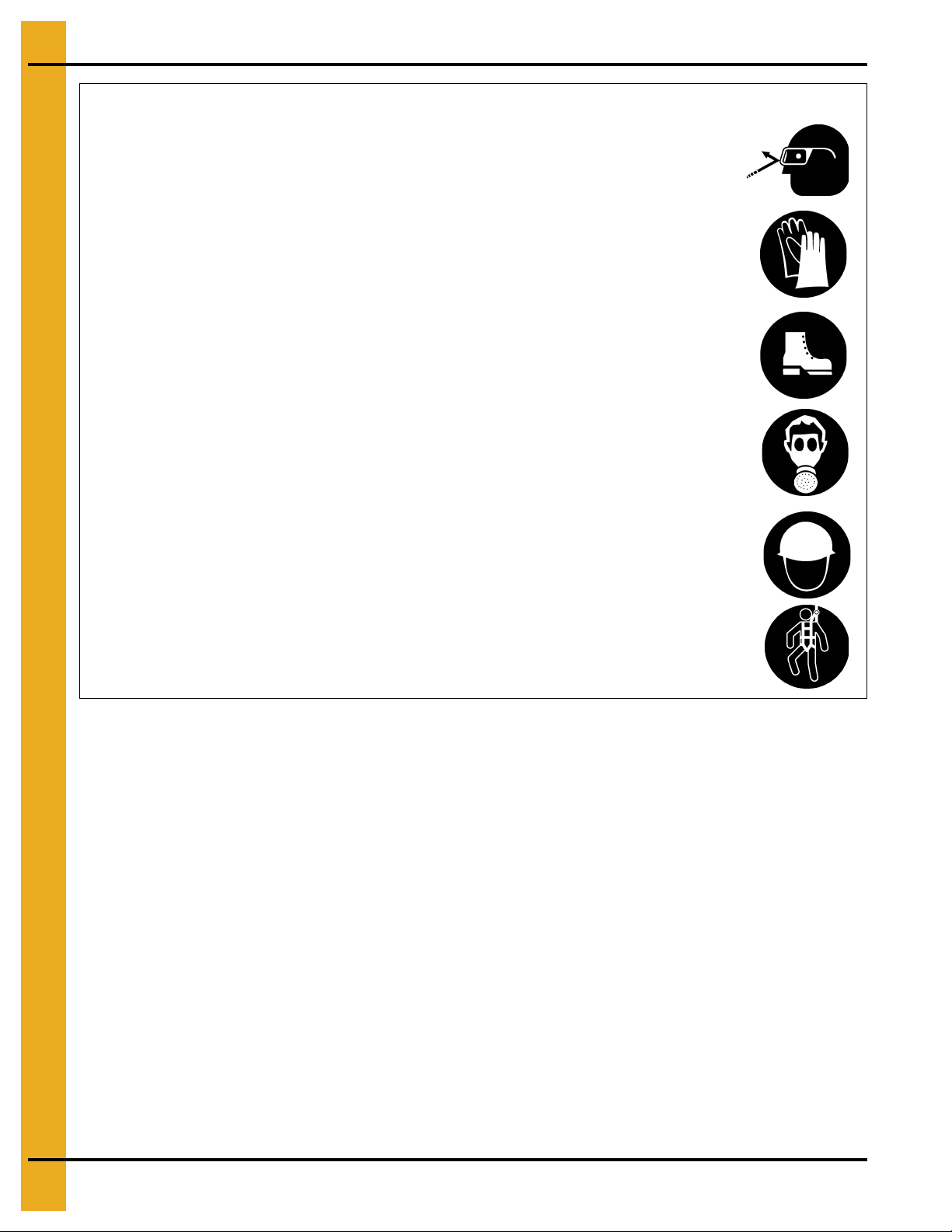
Eye Protection
Gloves
Steel Toe Boots
Respirator
Hard Hat
Fall Protection
Wear Protective Clothing
Wear close-fitting clothing and safety equipment appropriate
to the job.
Remove all jewelry.
Tie long hair up and back.
Wear safety glasses at all times to protect eyes from debris.
Wear gloves to protect your hands from sharp edges on
plastic or steel parts.
Wear steel-toed boots to help protect your feet from falling
debris. Tuck in any loose or dangling shoestrings.
A respirator may be needed to prevent breathing potentially
toxic fumes and dust.
Wear a hard hat to help protect your head.
Wear appropriate fall protection equipment when working at
elevations greater than six feet (6').
10 PNEG-751-G2 12" Series II Sweep 131' and 135' Diameter
Page 11

Operate Unload Equipment Properly
• Untrained operators subject themselves and others to SERIOUS INJURY
or DEATH. NEVER allow untrained personnel to operate this equipment.
• NEVER work alone.
• Keep children and other unqualified personnel out of the working
area at ALL times. Refer to the Start-Up section of this manual for
diagrams of the work area.
• Make sure ALL equipment is locked in position before operating.
• NEVER start equipment until ALL persons are clear of the work area.
• Keep hands and feet away from the auger intake and other moving parts.
• NEVER attempt to assist machinery operation or to remove trash from equipment while
in operation.
• Be sure all operators are adequately rested and prepared to perform all functions of operating
this equipment.
• NEVER allow any person intoxicated or under the influence of alcohol or drugs to operate
the equipment.
• Make sure someone is nearby who is aware of the proper shut down sequence in the event of an
accident or emergency.
• ALWAYS think before acting. NEVER act impulsively around the equipment.
• NEVER allow anyone inside a bin, truck or wagon which is being unloaded by an auger or
conveyor. Flowing grain can trap and suffocate in seconds.
• Use ample overhead lighting after sunset to light the work area.
• Keep area around intake free of obstacles such as electrical cords, blocks, etc., that might
trip workers.
• NEVER drive, stand or walk under the equipment.
• Use caution not to hit the auger when positioning the load.
• ALWAYS lock out ALL power to the equipment when finished unloading a bin.
• Be aware of pinch points. A pinch point is a narrow area between two surfaces t hat is likely to trap or
catch objects and so is a potential safety hazard.
Operate Unload
Equipment Safely
2. Safety
PNEG-751-G2 12" Series II Sweep 131' and 135' Diameter 11
Page 12

2. Safety
Operator Qualifications
A. The User/Operator must be competent and experienced to operate auger equipment. Anyone who
works with or around augers must have good common sense in order to be qu alified. These persons
must also know and meet all other qualifications, such as:
i. Any person who has not read and/or does not understand all operation and safety procedures
is not qualified to operate any auger systems.
ii. Certain regulations apply to personnel operating power machinery. Personnel under the age of
18 years may not operate power machinery, including augers. It is your responsibility, as owner
and/or supervisor, to know what these regulations are in your area or situation.
iii. Unqualified or incompetent persons are to remain out of the work area.
iv. O.S.H.A. (Occupational Safety and Health Administration) regulations state: “At the time of
initial assignment and at least annually thereafter, the employer shall instruct every employee
in the safe operation and servicing of all equipment with which the employee is, or will be
involved”. (Federal Occupational Safety and Health Standards for Agriculture. Subpart D,
Section 1928.57 (a) (6)).
B. As a requirement of O.S.H.A., it is necessary for the employer to train the employee in the safe
operating and safety procedures for this auger. The sign-off sheet is provided for your convenience
and personal record keeping. All unqualified persons are to stay out of the work area at all times. It
is strongly recommended that another qualified person who knows the shut down procedure is in the
area in the event of an emergency.
Date Employee Name Supervisor Name
12 PNEG-751-G2 12" Series II Sweep 131' and 135' Diameter
Page 13
3. Safety Decals
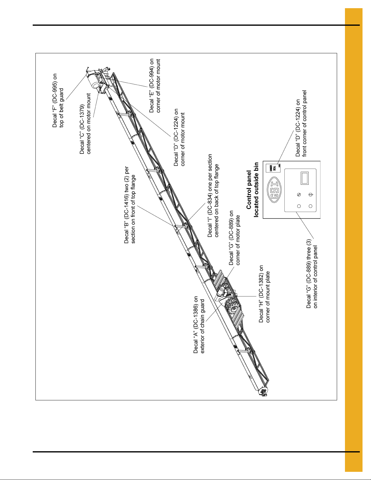
The images below show the location of the decals and safety signs which should appear on the
Series II Sweep. (Refer to Pages 14-16 for decals.)
NOTE: Please remember safety signs provide important safety information for people working near bin
unloading equipment that is in operation.
Any safety signs that are worn, missing, illegible or painted over should be replaced immediately.
Obtain FREE replacements by contacting GSI.
PNEG-751-G2 12" Series II Sweep 131' and 135' Diameter 13
Page 14
3. Safety Decals
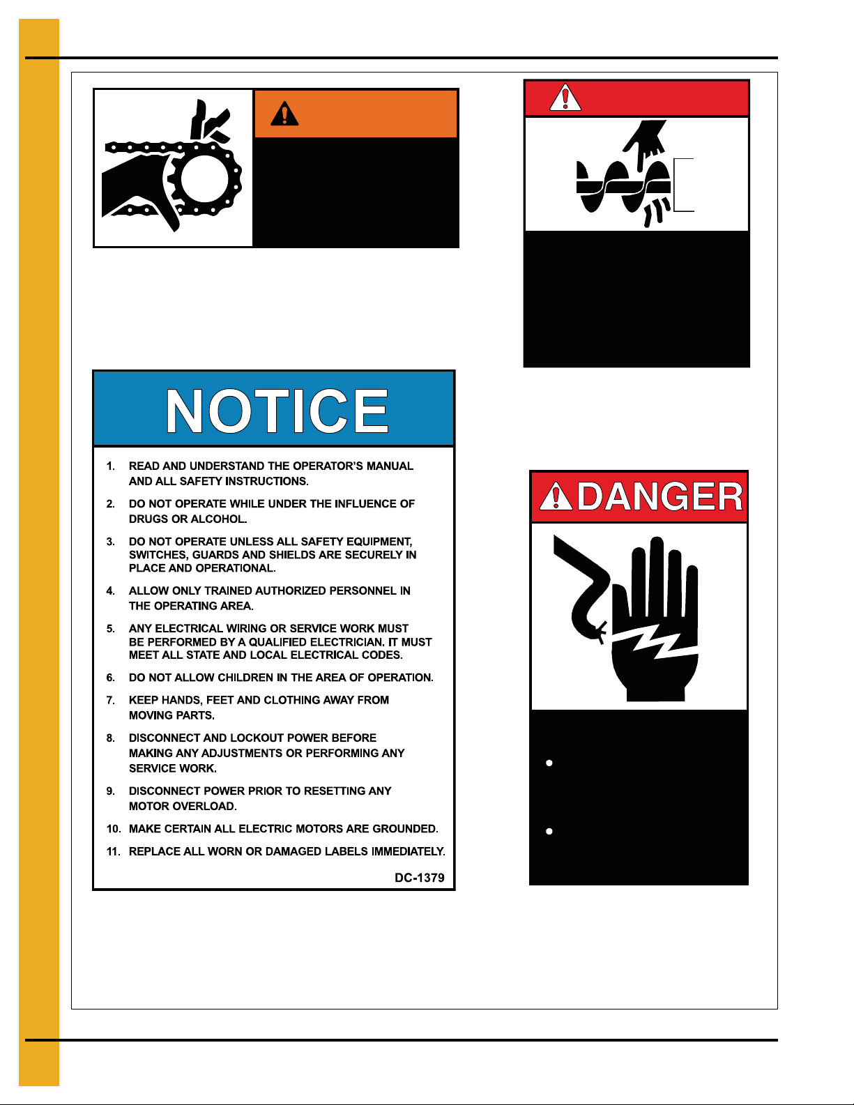
SHEAR POINT
Moving parts can
crush and cut. Keep
hands clear of
sprocket and chain.
DC-1386
WARNING
ROTATING AUGER!
• DISCONNECT AND LOCKOUT P OWER BEFORE
SERVICING, ADJUSTING OR CLEANING.
• KEEP HANDS, FEET, HAIR AND LOOSE
CLOTHING AWAY FROM ROTATING AUGER AND
MOVING PARTS AT ALL TIMES.
• NEVER REMOVE O R MODIFY GUARDS OR
SHIELDS.
FAILURE TO HEED WILL RESULT IN
SERIOUS INJURY OR DEATH!
DC-1416
DANGERDANGER
Decal “A”
Location: Exterior of chain guard
Size: 2" x 4-1/2"
Part #: DC-1386
Decal “B”
Location: Two (2) per section on
front of top flange
Size: 4-5/16" x 5-7/16"
Part #: DC-1416
Decal “C”
Location: Centered on motor mount
Size: 5-1/2" x 7-3/8"
Part #: DC-1379
Decal “D”
Location: Corner of motor mount
Size: 2-7/8" x 5"
Part #: DC-1224
HIGH VOLTAGE.
Will cause serious
injury or death.
Lockout power
before servicing.
DC-1224
14 PNEG-751-G2 12" Series II Sweep 131' and 135' Diameter
Page 15

SHEAR POINT
SHEAR POINT
Keep hands clear of moving
parts. Do not operate with
guard removed. Disconnect
and lockout power before
servicing.
DC-995
WARNING
Decal “G”
Location: Corner of motor mount
Size: 2-13/16" x 17/16"
Part #: DC-889
Decal “F”
Location: Top of belt guard
Size: 4-1/2" x 2"
Part #: DC-995
Decal “E”
Location: Corner of motor mount
Size: 4-1/2" x 2"
Part #: DC-994
Decal “H”
Location: Corner of mount plate
Size: 4" x 1-3/4"
Part #: DC-1382
Decal “I”
Location: One per section centered on back of top flange
Size: 9" x 3-3/4"
Part #: DC-834
Keep hands clear of moving
parts. Do not operate with
guard removed. Disconnect
and lockout power before
servicing.
3. Safety Decals
DC-994
SHEAR POINT
Moving parts can
crush and cut. Keep
hands clear of
sprocket and chain.
DC-1382
PNEG-751-G2 12" Series II Sweep 131' and 135' Diameter 15
Page 16
3. Safety Decals
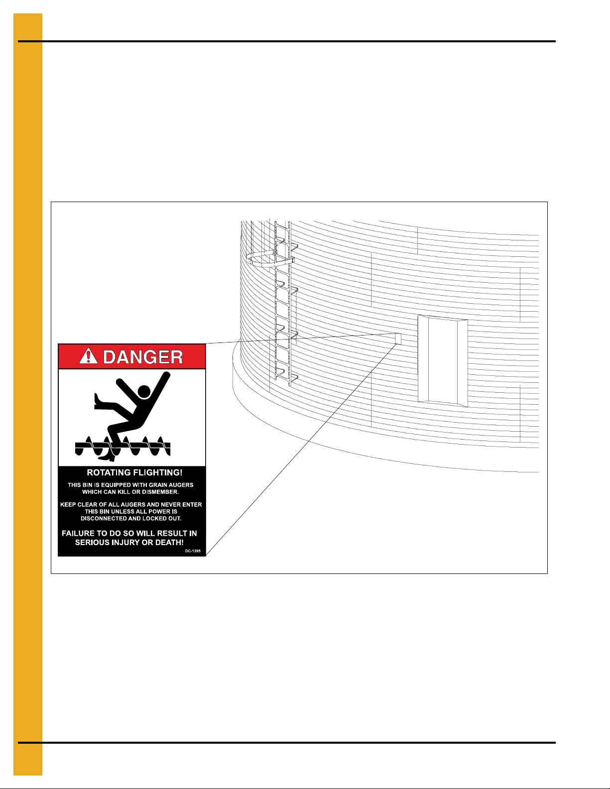
A. DANGER Sign No. DC-1395 was supplied with your bin unloading equipment. This safety sign
should be applied to the side of the bin near the bin opening, so it will be viewed by people entering
into the bin storage building. Do not cover any safety signs or any other signs that are already there.
B. If the safety sign location suggested is not in full view because of equipment modifications, other
equipment in the area or any reason, then locate the safety sign in a more suitable location.
C. Be certain the surface is clean, dry and free of dirt and oil. Peel paper backing from decals and stick
into place. The adhesive backing will bond on contact.
NOTE: Please remember, safety signs provide important safety information for people working near bin
unloading equipment that is in operation.
NOTE: If the Safety Sign cannot be easily read for any reason or has been painted over, replace it
immediately. Additional Safety Signs may be obtained free of charge from your dealer, distributor
or ordered from the factory.
Order SAFETY SIGN NO. DC-1395
16 PNEG-751-G2 12" Series II Sweep 131' and 135' Diameter
Page 17
4. General Product Information
This Series II Sweep is a single pass sweep. Consult the manufacturer of the
storage tank regarding the requirements or restrictions of the sweeping process.
The manufacturer may require a multiple pass sweep.
WARNING
NEVER enter a grain bin unless ALL power driven equipment has been shut down.
Disconnect and lock out power before entering the bin or servicing the equipment.
Product Information
CAUTION
A. The Series II Sweep includes the following components.
• Control panel
• Two (2) motors
•Motor covers
• Motor mount
• Auger flighting
• Auger back shield assembly
• Jack supports
B. The unit will operate only in a round grain bin equipped with a center sump in the bin floor.
General Information
A. GSI reserves the right to improve its product whenever possible and practical to do so. We reserve
the right to change, improve and modify products at any time without obligation to make changes,
improvements and modifications on equipment sold previously.
B. This new bin sweep auger has been engineered and manufactured to give years of dependable
service. The care and maintenance of this equipment will affect the satisfaction and service
obtained. By following the instructions and recommendations, the owner should receive quality
service for many years. If additional information or assistance is required, please contact GSI.
C. It is important to check both the quantity of parts and their descriptions with the packing list enclosed
within each package. All claims for freight damage or shortage must be made by the consignee
within ten (10) days of the date of the occurrence. The consignee should accept the shipment after
noting the damage or loss on the bill of lading.
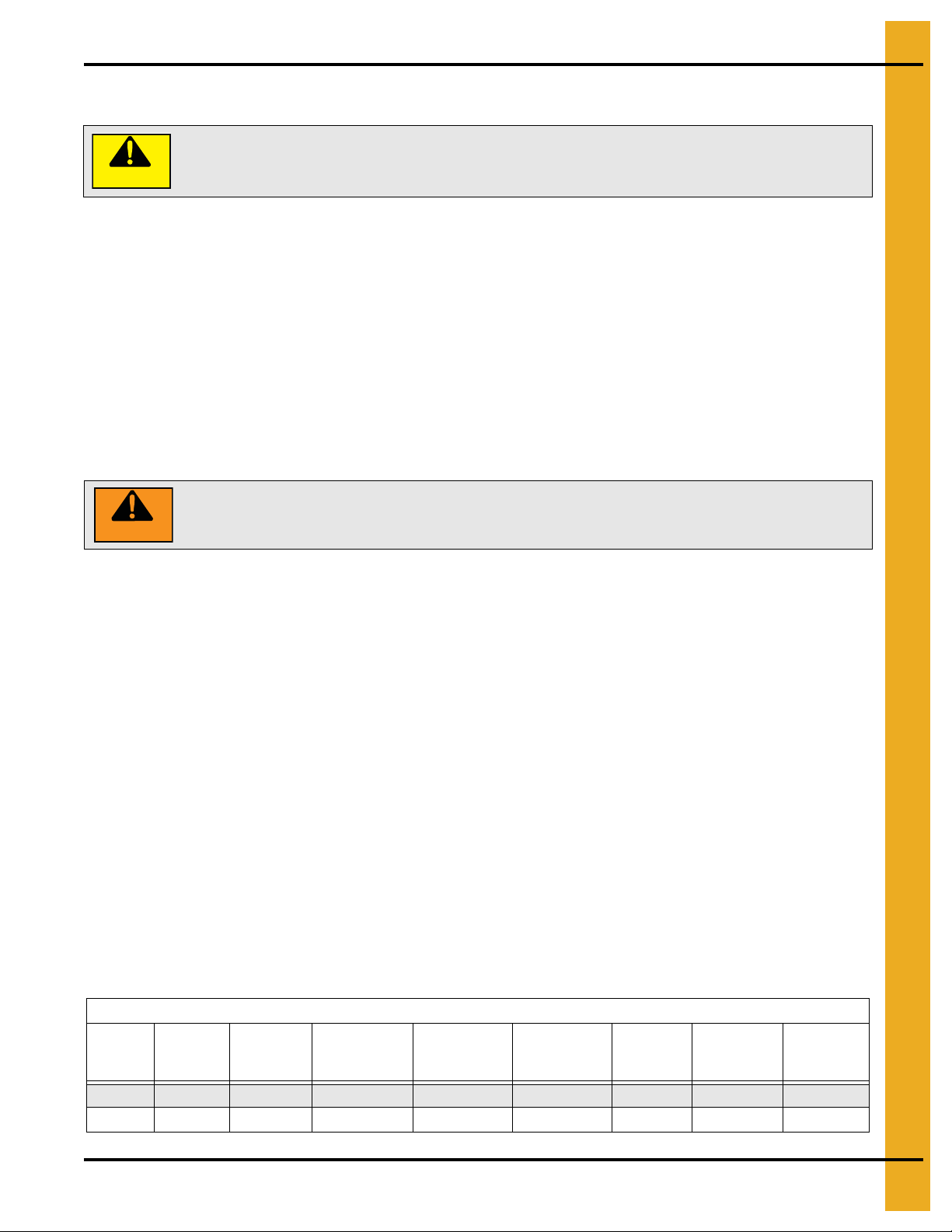
D. The Chart below shows radius dimensions locating the points of contact between the sweep and the
bin floor. The dimensions may be used to figure material quantities of track to support the sweep
across the aeration flooring. The track material is not supplied with the sweep and must be supplied
by the installer. The dimensions are approximate and the assembled sweep should be checked for
exact points of contact.
Radius Dimensions from Center of Bin
Bin
Diameter
131' 6 92" 236" 380" 468" 537-1/4" 574-1/2" 677"
135' 6 92" 236" 380" 484" 561-1/4" 598-1/2" 701"
# of
Sections
Head Jack
Wheel
2" Wide
Intermediate
Jack Wheel
3" Wide
Intermediate
Jack Wheel
3" Wide
Intermediate
Jack Wheel
3" Wide
Inside Tire
18" Wide
Outside Tire
18" Wide
Extension
Jack Wheel
3" Wide
PNEG-751-G2 12" Series II Sweep 131' and 135' Diameter 17
Page 18
4. General Product Information
Electrical controls and wiring should be installed by a qualified electrician. The
motor disconnect switches and conductor cables should comply wit h the National
Electrical Code and any local codes. Locate reset and motor starting stations so
the operator can see that all personnel are clear of the equipment.
There should ALWAYS be two (2) people in the work area.
A main power disconnect switch capable of being locked only in the OFF position
should be used. It should be locked in the OFF position whenever work is being
done on the Series II Sweep.
Capacities and Specifications
WARNING
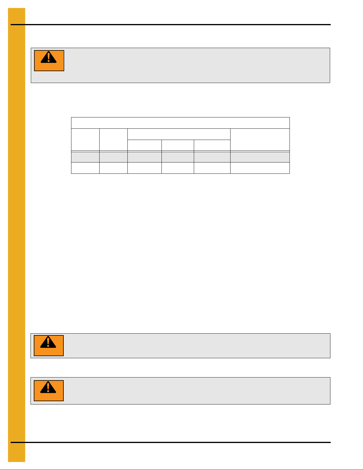
A. Use the Chart below to determine the horsepower required.
NOTE: Sweep is not designed to start under full load.
12" Series II Sweep
Bin
Diameter
131' 5 N/A 20 N/A 63.84' (19.46 m)
135' 5 N/A 20 N/A 65.84' (20.07 m)
Drive HP
Bushel/MT per Hour Horsepower
Length Pivot to End
5000/125 6000/155 7000/180
NOTE: The horsepower recommendations are for augering reasonably dry grain. High moisture grain
(greater than 15%) will require greater power for maximum capacity.
NOTE: Sweep drive and carrier wheels require plates or track over aeration flooring for travel and supports
not supplied with the sweep unit. Contact the installer or flooring provider for possible sources
and details.
B. A magnetic starter should be used to protect the motor when starting and stopping. It should stop the
motor in case of power interruption, conductor fault, low voltage, circuit interruption or motor
overload. The motor must be restarted manually. Some motors have built-in thermal overload
protection. If this is the type of motor being used, use only those with a manual reset.
C. The motor starting controls must be located outside the bin. They must NEVER be installed on the
Series II auger inside the bin.
D. Disconnect and lock out the power before resetting motor overloads.
E. Disconnect and lock out the power before entering the bin.
F. Disconnect and lock out the power before servicing the equipment.
G. Position the reset and motor starting controls so that the operators have full view of the equipment.
WARNING
H. Make sure electric motors are grounded.
WARNING
18 PNEG-751-G2 12" Series II Sweep 131' and 135' Diameter
Page 19
4. General Product Information
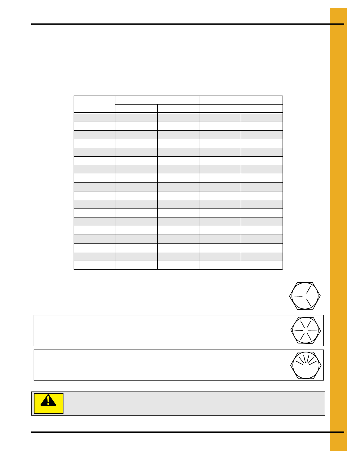
Grade 5 Bolts
Grade 5 bolts are designated by three (3) slash marks on the head.
Grade 8 Bolts
Grade 8 bolts are designated by six (6) slash marks even l y spaced on the he ad of th e bo lt.
Grade 8.2 Bolts
Grade 8.2 bolts are designated by six (6) slash marks on the head in a sunrise pattern.
Under no condition shall any other fasteners be substituted for those supplied
by the manufacturer.
Torque Values to be used when Tightening the Bolts on the Series II Sweep
It takes more force to tighten a 3/4"-10 bolt than to tighten a 1/2"-13 bolt because of its larger diameter. It
also takes more force to tighten a grade 8 bolt than it does to tighten a g rade 5 bolt because of the greater
material strength. A bolt that is waxed or otherwise lubricated requires much less force to tighten. If the
same amount of force is used with a lubricated bolt as with a non-lubricated bolt, the lubricated bolt often
will break.
A suggested initial tightening torque is listed in the Chart below.
Size
1/4"-20 8 ft. lbs. 75 in. lbs. 12 ft. lbs. 9 ft. lbs.
1/4"-28 10 ft. lbs. 86 in. lbs. 14 ft. lbs. 10 ft. lbs.
5/16"-18 17 ft. lbs. 13 ft. lbs. 25 ft. lbs. 18 ft. lbs.
5/16"-24 19 ft. lbs. 14 ft. lbs. 25 ft. lbs. 20 ft. lbs.
3/8"-16 30 ft. lbs. 23 ft. lbs. 45 ft. lbs. 35 ft. lbs.
3/8"-24 35 ft. lbs. 25 ft. lbs. 50 ft. lbs. 35 ft. lbs.
1/2"-13 75 ft. lbs. 55 ft. lbs. 110 ft. lbs. 80 ft. lbs.
1/2"-20 90 ft. lbs. 65 ft. lbs. 120 ft. lbs. 90 ft. lbs.
5/8"-11 150 ft. lbs. 110 ft. lbs. 220 ft. lbs. 170 ft. lbs.
5/8"-18 180 ft. lbs. 130 ft. lbs. 240 ft. lbs. 180 ft. lbs.
3/4"-10 260 ft. lbs. 200 ft. lbs. 380 ft. lbs. 280 ft. lbs.
3/4"-16 300 ft. lbs. 220 ft. lbs. 420 ft. lbs. 320 ft. lbs.
7/8"-9 320 ft. lbs. 320 ft. lbs. 600 ft. lbs. 460 ft. lbs.
1"-8 640 ft. lbs. 480 ft. lbs. 900 ft. lbs. 680 ft. lbs.
1-1/8" - 7 800 ft. lbs. 600 ft. lbs. 1280 ft. lbs. 960 ft. lbs.
1-1/4" - 7 1120 ft. lbs. 840 ft. lbs. 1820 ft. lbs. 1360 ft. lbs.
1-3/8" - 6 1460 ft. lbs. 1100 ft. lbs. 2380 ft. lbs. 1780 ft. lbs.
1-1/2" - 6 1910 ft. lbs. 1460 ft. lbs. 3160 ft. lbs. 2360 ft. lbs.
Grade #5 Assembly Torque Grade #8 Assembly Torque
Dry Lubricated Dry Lubricated
CAUTION
PNEG-751-G2 12" Series II Sweep 131' and 135' Diameter 19
Page 20
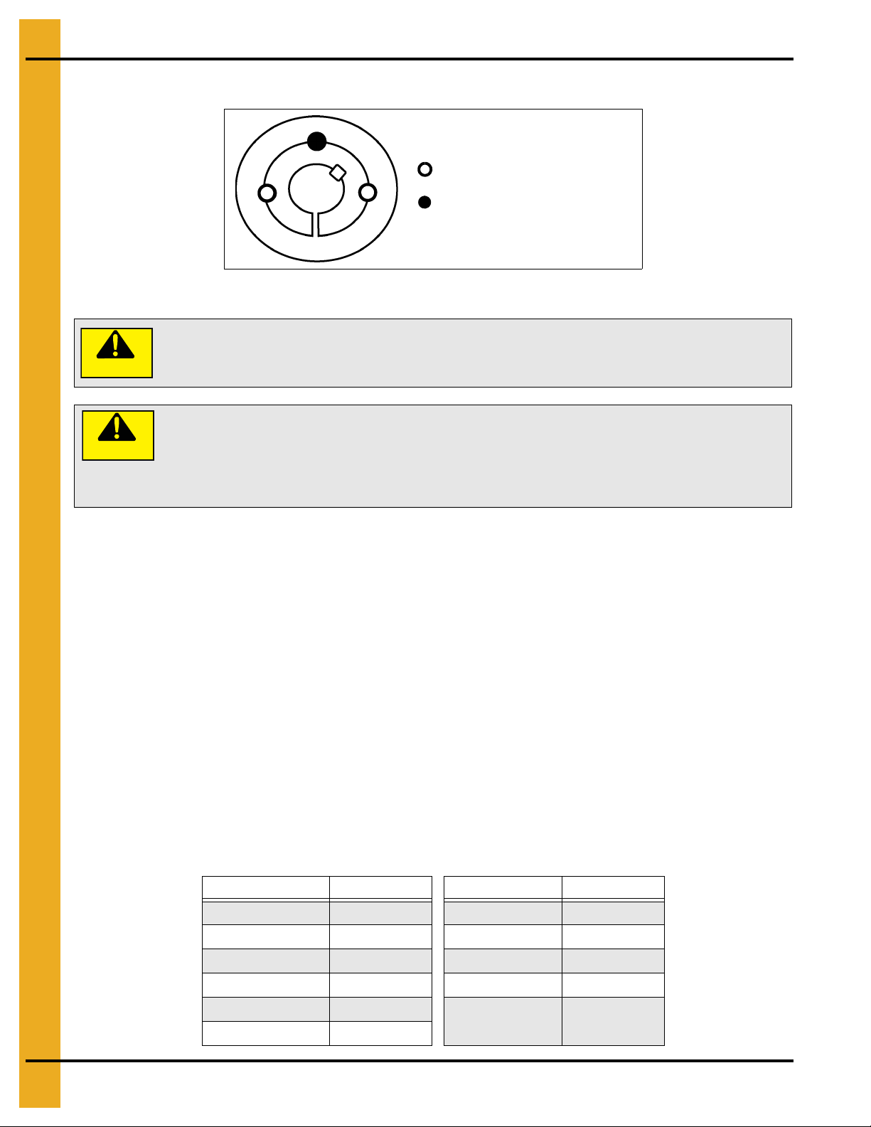
4. General Product Information
Insert set screws to install
Insert set screw to remove
Wedging forces in the bushing saw slot, such as that exerted by a narrow edged
regular screw driver, may damage or break the bushing. This damage would not
be covered under the GSI warranty.
Do not lubricate the bushing taper , bushing bore, hub taper or the shaft. Doing so
could result in breakage of the product.
Do not use worn hex key wrenches. Doing so may result in a loose assembly or
may damage the screws.
CAUTION
Taper-Lock Bushings
Figure 4A Number 1008 to 3030 Bushing
CAUTION
To Install
1. Clean shaft, bore and outside of bushing and hub bore of all oil, paint and dirt. File away burrs.
2. Insert bushing in hub. Match the hole pattern, not threaded holes (each complete hole will be
threaded on one side only).
3. Lightly oil set screws and thread into the half-threaded holes indicated as in Figure 4A.
4. Position the assembly onto the shaft allowing for the small axial movement which will occur during
the tightening procedure.
5. Alternately torque set screws to recommended torque setting listed in the Chart below.
6. To increase the gripping force, hammer the face of the bushing using a drift or sleeve. (Do not hit the
bushing directly with the hammer.)
7. Re-torque the screws after hammering.
8. Re-check the screw torques after the initial run-in and periodically thereafter. Repeat Steps 5, 6
and 7 if loose.
Recommended Installation Wrench Torque
Bushing # lbs.-in Bushing # lbs.-in
1008, 1108 55 3535 1000
1210, 1215, 1310 175 4040 1700
1610, 1615 175 4545 2450
2012 280 5050 3100
2517, 2525 430
20 PNEG-751-G2 12" Series II Sweep 131' and 135' Diameter
3020, 3030 800
6050, 7060, 8065 7820
Page 21
To Remove
1. Remove all screws.
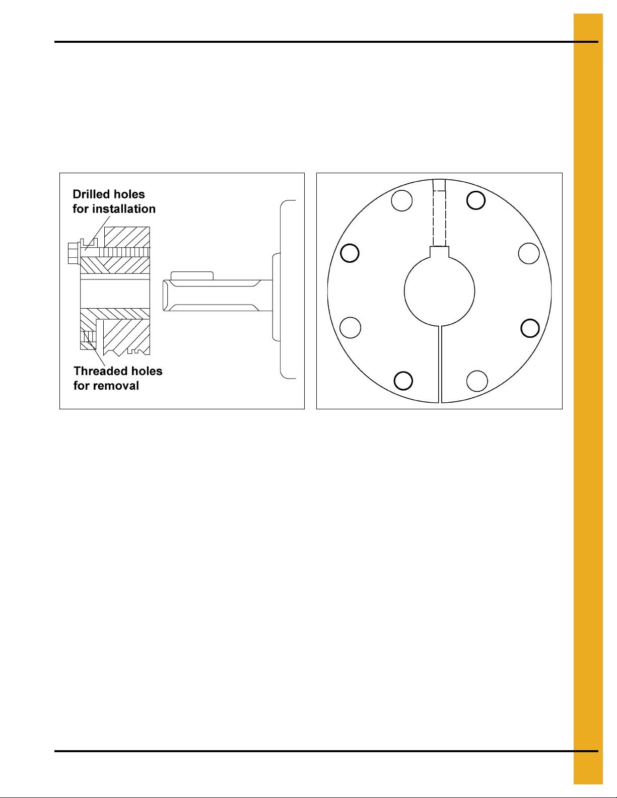
4. General Product Information
2. Insert screws in hole or holes indicated on
the screw(s).
Figure 4A on Page 20
Q-D Bushings - Reverse Mounting
. Loosen the bushing by tightening
Figure 4B
Figure 4C Overhead View of Q-D Bushing
To Install
1. Clean shaft, bore of bushing, outside of bushing and hub bore of all oil, paint and dirt. File
away burrs.
2. Reverse mounting: Place the bushing in hub and insert the cap screws through the drilled holes in
the bushing flange. Tighten the cap screws, finger tight into threaded holes in the hub.
3. With the key on the shaft, slide the loosely assembled unit onto the shaft so that the cap screw
heads are on the outside. Place the unit in the desired position on the shaft.
4. Tighten the cap screws alternately and evenly to the wrench torque specified in the
NOTE: When tightened, there will be a gap of 1/8" to 1/4" between the bushing flange and the hub.
Should this gap be less, either undersize shafting or the wrong bushing shaft size was used.
5. Tighten the set screw (if supplied) over the key to the torque value listed in the Chart on Page 22.
Chart on Page 22
.
PNEG-751-G2 12" Series II Sweep 131' and 135' Diameter 21
Page 22
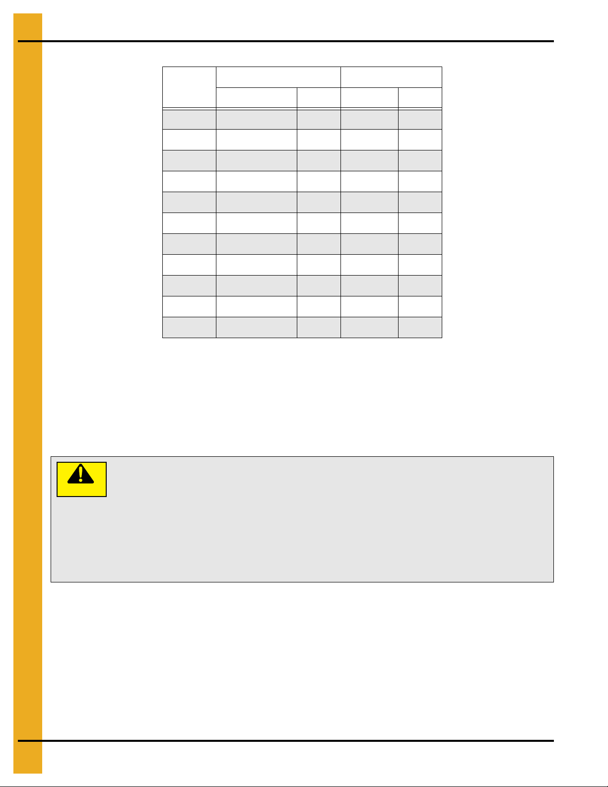
4. General Product Information
Do not lubricate the bushing taper , bushing bore, hub taper or the shaft. Doing so
could result in breakage of the product.
Excessive screw torque may cause damage to either the bushing and/or the
sheave. Uneven pressure on the jack screws may also damage the bushing
flange making removal difficult without damage to the bushing and/or sheave.
Do not use worn hex keys and/or wrenches. Doing so may result in a loose
assembly or may damage the screws.
CAUTION
Recommended Installation Wrench Torque
Bushing
H 1/4"-20 x 7/8" 90 N/A N/A
JA #10-24 x 1" 60 N/A N/A
SH 1/4"-20 x 1-3/8" 108 1/4"-20 87
SDS 1/4"-20 x 1-3/8" 108 1/4"-20 87
SD 1/4"-20 x 1-7/8" 108 1/4"-20 87
SK 5/16"-18 x 2" 180 1/4"-20 87
SF 3/8"-16 x 2" 360 3/8"-16 290
E 1/2"-13 x 2-3/4" 720 3/8"-16 290
F 9/16"-12 x 3-5/8" 900 3/8"-16 290
J 5/8"-11 x 4-1/2" 1620 1/2"-13 620
Cap Screw Key Seat Set Screw
Size lbs.-in Size lbs.-in
M 3/4"-10 x 6-3/4" 2700 1/2"-13 620
To Remove
1. Remove all cap screws.
2. Insert the cap screws into the threaded jack hole or holes.
3. Tighten all the jack screws alternately and evenly beginning with the screw farthest from the bushing
saw slot. Tighten until the bushing grip is released. Slide the unit off the shaft.
22 PNEG-751-G2 12" Series II Sweep 131' and 135' Diameter
Page 23
5. Assembly
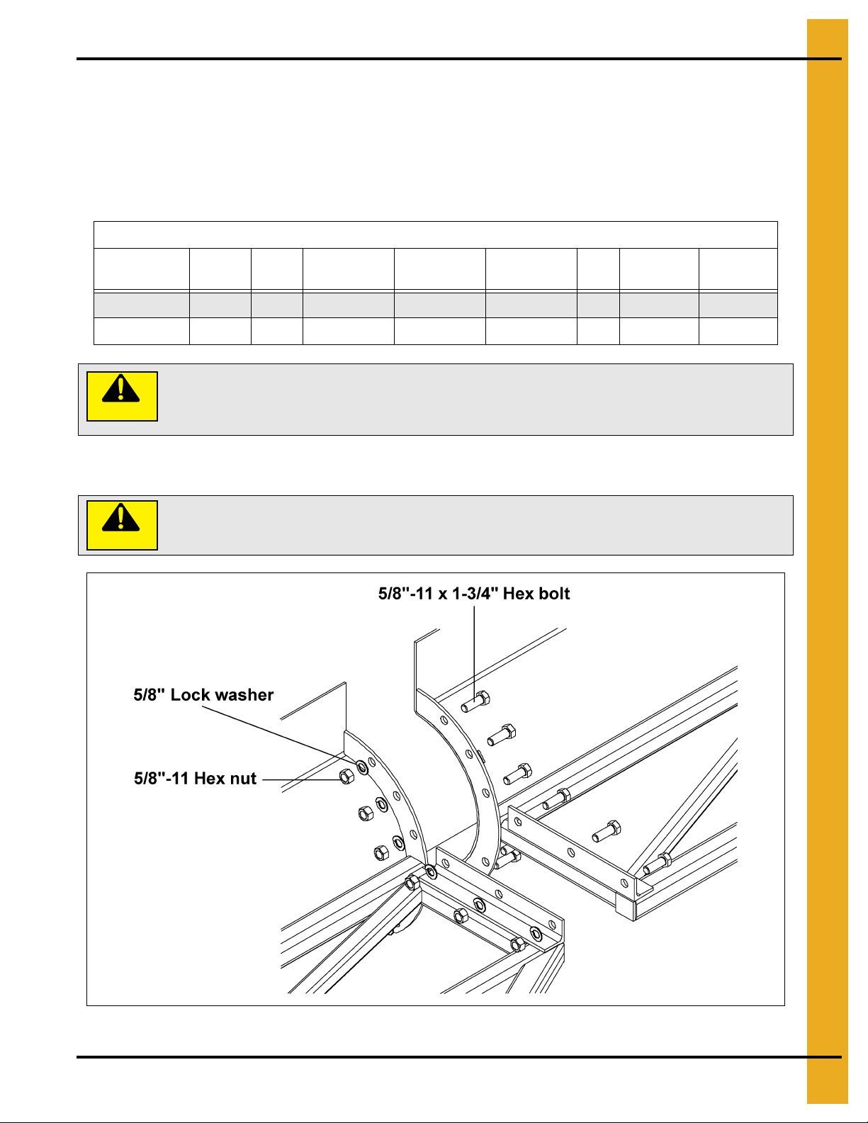
The section sizes are total length given in inches. The head section has 8"
subtracted from the shield length due to the pivot pipe location.
The 12" tail section has 5-1/2" added to the shield length due to the end shaft length.
The bolts MUST be installed as shown in Figure 5A.
Back Shield Assembly
A. The sweep has been broken down into four (4) different section types: the head, intermediate, tail
and extension sections.
NOTE: Use the Chart below to determine the identification and the order of assembly of the individual
sweep sections.
12" Series II Sweep Sections
Bin Diameter
131' 6 136" 144" 144" 60" 144" 137-1/2" 63.84'
135' 6 136" 144" 144" 84" 144" 137-1/2" 65.84'
CAUTION
# of
Sections
Head Intermediate Intermediate Intermediate Tail Extension Pivot to End
B. Use eight (8) 5/8"-11 x 1-3/4" grade 8 hex bolts, lock washers and hex nuts at each
section connection.
CAUTION
Figure 5A
PNEG-751-G2 12" Series II Sweep 131' and 135' Diameter 23
Page 24
5. Assembly
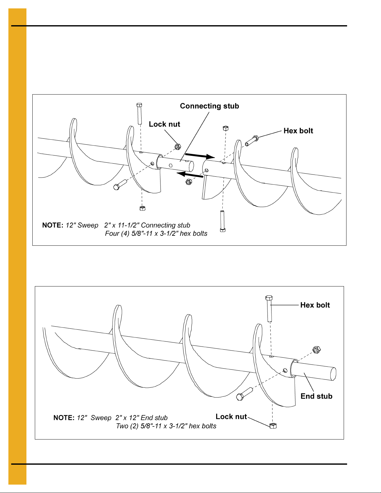
Flighting Assembly
A. Lay out the flight sections in order of assembly starting with the head flight working towards the
tail flight.
B. Using the connecting stubs, bolt the flight sections together with hex bolts and lock nuts. Make sure
the flight ends are in time with each other.
Figure 5B
C. Slide the end stub through the bearing plate on the tail section and into the tail flight securing it with
hex bolts and lock nuts.
Figure 5C
24 PNEG-751-G2 12" Series II Sweep 131' and 135' Diameter
Page 25
5. Assembly
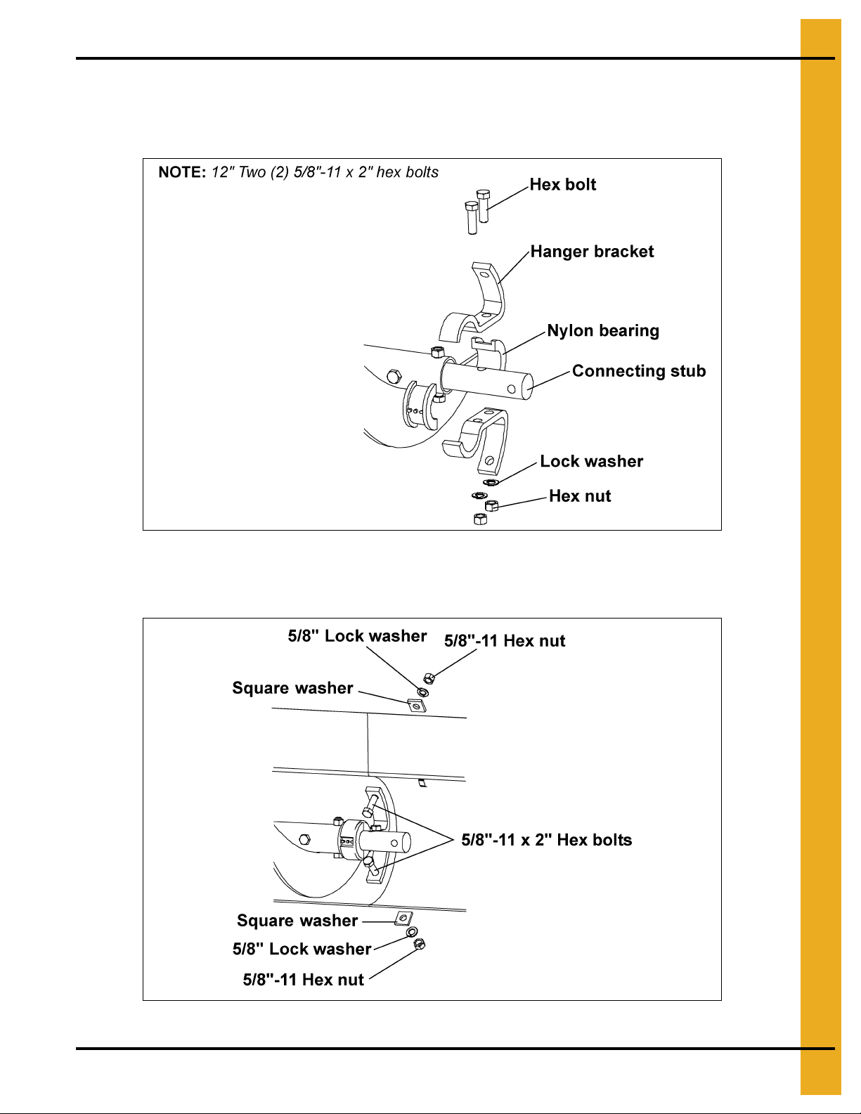
Hanger Bracket Assembly
A. Bolt the nylon bearings and hanger brackets to the connecting stubs using hex bolts, lock washers
and hex nuts as shown in Figure 5D.
Figure 5D
B. Bolt the hanger brackets to the back shields using two (2) 5/8"-11 x 2" hex bolts, two (2) square
washers, two (2) lock washers and two (2) hex nuts as shown in Figure 5E.
Figure 5E
PNEG-751-G2 12" Series II Sweep 131' and 135' Diameter 25
Page 26
5. Assembly
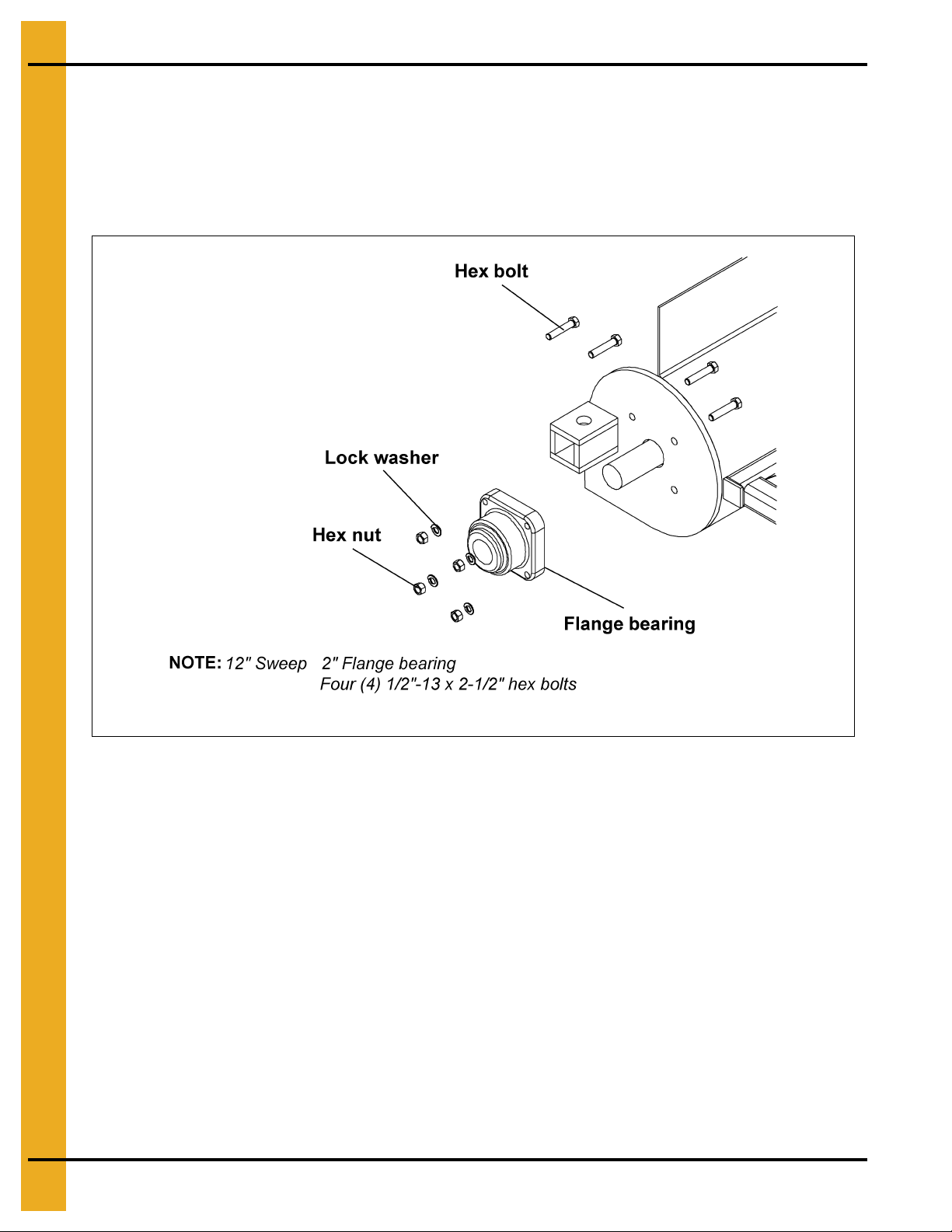
Flange Bearing Assembly
A. Slide the flange bearing onto the end stub and bolt it to the end pla te using hex bolts, lock washers
and hex nuts as shown in Figure 5F.
NOTE: Do not tighten the set screws on the bearing at this time. This can be done after t he gear reducer
is installed.
Figure 5F
Gear Reducer Assembly
A. Slide the output shaft of the reducer through the end plate of the head section and into the end of the
head flight. Secure the reducer output shaft to the head flight with hex bolts and lock nuts.
(See Figure 5G on Page 27.)
B. Bolt the reducer to the end plate of the head section using hex bolts, flat washers and lock washers,
supplied with the reducer. (See Figure 5G on Page 27.)
NOTE: The input shaft of the reducer MUST be to the top of the reducer. Refer to Owner’s manual
supplied with the reducer for proper vent plug, fill plug and drain plug locations.
26 PNEG-751-G2 12" Series II Sweep 131' and 135' Diameter
Page 27
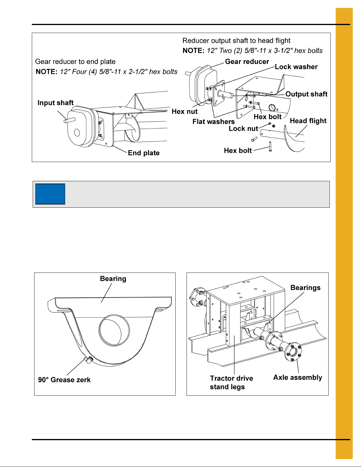
Figure 5G
The gear reducer is NOT filled with oil from the factory. For gear reducer
specifications and oil fill recommendations, refer to lubrication section o n Page 64
of this manual.
5. Assembly
NOTICE
Drive Axle Assembly and Bearing Support
A. Loosen set screws on bearings.
B. Replace standard grease zerks with 90° grease zerks on both bearings. Make sure the 90° grease
zerk is turned as shown in Figure 5H, so the zerks are accessible from the center of the tractor
drive stand.
Figure 5H
C. Slide the axle assembly between the legs of the tractor drive stand as shown in Figure 5I.
D. Rotate the pillow block bearings until the bases are facing up. (See Figure 5I.)
PNEG-751-G2 12" Series II Sweep 131' and 135' Diameter 27
Figure 5I
Page 28
5. Assembly
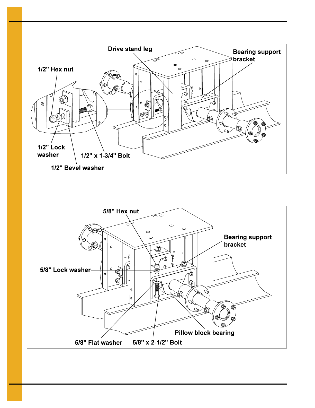
E. Bolt the bearing support brackets to the legs of the tractor drive stand using 1/2" x 1-3/4" bolts,
1/2" lock washers, 1/2" bevel washers and 1/2" hex nuts. (See Figure 5J.)
Figure 5J
F. Attach pillow block bearings to the bearing support brackets using 5/8" x 2-1/2" bolts, 5/8" lock and
flat washers and 5/8" hex nuts. (See Figure 5K.)
Figure 5K
G. Tighten set screws on pillow block bearings.
H. Tighten all hardware.
28 PNEG-751-G2 12" Series II Sweep 131' and 135' Diameter
Page 29
5. Assembly
CAUTION
The gear reducer is NOT filled with oil from the factory. For gear reducer
specifications and oil fill recommendations, refer to Owner’s manual supplied
with the reducer or the lubrication information in the lubrication section on
Page 64 of this manual.
The tractor drive gear reducer has a drain plug in the bottom of the housing. Make
sure the drain plug is flush or slightly under the surface of the mounting face. If it
is not, the plug will not allow the reducer to set flat on the mounting plate and
could cause the motor to seize.
THIS TYPE OF DAMAGE IS NOT COVERED BY THE WARRANTY.
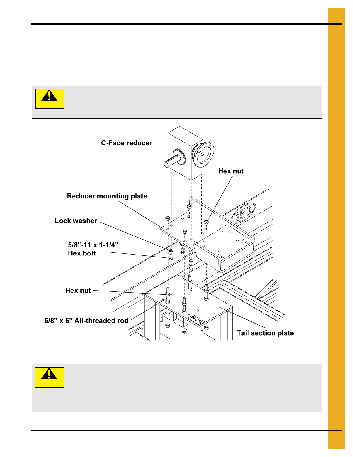
Install Reducer Mounting Plate and Reducer
A. Attach the C-face reducer to the mounting plate using four (4) 5/8"-11 x 1-1/4" hex bolts and
lock washers. (See Figure 5L.)
B. Fasten the reducer mounting plate to the tail section plate using four (4) 5/8"-11 x 6" all-thread rods
and sixteen (16) hex nuts. Adjust the mounting plate as close as possible to the tail section plate.
Figure 5L
CAUTION
PNEG-751-G2 12" Series II Sweep 131' and 135' Diameter 29
Page 30
5. Assembly
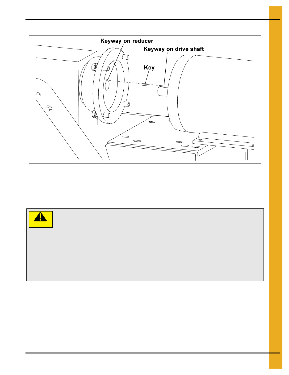
CAUTION
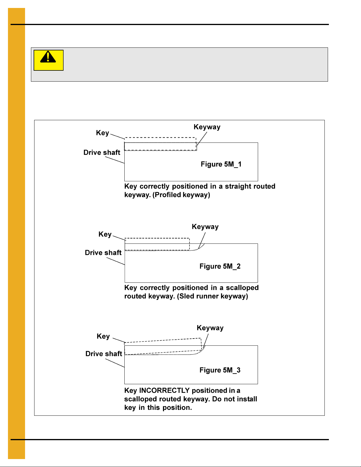
All keys should be parallel to the drive shaft. If the key is not straight (parallel) the
gearbox quill sleeve will crack.
THIS TYPE OF DAMAGE IS NOT COVERED BY WARRANTY.
Key Alignment
A. Place key in keyway on drive shaft.
B. Make sure key is flat (parallel to drive shaft) in keyway as in Figure 5M_1 and Figure 5M_2. NOT
like Figure 5M_3.
Figure 5M
30 PNEG-751-G2 12" Series II Sweep 131' and 135' Diameter
Page 31
5. Assembly
Do not use the motor mounting bolts to pull the motor down to the motor mount
plate. Instead, add shims (GC09838) between the motor feet and the motor mount
plate to fill any gap. If these shims are not used as required, the motor front
bearing may be pushed out of alignment and the motor will lock up. If the gap
seems unusually large, over 1/4", check to make sure the gear reducer is setting
flat on its mounting base. The tractor drive gear reducer has a drain plug in the
bottom of the housing. Make sure the drain plug is flush or slightly under the
surface of the mounting face. If it is not, the plug will not allow the reducer to set
flat on its mounting plate, causing damage to the motor.
THIS TYPE OF DAMAGE IS NOT COVERED BY WARRANTY.
C. Line up keyway on shaft with keyway on reducer and insert shaft into motor. (See Figure 5N.)
Figure 5N
Install Tractor Drive Motor
A. Bolt the C-face motor to the reducer using hex bolts, lock washers and a key. (See Figure 5O on
Page 32.) (See the note on Page 32 for bolt size.)
CAUTION
PNEG-751-G2 12" Series II Sweep 131' and 135' Diameter 31
Page 32

5. Assembly
182TC Frame Four (4) 1/2"-13 x 1-1/4" hex bolts and 1/4" x 1/4" x 1" key
NOTE:
Figure 5O
Guard Assembly
A. Attach the guard plate to the tractor drive stand legs using 3/8" bolts and nuts before attaching the
drive sprocket. (See Figure 5P on Page 33.)
B. Slide the fourteen (14) tooth (teeth N/S) drive sprocket, bushing and key (see key chart on
Page 33 for the size key) onto the output shaft of the reducer, make sure both sprockets line up.
(See Figure 5P and Figure 5P_A on Page 33.)
C. Assemble the bottom chain guard trap to the bottom chain guard weldment using 1/2" x 3" HHCS
bolts, 1/2" split lock washers and 1/2" hex nuts.
D. Attach bottom chain guard weldment to tractor drive stand using 3/8" x 1-1/4" HHCS bolts,
3/8" split lock washers and 3/8" hex nuts. (See Figure 5P on Page 33.)
E. Attach top chain guard assembly to tractor drive stand using 3/8" x 1" bolts, 3/8" split lock washers
and 3/8" hex nuts. (See Figure 5P on Page 33.)
(See Figure 5P on Page 33.)
32 PNEG-751-G2 12" Series II Sweep 131' and 135' Diameter
Page 33

5. Assembly
Key chart
5 HP - 3/8" x 2" Key
Wedging forces in the bushing saw slot, such as that exerted by a narrow edged
regular screw driver, may damage or break the bushing. This damage would not
be covered under the GSI warranty.
CAUTION
PNEG-751-G2 12" Series II Sweep 131' and 135' Diameter 33
Figure 5P
Page 34
5. Assembly
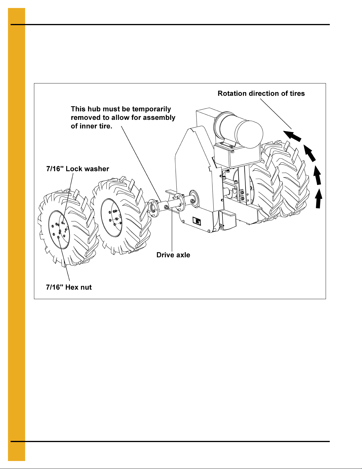
Tractor Wheel Assembly
A. Assemble the tires to the drive axle assembly using twenty (20) 7/16" lock washers and hex nuts.
(See Figure 5Q.)
NOTE: Tires go on backwards as shown in Figure 5Q.
Figure 5Q
34 PNEG-751-G2 12" Series II Sweep 131' and 135' Diameter
Page 35

5. Assembly
CAUTION
Use proper lifting procedures and equipment when lifting the weights. Each
weight weighs 175 pounds.
Weight Placement
A. Place an equal number of weights on each side of the drive assembly on the six inch (6") channels
that are welded to the tail section.
Figure 5R
PNEG-751-G2 12" Series II Sweep 131' and 135' Diameter 35
Page 36

5. Assembly
Channel Extension Kit
A. 131' and 135' Sweeps need an extension kit installed.
B. Attach the center weight weldments to the adjustable center weight channel using eight (8)
1/2" x 1-1/4" bolts, split lock washers and hex nuts. The adjustable center weig ht has thre e (3) sets
of holes for the center weight weldments to adjust the weights. (See Figure 5S.)
Figure 5S
C. Place assembly on top of the back tail section, around the tires. The end of the adjustable center
weight should be placed under the tail frame. (See Figure 5T.)
Figure 5T
D. Fasten assembly to tail section using two (2) 3/8" x 2-7/16" U-bolts, four (4) 3/8" lock washers and
four (4) 3/8" hex nuts.
36 PNEG-751-G2 12" Series II Sweep 131' and 135' Diameter
Page 37

5. Assembly
Motor Jack and Base Assembly
A. Attach the motor mount base assembly to the head section using four (4) 3/4" x 2" bolts,
lock washers and hex nuts. (See Figure 5U.)
B. Attach the motor jack assembly to the motor mount base assembly using four (4) 1/2"-13 x 1-1/2"
bolts, 1/2" flat washers and 1/2" hex nuts.
Figure 5U
PNEG-751-G2 12" Series II Sweep 131' and 135' Diameter 37
Page 38

5. Assembly
Motor bolt
(See chart below for size)
Motor Installation
A. Level the top plate assembly by adjusting the 1" nuts and washers on the adjustment rods.
(See Figure 5V.)
B. Line up the end face of the shafts as closely as possible before bolting motor to mounting plate.
(See Figure 5V-A.)
Figure 5V
C. Fasten the motor to the motor mount using hex bolts, lock washers and hex nuts. (See Motor Bolt
Chart for bolt sizes.)
Motor Bolt Chart
Motor Size Hex Bolt Size Qty
213T 3/8"-16 x 1-1/4" 4
215T 3/8"-16 x 1-1/4" 4
254T 1/2"-13 x 1-3/4" 4
256T 1/2"-13 x 1-3/4" 4
284T 1/2"-13 x 1-3/4" 4
286T 1/2"-13 x 1-3/4" 4
38 PNEG-751-G2 12" Series II Sweep 131' and 135' Diameter
Page 39

Sheave Installation
WARNING
To ensure that the drive is not unexpectedly started, turn OFF and lock out the
power source before proceeding. Failure to observe these precautions could
result in bodily injury.
Wedging forces in the bushing saw slot, such as that exerted by a narrow edged
regular screw driver, may damage or break the bushing. This damage would not
be covered under the GSI warranty.
CAUTION
5. Assembly
Figure 5W
A. Loosely bolt the bushing and large sheave together with the screws provided with the bushing.
B. Slide the bushing and large sheave onto the auger gear reducer input shaft with a key.
(See Figure 5W.)
C. Loosely bolt the bushing and small sheave together with the screws provided with the bushing.
PNEG-751-G2 12" Series II Sweep 131' and 135' Diameter 39
Page 40

5. Assembly
D. Slide the bushing and small sheave onto the motor shaft with a key. (See Figure 5X.)
Figure 5X
E. Align the sheaves with a straight edge to assure proper alignment and tighten the screws on the
bushings. (See Figure 5X.)
F. Carefully install the belts onto the large and small sheaves. (See Figure 5Y on Page 41.)
NOTE: Adjust the hex nuts on the motor mount adjustment rod to attain correct belt tension while
making sure the motor mount is level on both rods. The motor mount must be parallel to the
auger screw to allow for proper sheave alignment.
40 PNEG-751-G2 12" Series II Sweep 131' and 135' Diameter
Page 41

5. Assembly
G. Loosely bolt the bottom belt guard to the motor mount using four (4) 3/8"-16 x 1" hex bolts, flat
washers and lock washers. (See Figure 5Y.)
Figure 5Y
H. Slide the top belt guard over the bottom belt guard as shown in Figure 5Y and tighten bolts.
I. Install belt guard bottom back plate.
J. Slide belt guard bottom pan and bolt into place.
PNEG-751-G2 12" Series II Sweep 131' and 135' Diameter 41
Page 42
5. Assembly
WARNING
All electrical wiring and service work must be performed by a qualified
electrician and must meet all state and local electrical codes.
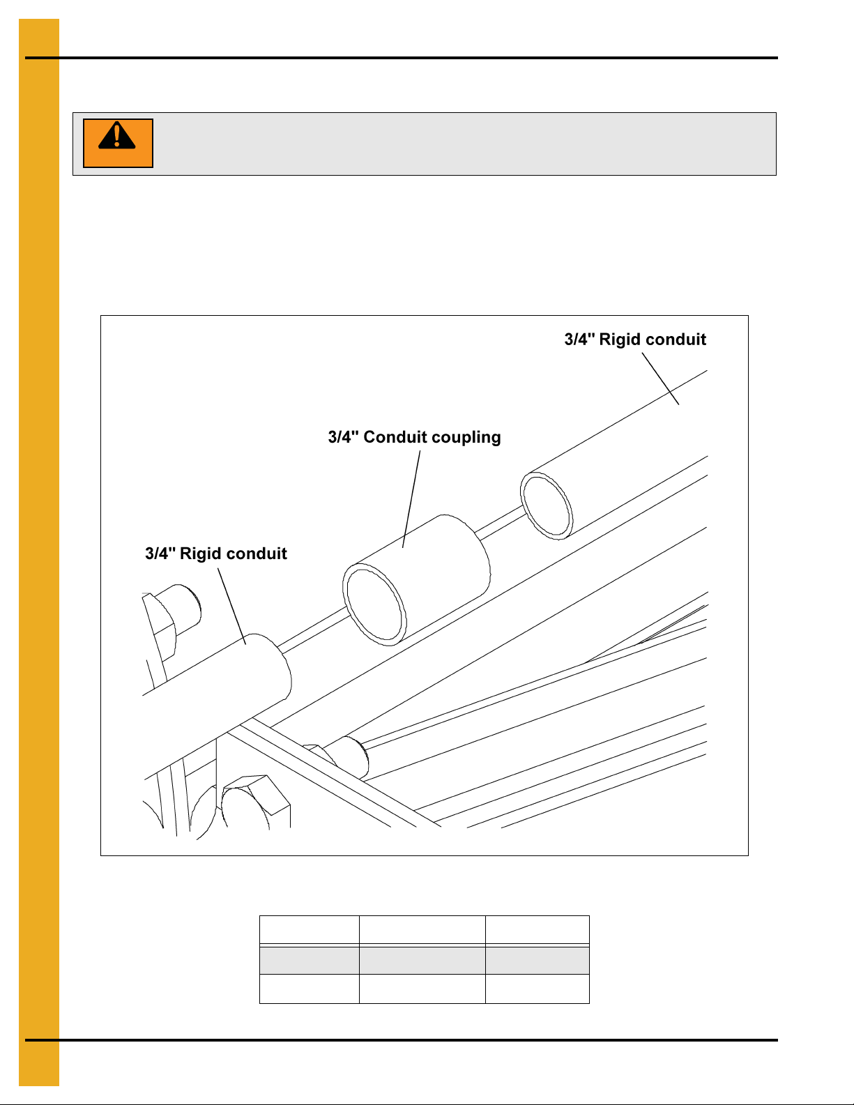
Electrical Assembly
NOTE: See Chart below for the correct size of conduit with the corresponding sweep size.
A. Place the 3/4" rigid conduits in order starting with the head section and working towards the tail or
extension section.
B. Connect the rigid conduit together using one 3/4" conduit coupling between each piece of conduit.
(See Figure 5Z.)
Figure 5Z
Sweep Section Conduit Sizes
Bin Diameter 10' Conduit Pieces Other Pieces
131' 4 1 at 5'
135' 4 1 at 7'
42 PNEG-751-G2 12" Series II Sweep 131' and 135' Diameter
Page 43

5. Assembly
C. Connect the 3/4" x 48" liquid-tight flex conduit to the drive end of the 3/4" rigid conduit using one
3/4" conduit coupling and one 3/4" liquid-tight flex conduit coupling. (See Figure 5AA.)
1. Thread a 3/4" conduit coupling onto the 3/4" rigid conduit. (See Figure 5AA.)
2. Thread a 3/4" flex conduit coupling body onto the 3/4" conduit coupling. (See Figure 5AA.)
3. Slide a 3/4" flex conduit coupling cap onto the 3/4" flex conduit followed by a plastic ring.
(See Figure 5AA.)
4. Thread a steel ring into the 3/4" flex conduit. (See Figure 5AA.)
5. Thread the 3/4" flex conduit coupling cap onto the 3/4" flex conduit coupling body.
(See Figure 5AA.)
Figure 5AA
D. Attach the 3/4" x 12" liquid-tight flex conduit to the other end of the rigid conduit using one 3/4"
conduit coupling and one 3/4" liquid-tight flex conduit coupling. (See Figure 5AB.)
E. Connect the two (2) junction boxes together using the 1" x 4-3/4" conduit nipple. (See Figure 5AB.)
F. Connect the 3/4" x 12" liquid-tight flex conduit to the left junction box using one 3/4" liquid-tight flex
conduit coupling and one 1" to 3/4" reducer bushing. (See Figure 5AB.)
G. Attach the 3/4" x 40" liquid-tight flex conduit to the right junction box using one 3/4" liquid-tight flex
conduit coupling and one 1" to 3/4" reducer bushing. (See Figure 5AB.)
Figure 5AB
PNEG-751-G2 12" Series II Sweep 131' and 135' Diameter 43
Page 44

5. Assembly
H. Feed each of the six (6) 14 AWG stranded wires through the 3/4" rigid conduit assembly and cut
them off, leaving six inches (6") at both the left junction box and drive motor.
I. Feed each of the six (6) 10 AWG stranded wires cord through the 3/4" x 40" liquid-tight flex conduit
and cut four (4) of them off, leaving six inches (6") at both the right junction box and auger motor.
Cut the 10 AWG blue and yellow wires longer so they can be connected to the 14 AWG blue and
yellow wires in the left junction box.
J. Place the 3/4" rigid conduit assembly onto the back frame of the sweep between the connecting
angle and connecting flange.
Figure 5AC
K. Fasten the junction boxes to the mounting plate using two (2) 3/8"-16 x 1-3/8" U-bolts, four (4) lock
washers and hex nuts.
Figure 5AD
44 PNEG-751-G2 12" Series II Sweep 131' and 135' Diameter
Page 45

5. Assembly
L. Attach the 3/4" rigid conduit assembly to the sweep using the 5/16"-18 x 3/4" studs welded to the
sweep using 1" conduit clamps, lock washers and hex nuts.
M. Run the 14 AWG stranded wires into the drive motor and fasten the 3 /4" x 48" liquid-tight flex conduit
to the motor using one 3/4" liquid-tight flex conduit coupling. Some motors may require a reducer
bushing not supplied with the sweep. Connect the leads as required.
Figure 5AE
N. Run the 10 AWG stranded wires into the auger motor and fasten the 3/4" x 40" liquid-tight flex
conduit to the motor using one 3/4" liquid-tight flex conduit coupling. Some motors may require a
reducer bushing not supplied with the sweep. Connect the leads as required.
PNEG-751-G2 12" Series II Sweep 131' and 135' Diameter 45
Page 46

5. Assembly
Jack Support Assembly
NOTE: Be sure to use the spanner bushings, supplied with the caster wheels, between the caster and the
caster plate on each side.
Jack Support (See Figure 5AF below and Figure 5AG on Page 47.)
A. Attach one caster wheel to the jack caster assembly using one 3/4" x 5-1/2" hex bolt, lock washer
and hex nut.
B. Locate the 2" x 2" x 12" tube to the right of each connecting angle and fasten the jack mount
assembly to the sweep frame using one jack mount plate, four (4) 1/2"-13 x 3-3/4" hex bolts, lock
washers and hex nuts.
C. Attach the jack caster assembly to the jack assembly using one pin.
D. Bolt the jack assembly to the jack mount assembly using four (4) 1/2"-13 x 2" hex bolts, lock washers
and hex nuts.
Figure 5AF Current Production Sweep Sh own
46 PNEG-751-G2 12" Series II Sweep 131' and 135' Diameter
Page 47

5. Assembly
Figure 5AG
PNEG-751-G2 12" Series II Sweep 131' and 135' Diameter 47
Page 48

5. Assembly
CAUTION
The center pipe of the pivot assembly MUST be in the center of the bin. If it is
not, the sweep could hit the bin wall.
Center Pivot Installation
A. Center pivot with pivot kit
1. Use the pivot assembly supplied with the sweep pivot kit and cut it to fit, if needed.
2. Feed the multi-conductor cord through the hole in the back of the sweep head section leaving
five feet (5') of cord outside the hole. (See Figure 5AH.)
Figure 5AH
48 PNEG-751-G2 12" Series II Sweep 131' and 135' Diameter
Page 49

5. Assembly
3. Feed the power cord through the pivot tube. (See Figure 5AI.)
4. Align the hole in the back shield with the pivot tube and push the sweep onto the pivot tube.
(See Figure 5AI.)
5. Connect the pivot plate to the back shield using two (2) 1/2"-13 x 1-3/4" hex bolts, flat washers,
lock washers and hex nuts. (See Figure 5AI.)
6. Fasten the pivot rod to the back shield and pivot plate using two (2) 1/2"-13 x 2" hex bolts, lock
washers and hex nuts. (See Figure 5AI.)
7. Screw the 45° grease fitting into the pivot assembly pipe. (See Figure 5AI.)
Figure 5AI
PNEG-751-G2 12" Series II Sweep 131' and 135' Diameter 49
Page 50

5. Assembly
8. Connect the 1" x 48" liquid-tight flex conduit to the pivot tube using one 1" conduit coupling and
one 1" liquid-tight flex conduit coupling. (See Figure 5AJ.)
9. Connect the 1" x 48" liquid-tight flex conduit to one of the junction boxes using one 1" liquid-tight
flex conduit coupling. Connect the leads as required. (See Figure 5AJ.)
10. The customer is to provide proper power cord protection between the pivot assembly and the
sump transition. (See Figure 5AJ.)
Figure 5AJ
11. The multi-conductor power cord can be connected with the 14 AWG/3 wire, 14 AWG/4 wire and
10 AWG/4 wire cords in an explosion proof junction box.
12. Hardwire foot switch to terminal 3 and terminal 4 in control panel.
(See Schematic on Pages 69-72.)
13. Hardwire motor thermostat J-wires to terminal 1 and terminal 2 in control panel. (See Schematic
on Pages 69-72.)
14. Hardwire motors to starters in control panel. (See Schematic on Pages 69-72.)
50 PNEG-751-G2 12" Series II Sweep 131' and 135' Diameter
Page 51

Control Panel Setup
If the meter looks like this:
5. Assembly
Figure 5AK
Follow these instructions:
The control panel is intended for hard wired connections for power in, auger drive motor wiring,
tractor drive motor wiring and the thermal overload wiring for both the auger drive motor and the tractor
drive motor.
If the system that this control panel is designed to have the cables for the auger drive motor and the tractor
drive motor run inside the bin on the floor and exit through the bin door, a plug package is available to
allow the panel to connect to the cords without hard wiring. This package is GC20117. This package is
only standard in the center pin style sweep systems and not in the protected cord center swee p systems.
Control Panel Calibration
Observe the tractor drive motor nameplate and the auger drive motor nameplate.
Record the full load amp (FLA) value for the specific voltage on each motor.
Auger drive motor full load amps: ____
Tractor drive motor full load amps: ____
Switch the disconnect switch on the panel to OFF (not ON).
Unlock and open the control panel.
Adjust the FLA dial screw on the tractor drive motor contactor (M1) and the auger drive motor contactor
(M2) so that the indicator arrowhead is set slightly higher than the full load amp value listed on
the nameplates.
PNEG-751-G2 12" Series II Sweep 131' and 135' Diameter 51
Page 52

5. Assembly
Tractor drive motor contactor (M1) FLA adjustment dial: ____
Auger drive motor (M2) FLA adjustment dial value: ____
Close and lock the control panel.
Switch the disconnect switch on the panel to ON (not OFF).
Initial Display Setup
NOTE: If no keys are activated for 2 minutes, the display returns to the default state without saving any
configuration changes. At each value, after 5 seconds of inactivity, a description of the current
state will scroll across the display.
NOTE: Pressing and hold OK will re turn to the previous menu or return to t he default state without saving
the changed values or parameters.
Press OK on the display unit.
(IN) should be displayed on the unit.
Press or on the display unit until (CURR) is shown (not VOLT, POTM or TEMP).
Press OK.
(RANG) should be displayed on the unit.
Press or on the display unit until 4-20 is shown (not 0-20).
Press OK.
(DEC.P) should be displayed on the unit.
Press or on the display unit until 11.11 is shown (not 1111, 111.1, 1.111 or .1111).
Press OK.
(DI.LO) should be displayed on the unit.
Press or on the display unit until 0 is shown.
Press OK.
(DI.HI) should be displayed on the unit.
The DI.HI value is 2x the value that the FLA dial on the auger drive motor (M2) that was set earlier.
2x FLA dial: ____
Press or on the display unit until the correct value is shown.
Press OK repeatedly until “-----” is displayed. This indicates the programming described above has
been saved.
Make sure no individual is inside the bin.
Make sure the sweep will not contact any obstruction and cause damage.
Have an employee observe the sweep from outside the bin, through the open door.
The person observing the sweep is meant to have control over the safety foot switch.
Have another employee operate the control panel.
52 PNEG-751-G2 12" Series II Sweep 131' and 135' Diameter
Page 53

5. Assembly
Switch the Run Mode switch so that Manual is selected (not Auto).
Switch the Manual Mode switch to Idle (not reverse or forward).
Depress the pedal in the safety foot switch.
Press the Start button on the control panel.
NOTE: If any damage is observed or t here is abnormal operation of the sweep, shut it down immediately.
There are three (3) ways to accomplish this. 1) Remove the pressure on the safety foot switch.
2) Press the Stop button on the control panel. 3) Press in on the Enable/Disable button so that it
collapses appropriately. Switch the disconnect switch on the panel to OFF (not ON). Lock out the
panel before entering the bin to service the sweep.
Observe the no load amps (NLA) displayed on the meter on the front of the panel.
Auger drive motor no load amps: ____
The tractor motor operation (forward and stop) in automatic is dictated by the amp reading on the auger
drive motor.
The tractor drive motor is meant to shut off (idle) when the auger drive motor reaches 90% of the
nameplate FLA.
90% of full load amps: ____
The tractor motor is meant to reactivate (forward) when the auger drive motor reaches 110% of the
no load amps (amperage observed when the auger flight turns freely in absence of grain).
110% of no load amps: ____
Final Display Setup
NOTE: If no keys are activated for 2 minutes, the display returns to the default state without saving any
configuration changes. At each value, after 5 seconds of inactivity, a description of the current
state will scroll across the display.
Press OK repeatedly until RELU is displayed on the unit.
Press or on the display unit until DISP is shown (not PERC).
Press OK.
REL1 should be displayed on the unit.
Press or on the display unit until SET is shown (not SKIP or OFF).
Press OK.
SETP should be displayed on the unit.
Press or on the display unit the 90% of FLA value is shown.
Press OK.
ACT1 should be displayed on the unit.
Press or on the display unit until INCR is shown (not DECR).
Press OK.
PNEG-751-G2 12" Series II Sweep 131' and 135' Diameter 53
Page 54

5. Assembly
HYS1 should be displayed on the unit.
For this control panel hysteresis (HYS1) is measured as the different between 90% of full load amps and
110% of no load amps.
90% of full load amps: ____ minus 110% of no load amps: ____
Press or on the display unit until the correct value is shown.
Press OK.
ERR1 should be displayed on the unit.
Press or on the display unit until DEAC is shown (not HOLD, ACTI or NONE).
Press OK.
ON.DE should be displayed on the unit.
Press or on the display unit until 0 is shown.
Press OK.
OF.DE should be displayed on the unit.
Press or on the display unit until 20 is shown.
Press OK.
REL2 should be displayed on the unit.
Press or on the display unit until OFF is shown (not SET or SKIP).
Press OK.
E.PAS should be displayed on the unit.
Press or on the display unit until NO is shown.
Press OK.
This function will allow the values that were entered to be locked.
NOTE: Using a password will stop access to the menu and parameters. There are two (2) levels of
password protection. Passwords between 0000 and 4999 allow access to the fast set point
adjustment and relay test. (Using this password stops access to all other parts of the menu.)
Passwords between 5000 and 9999 stop access to all parts of the menu, fast set point adjustment
and relay test. (Current set point is still shown.) By using the master password 2008, all
configuration menus are available.
If you select NO, press OK.
If you select YES, N.PAS will be displayed. Press or on the display unit until your password is shown.
Press OK. Document this password.
The password will be necessary if there needs to be changes to many of the configuration values.
54 PNEG-751-G2 12" Series II Sweep 131' and 135' Diameter
Page 55

If the meter looks like this:
NEVER program the “High Amp Set Point” greater than the full load running
amps of the auger motor.
Follow these instructions:
5. Assembly
Figure 5AL
NOTE: In order to fine tune the control panel, the bin must have grain in it.
The Series II Sweep is supplied with adjustable overloads that are not set at the factory. These should be
set slightly higher than the Full Load Amp (FLA) value listed on the motor nameplates.
A. Find the desired “High” Amp and “Low” Amp set points.
1. High Amp Set Point: The Amp load the auger draws when the auger flighting is 90% loaded.
This will turn OFF the tractor drive motor. Initially, set the value to 90% of the Full Load Amps
(FLA) listed on the motor nameplate.
2. Low Amp Set Point: The Amp load the auger motor draws when the auger flighting is 10%
loaded. This will turn ON the drive motor. Initially, set this value to 10% over the Amp draw of the
sweep running empty.
CAUTION
B. Programming the Amp Meter.
PNEG-751-G2 12" Series II Sweep 131' and 135' Diameter 55
Page 56

5. Assembly
Calibration
1. Setting Input
a. Press “PRGM” to “inPut”.
b. Press “ENTER”.
c. Press “PRGM” to “i4-20”.
d. Press “ENTER” to RUN MODE.
2. Setting Setup
a. Press “PRGM” to “SEtuP”.
b. Press “ENTER” to “rdEC”
Use arrow buttons to change the decimal placement. Show .0 Amps.
c. Press “ENTER” to “SETLO”.
d. Press “ENTER”
Value = 0.0
e. Press “ENTER” to “SEtHi”.
f. Press “Enter”
Value = 50.0
Use arrow buttons to change value.
g. Press “ENTER” to “LoCut”.
Press “ENTER”
This value = 0
h. Press “ENTER” to RUN MODE.
56 PNEG-751-G2 12" Series II Sweep 131' and 135' Diameter
Page 57

Operation
1. Setting Presets
a. Press “Pre A”.
b. Press “PRGM”
This value = “High Amp Set Point”.
Use arrow buttons to change value.
c. Press “ENTER”.
2. Setting Relays
a. Press “PRGM” to “rELAYS”.
b. Press “ENTER” to “HYS A”.
c. Press “PRGM”
This value = “High Amp Set Point”-“Low Amp Set Point”
Use arrow buttons to change value.
5. Assembly
d. Press “ENTER” to RUN MODE.
EXAMPLE: Full Load Running Amps = 21 Amps
High Amp Set Point = 20 Amps
Low Amp Set Point = 12 Amps
Then “HYS A” = 8 Amps
And “Pre A” = 20 Amps
NOTE: This is the difference between the High Amp Set Point and the Low Amp Set Point.
[20 Amps-12 Amps = 8 Amps]. Low Amp Set Point is only used to calculate this value.
C. Locking the Amp Meter
1. Locking the Amp meter is not required but prevents the meter from being tampered with once it
is programmed.
2. In RUN MODE, press “LOCK” three (3) times within five (5) seconds.
This value = A number that is easily remembered.
Use arrow buttons to change value.
a. Press “ENTER”.
D. Unlocking the Amp Meter
1. In RUN MODE, press “LOCK” three (3) times within five (5) seconds.
a. Enter the “LoC” value.
Use arrow buttons to change value.
b. Press “ENTER”.
NOTE: It is recommended to write down the “LoC” value and keep it in a safe place in case it
is forgotten.
PNEG-751-G2 12" Series II Sweep 131' and 135' Diameter 57
Page 58
6. Start-Up
WARNING
To ensure that the drive is not unexpectedly started, turn OFF and lock out the
power source before proceeding. Failure to observe these precautions could
result in bodily injury.
DANGER
Failure to perform any or all of these pre-start checks may cause damage to the
equipment and/or cause SERIOUS INJURY or DEATH to those in the work area.
Failure to perform any or all of these pre-start checks may also be a misuse of
the equipment. Any misuse of the equipment may void the warranty.
WARNING
ALWAYS keep ALL guards and shields in place, until all the power is
disconnected and locked out.
CAUTION
Be sure to remove the grain from the drive chain and sprockets. If this is not
done, damage can occur to the drive system.
WARNING
Make certain ONLY trained operators are in the work area before operating or
moving the machine. Two (2) people must always be in position to monitor the
operation of the equipment from outside the bin.
Perform Pre-Start Checks
A. Make sure ALL shields are in place.
B. Inspect the drive unit for any problems or potential problems.
C. Be aware of any emergency shut down procedures. Two (2) people must always be in position to
monitor the operation of the equipment from outside the bin.
D. Before starting the auger for the first time, make sure that all parts are assembled correctly according
to the instructions in this manual.
58 PNEG-751-G2 12" Series II Sweep 131' and 135' Diameter
Page 59

6. Start-Up
CAUTION
DO NOT start or stop the auger while it is under load.
CAUTION
Failures may occur if the auger is run full before it has been “polished” during
the “break-in” period.
CAUTION
NEVER operate the auger empty. Operating augers empty for any length of
time will cause excessive wear. NEVER operate the auger at speeds higher
than recommended.
CAUTION
Be aware of any unusual vibration or noises during the initial start-up and
“break-in” period. If anything unusual is detected, immediately shut down the
auger and disconnect and lock out the power supply before servicing.
Start the Auger
A. Step on the foot switch and press the “Start” button.
B. Run the auger through a “break-in” period if it is being used for the first time or for the first time of
the season.
C. “Polish” the flighting by running the auger at partial capacity until it is smooth, before attempting
full capacity.
PNEG-751-G2 12" Series II Sweep 131' and 135' Diameter 59
Page 60

7. Operation
NOTICE
Gear reducer is shipped without oil. Add the proper amount of the recommended
lubricant before operating. Failure to observe these precautions could result in
damage to or destruction of, the equipment.
Keep out of the bin while the bin sweep auger is in operation. The rapidly moving
sweep auger can cause SERIOUS INJURY or DEATH.
CAUTION
Be alert for any unusual vibrations, noises and the loosening of any fasteners.
If anything unusual is detected, immediately shut down the auger, disconnect and
lock out the power source before servicing.
NEVER enter the bin while the bin sweep is in operation.
NEVER attempt to control the operation of the bin sweep by depressing the
operating controls with shovels, brooms or any other objects.
DO NOT attempt to restrain movement of the bin sweep with ropes, bars or
other devices.
NEVER allow an operator to attempt to manually restrain the bin sweep.
DANGER
Operating the Sweep Auger
DANGER
NOTE: The auger capacity can fluctuate greatly under varying conditions. Moisture content, different
commodities, amount of foreign matter and speeds all play a part in the performance of the auger.
Twenty five percent (25%) moisture may cut capacity by as much as 40% under some conditions.
A. Make certain there are at least two (2) people in the work area to monitor operations at all times.
B. Start the bin unloading equipment before starting the bin sweep auger.
C. Shut down the auger as soon as the bin is empty.
D. Consideration should be given to the proper size auger for any intermittent type operations. When
augers are stopped and restarted under full load, it may result in damage to the auger. Using a larger
diameter auger and reducing its load level will be far better than subjecting a smaller diameter auger
to big loads. If an auger is kept from absolute filling, it will make start-up easier and will convey
more efficiently.
60 PNEG-751-G2 12" Series II Sweep 131' and 135' Diameter
Page 61

7. Operation
Operating the Sweep Auger Control Panel
A. The sweep operates in two (2) different “modes”.
1. Automatic (The auger motor runs and the drive motor runs using the Amp Meter in the
control panel.)
Step on the foot switch and press the “Start” button. The auger motor will turn ON and the drive
motor will turn ON only if the Amp Meter reaches the “Low” set point.
2. Manual (Overrides the Amp Meter and allows the operator to manually move the sweep.)
a. Idle (Allows the auger motor to run, but does not move the sweep forward or reverse.)
b. Forward (Auger motor will run and moves the sweep towards the grain.)
c. Reverse (Stops the auger motor and moves the sweep away from the grain.)
Step on the foot switch and press the “Start” button. The auger motor will turn, but the sweep will not move.
Turn the “Manual” switch to “Forward” and the sweep will move forward towards the grain. Turn the
“Manual” switch to “Reverse” and the auger motor will shut off and move the sweep b ackwards away from
the grain.
The “Start” button MUST be pressed to start the auger motor again.
NOTE: The foot switch MUST be depressed and the thermal protection cord wired in before the sweep
will operate.
PNEG-751-G2 12" Series II Sweep 131' and 135' Diameter 61
Page 62

8. Shut Down
NOTICE
NEVER start the equipment under load. Doing so may cause damage. This type of
damage is considered a misuse of the equipment. Any misuse of the equipment
may void the warranty.
Normal Shut Down
A. Before shutting down the unit, be sure the sumps and unload conveyor are empty.
B. Press the “Stop” button on the control panel.
Emergency Shut Down
A. Know how to shut down the auger in case of an emergency.
B. Step off the foot switch and press the “Stop” button.
C. Disconnect and lock out the power source.
Storage Preparation
A. Be sure the sumps and unload conveyor are empty.
B. Close the sump control gates.
C. Park the sweep behind the intermediate sumps, so that the sumps are on the auger side of
the sweep.
D. Shut down the auger.
E. Make sure all fasteners are tight.
F. After allowing the motors to cool down, cover the motors with the tarps supplied with the sweep.
G. Place blocks under the frame of the sweep to help support the sweep during storage.
62 PNEG-751-G2 12" Series II Sweep 131' and 135' Diameter
Page 63
9. Maintenance
WARNING
ALWAYS shut down and disconnect the power supply before adjusting,
servicing or cleaning the equipment.
NOTICE
ALL SPEED REDUCERS ARE SHIPPED DRY. OIL MUST BE ADDED PRIOR TO
OPERATION. Do not operate the unit without making sure it contains the correct
amount of oil. Do not overfill or underfill with oil or injury to personnel, unit or
other equipment may result.
Do not mix non-synthetic and synthetic oil in the unit.
Maintain the Auger
A. Use caution when repairing or replacing equipment parts.
B. Make sure ALL decals are legible and securely attached to the auger. If necessary, replace them
FREE OF CHARGE by contacting GSI at:
GSI
1004 E. Illinois St.
Assumption, IL. 62510
Phone: 1-217-226-4421
C. Ensure that ALL electric motors, etc., are operating at the proper speed.
D. Make sure ALL electrical wiring is not damaged and that it meets proper wiring codes.
E. Make sure ALL components are in good working condition before use.
NOTICE
PNEG-751-G2 12" Series II Sweep 131' and 135' Diameter 63
Page 64

9. Maintenance
Lubrication
A. Lubrication - Electric Motors
Electric motors supplied for use on Series II Sweeps are properly lubricated at the time of manufacture.
It is not necessary to lubricate them at the time of installation unless the motor has been in storage for
one year or longer. Some motors may be factory lubricated and sealed for the life of the bearings.
Overgreasing the bearings can cause premature failure of the motor. The amount of grease added must
be carefully controlled.
B. Procedure for Lubrication of Electric Motors
1. Stop motor. Disconnect and lock out of service.
2. Follow all safe bin entry procedures and wear all required personal protective equipment.
3. Remove contaminants from grease inlet area.
4. Remove filler and drain plugs.
5. Check filler and drain holes for blockage and clean as necessary.
6. Add proper type and amount of grease. See Chart below and on Page 65 for amount of
lubricant. Too much grease or injecting grease too quickly can cause premature bearing
failure. Use approximately one minute to slowly inject the recommended amount of grease.
7. Wipe off excess grease and replace filler and drain plugs. Do not run motor without the grease
and drain plugs installed.
NOTE: It is very important to keep the grease clean. Mixing dissimilar grease is not recommended.
C. Type of Lubrication
A polyurea mineral oil NGLI grade 2 type grease is to be used for lubrication of the electric motors.
Grease meeting this specification include:
1. Chevron SRI #2
2. Exxon-Mobile Polyrex EM
3. Texaco Polystar RB
D. Frequency of Lubrication
Motors should be relubricated after storage of one year or more or at the beginning of each season.
The following Chart gives the amount of grease to be added.
Lubrication - Electric Motors
Quantity of Grease per Frame Size
For Baldor Brand Electric Motors
NEMA
Frame Size
56C
143TC 0.25 0.14
182TC 0.5 0.28
184TC 0.5 0.28
213T 0.75 0.42
215T 0.75 0.42
254T 1 0.55
256T 1 0.55
284T 1.25 0.69
286T 1.25 0.69
324T 1.5 0.83
Volume
Cu. in. Fluid oz
64 PNEG-751-G2 12" Series II Sweep 131' and 135' Diameter
Page 65

9. Maintenance
For Marathon Brand Electric Motors
NEMA
Frame Size
56C
143TC 0.6 0.3 8.4 2
182TC 0.6 0.3 8.4 2
184TC 0.6 0.3 8.4 2
213T 0.6 0.3 8.4 2
215T 0.6 0.3 8.4 2
254T 1.2 0.61 17.4 3.9
256T 1.2 0.61 17.4 3.9
284T 1.2 0.61 17.4 3.9
286T 1.2 0.61 17.4 3.9
324T 1.5 0.81 23.1 5.2
Cu. in. Ounce Gram Teaspoon
E. Lubrication - Reducers (Gearboxes)
Reducers supplied for use on Series II Sweeps are shipped without lubricant (dry). The proper lubricant
must be added at the time of installation. Over lubrication may cause premature failure of the reducer.
The amount of lubricant must be carefully controlled.
F. Procedure for Initial Filling of Reducers
Volume
1. Disconnect and lock motor out of service. Do not run gearbox without lubricant.
2. Follow all safe bin entry procedures and wear all required personal protective equipment.
3. Remove contaminants from inlet area.
4. Remove filler and oil level fill plugs.
5. Check filler holes for blockage and clean as necessary.
6. Clean the magnetic drain plug if one was supplied.
7. Add proper type of lubricant to fill level or until oil runs out of oil level fill hole.
See the Lubrication Chart on Page 66 for amounts and types of lubricant.
8. Wipe off excess lubricant and replace filler and oil level fill plugs.
NOTE: It is very important to keep the lubricant clean. Mixing dissimilar lubricants is not recommended.
G. Procedure for Changing of Lubricant
1. Stop motor. Disconnect and lock out of service.
2. Follow all safe bin entry procedures and wear all required personal protective equipment.
3. Remove contaminants from inlet and drain area.
4. Remove filler, oil level fill and drain plugs. Drain old lubricant from reducer.
5. Flush reducer with a nonflammable solvent such as lubriplate pure flush or whitmore’s
flushing oil.
6. Clean the magnetic drain plug if installed.
7. Carefully replace drain plug.
8. Add proper type of lubricant to fill level or until oil runs out of oil level fill hole.
See the Lubrication Chart on Page 66 for amounts and types of lubricant.
9. Wipe off excess lubricant and replace filler and oil level fill plugs.
NOTE: It is very important to keep the lubricant clean. Mixing dissimilar lubricants is not recommended.
PNEG-751-G2 12" Series II Sweep 131' and 135' Diameter 65
Page 66

9. Maintenance
H. Frequency of Lubrication
Lubricant should be changed after storage of one year or more or at the beginning of each season.
I. Type of Lubrication
The type and quantity of lubrication required for each type and size of reducer is listed in
the following Chart.
Lubrication - Gearboxes Quantity and Type of Lubricant per Box Size
Hub City (Tractors Driver) Reducer
Volume
Box Series
Pints Worm Top
520 10.6
Lubrication Specification
Mobile SHC634-Synthetic
Or Equal
NOTE: Lubricant capacities are approximate, fill until lubricant starts coming out oil level plug hole.
EPT Browning (Screw Drive)
Box Size Vo lume (Quarts)
107-09 2 Approximately
115-09 2.56 Approximately
203-09 4 Approximately
207-09 6.3 Approximately
215-09 9 Approximately
Lubrication Specification
Mineral Oil Temp 15°F-60°F Temp 50°F-125°F
AGMA 4 AGMA 5
Mobile Oil Company DTE Oil Extra Heavy DTE-Oil BB
Synthetic Oil Temp 0°F-90°F Temp 15°F-125°F
AGMA 4 AGMA 5
Mobile Oil Company Mobile SHC 629 Mobile SHC 630
66 PNEG-751-G2 12" Series II Sweep 131' and 135' Diameter
Page 67

9. Maintenance
J. Lubrication - Bearings, Casters and Jacks
The flange bearings, pillow block bearings and casters supplied for use on Series II Sweeps are
shipped from the factory lubricated. From time to time a small amount of the proper lubricant must be
added. Over lubrication may cause premature failure of the components.
K. Procedure for Lubricating Flange and Pillow Block Bearings
1. Disconnect and lock motors out of service.
2. Follow all safe bin entry procedures and wear all required personal protective equipment.
3. Remove contaminants from the grease zerk and surrounding area.
4. Add proper type of lubricant. See the lubrication chart on Page 68 for types of lubricant.
5. Wipe off excess lubricant.
NOTE: It is very important to keep the lubricant clean.
L. Procedure for Lubricating Casters
1. Disconnect and lock motors out of service.
2. Follow all safe bin entry procedures and wear all required personal protective equipment.
3. Remove contaminants from the grease zerk and surrounding area.
4. Add proper type of lubricant. See the lubrication chart on Page 68 for types of lubricant.
5. Wipe off excess lubricant.
NOTE: It is very important to keep the lubricant clean.
M. Procedure for Lubricating Jacks
1. Disconnect and lock motors out of service.
2. Follow all safe bin entry procedures and wear all required personal protective equipment.
3. Lubricate the gears using the grease zerk at the top of the jack. Rotate the jack handle to
distribute the grease.
4. Lightly grease the inner tube of the jack using the same type of grease.
5. Apply a light weight oil to the handle unit at both sides of the tube.
6. Apply a light weight oil to the small hole at the upper end of the jack to lubricate the nut and
screw assembly.
N. Frequency of Lubrication
The tractor drive pillow block bearings and the end flange bearing, along with the casters, should be
lubricated after each use of the Series II Sweep. If possible, lubricate all the components at the
beginning of each season or after long term storage.
PNEG-751-G2 12" Series II Sweep 131' and 135' Diameter 67
Page 68

9. Maintenance
Too much oil will cause overheating an d too little will result in gear failure. Check
oil level regularly.
NOTICE
Extreme pressure (EP) lubricants are not recommended for average operating
conditions. Failure to observe these precautions could result in damage to or
destruction of the equipment.
Under Extreme operating conditions, such as rapid rise and fall of temperatures,
dust, dirt, chemical particles, chemical fumes or oil sump temperature above
200°F, the oil should be changed every 1 to 3 months, depending on severity
of conditions.
If the unit is used in the food or drug industry (including animal food) consult
the petroleum supplier for recommendations on lubricants which meet the
specifications of the FDA, USDA and/or other authoritative bodies having
jurisdiction. Standard lubricants are not suitable for these applications or
these industries.
WARNING
Oil, housings and other components can reach high temperatures during
operation and can cause severe burns. Use extreme care when removing
lubrication plugs and vents while servicing the unit.
O. Type of Lubrication
The type of lubrication required, for each component, is listed in the following Chart.
Lubrication - Bearings, Casters and Misc. Equipment
Type of Lubricant
Equipment Lubrication Specification
Tractor Drive Pillow Blocks Shell Oil Company Alvania #2 (or equivalent)
End Flange Bearing Shell Oil Company Alvania #2 (or equivalent)
Nylon Flight Bearings None Required None Required
Head End Casters Shell Oil Company Alvania #2 (or equivalent)
Jack Casters Shell Oil Company Alvania #2 (or equivalent)
Jacks Shell Oil Company Alvania #2 (or equivalent)
NOTICE
NOTICE
CAUTION
NOTE: The pour point of the lubricant selected should be at least 10°F lower than the expe cted minimum
ambient starting temperature. Extreme pressure (EP) lubricants are not recommended for average
operating conditions.
68 PNEG-751-G2 12" Series II Sweep 131' and 135' Diameter
Page 69

10. Control Panel Diagrams
Control Panel Schematic (460/3/60) Pre-June 2010
NOTE: All wires are to be 18 AWG unless otherwise noted.
PNEG-751-G2 12" Series II Sweep 131' and 135' Diameter 69
Page 70

10. Control Panel Diagrams
Grain Sweep Schematic Post-June 2010 (S2PFA)
70 PNEG-751-G2 12" Series II Sweep 131' and 135' Diameter
Page 71

10. Control Panel Diagrams
Grain Sweep Schematic Post-June 2010 (S2PFB)
PNEG-751-G2 12" Series II Sweep 131' and 135' Diameter 71
Page 72

10. Control Panel Diagrams
Grain Sweep Schematic Post-June 2010 (S2PFC)
72 PNEG-751-G2 12" Series II Sweep 131' and 135' Diameter
Page 73

11. Troubleshooting
Problem Possible Cause Solution
1. Sweep does not run.
2. Low capacity.
3. Sweep does not move
around the bin.
1. Foot switch may not be actuated.
2. Overloads may be tripped. 2. Reset the overloads.
3. Adjustable overloads not set correctly.
1. The auger may not be fully loaded.
2. The auger is moving too slowly.
1. The control panel may not be in
“automatic mode”.
2. The amp meter is not properly adjusted.
3. The drive chain may be broken. 3. Repair the drive chain.
1. The auger may have foreign materials
in it.
1. Make sure the foot switch is depressed
and the switch is operating properly.
3. Set overload to 10% over the value
listed on motor nameplate for full
load amps.
1. Make sure the grain is flowing into the
auger, making it fully loaded.
2. Check the auger speed. Low
capacity results from speeds slower
than recommended.
1. Turn the switch to “automatic mode”.
2. Set the amp meter so the running amps
of the auger motor turns ON the
drive motor.
1. Remove the foreign material.
4. The sweep is vibrating.
2. The hanger bearings may be worn. 2. Replace the hanger bearings.
3. The flight connections may be loose. 3. Tighten all of the flight connecting bolts.
4. The flighting may be worn.
4. Replace all the flighting sections that
are worn.
PNEG-751-G2 12" Series II Sweep 131' and 135' Diameter 73
Page 74
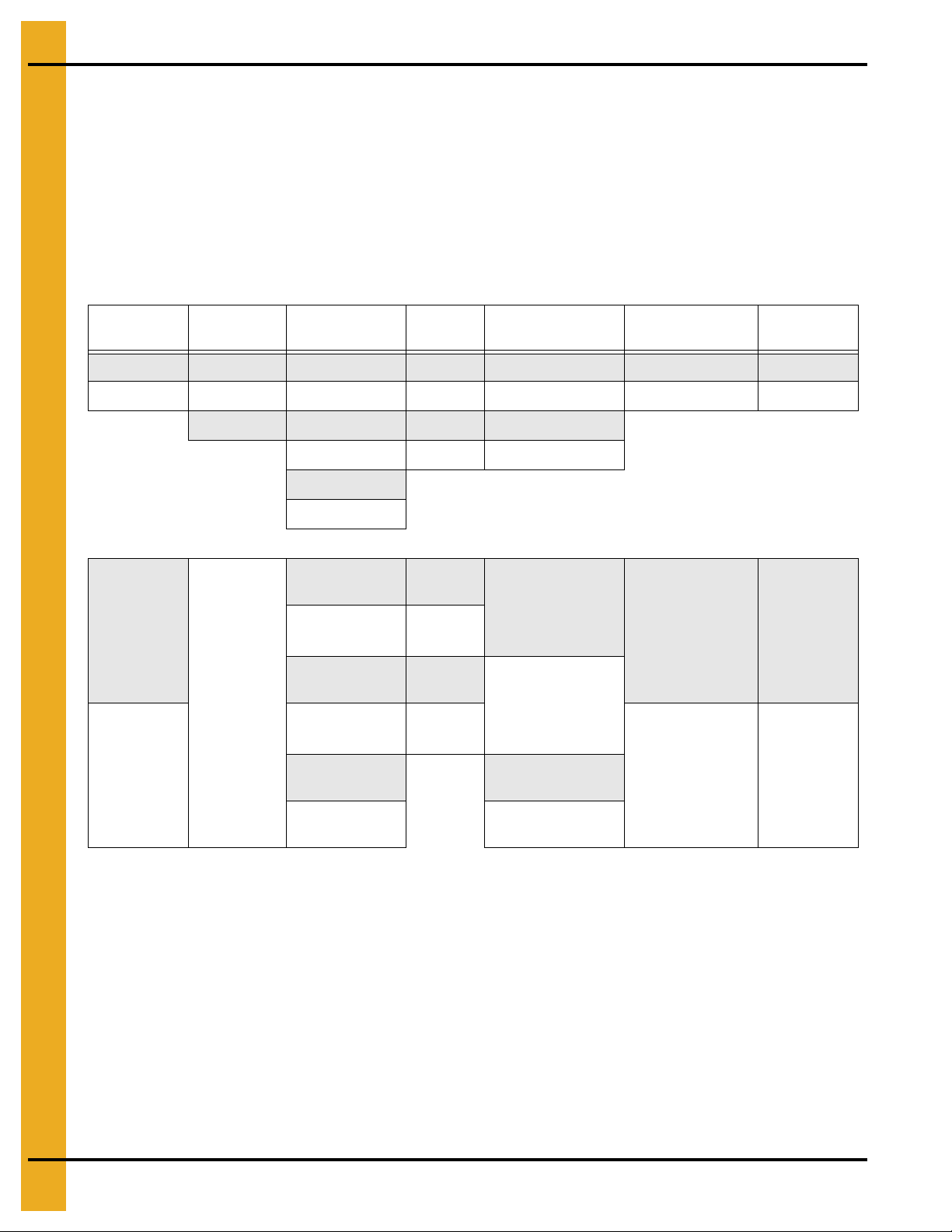
11. Tr oubleshooting
FAQs
Who do I contact for parts or service?
Contact your dealer. If your unit was purchased direct from GSI, contact your inside sales person.
What is/where do I find the model number of my sweep?
The model number of your sweep can be found on your quote or invoice. A space is provided at the
front of your manual to record this number.
The model number code is as follows:
Style Diameter
H 36' -12 - 5 F
K *** -12 - 6 G P T 1
135' -12 - 7 J B
Standard
H
Welded
Truss
(36'-135')
GSI Standard
Bin Diameter
Knockdown
Truss (Not
K
Available
above 120')
Size and
Capacity
-16 - 8 K Q
-16 - 9
-16 - 10
-12 - 5 12" Flight
and 5000 BPH
-12 - 6 12" Flight
and 6000 BPH
-12 - 7 12" Flight
and 7000 BPH
-16 - 8 16" Flight
and 8000 BPH
-16 - 9 16" Flight
and 9000 BPH
-16 - 10 16" Flight
and 10000 BPH
Voltage Option 1 Option 2 Option 3
F 380/3/50
G 575/3/60
J 415/3/60
K 460/3/60
(Standard) Pin
Center Sump
Design, for Cables
on the Floor (Not
Through Sump)
Pivot Plate Center
Sump Design, for
P
Center Protected
Cables or Center
Slip Ring
Control Panel
B
Not Included
QSame as P + B
(Standard - 36'120') V-Belt Flight
PT, (Standard135') HT200
Flight PT
(36'-120') HT200
T
Flight PT
(Standard)
GSI Flight
PT HP
Increased
1
Flight PT HP
74 PNEG-751-G2 12" Series II Sweep 131' and 135' Diameter
Page 75

11. Troubleshooting
Do I want to buy a pivot or a standard sweep? What is the difference?
The following Figure 11A is of a 12" pivot sweep head end weldment and a 12" standard sweep head
end weldment. There are very few differences between the two. The standard head weldment has the
female pivot tube welded to the drive end of the unit. Two (2) plate braces and one pipe brace support
this tube. The pivot head weldment has a lug welded to the underside of the motor mount plate. This
lug is for attachment of the sweep pivot rod assembly. There is a large hole in the rear plate for the
center support tube assembly to pass through. Next to the large hole is a slot that the center support
mounts to.
Figure 11A
How complete is the Series II Sweep?
With the exception of a few electrical connectors, all components required to assemble your sweep
are included.
How level does my floor need to be for the sweep to operate properly?
The top edge of the sump hopper and the top edge of the “X” brace support must be level with the
floor. The floor must be level within 3/4" plus or minus, preferably less. Any high or low points must be
gradually sloped. The change in elevation should be no more than 3/4" over 60".
Where should the center pivot pin be located?
The center pin or pivot pipe must be in the center of the bin. If it is not, the sweep could hit the bin wall.
There should be between 2" and 14" of clearance between the end of the sweep and the closest
obstruction (bin wall, stiffeners, etc.).
How round must my bin be for the sweep to operate properly?
Diameter tolerances are limited by foundation limits and sweep operation as well as structural issues.
For 72' diameter and larger bins, the overall tolerance would be plus or minus 1-1/4" on the radius, plus
or minus 1" on 42'-66' diameter bins and plus or minus 3/4" on 30'-39' bins.
PNEG-751-G2 12" Series II Sweep 131' and 135' Diameter 75
Page 76

11. Tr oubleshooting
How large of an opening do I need for a standard flow (15000 BPH) center sump?
If installing a GSI supplied sump shell with collector ring, the opening must be 42-1/2" x 42-1/2" x 30"
deep for the 12" sweep.
The sump hopper supplied by GSI was designed with sufficient clearance around the collector ring
housing to allow grain to gravity flow through the hopper and be carried away by the material handling
equipment below it. 42-3/4" is the maximum opening size to allow rolling clearance for the casters
assembled to the head end jack. If the sump is made smaller, grain flow may decrease to an
unacceptable level.
Figure 11B
The open area of this sump is misleading. The collector ring housing sticks down into the sump,
blocking off a portion of the flow. Also, the sweep covers about one quarter of the opening at the top.
We use 75% of the theoretical flow around the housing for the actual flow.
What intermediate sump spacing do I need? Why?
It is required to install the intermediate sumps on a maximum of 10' centers where the sweep will be
parked during storage. The first intermediate sump should be placed a maximum of 10' on center from
the center sump and the end sump should be no farther than 4' from the bin wall. The extra sumps will
help clean out the grain in front of the sweep, reducing the start-up load. Doing this will save labor
dollars and hours of work to dig out the sweep and will help the sweep during start-up. The sweep is
not designed to start-up when submerged in material. The sweep should be parked behind the
intermediate sumps with the sumps on the auger side of the sweep.
Do I need to clean out around the end of the sweep prior to starting it up?
Enough material must be removed from around the tractor drive and the screw drive units to allow
access to the motor/drive covers. Both the chain drive and the belt drive must be free of grain before
and during operation.
76 PNEG-751-G2 12" Series II Sweep 131' and 135' Diameter
Page 77

11. Troubleshooting
Where do I park the sweep before I fill the bin with grain?
There is a section in the manual called “Storage Preparation on Page 62”. The section says to “Park
the sweep behind the intermediate sumps, so that the sumps are on the auger side of the sweep”. The
sweep should not completely cover the inside sump hole (the one closest to the center sump). You will
have to clean out around the tractor drive and the jack wheels before operation.
Where do I find the track dimensions?
The wheel path dimensions are listed at the front of the Owner’s manual. Your dealer also has a copy
of the path dimensions in his price book. The head jack wheels are not listed on the chart. These are
always 34" from the center of the bin. The area around the center sump must be kept clear for the
head jack wheels to roll.
What do I need to hook electrical power to the Series II Sweep?
The Series II Sweep is designed to operate using 460 volt 3 phase 60 cycle power. The voltage must
be within plus or minus 4% for proper operation. Voltages outside of this range may cause excessive
power draw or other operating problems. Please contact the factory for applications outside of
these parameters.
The power must be locked out before servicing the equipment, entering the bin or resetting the
motor overloads.
The wiring to the GSI supplied control box is the owner’s responsibility and is not included with
the sweep.
Electrical controls and wiring should be installed by a qualified electrician. The conductor cables
should comply with the National Electrical Code and any state or local codes which may apply.
How does the Series II Sweep operate?
The Series II Sweep is designed with a small controller in the control panel door to monitor the load on
the screw motor. It automatically shuts the tractor drive OFF when the screw motor reaches a
percentage of the motor nameplate full load amperage. As the material clears the screw, the amperage
lowers until it reaches a set value and the tractor drive turns back on and moves the screw into the
material. The customer must program the set points into the controller and this setup is fully explained
in the Owner’s manual. We usually start the high set point at approximately 90% of full load amps
(FLA) listed on the motor nameplate and the low set point at 60% of the FLA.
Can I use the same control panel for different size sweeps?
If the different size sweeps use the sa me size motors, the same control panel can be used for dif ferent
sweeps. The controller must be reprogrammed for each sweep.
Why does the controller need to be located at the bin door?
The control panel MUST be mounted OUTSIDE the bin near the door for safety reasons. It must be
located so the operator has a full view of the equipment. It must NEVER be installed inside the bin.
Why do I need a foot switch?
The foot switch has to be plugged into the control panel and depressed before the sweep is
operational. It has a 10' cord so the sweep can only be monitored from OUTSIDE the bin.
PNEG-751-G2 12" Series II Sweep 131' and 135' Diameter 77
Page 78

11. Tr oubleshooting
Can I just run my sweep in the manual mode?
The Series II Sweep is designed to run in the automatic mode. If the sweep is run in the manual mode,
either of the motors may overheat and/or become damaged. Also, excessive amounts of material may
spill over the back board of the sweep.
How do I set my overloads?
The overloads for both motors are adjustable and are not set at the factory. The overload inside the
control panel has a small, usually yellow, dial with numbers on it. Record the full load running amp
value listed on the nameplate attached to each motor. Increase the full load amp value by 10% and
set this number on the overload dial. If the adjustable overloads are set too low, the motors will shut
down as soon as a load is put on them. Disconnect and lock out the power before resetting the
motor overloads.
When do I program my controller?
Initially the sweep should be tested in the manual mode. If it operates properly, then move on to try the
automatic mode.
How do I program my controller for automatic mode?
The Owner’s manual has a detailed set of instructions describing the setup of automatic mode. The
final programming must be performed with material in the tank.
Why does not the auger run while tractor drive is in reverse?
This is a safety feature of the Series II Sweep.
Can I get the unit to reverse while in automatic?
No. This is another safety feature of the Series II Sweep.
What do I do if I encounter any operational problems?
Disconnect and lock out the power before servicing the equipment, entering the bin or resetting the
motor overloads. Look through the troubleshooting section to identify any problems.
There does not seem to be any power to my sweep. What do I do?
Check to be sure the foot switch is depressed. The foot switch has a 10' cord so t he sweep can only be
monitored from OUTSIDE the bin.
The thermal protection cord must be connected before the sweep will operate.
Your electrician should check to make sure there are no loose or shorted connections or wires. It is
possible that one of the components failed after it was tested in our plant and needs to be replaced. A
jobsite electrician can isolate any malfunctioning components. Each fuse should also be checked and
replaced if necessary.
The sweep must be wired according to the Owner/Installation manuals.
78 PNEG-751-G2 12" Series II Sweep 131' and 135' Diameter
Page 79

11. Troubleshooting
The overload for the screw drive keeps tripping. What do I do?
The overloads for both motors are adjustable. These are not set at the factory prior to delivery and
installation. The overload inside the control panel has a small, usually yellow, dial with numbers on it.
Record the full load running amp value listed on the nameplate attached to each motor. Increase the
full load amp value by 10% and set this number on the overload dial. If the adjustable overloads are set
too low , the motors will sh ut down as soon as a load is pu t on them. Disconnect and lock ou t the power
before resetting the motor overloads.
Check the incoming power at the control box. The Series II Sweep is designed to operate using
460 volt 3 phase 60 cycle power. The voltage must be within plus or minus 4% for proper operation.
Voltages outside of this range may cause excessive power draw or other operating problems. Please
contact the factory for applications outside of these parameters.
Check the incoming power at the motor. Check for balanced phases. If the loads are not properly
balanced between leads, disconnect the motor and check the power leads. By using this method, we
can tell if the imbalance is caused by the motor or is from the incoming power.
The sweep must be wired according to the Owner/Installation manuals.
My tractor drive seems to start and stop too often in automatic. What do I do?
The HYS A (High set point minus low set point) may be set with too large a number. To get maximum
capacity from the sweep, this number should be set as small as possible and not have grain spill over
the sweep backboard.
My controller quits operating. What do I do?
Check to make sure the controller has power. Each of the fuses should be checked and replaced
if required.
If the controller is functioning, it may need to be reprogrammed. Programming instructio ns are included
in the manual that shipped with the sweep. The controller can be damaged by large power fluctuations
or lightning strikes.
My sweep is not operating as well as it did the last time I used it. What do I do?
If the type of material or the density (moisture) of the material changes, the controller set points may
need to be adjusted for maximum output.
Is there any maintenance I need to perform on the electrical system?
None of the electrical components require maintenance. Be sure to disconnect and lock out the power
before servicing the equipment, entering the bin or resetting the motor overloads.
Does any part of the Series II Sweep need lubrication?
The fluid level of each of the gear reducers must be checked before operation. These reducers may
have been shipped dry and require oil before operation.
A complete lubrication section is provided in the Owner’s manual, which shows the type and amount of
lubricant to be used and which components need to be lubricated.
What maintenance should I perform and how often?
Follow the lubrication instructions in the Owner’s manual. Also visually inspect the sweep
before operation.
PNEG-751-G2 12" Series II Sweep 131' and 135' Diameter 79
Page 80

11. Tr oubleshooting
What should I visually inspect?
Starting from the drive end of the sweep:
Inspect the head jack, caster mounting channel and head casters. Look for any bent or
damaged components.
Inspect the motor covers. They should be in good shape and should be used properly. If the covers are
not used, the material will work its way into the motor cooling slots and when the sweep is started, the
motor fan and housing will be destroyed.
Inspect the belt guard for damage. Make sure there is no material inside the belt guard. The drain pan
at the bottom of the guard can be used if required.
Inspect the drive belts, sheaves and bushings. Check the belts for proper tension. Sheaves and
bushings should be tight.
Inspect the intermediate jacks for any broken or damaged components. Check the jack wheels for
damage. The jacks should operate freely.
Inspect each of the screw flight bearings and hangers for damage. Check to see if the bearings need to
be replaced. All hardware should be tight.
Inspect the screw flights for damage or excessive wear. Check to see if the screws are rusted or pitted.
Inspect the end bearing for damage.
Inspect the end caster (if one was originally supplied) to confirm it is working properly or if it needs to
be replaced.
Inspect the tractor drive chain guard for damage. Make sure there is no material (grain) inside the
chain guard. If there is any material (grain), drain pan which is at the bottom of the guard can be used
to empty the guard.
Inspect the drive chain for damage and proper lubrication. Check for proper tension and confirm the
sprockets and bushings are tight.
Inspect the tractor drive tires for damage or tread wear. Be sure the lug nuts are tight and tires are
installed with the tread direction as shown in the manual.
Inspect the bearings for damage or excessive wear. Replace if necessary.
Inspect the tractor drive motor and gear reducer for damage or excessive wear.
Make sure all hardware is tight.
Inspect the sweep structure for damaged or bent components.
80 PNEG-751-G2 12" Series II Sweep 131' and 135' Diameter
Page 81

1. Main Auger Components - (See Pages 82-83.)
2. Flight Components - (See Page 84.)
3. End Bearing Components - (See Page 85.)
4. Auger Drive Components - (See Pages 86-87.)
5. Drive Assembly - (See Pages 88-89.)
6. Tractor Chain Guard Parts - (See Page 90.)
7. Motor Mount Jack and Base Assembly (GC09993) - (See Page 91.)
8. Jack Supports - (See Pages 92-93.)
9. Control Panel Components (S2PFA) - (See Page 94.)
12. Parts List
10. Control Panel Components Post-June 2010 (S2PFA) - (See Pages 96-97.)
11. Control Panel Components Post-June 2010 (S2PFB) - (See Pages 98-99.)
12. Control Panel Components Post-June 2010 (S2PFC) - (See Pages 100-101.)
13. Weight Extension Kit (GC12311) - (See Page 102.)
PNEG-751-G2 12" Series II Sweep 131' and 135' Diameter 81
Page 82

12. Parts List
Main Auger Components
82 PNEG-751-G2 12" Series II Sweep 131' and 135' Diameter
Page 83

Main Auger Components Parts List
Ref # Part # Description
1 GC07078 S2 Sweep Head Section 12" x 144" Pvt
2 GC07068 S2 Sweep Intermediate Section 12" x 144"
3 GC07061 S2 Sweep Intermediate Section 12" x 60"
3 GC07063 S2 Sweep Intermediate Section 12" x 84"
4 GC20013 S2 Sweep Tail Section 12" x Extension
5 GC07272 S2 Sweep Extension Section 12" x 132"
6 GC06465 S2 Sweep Head Flight 12" x 140-3/4"
7 GC06466 S2 Sweep Intermediate/Tai l Flight 12" x 142"
8 GC06622 S2 Sweep Intermediate Flight 12" x 58"
8 GC06624 S2 Sweep Intermediate Flight 12" x 82"
9 GC06467 S2 Sweep Extension Flight 12" x 130"
12. Parts List
10 GC03798 Conduit 3/4" Rigid x 60"
10 GC06877 Conduit 3/4" Rigid x 84"
1 1 S-6197 Conduit 3/4" Rigid x 120"
12 GC07523 Conduit 3/4" Flex x 12"
13 GC04862 Conduit 3/4" Flex x 40"
14 GC03800 Conduit 3/4" Flex x 48"
N/S S-6196 Conduit Coupling x 3/4"
N/S S-6198 Conduit Coupling Flex x 3/4"
N/S S-8411 Conduit Clamp 1 Hole ZN 1"
N/S TFC-0054 Conduit Flex 90° Elbow x 3/4"
N/S S-8513 Conduit Reducer Bush 1" to 3/4"
N/S GC07744 Conduit Nipple 1" x 4-3/4"
N/S 1EL0428 Connector Cord (8/4 Cable) 3/4" x 7/8"
N/S S-4284 Connector Cord (10/4 Cable) 5/8" to 3/4"
N/S S-4283 Connector Cord (14/4 Cable) 1/4" to 5/8"
15 GC07521 Junction Box-Expl Proof
PNEG-751-G2 12" Series II Sweep 131' and 135' Diameter 83
Page 84

12. Parts List
Flight Components
12" Flight Connection Components
12" Flight Connection Components Parts List
Ref # Part # Description Qty
1 Intermediate Shroud - 3/16" x 12" N/A
2 GC06000 Hanger Bearing Bracket for 12" Sweep 2
3 S-4329 Bolt, HHCS 5/8"-11 x 2" ZN Grade 8 2
4 S-3208 5/8" Split Lock Washer 2
5 S-8423 Square Flat Washer 11/16" ZN 2
6 S-4110 Hex Nut 5/8"-11 ZN Grade 5 2
7 S-8399 Bolt, HHCS 5/8"-11 x 2" ZN Grade 5 2
8 S-3208 5/8" Split Lock Washer 2
9 S-7597 Hex Nut 5/8"-11 ZN 2
10 GC07701 Nylon Bearing: 2" 2
11 GC03956 2" Coupling Stub 1
12 S-7011 Bolt, HHCS 5/8"-11 x 3-1/2" ZN Grade 8 4
13 S-6494 Lock Nut 5/8"-11 ZN Grade 5 Deformed 4
84 PNEG-751-G2 12" Series II Sweep 131' and 135' Diameter
Page 85

End Bearing Components
12. Parts List
End Bearing Components Parts List
Ref # Part # Description
1 KD-PBA0004 Flange Bearing 2" End Cap (12" Sweeps)
2 GC03957 End Stub 2" x 14-7/8" (12" Sweeps)
PNEG-751-G2 12" Series II Sweep 131' and 135' Diameter 85
Page 86

12. Parts List
Auger Drive Components
86 PNEG-751-G2 12" Series II Sweep 131' and 135' Diameter
Page 87

Auger Drive Components Parts List
Ref # Part # Description
1 N/A Motor: XPFC, Class 2 Group F and G
1 712-3-XP 7.5 HP - 213T Frame
1 MHC60010X 10 HP - 215T Frame
1 MHC60015X 15 HP - 254T Frame
1 MHC60020X 20 HP - 256T Frame
1 MHC60025X 25 HP - 284T Frame
2 GC09993 Motor Mount Assembly with Jack
2 GC09986 Motor Mount Base Assembly
2 GC09992 Motor Jack Assembly
3 GC03436 Swivel Caster 1-1/2" x 4"
4 N/A Reducer: with CEMA Adapter and Output Shaft
4 GC11363 115SMTP05-2"
12. Parts List
4 GC09809 115SMTP09-2"
4 GC11364 203SMTP05-2"
4 GC09587 203SMTP09-2"
4 GC11597 207SMTP09-2"
4 GC09810 115SMTP09-3"
4 GC09588 203SMTP09-3"
4 GC09589 207SMTP09-3"
4 GC09591 215SMTP09-3"
5 N/A Belt
6 GC09770 Belt Guard Assembly, Top
7 GC09764 Belt Guard Assembly, Bottom
8 N/A Sprocket
9 N/A Bushing
N/S G C03654 Motor Cover 39" x 35" x 20"
10 GC09762 Belt Guard Bottom Back Plate
11 GC09759 Belt Guard Bottom Pan
12 N/A Belt Guard Motor Specific Plate
12 GC09875 184T Frame
12 GC09876 213/215T Frames
12 GC09877 254/256T Frames
12 GC09878 284/286T Frames
12 GC09879 324T Frame
PNEG-751-G2 12" Series II Sweep 131' and 135' Diameter 87
Page 88

12. Parts List
Drive Assembly
88 PNEG-751-G2 12" Series II Sweep 131' and 135' Diameter
Page 89

12. Parts List
Drive Assembly Parts List
Ref # Part # Description Qty
1 GC12273 Reducer, 524 Model, 50:1 Style B, 182TC Frame 1
2
GC09932
3 GC12268 Sprocket, #100 14 Tooth 1
4 S-9180 Square Key, 3/8" x 2" 1
5 GC12270 Bushing, 1-3/4" 2012 Taper Lock 1
6 GC12263
7 GC03476 Tire, Mounted, 12-8 x 23" Right Hand Tractor Tread-Foam Filled 2
8 GC06508 Tire, Mounted, 12-8 x 23" Left Hand Tractor Tread-Foam Filled 2
N/S GC12208 175 Lbs. Counterweight 12
N/S GC12272 Drive Axle Assembly - Bolt on Hubs (N/S) 1
11 GC12255 Top Chain Guard Assembly 1
12 GC12283 Bearing Support Bracket 2
13 S-3883 Bolt, HHCS 1/2"-13 x 1-3/4" 8
14 S-236 1/2" Split Lock Washer ZN 8
15 S-3729 Hex Nut 1/2"-13 ZN YDP Grade 5 8
16 S-8429 Bolt, HHCS 5/8"-11 x 2-1/2" 4
Motor: XPFC, Class 2 Group F and G,
5 HP 1760 RPM 460/3/60 184TC Frame with Feet (380V Only)
S2 Sweep Tractor Drive Motor Mount 182TC
1
1
17 S-858 Flat Washer 5/8" 4
18 S-3208 5/8" Split Lock Washer 4
19 S-4110 Hex Nut 5/8"-11 ZN Grade 5 4
20 S-9242 5/8" Beveled Washer 4
21 GC12279 Bearing, Pillow Block, 2-1/4" I.D. 2
22 GC12267 Sprocket, #100 45 Tooth for Axle 1
23 GC12269 Bushing, 2-1/4" 3020 Taper Lock 1
24 GC12271 Bolt-On Drive Axle 1
25 GC12282 Bolt-On Hub Assembly 4
26 GC03811 Square Key, 1/2" x 2-1/4" 1
N/S GC12274 Roller Chain #80 x 71" 1
N/S GC11777 Connecting Link #80 1
N/S GC11778 Offset Link #80 1
N/S GC03653 Motor Cover 57" x 35" x 20" 1
PNEG-751-G2 12" Series II Sweep 131' and 135' Diameter 89
Page 90

12. Parts List
Tractor Chain Guard Parts
Tractor Chain Guard Parts List
Ref # Part # Description Qty
1 GC12255 Top Chain Guard Assembly 1
2 GC12276 Bottom Chain Guard Assembly 1
3 GC12277 Bottom Chain Guard Weldment 1
4 GC10047 Bottom Chain Guard Trap 1
5 S-236 1/2" Split Lock Washer ZN 2
6 S-3729 Hex Nut 1/2"-13 ZN YDP Grade 5 2
7 S-7722 Bolt, 1/2"-13 x 3" 2
8 GC10035 Guard Plate 1
9 S-7469 Bolt, HHCS 3/8"-16 x 1" 4
10 S-1054 3/8" Split Lock Washer Zinc 10
11 S-456 3/8"-16 Hex Nut Zinc YDP Grade 5 10
12 S-2071 Bolt, HHCS 3/8"-16 x 1-1/4" 6
90 PNEG-751-G2 12" Series II Sweep 131' and 135' Diameter
Page 91

Motor Mount Jack and Base Assembly (GC09993)
12. Parts List
Motor Mount Jack and Base Assembly (GC09993) Parts List
Motor Jack Assembly (GC09992)
Ref # Part # Description Qty
1 GC09991 Jack Housing Assembly 1
2 GC09479 Jack/Caster Mount Base 1
3 GC10461 Jack-without Outer Housing 1
4 GC03436 Swivel Caster 1-1/2" x 4" 2
5 S-1054 3/8" Split Lock Washer Zinc 8
6 S-2071 Bolt, HHCS 3/8"-16 x 1-1/4" 8
7 S-456 3/8"-16 Hex Nut Zinc YDP Grade 5 8
8 S-8441 Jack Clevis Pin 1
Motor Mount Base Assembly (GC09986)
Ref # Part # Description Qty
11 GC09984 Frame Weldment 1
12 GC09756 Top Plate Assembly 1
13 GC09755 Adjuster Assembly 2
14 GC09757 Pivot Shaft 2
15 S-240 Hex Nut, 1"-8 4
16 S-7835 Flat Washer, 1" 4
17 S-7241 Cotter Pin, 1/8" x 1-1/4" 4
18 S-8760 Bolt, 1/2"-13 x 1-1/2" 4
19 S-2120 Flat Washer, 1/2" 4
20 S-3729 Hex Nut 1/2"-13 ZN YDP Grade 5 4
PNEG-751-G2 12" Series II Sweep 131' and 135' Diameter 91
Page 92

12. Parts List
Jack Supports
92 PNEG-751-G2 12" Series II Sweep 131' and 135' Diameter
Page 93

12. Parts List
Jack Supports Parts List
Ref # Part # Description Qty
1 GC06974 Caster Wheel 3" x 8" Diameter x 3/4" Axle 1
1.1 S-6638 Bolt, HHCS 3/4"-10 x 5-1/2" ZN Grade 8 1
1.2 S-233 Split Lock Washer, 3/4" ZN 1
1.3 S-234 Hex Nut, 3/4"-10 ZN Grade 5 1
2 GC08507 S2 Sweep Jack Caster Assembly 1
3 S-8441 Jack Clevis Pin 1
4 GC07934 S2 Sweep 7000# Jack Assembly 1
4.1 S-7528 Bolt, HHCS 1/2"-13 x 1-1/2" ZN Grade 5 4
4.2 S-236 1/2" Split Lock Washer ZN 4
4.3 S-7510 1/2"-13 Hex Nut Zinc Grade 2 4
5 GC07839 Jack Mount Assembly 1
5.1 S-8400 Bolt, HHCS 1/2"-13 x 3-3/4" ZN Grade 5 4
5.2 S-236 1/2" Split Lock Washer ZN 4
5.3 S-7510 1/2"-13 Hex Nut Zinc Grade 2 4
6 GC07926 S2 Sweep Jack Mount Plate Assembly 1
7 GC07931 S2 Sweep Jack Truss Assembly - 12" 1
7.1 S-7528 Bolt, HHCS 1/2"-13 x 1-1/2" ZN Grade 5 4
7.2 S-236 1/2" Split Lock Washer ZN 4
7.3 S-7510 1/2"-13 Hex Nut Zinc Grade 2 4
N/S GC08627 BOP: Jack Kit (Contains all above parts less wheel) 1
PNEG-751-G2 12" Series II Sweep 131' and 135' Diameter 93
Page 94

12. Parts List
Control Panel Components (S2PFA)
Control Panel Components (S2PFA) Parts List
Ref # Part # Description Qty
1 GC06958 Standard Round Push Button Plastic Flush Green 1
2 GC03659 Standard Round Push Button Plastic Flush Red 1
3 GC20181 2 Position Sel (XB5AAD25) 1
4 GC20182 3 Position Sel (XB5AD53) 1
5 GC07585 Panel, S2 Sweep Amp Meter Device 1
6 AS-0721 40 mm Enable/Disable Stop 1
94 PNEG-751-G2 12" Series II Sweep 131' and 135' Diameter
Page 95

NOTES
PNEG-751-G2 12" Series II Sweep 131' and 135' Diameter 95
Page 96

12. Parts List
Control Panel Components Post-June 2010 (S2PFA)
96 PNEG-751-G2 12" Series II Sweep 131' and 135' Diameter
Page 97

12. Parts List
Control Panel Components Post-June 2010 (S2PFA) Parts List
Ref # Part # Description Qty
1 GC20205 Circuit Breaker 3P 600V 150A (SQD JJL36150) 1
2 GC20206 Motor Starter Base 12A Reversing (SQD LU2B12BL) 1
3 GC20207 Adv Control Unit-CL20-3 PH 3-12A 24VDC (SQD LUCD12BL) 1
4 GC20208 Motor Starter Base 32A (SQD LUB32) 1
5 GC20209 Adv Control Unit-CL20-3 PH 8-32A 24VDC (SQD LUCD32BL) 1
6 GC20210 Motor Load Indication Module 4-20 mA (SQD LUFV2) 1
7 AS-0732 Fuse Holder 600V 30 Amp 2 Pole, CC Fuse (SQD DFCC2) 1
8 AS-0758 End Clamp (PHNX 1201413) 8
9 AS-0759 Terminal Block (PHNX 3004362) 5
10 GC20211 Power Supply 24VDC 3A (SQU ABL8RPS24030) 1
11 AS-0729 600V CC TD Fuse (FRZ ATQR1) 2
PNEG-751-G2 12" Series II Sweep 131' and 135' Diameter 97
Page 98
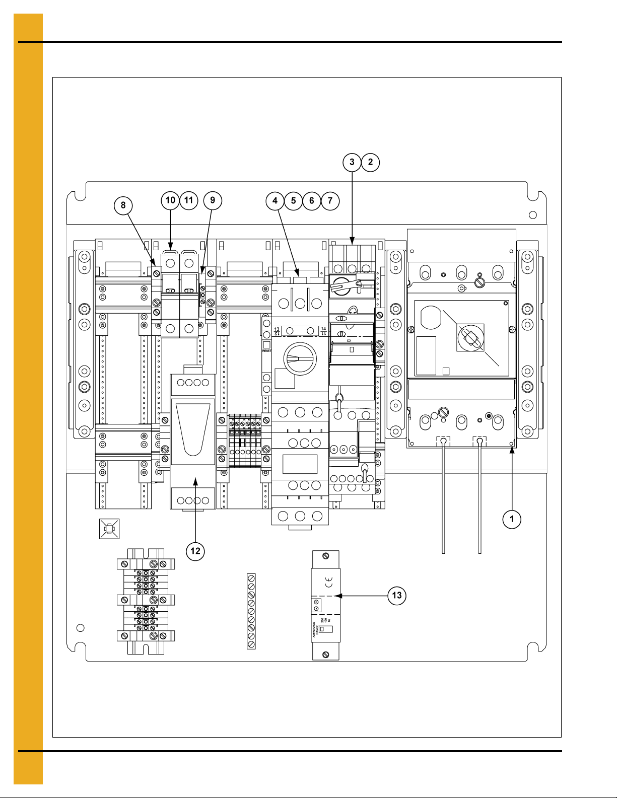
12. Parts List
Control Panel Components Post-June 2010 (S2PFB)
98 PNEG-751-G2 12" Series II Sweep 131' and 135' Diameter
Page 99

12. Parts List
Control Panel Components Post-June 2010 (S2PFB) Parts List
Ref # Part # Description Qty
1 GC20205 Circuit Breaker 3P 600V 150A (SQD JJL36150) 1
2 GC20206 Motor Starter Base 12A Reversing (SQD LU2B12BL) 1
3 GC20207 Adv Control Unit-CL20-3 PH 3-12A 24VDC (SQD LUCD12BL) 1
4 GC20212 Motor Starter/Protector (SQD GV3P40) 1
5 GC20213 Auxiliary Contact Block (SQD GVAM11) 1
6 GC20214 Contactor Non-Reversing 40 Amp 24VDC Coil (SQD LC1D40ABD) 1
7 GC20215 Auxiliary Contact Block (SQD GVAE1) 1
8 AS-0758 End Clamp (PHNX 1201413) 8
9 AS-0759 Terminal Block (PHNX 3004362) 5
10 AS-0732 Fuse Holder 600V 30 Amp 2 Pole, CC Fuse (SQD DFCC2) 1
11 AS-0729 600V CC TD Fuse (FRZ ATQR1) 2
12 GC20211 Power Supply 24VDC 3A (SQD ABL8RPS24030) 1
13 GC20217 Current Transformer with 4-20 mA Output (HAW H721HC) 1
PNEG-751-G2 12" Series II Sweep 131' and 135' Diameter 99
Page 100

12. Parts List
Control Panel Components Post-June 2010 (S2PFC)
100 PNEG-751-G2 12" Series II Sweep 131' and 135' Diameter
 Loading...