

Page 1
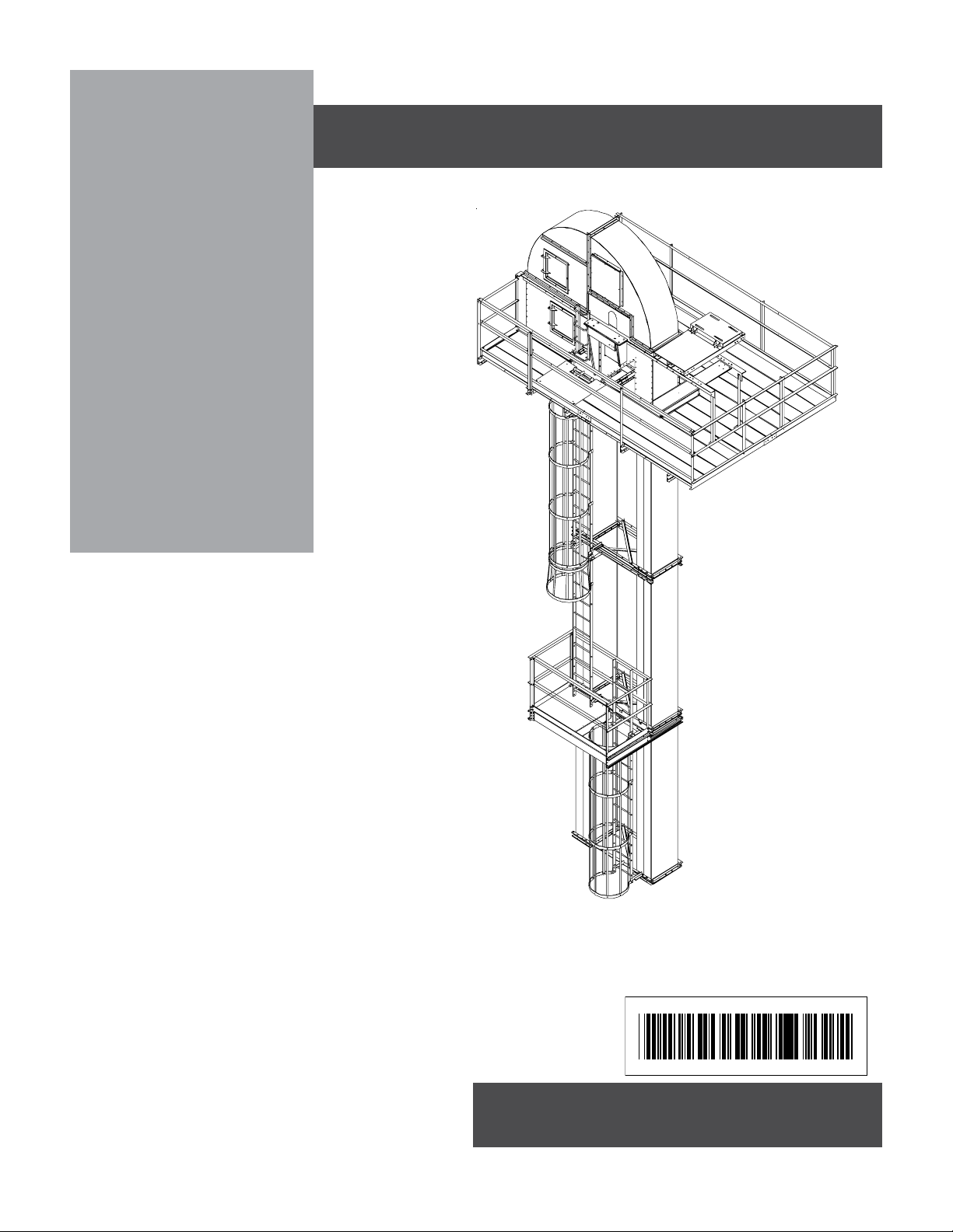
42" - 48"
Platform,
Safety Cage, &
Rest Platform
for Bucket Elevators
Installation Manual
PNEG-739
Revision Date: 10-16-2006
PNEG-739
Page 2

Page 3
Introduction
READ THIS MANUAL carefully to learn how to
properly use and install equipment. Failure to do
so could result in personal injury or equipment
damage.
INSPECT the shipment immediately upon arrival.
The Customer is responsible for ensuring that all
quantities are correct. Report any damage or
shortages by recording a detailed description on
the Bill of Lading to justify the Customer’s claim
from the Transport Firm. Our responsibility for
damage to the equipment ends with acceptance
by the delivering carrier. Save all paperwork and
documentation furnished with any of the equipment.
Introduction
When laying out the ladder, safety cage,
and platforms be sure and always start
from the head service platform and work
your way down the leg. Keep in mind a
rest platform needs to be located at every
30’ of vertical descent (OSHA Standards).
THIS MANUAL SHOULD BE CONSIDERED a
permanent part of your equipment and should be
easily accessible when needed.
WARRANTY is provided as part of the company’s
support program for customers who use and
properly maintain their equipment. The warranty is
explained on the warranty page located on the
inside back cover of this manual.
This warranty provides you the assurance that the
company will back its products where defects
appear within the warranty period. In some circumstances, the company also provides field
improvements, often without charge to the customer, even if the product is out of warranty.
Should the equipment be abused, or modified to
change its performance beyond the factory specifications, the warranty will become void and field
improvements may be denied.
ALL SERVICE ACCESSORIES ARE
INTENDED FOR THE PROPER USE IN
WHICH THEY WERE DESIGNED. ANY
MISUSE OF THE EQUIPMENT OR
ACCESSORIES WILL VOID THE
WARRANTY. MISUSE CAN CAUSE
FAILURE, SEVERE INJURY OR DEATH TO
THE USER. THE MANUFACTURER
CANNOT BE RESPONSIBLE FOR THE
ERECTION OR USE OF THE BUCKET
ELEVATOR AND IT’S ACCESSORIES.
PNEG-739 42" - 48" Platforms & Safety Cages
3
Page 4

Equipment Information
Use of the Equipment Information page will help you identify your equipment in the case that you need to
call your dealer or installer. This information should be filled out and kept on record.
Equipment Information
Model Number:__________________________
Serial Number:___________________________
Material Handling
1004 East Illinois Street
Assumption, Illinois 62510 USA
Phone: (217) 226-4421
FAX: (888) 741-3004
e-mail: gsi@grainsystems.com
Date Purchased:____________________
Dealer/Distributor Name and Phone Number:
PNEG-739 42" - 48" Platforms & Safety Cages4
Page 5

Table of Contents
Table of Contents
Introduction ...................................................................................................3
Equipment Information ..................................................................................4
Safety Guidelines..........................................................................................6
Decal Locations ............................................................................................9
SECTION 1 - 42" Head Service Platform .......................................................10
Support Channels .......................................................................................11
Inside Toeboards ........................................................................................12
42" Platform Decking ..................................................................................13
Outside Toeboards .....................................................................................14
41-3/4" & 47-3/4" Handrail Posts.................................................................15
47-3/8" Handrail Posts ................................................................................16
Handrail & Vertical Support Angles.............................................................17
Handrail Retaining Clip ...............................................................................18
Hatch Access Door .....................................................................................19
SECTION 2 - 48" Head Service Platform .......................................................20
Cross Member Assembly............................................................................21
Toe Plates...................................................................................................22
Decking.......................................................................................................23
Handrails and Handrail Posts......................................................................24
Handrail Angles...........................................................................................25
Hatch Access Door .....................................................................................26
Two Rung Ladder........................................................................................26
Grab Bar Installation ...................................................................................27
SECTION 3 - Distributor Platform..................................................................28
Clamp Brackets...........................................................................................29
Distributor Platform Support and Brace Channels.......................................30
Distributor Platform Toeboards ...................................................................31
Distributor Decking and Toeboards.............................................................32
Handrail Posts and Handrail Angles ...........................................................33
Cross Knee Braces .....................................................................................34
SECTION 4 - Safety Cage Assembly .............................................................35
Tie Angle Attachment..................................................................................36
Tie Angle Dimensions .................................................................................37
Ladder Standoff Attachment........................................................................38
Ladder Attachment......................................................................................39
Safety Cage Hoop Assembly ......................................................................40
Safety Cage Vertical Bar Attachment..........................................................41
Safety Cage Flare Attachment ....................................................................42
SECTION 5 - Rest Platform Assembly ..........................................................43
Installing Side Mounting Channels ..............................................................44
Platform Corner Post ..................................................................................45
Front and Rear Mounting Channels ............................................................46
Center Support Channel .............................................................................47
Rest Platform Deck Plate ............................................................................48
Top and Mid Handrails ................................................................................49
Kickplates ...................................................................................................50
All information, illustrations, photos, and specifications in this manual
are based on the latest information available at the time of publication.
The right is reserved to make changes at any time without notice.
PNEG-739 42" - 48" Platforms & Safety Cages
5
Page 6
Safety
SAFETY GUIDELINES
This manual contains information that is important for you, the owner/operator, to know and
understand. This information relates to protecting personal safety and preventing
equipment problems. It is the responsibility of the owner/operator to inform anyone
operating or working in the area of this equipment of these safety guidelines. To help you
recognize this information, we use the symbols that are defined below.
Please read the manual and pay attention to these sections. Failure to read this manual
and it’s safety instructions is a misuse of the equipment and may lead to serious injury or death.
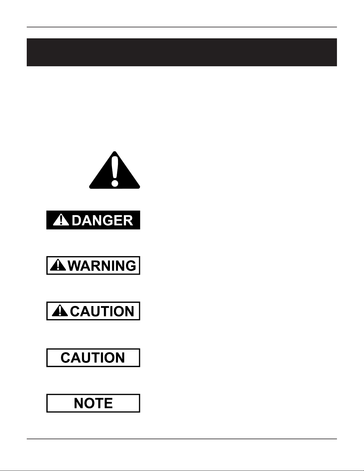
This is the safety alert symbol. It is used to alert you
to potential personal injury hazards. Obey all
safety messages that follow this symbol to avoid possible
injury or death.
DANGER indicates an imminently hazardous situation
which, if not avoided, will result in death or serious injury.
WARNING indicates a potentially hazardous situation which,
if not avoided, could result in death or serious injury.
CAUTION indicates a potentially hazardous situation which, if
not avoided, may result in minor or moderate injury.
CAUTION used without the safety alert symbol indicates a
potentially hazardous situation which, if not avoided, may
result in property damage.
NOTE indicates information about the equipment that you
should pay special attention to.
PNEG-739 42" - 48" Platforms & Safety Cages6
Page 7
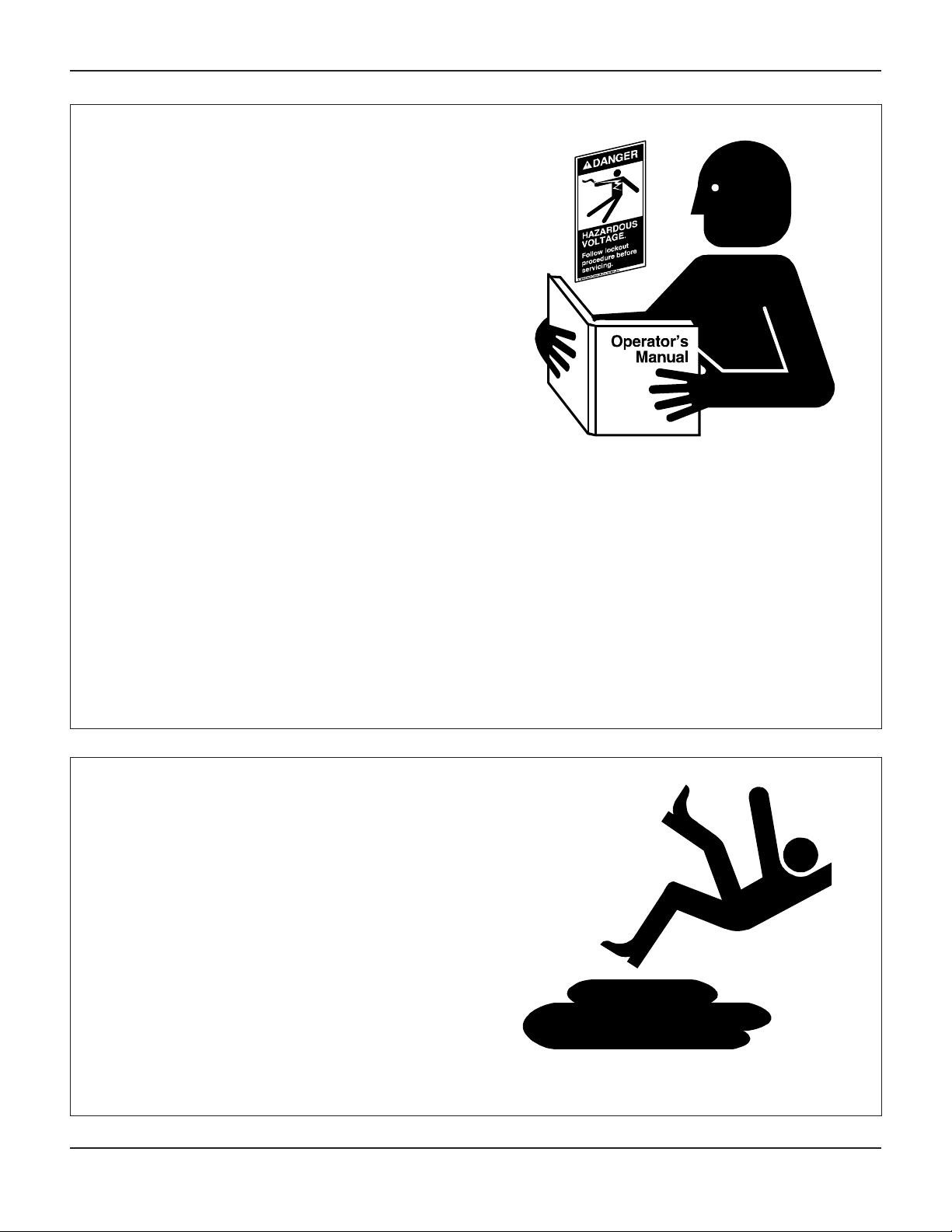
FOLLOW SAFETY INSTRUCTIONS
Carefully read all safety messages in this manual
and on your machine safety signs. Keep signs in
good condition. Replace missing or damaged
safety signs. Be sure new equipment components and repair parts include the current safety
signs. Replacement safety signs are available
from the manufacturer.
Learn how to operate the machine and how to
use controls properly. Do not let anyone operate
without instruction.
Keep your machinery in proper working condition. Unauthorized modifications to the machine
may impair the function and/or safety and affect
machine life. All service accessories are intended for the proper use in which they were
designed. Any misuse of the equipment or
accessories will void the warranty. Misuse can
cause failure, severe injury or death to the user.
The manufacturer cannot be responsible for the
erection or use of the bucket elevator and it’s
accessories.
Safety
If you do not understand any part of this manual
and need assistance, contact your dealer.
PRACTICE SAFE MAINTENANCE
Understand service procedures before doing
work. Keep area clean and dry.
Never lubricate, service, or adjust machine while
it is in operation. Keep hands, feet, and clothing
from rotating belt and idlers.
Keep all parts in good condition and properly
installed. Fix damage immediately. Replace
worn or broken parts. Remove any build up
grease, oil, or debris.
PNEG-739 42" - 48" Platforms & Safety Cages
7
Page 8
Safety
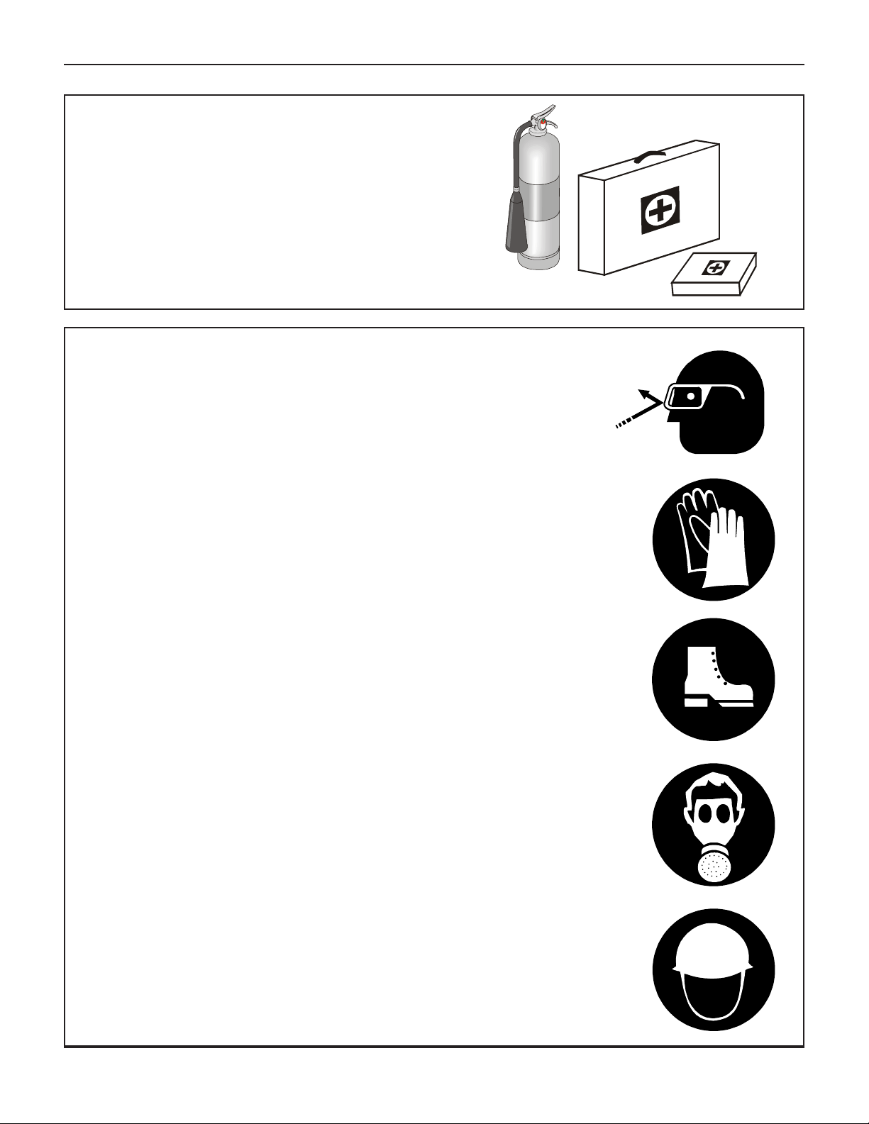
PREPARE FOR EMERGENCIES
Be prepared if fire starts.
Keep a first aid kit and fire extinguisher handy.
Keep emergency numbers for doctors, ambu-
lance service, hospital, and fire department near
your telephone.
WEAR PROTECTIVE CLOTHING
Wear close fitting clothing and safety equipment
appropriate to the job.
Safety glasses should be worn at all times to
protect eyes from debris.
Wear gloves to protect your hands from sharp
edges on plastic or steel parts.
A respirator may be needed to help prevent
breathing potentially toxic fumes and dust.
Wear hard hat and steel toe boots to help
protect your head and toes from falling debris.
Eye Protection
Gloves
Steel Toe Boots
Respirator
Hard Hat
PNEG-739 42" - 48" Platforms & Safety Cages8
Page 9
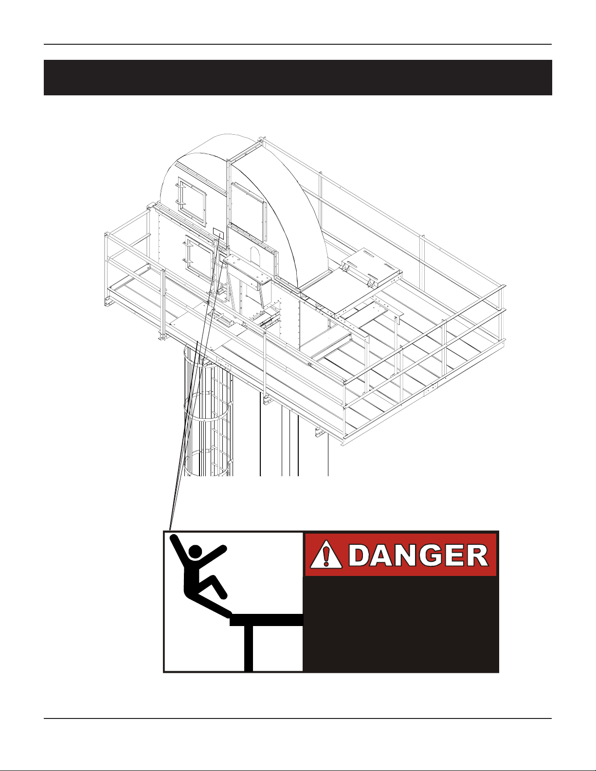
DECAL LOCATIONS
Decals
Decal located on bottom of platform access door and on
the side of the Head Assembly.
DC-1568
PNEG-739 42" - 48" Platforms & Safety Cages
FALL HAZARD
Serious injury or death will result.
Keep access door closed
while on platform.
DC-1568
9
Page 10
1
42'' Head Service Platform
SECTION 1
42" HEAD SERVICE PLATFORM
PNEG-739 42" - 48" Platforms & Safety Cages10
Page 11
42'' Head Service Platform
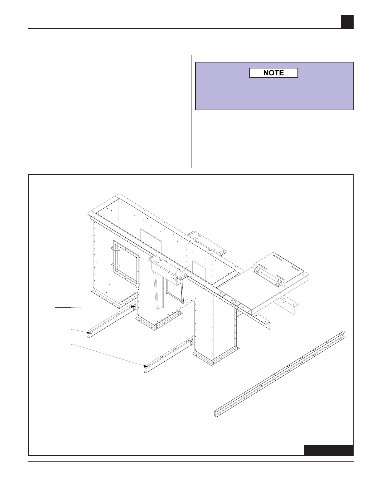
Suppor t Channels
Take time now and review all instructions and
drawings before attempting to assemble the platform. Layout all parts for easy identification.
Determine if the shaft will extend to the left or
right hand side of the platform. The long side of
the support channels must extend to the shaft
side of the head. Start the head service platform
assembly by attaching two support channels to
the head platform brackets using 1/2" x 1" hex
bolts. (See Figure 1-1.)
1
For entire platform assembly, use carriage bolts
at slot-to-hole connections and hex head cap
screws at hole-to-hole connections.
HSP42010
(Installed)
Left Hand Deck
Channel Support
Bracket
HSP42032 (2)
Platform Support
Channel 120"
HSP42012 (1)
Platform Support
Channel
FIGURE 1-1
FIGURE 1-1
PNEG-739 42" - 48" Platforms & Safety Cages
11
Page 12
1
Inside Toeboards
Place the side toeboards next to the head assembly on top of the support channels as shown
in Figure 1-2. The end platform support channel
must be placed below the two side toeboards.
Attach the toeboards to the support channels with
the 5/16" x 1" hex bolts supplied. Tighten all hardware in this assembly.
42'' Head Service Platform
Support
Channels
Toeboard Channel - 98.068"
End Platform Support Channel - 32"
FIGURE 1-2
FIGURE 1-2
PNEG-739 42" - 48" Platforms & Safety Cages12
Page 13
42'' Head Service Platform
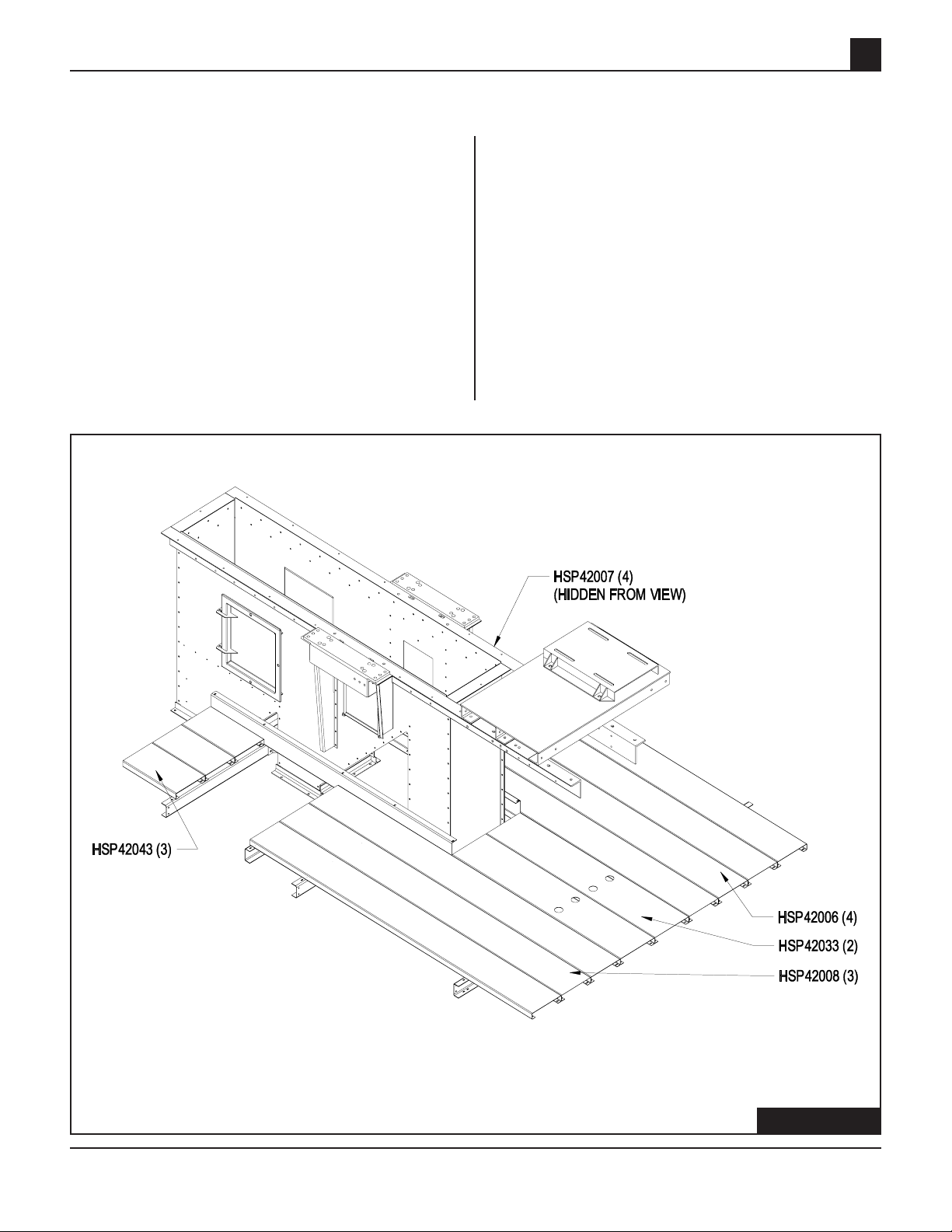
42" Platform Decking
Layout all floor deck panels according to position
on platform (Figure 1-3). Remember to layout
for right hand (standard) or left hand shaft. Attach
floor panels to support channels (as shown in
Figure 1-3) using 5/16" x 1" carraige bolts and
5/16" nuts.
1
Platform
Decking - 21.65"
Platform Decking - 73.625"
Platform Decking - 93"
Platform Decking - 68.607"
Platform Decking - 114.812"
FIGURE 1-3
NOTE: This layout is for a RIGHT hand drive setup.
PNEG-739 42" - 48" Platforms & Safety Cages
FIGURE 1-3
13
Page 14
1
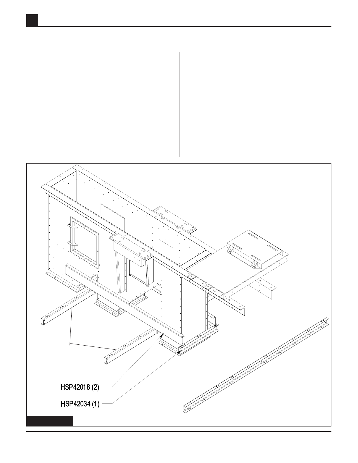
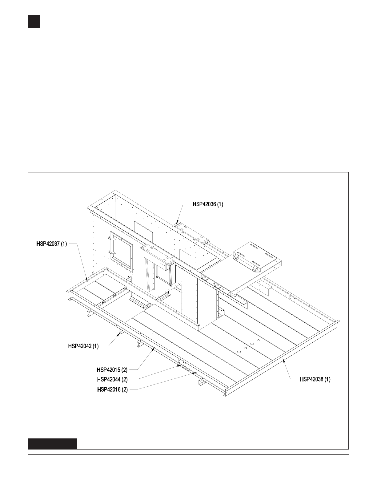
Outside Toeboards
Attach support channel, HSP42042, to underside
of floor panels at the hatch opening (Figure 1-4).
Small floor panels may be left off until the outside
toeboards are attached. Use the 5/16" x 1" hex
bolts during this assembly. Attach toeboards to
the ends of the deck panels and to the support
channels as shown in (Figure 1-4). Be sure and
use splice channel on side toe boards. Tighten
all hardware.
42'' Head Service Platform
Z Toeboard - 54"
Platform Support
Channel - 40"
Toeboard Channel - 120"
Toeboard Splice Plate
Toeboard Channel 46.976"
Z Toeboard - 42"
Z Toeboard 120"
FIGURE 1-4
FIGURE 1-4
PNEG-739 42" - 48" Platforms & Safety Cages14
Page 15
42'' Head Service Platform
41-3/4" & 47-3/4"
Handrail Posts
Attach short handrail posts to toeboards using
the 5/16" hardware as shown in Figure 1-5. There
are different lengths of handrail posts, so be sure
and use the (6) 41- ¾" lengths on the outside
and the 47-3/4" lengths next to the head as noted
in Figure 1-5.
1
Handrail Upright
Angle - 47.75"
Handrail
Upright Angle -
41.813"
FIGURE 1-5
PNEG-739 42" - 48" Platforms & Safety Cages
FIGURE1-5
15
Page 16
1
47-3/8" Handrail Posts
Attach long handrail posts to the support channels using 5/16" x 1" hex bolts as shown in Figure 1-6. Be sure and use the longer 47-3/8" handrail posts for this assembly.
42'' Head Service Platform
Handrail Upright
Angle - 47.402"
FIGURE 1-6
FIGURE 1-6
PNEG-739 42" - 48" Platforms & Safety Cages16
Page 17

42'' Head Service Platform
Handrail & Vertical
Suppor t Ang les
Attach platform hatch latch assembly, GSB30120,
to handrail as shown, using 5/16" x 1" hex bolts.
Locate all handrail angles and attach to the handrail posts, as shown in Figure 1-7, using the
5/16" hardware. Attach the two deck channel support angles, HSP42014, to the rear of the head
angles and to the support channel through the
holes provided in the center decking uisng 3/8" x
1" hex bolts.
Handrail Angle - 38.63"
1
Handrail Angle -
50.625"
Latch
Assembly
Latch
Assembly
Handrail Angle - 167.289"
Deck Channel
Support Angle
Handrail
Angle - 120"
FIGURE 1-7 FIGURE 1-7
PNEG-739 42" - 48" Platforms & Safety Cages
17
Page 18

1
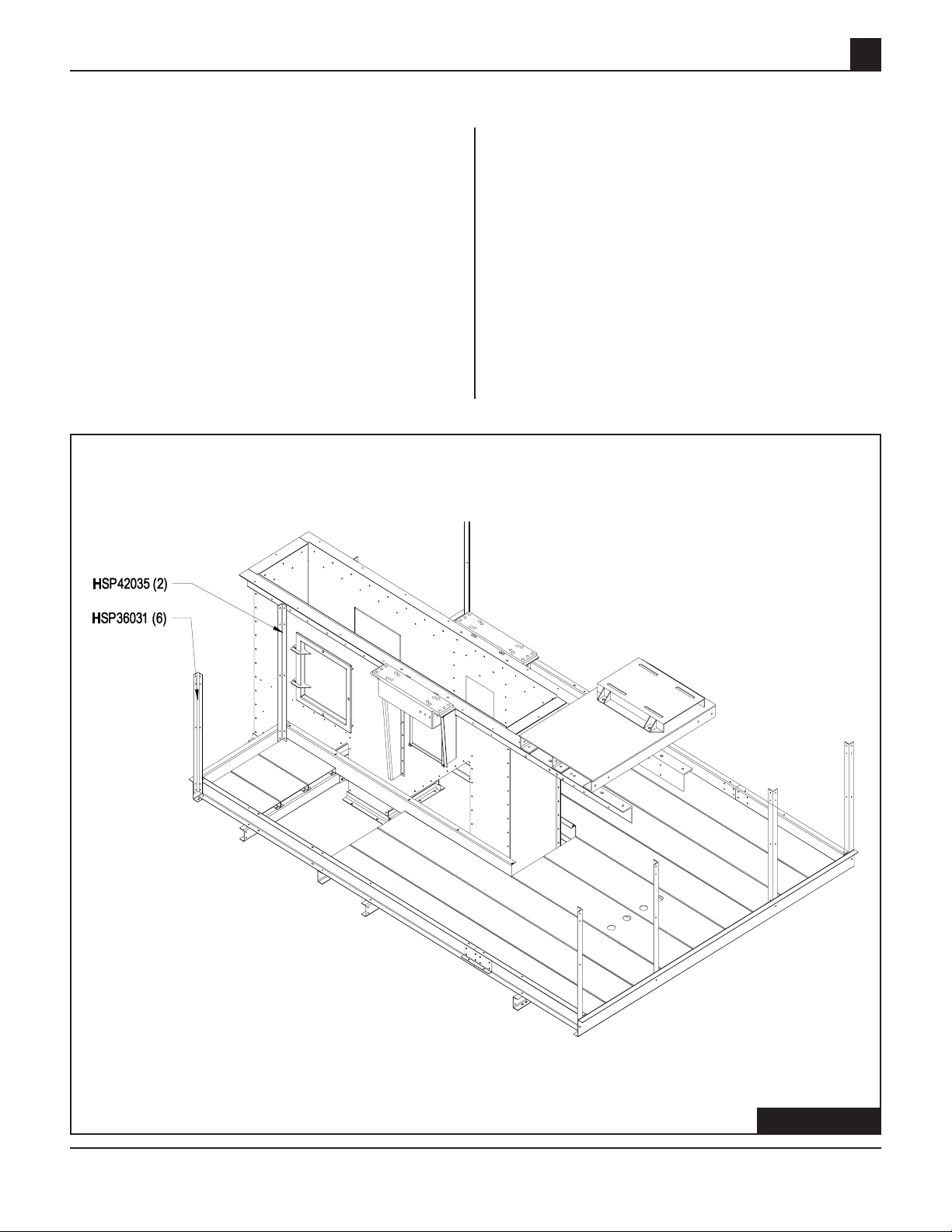
Handrail Retaining Clip
Attach the two HSP36027 handrail support clips
to the handrail uprights next to the head bearing
angle on the discharge end of head as shown in
Figure 1-8. Field drill the hole in each head bearing angle and attach using the 5/16" x 1" hex bolts
supplied.
Head Bearing Angle
42'' Head Service Platform
FIGURE 1-8
Handrail Retaining Clip
HSP42035
Handrail Upright Angle
FIGURE 1-8
PNEG-739 42" - 48" Platforms & Safety Cages18
Page 19

42'' Head Service Platform
Hatch Access Door
Assemble the deck hatch access door by attaching the left and right hand hinges to bottom side
of the outside toeboard, using 5/16" x 1" carraige
bolts. Leave hardware loose until the assembly
is complete. Attach the hinges & hatch decking
to the angle frame weldment and double nut the
hinge bolts - do not overtighten. (See Figure 1-9)
1
Right Hand
Hatch Hinge
Left Hand
Hatch Hinge
Decking Hatch
Frame Weldment
GSB36222 (1)
Hatch Service
Hatch Decking
FIGURE 1-9
PNEG-739 42" - 48" Platforms & Safety Cages
FIGURE 1-9
19
Page 20

2
48'' Head Service Platform
SECTION 2
48" HEAD SERVICE PLATFORM
PNEG-739 42" - 48" Platforms & Safety Cages20
Page 21

48'' Head Service Platform
Mainframe & Cr oss Member Assembl y
2
Before attempting any assembly of the platform,
read and follow all directions. Lay out all parts
associated with the assembly. Due to the
assembly of the head service platform, the lower
head assembly may need to be blocked up under
the head and discharge flanges approximately
12" to provide clearance for assembly. Look at
the head assembly to determine the drive side,
which will be the wide side of platform.
First, attach the left and right mainframe
assemblies to the head using 1/2" x 1" hex bolts.
Then attach the cross members to the mainframe
assemblies with the long end of channels
extending towards the drive side, use the ½" x 1"
hex bolts supplied. (See Figure 2-1)
The middle cross member HSP48x106 has a
double hole pattern. Be sure to orientate the
cross members according to Figure 2-1. Right
Drive platform layout shown in all figures.
When items with more than one part# are shown you
will only use the one relevant to your service platform.
Example: HSP482xxx single row 48" elevator,
HSP484xxx double row 38"- 42" wide 48" elevator,
HSP485xxx double row 50" wide 48" elevator.
HSP482106 (1) - Cross Member Assembly Double Hole - 26"
HSP484106 (1) - Cross Member Assembly Double Hole - 38"-42"
HSP485106 (1) - Cross Member Assembly Double Hole - 50"
FIGURE 2-1
PNEG-739 42" - 48" Platforms & Safety Cages
HSP48401 (1) - Right
Mainframe Assembly
HSP48402 (1) - Left
Mainframe Assembly
HSP482105 (1) - Cross Member Assembly - 26"
HSP484105 (1) - Cross Member Assembly - 38"-42"
HSP485105 (1) - Cross Member Assembly - 50"
FIGURE 2-1
21
Page 22

2
Toe Plates
48'' Head Service Platform
Now that cross members are attached to head
assembly, the toe board channel assemblies
(HSP484117) can be attached to the ends of the
cross members using 1/2" x 1" hex bolts. After
both toe board channels are in place the Z-board
channels (HSP48x121) can be placed on the end
of the toe board channels and bolted in place
using 3/8" x 1" hex bolts. Now tighten all hardware. Attach the (8) toe guard mounting angles
(HSP484024) to the cross members then attach
the inner toe boards to the angles using 1/2" x 1"
NOTE: Some parts may have been
eliminated for clarity of assembly.
Toe Plate, Platform
End (38-42)
hex bolts. The inboard mounting for toe board
HSP484036 – HSP484037 will be done when the
hand rail post are assembled. (See Figure 2-2)
The lower head assembly has been
removed from figure below to help clarify
the assembly process.
HSP484029 (1) Toe Plate, Inner
Down Leg (38"-42")
HSP484117 (2) Toeboard Channel
Assembly (38"-42"-50")
Toe Guard Mounting
Angle (38-42)
HSP484037 (1)
Toe Plate Platform
End (38-42)
Toe Plate, Inner
Down Leg
Toe Plate, Inner
Upleg (38-42)
8
HSP482028 (1) Toe Plate Inner Upleg-26"
HSP484028 (1) Toe Plate Inner Upleg-38"-42"
HSP485028 (1) Toe Plate Inner Upleg-50"
HSP484026 (1) Toe Plate,
Inner Upleg (38"-42")
HSP482121 (1) Z-Board Channel Assembly - 26"
HSP484121 (1) Z-Board Channel Assembly - 38"-42"
HSP485121 (1) Z-Board Channel Assembly - 50"
FIGURE 2-2
FIGURE 2-2
PNEG-739 42" - 48" Platforms & Safety Cages22
Page 23

48'' Head Service Platform
Decking
With all support channels in place and hardware
tightened, locate all floor deck panels. Position
the floor deck panels onto the support channels
as shown below. Use the 5/16" x 1" carriage
bolts to attach ends of the deck panels to the
support channels. (See Figure 2-3)
NOTE: Some parts may have been
eliminated for clarity of assembly.
2
The quantity of HSP484013 will be
determined by the width of the service platform.
SP-4826 = 1, SP-483842 = 2, SP-4850 = 3.
Platform Decking -
48.625"
Platform Decking - 123"
FIGURE 1-12
Platform
Decking - 86"
Platform
Decking - 122"
Platform Decking -
69.313"
Platform Decking -
69.313"
NOTE: HSP48013 can have up to 5
planks depending on the size of platform.
FIGURE 2-3
PNEG-739 42" - 48" Platforms & Safety Cages
23
Page 24

2
Handrails and Handr ail
Posts
Bolt all handrail posts to the cross members and
Z board channels. Post that attach to cross members will use 1/2" hardware, post that attach to
the Z board will use 3/8" hardware. Leave all
hardware loose until all posts and handrails are
in place. With all post in place attach hand rails
with 3/8" hardware. Review Figure 2-4 for proper
placement of post and handrails. HSP 484040
posts are attached to Z-board channel only.
HSP484045 (2) 60.250"
Handrail (38"-50")
48'' Head Service Platform
HSP484042 (2) 49.000"
Discharge Post (38"-50")
HSP484046 (2) 30"
Handrail (38"-50")
HSP484041 (6) Handrail Angle (38"-50")
HSP484044 (4) Side Handrail (38"-50")
HSP484040 (4) 42"
Angle Post (38"-50")
FIGURE 2-4
HSP482043 (2) End Handrail (26")
HSP484043 (2) End Handrail (38"-42")
HSP485043 (2) End Handrail (50")
FIGURE 5-1
PNEG-739 42" - 48" Platforms & Safety Cages24
Page 25

48'' Head Service Platform
Handrail Ang les
Attach HSP484047 and HSP484048 handrail attachment angles to the post next to the head
bearing angle on the discharge end of the lower
head (Figure 2-5) Field drill the hole in each head
bearing angle and use 3/8" x 1" hex bolts supplied.
Attach the two service platform support angles,
HSP484038, to rear of head angles and to the
support channel through the holes provided in
the center decking using 3/8" x 1" hex bolts. (See
Figure 2-5)
HSP484048 Right Attachment Angle for Handrail
2
HSP484047 Left Attachment Angle for Handrail
Service Platform
Support Angle
PNEG-739 42" - 48" Platforms & Safety Cages
FIGURE 2-5
25
Page 26

2
48'' Head Service Platform
Hatch Access Door
Assemble the deck hatch access door by
attaching the left and right hand hinges to bottom
side of the outside toeboard (HSP484117) using
5/16" x 1" hex bolts. Leave hardware loose until
the assembly is complete. Attach hatch assembly
(HSP484055) to the hinges and double nut the
hinge bolts. Do not over tighten.
NOTE: Only applicable for 38" - 72"
wide bucket elevators.
Two Rung Ladder
Attach the ladder standoff angles as shown
below using 1/2" x 1" hex bolts. Then attach two
rung ladder to the standoff angles using
1/2" x 1" hex bolts. The top rung of the ladder
should be even with the top of the decking when
installed.Tighten all hardware. (See Figure 2-6)
HSP484117 Toeboard
Channel Assembly (38"-50")
HSP36003 Left Hand
Hatch Hinge
HSP36002 Right
Hand Hatch Hinge
HSP484055 Platform Hatch
HSP484051 Two Rung Ladder
(See Note.)
BE-PLAT1 (2) Ladder
Standoff Angle
(See Note.)
BE-PLAT2 (2) Ladder
Standoff Angle
(See Note.)
FIGURE 2-6
PNEG-739 42" - 48" Platforms & Safety Cages26
Page 27

48'' Head Service Platform
Grab Bar Installation
Attach the grab bar attachment angles
(HSP484035) to the grab bar mounting angle
using 3/8" x 1" hex bolts. Then fasten the grab
bar weldment to the attachment angles and the
head bearing angle using 3/8" x 1" hex bolts.
Recheck assembly to be sure all hardware is
secure.
NOTE: Only applicable for 38" - 72"
wide bucket elevators.
2
Head Bearing Angle
HSP484033 Grab
Bar Weldment
HSP484034 Grab
Bar Mounting Angle
HSP484035 Grab
Bar Attachment Angle
GSB30120 Latch
Assembly
PNEG-739 42" - 48" Platforms & Safety Cages
FIGURE 2-7
27
Page 28

3
Distributor Platform Assembly
SECTION 3
DISTRIBUTOR PLATFORM
PNEG-739 42" - 48" Platforms & Safety Cages28
Page 29

Distributor Platform Assembly
Clamp Brackets
3
This assembly is designed to be located at any
elevation on trunking that’s needed to provide access to other equipment. Determine elevation of
platform surface and work from there. Locate all
parts required for assembly by using the charts
shown in the following figures.
Locate all clamp halves, clamp brackets, threaded
rods, and hardware to assemble clamps onto the
trunking. Measure the distance between the
clamps to assure proper location for support channels and knee brace attachment. See clamp
detail in FIgure 3-1 for hardware orientation.
Place 5/8" nuts and lock washers on a threaded
rod (one from each end). Place a clamp half on
each end of the rod and thread another nut and
lock washer to hold clamp in place. Now place
that assembly around trunk and place a clamp
bracket onto the opposite end of the clamp assembly and use ½" hardware to fasten parts together. Adjust the position of the inside nuts of
the rod assembly to allow the clamps to be tightened onto the trunking.
TIGHTEN CLAMPS ONTO TRUNKING, DO NOT
OVERTIGHTEN AND COLLAPSE THE TRUNKING.
Position inside nuts back to the clamp and tighten.
42" SINGLE TRUNKING
DSP42007 (6) Platform Brace Clamp Half
DSP42008 (3) Brace Clamp Rod
DSP42006 (3) Clamp Half, 42" (22)
48" SINGLE TRUNKING
DSP42007 (6) Platform Brace Clamp Half
DSP48008 (3) Brace Clamp Rod
DSP48006 (3) Clamp Half, 48" (26)
FIGURE 3-1
PNEG-739 42" - 48" Platforms & Safety Cages
FIGURE 3-1
29
Page 30

3
Distributor Platform
Suppor t and Br ace
Channels
With clamps fastened securely to the trunk, attach
the platform support channels to the middle
clamp, use ½" hardware with this assembly. The
platform brace channels will attach in the upper
set of holes on side of support channel and to
the lower clamp. Before tightening hardware, the
support channels must be perpendicular to the
trunk, now tighten all hardware. (See Figure 3-2)
Distributor Platform Assembly
FIGURE 3-2
Platform Support Channel (2)
Platform Brace Channel (2)
FIGURE 3-2
PNEG-739 42" - 48" Platforms & Safety Cages30
Page 31

Distributor Platform Assembly
Distributor Platform
Toeboards
The toeboards will not be centered on trunking
but should be offset to the ladder side. Platform
is designed to work for either side of trunking
access.
With support assembly attached to trunk and
hardware tightened, proceed by attaching the
notched toe board and unnotched toeboard to
the top of the support channel using the 5/16"
hardware provided. (Leave hardware loose). See
Figure 3-3.
3
Notched Toeboard Angle
Toeboard Angle
FIGURE 3-3
PNEG-739 42" - 48" Platforms & Safety Cages
FIGURE 3-3
31
Page 32

3
Distributor Decking and
Toeboards
Attach the floor deck panels to the support channels using 5/16" x 1" hex bolts. Then attach decking to end toe boards with the 5/16" x 1" hex bolts
provided. After all pieces have been attached,
tighten all hardware. (See Figure 3-4)
Distributor Platform Assembly
Toeboard Angle (2)
Platform Decking (6)
FIGURE 3-4
FIGURE 3-4
PNEG-739 42" - 48" Platforms & Safety Cages32
Page 33

Distributor Platform Assembly
Handrail Posts and
Handrail Ang les
Locate the toe board cover plate and bolt over
the unused notched toe board area 5/16" x 1"
hex bolts. Attach handrail posts to the toe
boards as shown using the 5/16" x 1" hex bolts
provided. (Leave hardware loose until all
handrails are in place.) Attach all handrail
angles and brace angle 5/16" x 1" hex bolts.
(See Figure 3-5.) After all pieces have been
attached go back and tighten all hardware.
3
Handrail Clip
Bracket
Toeboard Plate
Handrail Brace
Handrail Angles
Handrail Angles
Handrail Angles
FIGURE 3-5
PNEG-739 42" - 48" Platforms & Safety Cages
Handrail Upright
Angle (5)
FIGURE 3-5
33
Page 34

3
Cross Knee Br aces
Attach cross knee brace diagonals to bottom side
of the knee braces 1/2" x 1" hex bolts. This will
add extra stability to the distributor platform. (See
Figure 3-6.)
Distributor Platform Assembly
FIGURE 3-6
Cross Knee Brace
FIGURE 3-6
PNEG-739 42" - 48" Platforms & Safety Cages34
Page 35

Safety Cage Assembly
SAFETY CAGE ASSEMBLY
4
SECTION 4
PNEG-739 42" - 48" Platforms & Safety Cages
35
Page 36

4
Tie Angle Attachment
Attach the up and down legs together with the tie
angles. Position the tie angles around the trunking
joint as shown. Fasten the tie angles to the
trunking angles using 1/2"-13 x 1" bolts. (See Fig.
4-1)
Safety Cage Assembly
1/2"-13 x 1" Hex Bolt
Trunking Section
1/2" -13 Hex Nut
Trunking
Angles
FIGURE 4-1
Tie Angle
PNEG-739 42" - 48" Platforms & Safety Cages36
Page 37

Safety Cage Assembly
4
Tie Angle Dimensions
See Figure 4-2B for 42" & 48" tie angle dimensions. Only the 42" and 48" elevators have tie
angle cross braces that brace the two tie angles
diagonally. (One per pair of tie angles.) (See Figure 4-2A)
BECT4204 42" Tie Angle
Tie Angle Cross Braces
FIGURE 4-2A
.000
2.000
.000
1.000
8.500
10.000
16.500
23.500
29.000
Ø .563
(8 PL.)
49.000
54.500
61.500
69.500
68.000
77.000
78.000
BECT4833 48" Tie Angle
PNEG-739 42" - 48" Platforms & Safety Cages
FIGURE 4-2B
37
Page 38

4
Ladder Standoff
Attachment
Attach the ladder standoff brackets to the tie
angles using 1/2" x 1" hex bolts as shown in Figure 4-3.
Safety Cage Assembly
1/2"-13
Hex Nut
Ladder Standoff
Bracket
Left - (BE-PLAT1)
1/2"-13 x 1" Hex Bolt
Ladder Standoff
Bracket
Right - (BE-PALT2)
FIGURE 4-3
PNEG-739 42" - 48" Platforms & Safety Cages38
Page 39

Safety Cage Assembly
Ladder Attachment
Attach the ladder to the standoffs using 1/2"-13 x
1" hex bolts. When attaching the ladder to the
standoffs, the ladder is attached through the second hole down the front end of the ladder. The
first hole is for the safety cage hoop. Attach the
safety hoop to the ladder using 1/2" x 1"hex bolts.
(See Figure 4-4)
4
27" Safety Cage
Hoop (27Hoop)
**NOTE: A ten foot section is used at
anytime the ladder continues on to
another section of ladder. A fourteen
foot section is used anytime the ladder
extends through any platform deck.
1/2"-13 x 1"
Hex Bolt
1/2"-13 Hex Nut
PNEG-739 42" - 48" Platforms & Safety Cages
10' Ladder
Section** (10foot)
FIGURE 4-4
39
Page 40

4
Safety Cage Hoop
Assembly
Bolt all safety cage hoops to ladder as shown
below using 1/2" x 1" hex bolts. Leave all bolts
loose until the vertical bars are in place and then
tighten all hardare. (See Figure 4-5)
Safety Cage Assembly
FIGURE 4-5
PNEG-739 42" - 48" Platforms & Safety Cages40
Page 41

Safety Cage Assembly
Safety Cage Vertical Bar
Attachment
Bolt all safety cage vertical bars to the cage hoops
shown below. The vertical bars should be installed
to the inside of the hoops using 1/2" x 1" hex
bolts. (See Figure 4-6)
4
PNEG-739 42" - 48" Platforms & Safety Cages
1/2-13 x 1" Hex Bolt
1/2"-13 Hex Nut
Safety Cage Vertical
Bar (10Foot-V)
FIGURE 4-6
41
Page 42

4
Safety Cage Flar e
Attachment
Attach the safety cage tapper vertical bars to the
inside of the 27" & 30 " safety hoops using 1/2" x
1" hex bolts. (See Figure 4-6) Then fasten the
27" safety cage hoop through the top hole on the
ladder using 1/2" x 1" hex bolts. Install the 30"
Hoop to the ladder using 1/2" x 1" hex bolts.
Safety Cage Assembly
27" Safety Cage
Hoop (27hoop)
1/2"-13
Hex Nut
30" Safety
Cage Hoop
(30hoop)
1/2"-13 x 1" Hex Bolt
Safety Cage Tapper
Vertical Bar (taper-v)
FIGURE 4-6
PNEG-739 42" - 48" Platforms & Safety Cages42
Page 43

Rest Platf orm Assembly
REST PLATFORM ASSEMBLY
5
SECTION 5
PNEG-739 42" - 48" Platforms & Safety Cages
43
Page 44

5
Installing Side Mounting
Channels
The first step to assemble the rest platform is to
attach the side mounting channels to the tie
angles using 1/2" x 1" hex bolts. (See Figure 5-1)
Rest Platf orm Assembly
LEFT SIDE
MOUNTING CHANNEL
RSP48203 - 26"
RSP484003 - 30" & 42"
RSP485003 - 50"
RSP486003 - 60"
FIGURE 5-1
1/2"-13 Hex Nut
1/2"-13 x 1" Hex Bolt
RIGHT SIDE
MOUNTING CHANNEL
RSP48202 - 26"
RSP484002 - 30" & 42"
RSP485002 - 50"
RSP486002 - 60"
FIGURE 5-1
PNEG-739 42" - 48" Platforms & Safety Cages44
Page 45

Rest Platf orm Assembly
Platform Corner Post
Next attach the platform corner posts to the
mounting channels as shown below using 1/2" x
1" hex bolts. Leaving hardware loose will help fit
other parts in place. (See Figure 5-2)
5
FIGURE 5-2
RSP48007 Platform
Corner Post - 42" & 48"
1/2"-13 Hex Nut
1/2"-13 x 1" Hex Bolt
FIGURE 5-2
PNEG-739 42" - 48" Platforms & Safety Cages
45
Page 46

5
Front and Rear Mounting
Channels
The next step is to attach the front and rear
support channel to the platform corner posts as
shown below using 1/2" x 1" hex bolts. (See
Figure 5-3)
Rest Platf orm Assembly
1/2"-13 Hex Nut
1/2"-13 x 1" Hex Bolt
RSP48005 Front Support Channel - 42" & 48"
RSP48206 Rear Mounting Channel - 42" & 48"
FIGURE 5-3
FIGURE 5-3
PNEG-739 42" - 48" Platforms & Safety Cages46
Page 47

Rest Platf orm Assembly
Center Suppor t Channel
To complete the support frame, bolt on the center
support channel to the front and rear support
channel using 1/2" x 1" hex bolts. (See Figure 5-4)
5
1/2"-13 Hex Nut
1/2"-13 x 1" Hex Bolt
RSP48204 Center Support Channel - 42" & 48"
FIGURE 5-4
PNEG-739 42" - 48" Platforms & Safety Cages
FIGURE 5-4
47
Page 48

5
Rest Platfor m Deck Plate
Using the 1/4" hardware, bolt the deck tread plate
to the mounting and support frames. (See Figure
5-5)
Rest Platf orm Assembly
FIGURE 5-5
1/4"-20 x 1" Hex Bolt
1/4"-13 Hex Nut
1/4" Flat Washer
RSP48201 Rest Platform
Deck Tread Plate - 42" & 48"
FIGURE 5-5
PNEG-739 42" - 48" Platforms & Safety Cages48
Page 49

Rest Platf orm Assembly
Top and Mid Handr ails
Bolt on all the top and mid handrails following
picture below using 1/2" x 1" hex bolts. (See
Figure 5-6)
5
1/2"-13 x 1" Hex Bolt
1/2"-13 Hex Nut
RPS48209
Top & Mid Hand Rail (Left
and Right) - 42" & 48"
RPS48008
Top & Mid Hand Rail (Front
and Rear) - 42" & 48"
FIGURE 5-6
PNEG-739 42" - 48" Platforms & Safety Cages
FIGURE 5-6
49
Page 50

5
Kickplates
To complete the rest platform, bolt on all
toeboards to the platform corner posts as shown
using the hardware in figure 5-7. Recheck all
hardware in assembly to ensure proper tightness.
Rest Platf orm Assembly
RSP48012
Kick Plate (Left & Right) - 42" & 48"
1/2"-13 x 1" Hex Bolt
1/2"-13 Hex Nut
RSP48210
Front Kick Plate - 42" & 48"
RSP48211
Rear Kick Plate - 42" & 48"
FIGURE 5-7
1/4"-20 x 1" Hex Bolt
1/4"-20 Hex Nut
FIGURE 5-7
PNEG-739 42" - 48" Platforms & Safety Cages50
Page 51

The GSI Group, Inc. Warranty
THE GSI GROUP, INC. (“GSI”) WARRANTS ALL PRODUCTS WHICH IT MANUFACTURES TO
BE FREE OF DEFECTS IN MATERIAL AND WORKMANSHIP UNDER NORMAL USAGE AND
CONDITIONS FOR A PERIOD OF 12 MONTHS AFTER RETAIL SALE TO THE ORIGINAL END
USER. THE PURCHASER’S SOLE REMEDY AND GSI’S ONLY OBLIGATION SHALL BE TO
REPAIR OR REPLACE, AT GSI’S OPTION AND EXPENSE, PRODUCTS THAT, IN GSI’S SOLE
JUDGMENT, CONTAIN A MATERIAL DEFECT DUE TO MATERIALS OR WORKMANSHIP.
ALL DELIVERY AND SHIPMENT CHARGES TO AND FROM GSI’S FACTORY WILL BE
PURCHASER’S RESPONSIBILITY. EXPENSES INCURRED BY OR ON BEHALF OF THE
PURCHASER WITHOUT PRIOR WRITTEN AUTHORIZATION FROM AN AUTHORIZED
EMPLOYEE OF GSI SHALL BE THE SOLE RESPONSIBILITY OF THE PURCHASER.
EXCEPT FOR THE LIMITED WARRANTY EXPRESSED ABOVE, GSI MAKES NO FURTHER
WARRANTY OF ANY KIND, EXPRESS OR IMPLIED, INCLUDING, WITHOUT LIMITATION,
WARRANTIES OF MERCHANTABILITY OR FITNESS FOR A PARTICULAR PURPOSE OR USE
IN CONNECTION WITH (I) PRODUCT MANUFACTURED OR SOLD BY GSI OR (ii) ANY
ADVICE, INSTRUCTION, RECOMMENDATION OR SUGGESTION PROVIDED BY AN AGENT,
REPRESENTATIVE OR EMPLOYEE OF GSI REGARDING OR RELATED TO THE
CONFIGURATION, INSTALLATION, LAYOUT, SUITABILITY FOR A PARTICULAR PURPOSE,
OR DESIGN OF SUCH PRODUCTS.
GSI SHALL NOT BE LIABLE FOR ANY DIRECT, INDIRECT, INCIDENTAL OR
CONSEQUENTIAL DAMAGES, INCLUDING, WITHOUT LIMITATION, LOSS OF ANTICIPATED
PROFITS OR BENEFITS. PURCHASER’S SOLE AND EXCLUSIVE REMEDY IS AS SET FORTH
IN THE LIMITED WARRANTY EXPRESSED ABOVE, WHICH SHALL NOT EXCEED THE
AMOUNT PAID FOR THE PRODUCT PURCHASED. THIS WARRANTY IS NOT
TRANSFERABLE AND APPLIES ONLY TO THE ORIGINAL PURCHASER. GSI SHALL HAVE
NO OBLIGATION OR RESPONSIBILITY FOR ANY REPRESENTATIONS OR WARRANTIES
MADE BY OR ON BEHALF OF ANY DEALER, AGENT OR DISTRIBUTOR OF GSI.
GSI ASSUMES NO RESPONSIBILITY FOR CLAIMS RESULTING FROM ERECTION DEFECTS
OR UNAUTHORIZED MODIFICATIONS TO PRODUCTS WHICH IT MANUFACTURED.
MODIFICATIONS TO PRODUCTS NOT SPECIFICALLY DELINEATED IN THE MANUAL
ACCOMPANYING THE EQUIPMENT AT INITIAL SALE WILL NULLIFY THE PRODUCT
WARRANTY THAT MIGHT HAVE BEEN OTHERWISE AVAILABLE.
THE FOREGOING WARRANTY SHALL NOT EXTEND TO PRODUCTS OR PARTS WHICH
HAVE BEEN DAMAGED BY NEGLIGENT USE, MISUSE, ALTERATION OR ACCIDENT. THIS
WARRANTY EXTENDS SOLELY TO ONLY PRODUCTS MANUFACTURED BY GSI. THIS
WARRANTY IS EXCLUSIVE AND IN LIEU OF ALL OTHER WARRANTIES EXPRESS OR
IMPLIED. GSI RESERVES THE RIGHT TO MAKE DESIGN OR SPECIFICATION CHANGES AT
ANY TIME.
PRIOR TO INSTALLATION, PURCHASER HAS THE RESPONSIBILITY TO COMPLY WITH ALL
FEDERAL, STATE AND LOCAL CODES WHICH MAY APPLY TO THE LOCATION AND
INSTALLATION OF PRODUCTS MANUFACTURED OR SOLD BY GSI.
PHLEGAL: #1832020 v1 (139LG01!.DOC) (revised December 2005)
Page 52

This Equipment shall be installed in accordance
with the current installation codes and applicable
regulations which should be carefully followed in
all cases. Authorities having jurisdiction should be
consulted before installation occurs.
Copyright © 2005 by The GSI Group
Printed in the USA
1004 East Illinois Street
Assumption, IL 62510
217-226-4421 Phone
800-800-5329 FAX
 Loading...