

Page 1
Autoflow Operation
Autoflow Operation
PNEG-728
1
1
Page 2

This page was left blank intentionally.
Autoflow Operation
2
Page 3

Autoflow Operation
Roof Damage Warning and Disclaimer.............................................................................4
Safety.............................................................................................................................5
Safety Precautions........................................................................................................6
Safety Sign-Off Sheet...................................................................................................7
Electrical Power Supply................................................................................................8
Electronic Monitoring Control System..............................................................................9
Dryer Control Panel..............................................................................................10
Set-Up Standard...................................................................................................14
Set-Up Extended...................................................................................................15
Fill System Control Box..............................................................................................18
Error Messages.............................................................................................................20
Pre-Season Checks......................................................................................................24
Top Dry Autoflow Theory of Operation.....................................................................27
Start Up Procedure......................................................................................................29
TopDry Autoflow Drying Rates for Shelled Corn......................................................32
TopDry Batch Drying Rates for Shelled Corn............................................................33
Warranty.....................................................................................................................34
TABLE OF CONTENTS
3
Page 4

SAFETY
Autoflow Operation
Roof Damage Warning and Disclaimer
GSI DOES NOT WARRANT ANY ROOF DAMAGE
CAUSED BY EXCESSIVE VACUUM OR INTER-
NAL PRESSURE FROM FANS OR OTHER AIR
MOVING SYSTEMS. ADEQUATE VENTILATION
AND/OR "MAKEUP AIR" DEVICES SHOULD BE
PROVIDED FOR ALL POWERED AIR HANDLING
SYSTEMS. GSI DOES NOT RECOMMEND THE
USE OF DOWNWARD FLOW SYSTEMS (SUC-
TION). SEVERE ROOF DAMAGE CAN RESULT
FROM ANY BLOCKAGE OF AIR PASSAGES.
RUNNING FANS DURING HIGH HUMIDITY/
COLD WEATHER CONDITIONS CAN CAUSE AIR
EXHAUST OR INTAKE PORTS TO FREEZE.
Fan/Heater Installation & Operating Instructions
Thank you for choosing a Top Dry Series Autoflow.
It is designed to give excellent performance and ser-
vice for many years.
This manual describes the installation for all
standard production Top Dry single fan, multi-fan
and Heater Control units. Different models are avail-
able for liquid propane or natural gas fuel supply,
with either single-phase 230 volt, or three-phase 208,
220, 380, 460 or 575 volt electrical power.
The principal concern of The GSI Group, Inc.
("GSI") is your safety and the safety of others asso-
The symbol shown is used to call your
attention to instructions concerning
your personal safety. Watch for this
symbol; it points out important safety
precautions. It means "ATTENTION",
"WARNING", "CAUTION", and
"DANGER". Read the message and
be cautious to the possibility of per-
sonal injury or death.
ciated with grain handling equipment. This manual
is written to help you understand safe operating pro-
cedures and some of the problems that may be en-
countered by the operator or other personnel.
As owner and/or operator, it is your responsi-
bility to know what requirements, hazards and pre-
cautions exist, and to inform all personnel associ-
ated with the equipment or who are in the fan area.
Avoid any alterations to the equipment. Such al-
terations may produce a very dangerous situation,
where serious injury or death may occur.
Safety Alert Symbol
WARNING! BE ALERT!
Personnel operating or working
around electric fans should read this
manual. This manual must be
delivered with the equipment to its
owner. Failure to read this manual
and its safety instructions is a
misuse of the equipment.
4
Page 5
Autoflow Operation
The GSI Group Inc. recom-
mends contacting your local
power company, and having a
representative survey your instal-
lation so the wiring is compatible
with their system, and adequate
power is supplied to your unit.
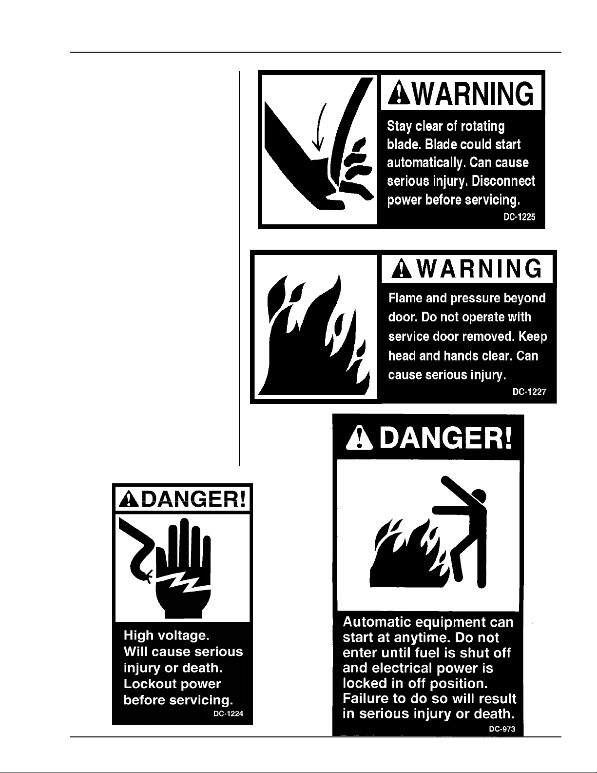
Safety decals should be read
and understood by all people in
the grain handling area. The ro-
tating blade, fire warning decals
and voltage danger decal must be
displayed on the fan can. The bot-
tom right decal should be present
on the inside bin door cover of
the two-ring door, 24" porthole
door cover and the roof manway
cover.
If a decal is damaged or is
missing,contact:
The GSI Group Inc.
1004 E. Illinois St.
Assumption, IL 62510
217-226-4421
A free replacement will be sent to
you.
SAFETY
5
Page 6
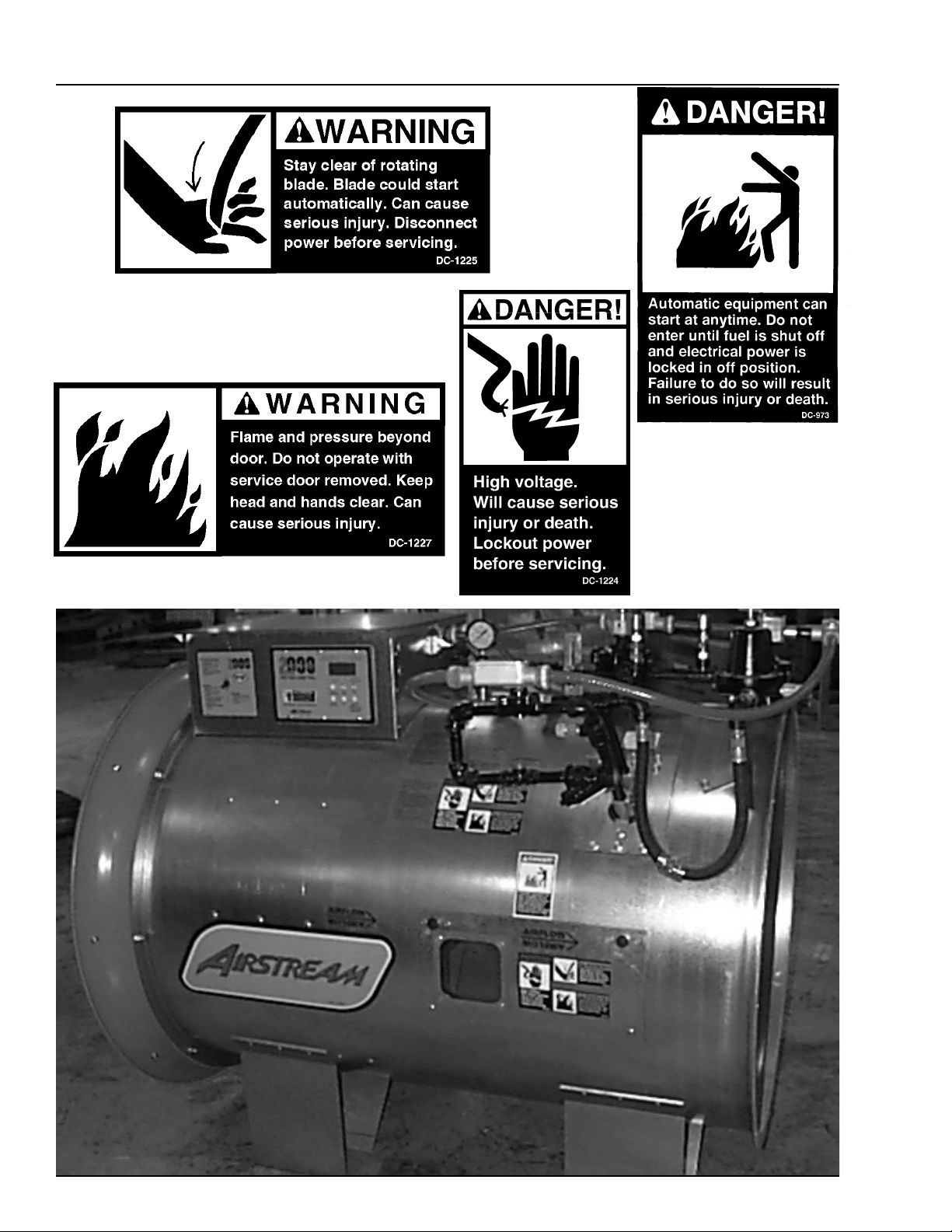
DECAL PLACEMENT
Autoflow Operation
6
Page 7

Autoflow Operation
SAFETY PRECAUTIONS
READ THESE INSTRUCTIONS
BEFORE OPERATION AND SERVICE
SAVE FOR FUTURE REFERENCE
1. Read and understand the operating manual before trying to operate the
dryer.
2. Power supply should be OFF for service of electrical components. Use
CAUTION in checking voltage or other procedures requiring power to
be ON.
3. Check for gas leaks at all gas pipe connections. If any leaks are de-
tected, do not operate the dryer. Shut down and repair before further
operation.
4. Never attempt to operate the dryer by jumping or otherwise bypassing
any safety devices on the unit.
5. Set pressure regulator to avoid excessive gas pressure applied to burner
during ignition and when burner is in operation. Do not exceed maxi-
mum recommended drying temperature.
6. Keep the dryer clean. Do not allow fine material to accumulate in the
plenum or drying chamber.
Use Caution in the
Operation of this
Equipment
The design and manufacture of this
dryer is directed toward operator
safety. However, the very nature of
a grain dryer having a gas burner,
high voltage electrical equipment
and high speed rotating parts, does
present a hazard to personnel which
cannot be completely safeguarded
against without interfering with ef-
ficient operation and reasonable ac-
cess to components.
Use extreme caution in working
around high-speed fans, gas-fired
heaters, augers and auxiliary con-
veyors, which may start without
warning when the dryer is operat-
ing on automatic control.
7. Use CAUTION in working around high speed fans, gas burners, augers
and auxiliary conveyors which START AUTOMATICALLY.
8. Do not operate in any area where combustible material will be drawn into
the fan.
9. Before attempting to remove and reinstall any propeller, make certain to
read the recommended procedure listed within the servicing section of
the manual.
10. Clean grain is easier to dry. Fine material increases resistance to airflow
and requires removal of extra moisture.
This product is intended for the use of grain handling only. Any other
use is considered a misuse of the product.
Some edges of the product components can be sharp. It is recommended
that each component of this product be examined to determine if there
are any safety considerations to be taken. Any and all necessary personal
protective equipment should be worn at all times when handling, assem-
bling, installing and operation of the product and/or components.
Guards are removed for illustration purpose only. All guards must be
in place before/during operation.
KEEP THE DRYER CLEAN
DO NOT ALLOW FINE
MATERIAL TO ACCUMULATE
IN THE PLENUM CHAMBER
OR SURROUNDING THE
OUTSIDE OF THE DRYER
Continued safe, dependable opera-
tion of automatic equipment de-
pends, to a great degree, upon the
owner. For a safe and dependable
drying system, follow the recom-
mendations within this manual, and
make it a practice to regularly in-
spect the operation of the unit for
any developing problems or unsafe
conditions.
Take special note of the safety pre-
cautions listed above before at-
tempting to operate the dryer.
7
Page 8

SAFETY SIGN-OFF SHEET
Autoflow Operation
Date Employers Signature Employee
________________________________________________________________________________________________________________________
_________________________________________________________________________________________________________________________
________________________________________________________________________________________________________________
___________________________________________________________________________________________________________________________
________________________________________________________________________________________________________________________
_____________________________________________________________________________________________________________________________
__________________________________________________________________________________________________________________________
_______________________________________________________________________________________________________________________________
_____________________________________________________________________________________________________________________________
______________________________________________________________________________________________________________________________
___________________________________________________________________________________________________________________________
______________________________________________________________________________________________________________________
_________________________________________________________________________________________________________________________
_____________________________________________________________________________________________________________________
______________________________________________________________________________________________________________________
_________________________________________________________________________________________________________________________
______________________________________________________________________________________________________________________
_______________________________________________________________________________________________________________________
______________________________________________________________________________________________________________________
______________________________________________________________________________________________________________________
_____________________________________________________________________________________________________________________
________________________________________________________________________________________________________________________
______________________________________________________________________________________________________________________
_____________________________________________________________________________________________________________
_______________________________________________________________________________________________________________________
_____________________________________________________________________________________________________________________
___________________________________________________________________________________________________________________
8
Page 9

Autoflow Operation
Power Supply
ELECTRICAL POWER SUPPLY
An adequate power supply and proper wiring are impor-
tant factors for maximum performance and long life of
the dryer. Electrical service must be adequate enough to
prevent low-voltage damage to motors and control cir-
cuits (see Electrical Load Information). In 220V 1-phase
and 220V 3-phase systems, a separate neutral wire is
required for the 120V heater circuit, and should be
connected to terminal #1 in the master heater. Do not
run in conduit with motor power lines.
Transformer and Wiring Voltage Drop
It is necessary to know the distance from the unit to the
available transformer, and the horsepower of your fan
unit. Advise the service representative of your local power
supplier that an additional load will be placed on the line.
Each fan motor should be wired through a fuse or circuit
breaker disconnect switch. Check on KVA rating of trans-
formers, considering total horsepower load. The power
supply wiring, main switch equipment and transformers
must provide adequate motor starting and operating volt-
age. Voltage drop during motor starting should not ex-
ceed 14% of normal voltage, and after motor is running
at full speed, it should be within 8% of normal voltage.
Check Electrical Load Information for HP ratings and
maximum amp loads to properly size wire and fusing
elements. Standard electrical safety practices and codes
should be used. (Refer to National Electrical Code Stan-
dard Handbook by National Fire Protection Association).
Machine to Earth Grounding
It is very important that a Machine To Earth Ground
Rod be installed at the fan. This is true even if there is
a ground at the pole 15 feet (4.572 meters) away. Place
the ground rod that comes standard, within 8 feet
(2.438 meters) of the dryer, and attach it to the dryer
control panel with at least a #6 solid, bare, copper
ground wire and the clamp provided. The grounding
rod located at the power pole will not provide adequate
grounding for the dryer. The proper grounding will
provide additional safety in case of any short and will
ensure long life of all circuit boards, and the ignition
system. The ground rod must be in accordance with
local requirements.
Dave, any ideas what to put here,if anything?
9
Page 10
CONTROL SYSTEM
Electronic Monitoring Control System
Autoflow Operation
10
Page 11

Autoflow Operation
CONTROL SYSTEM
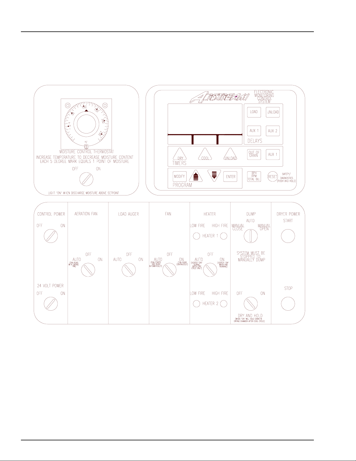
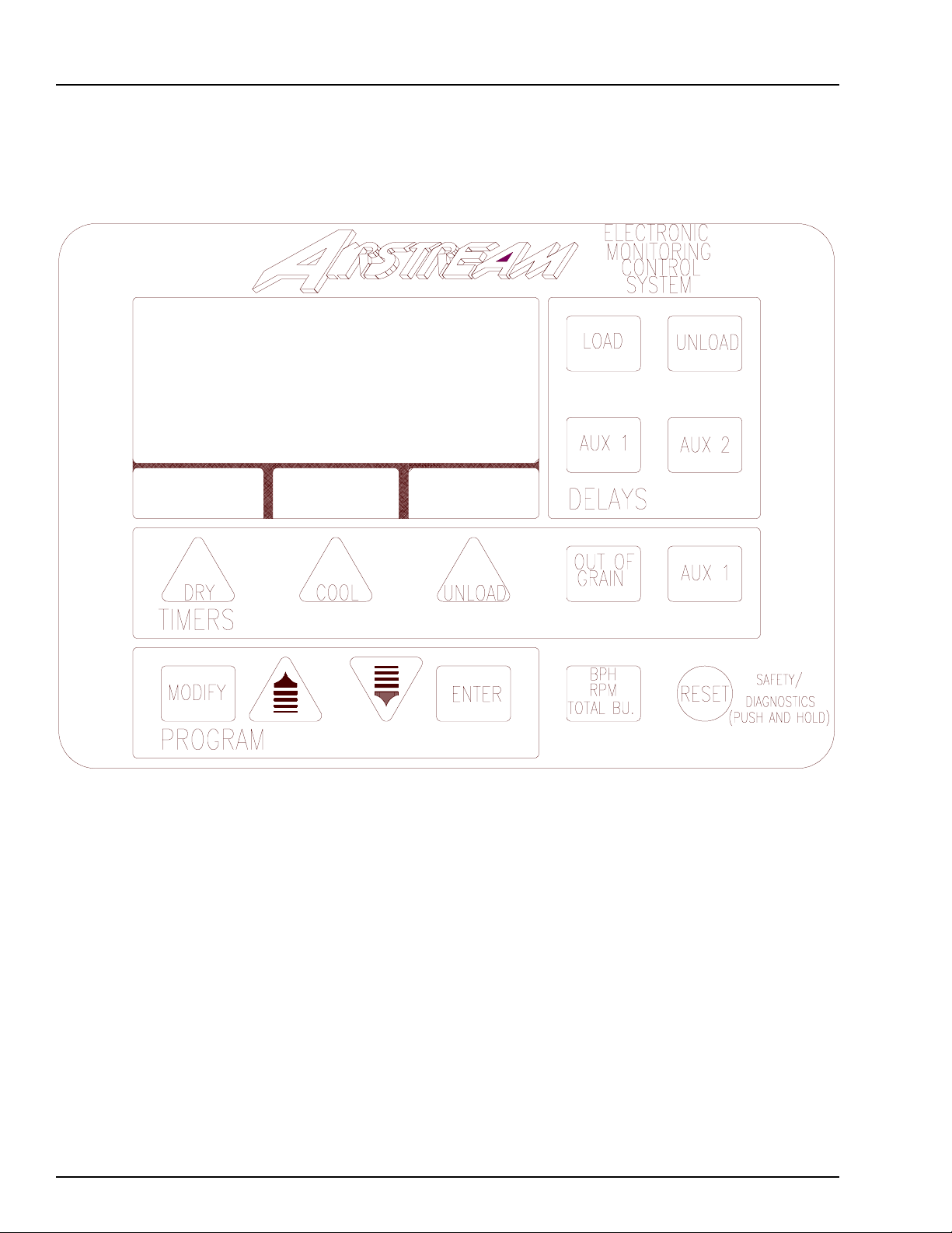
Dryer Control Panel Featuring the
Electronic Monitoring Control System
The control panel provides easy access to gauges
and controls, and the illuminated switches provide a
quick reference for every operating function. The
patent pending Electronic Monitoring Control
System is a computerized control system that gives
instant information regarding dryer operation.
Moisture Control Thermostat
This electronic thermostat controls the moisture
level of discharged grain by sensing grain column
temperature using the four (4) RTD temperature
sensors located in the drying chamber. The moisture
control thermostat indicates the current grain
temperature in the drying chamber with LEDs. The
grain temperature setpoint is set on the moisture
control thermostat. In the Autoflow mode, when the
grain temperature reaches the grain temperature
setpoint, and the dry timer has reached zero, the
dryer will dump the third driest portion of grain
from the drying chamber into the storage chamber.
In the Autobatch mode the dryer will dump all of the
grain into the storage chamber.
switch. The switch lights up when placed in the
on position. If the switch is placed in the on
position, and the light does not light up, make sure
that the emergency stop switches located on the
Autoflow control box is pulled out.
24-Volt Power Switch
This switch turns the power on or off to the actuator
control box. The switch lights up when placed in the
on position. If the switch is placed in the on
position, and the light does not light up, make sure
that the emergency stop switch located on the
actuator control box is pulled out (1997 model only).
Aeration Fan Switch
This switch controls the operation of the aeration fan
located at the bottom of the bin. The switch lights
up when the aeration fan comes on. When placed in
the auto position, the aeration fan starts and stops
with the main drying fans. When placed in the off
position, the aeration fan will not run. When placed
in the on position, the aeration fan comes on when
the dryer is running.
Load Auger Switch
Moisture Control Switch
This switch turns the power on or off to the moisture
control thermostat. When placed in the on
position, the dryer will not enter the dump cycle
until the grain temperature has reached the grain
temperature setpoint on the moisture control thermo-
stat and the dry timer has reached zero. When
placed in the on position, the moisture control
switch lights up when the grain temperature is below
the grain temperature set point on the moisture
control thermostat. When placed in the off
position, the dryer ignores the grain temperature and
operates strictly off the dry timer. When placed in
the off position, the moisture control switch does
not light up.
Control Power Switch
The power to the Electronic Monitoring Control
System is turned on or off with the control power
This switch controls the operation of the fill
system(s) that load grain into the drying chamber.
The switch lights up when the fill system(s) are
running. When placed in the auto position, the fill
system(s) start and stop automatically depending on
the level of grain relative to the drying chamber high
level rotary switch. When operating in the
Autobatch mode, the fill system(s) will shut off 2/3
(two-thirds) of the way through the dry cycle, even
if grain has not reached the drying chamber high
level rotary switch. When placed in the off
position ,the fill system(s) will not run. When
placed in the on position, the fill system(s) come
on and stay on when the dryer is running.
Fan Switch
This switch controls the operation of the main
drying fan(s). The switch lights up when the
airswitch located in the sidewall next to the master
11
Page 12

CONTROL SYSTEM
Dryer Control Panel, continued
Autoflow Operation
drying fan senses an increase in static pressure and
closes. In the Autoflow mode, when placed in the
auto position, the main drying fan(s) start when
grain reaches the drying chamber low level rotary
switch and do not stop until the dryer shuts down
or is stopped manually by pressing the stop switch.
In the Autobatch mode, the main drying fan(s)
shut off automatically in the dump cycle. When
placed in the off position, the main drying fan(s)
will not run. When placed in the on position, the
main drying fan(s) come on and stay on when the
dryer is running.
Fan Switch
This switch controls the operation of the main
drying fan(s). The switch lights up when the
airswitch located in the sidewall next to the master
drying fan senses an increase in static pressure and
closes. In the Autoflow mode, when placed in the
auto position, the main drying fan(s) start when
grain reaches the drying chamber low level rotary
switch and do not stop until the dryer shuts down
or is stopped manually by pressing the stop switch.
In the Autobatch mode the drying fan(s) will not
run. When placed in the on position, the main
drying fan(s) come on and stay on when the dryer
is running.
Dump Switch
This switch controls the operation of the linear
actuator housed in the actuator control box. The
switch lights up when the linear actuator is mov-
ing. When placed in the manual close position,
the linear actuator in the actuator control box
retracts, raising the dump chutes. When placed in
the auto position, the linear actuator extends at
the beginning of the dump cycle- lowering the
dump chutes, and retracts at the end of the dump
cycle, raising the dump chutes. When placed in
the manual open position, the linear actuator
extends, lowering the dump chutes. This switch is
disabled when the dryer is running. The dryer
must be stopped to manually dump.
Dry And Hold Switch
When placed in the on position, the grain in the
drying chamber will not be dumped into the
storage chamber at the end of the dry cycle, and
the dryer will stop. This switch can be used to
hold the last batch of grain in the drying chamber
and stop the dryer. When placed in the off
position, the dryer will operate normally. The
switch lights up when placed in the on position.
Heater Switch
This switch controls the operation of the
burner(s). The switch lights up when the burner is
on. When the burner is on, small lights above and
below the heater switch indicate if the burner(s)
are in high fire or low fire. In the Autoflow mode,
when placed in the auto position, the burner(s)
fire when grain reaches the drying chamber low
level rotary switch and do not stop until the dryer
shuts down or is stopped manually by pressing the
stop switch. In the Autobatch mode, the burner(s)
shut off automatically in the cool and dump cycle.
When placed in the off position, the burner(s)
will not fire. When placed in the on position,
the burner(s) fire anytime the main drying fan(s)
are running.
Dryer Power Start Switch
This switch starts and operates the dryer based on
switch settings. The switch lights up when the
dryer is running. The dump switch is disabled after
this switch has been pushed.
Dryer Power Stop Switch
This switch stops all dryer functions. If an auto-
matic dryer shutdown occurs, first determine and
correct the cause of the shutdown. Press the dryer
power stop switch to reset the dryer before starting.
12
Page 13

Autoflow Operation
CONTROL PANEL
13
Page 14
CONTROL SYSTEM
Electronic Monitoring Control System
Autoflow Operation
14
Page 15

Autoflow Operation
CONTROL SYSTEM
Electronic Monitoring
Control System
The Electronic Monitoring Control System
controls all timing functions and safety circuit
checks. It is designed to simplify dryer operation
by providing printed messages and warnings on its
liquid crystal display (LCD).
Turning On The Electronic Monitoring
Control System
Turn the control power switch to the on
position. The monitor will display a copyright
message, software version number, total running
time in hours and minutes and the model number,
and the serial number and current time and date.
When the serial number and current time and date
are displayed, press the reset button to activate the
controller and enter the main drying screen.
Setting The Dry, Cool And Unload Timers
These switches are used to set the dry, cool
and dump cycle times. The current settings on
these timers are displayed directly above their timer
button. To change the setting of these timers do the
following:
1) Press the dry, cool or unload timer
button.
2) Press the modify button.
3) Press the increase or decrease button to
adjust the settings.
4) Press the enter button.
5) To enter the new value into memory
immediately, press the reset button.
During operation, the remaining time on
each timer is displayed on the screen. If the power
goes out or the dryer is stopped, these times are
saved by the controller. When the dryer is restarted,
the timers will continue timing down. The timers
will return to their initial settings by pressing the
reset button. The cool timer is not used in an
Autoflow system.
Setting The Aux. 1 Timer
The value set on the aux. 1 timer acts as a
buffer to allow grain to fall away from the drying
chamber low level rotary switch after the drying
fans start without giving an error. When grain
reaches the drying chamber low level rotary
switch, the drying cycle starts (if the fan switch is
placed in the auto or on position) and the aux.
1 timer begins to time down. If grain falls away
from the drying chamber low level rotary switch
before the time on the aux 1 timer reaches zero, no
error is given and the dryer continues in the drying
cycle. If grain falls away from the drying chamber
low level rotary switch after the aux. 1 timer
reaches zero, a drying chamber no grain error is
given and the dryer shuts down. The aux. 1 timer
should be set long enough so that the fill system(s)
have sufficient time to make up the grain that falls
away from the drying chamber low level rotary
switch when the fan(s) and heater(s) start; but,
should not be set too long. If the linear actuator
fails to retract, the dump chutes and grain runs
directly from the drying chamber to the storage
chamber without being dried, then the grain would
fall away from the drying chamber low level
rotary switch and a drying chamber no grain error
would be given. If the aux. 1 timer is set too long
and the linear actuator failed to retract, an unac-
ceptable amount of wet grain could flow from the
drying chamber to the storage chamber before a
drying chamber no grain error is given and the
dryer shuts down. The aux. 1 timer is set using
the same procedure as the dry and unload timers,
but the reset button does not need to be pressed to
enter the new values into memory immediately.
Setting the Out of Grain Timer
The value set on the out of grain timer is
the amount of time that grain has to reach the
drying chamber low level rotary switch when the
dryer is refilling after the dump cycle in an
Autobatch system. When the dump cycle is
complete, the out of grain timer begins to count
down. If grain does not reach the drying chamber
low level switch before the out of grain timer
reaches zero, the dryer will give an out of grain
error and shut down. The out of grain timer is not
used in an Autoflow system.
15
Page 16

CONTROL SYSTEM
Autoflow Operation
Setting the Load Delay
The value set on the load delay is the amount
of time that fill system number two runs after grain
reaches the drying chamber high level rotary switch.
This delay is not used with only one fill system con-
trolled by the Autoflow. The load delay should be set
long enough so that the drying chamber high level
rotary switch is covered with enough grain that the fill
system do not start and stop frequently in the dry cycle
due to settling or shrinkage; but, the load delay should
be set short enough so that grain does not reach the
drying chamber overflow rotary switch. The load
delay is set using the same procedure as the dry and
unload timers, but the reset button does not need to be
pressed to enter the new values into memory immedi-
ately.
Setting the Aux. 1 Delay
In units that the Autoflow controls one fill
system, the value set on the aux. 1 delay is the amount
of time that fill system number one runs after grain
reaches the drying chamber high level rotary switch.
The aux.1 delay should be set long enough so that the
drying chamber high level rotary switch is covered
with enough grain that the fill system does not start and
stop frequently in the dry cycle due to settling or
shrinkage; but, the aux. 1 delay should be set short
enough so that grain does not reach the drying chamber
overflow rotary switch.
In units that the Autoflow controls two fill
systems, the value set on the aux. 1 delay is the amount
of time that fill system number one runs after fill
system number two shuts off. Fill system number one
is the fill system that directly puts grain in the drying
chamber. The aux. 1 delay should be set long enough
so that all grain present in fill system number one is
loaded into the drying chamber before it shuts off.
This will decrease the current required to start fill
system number one the next time the dryer calls for
grain. The aux. 1 delay is set using the same procedure
as the dry and unload timers, but the reset button does
not need to be pressed to enter the new values into
memory immediately.
Setting the Unload Delay
The value set on the unload delay is the
amount of time that both fill system number one
and fill system number two run after grain falls
away from the wet supply rotary switch before the
unit shuts down and gives a wet supply hopper
empty error. In units that the Autoflow controls
only one fill system, the value set on the unload
delay is the amount of time that fill system number
one runs after grain falls away from the wet supply
rotary switch. The unload delay should be set long
enough so that the fill system(s) clean out before
the dryer shuts down; but, should be set short
enough to avoid running the fill system (s) empty
for an excessive amount of time. The unload delay
is set using the same procedure as the dry and
unload timers, both the reset button does not need
to be pressed to enter the new values into memory
immediately.
Setting the Aux. 2 Delay
The aux. 2 delay is not currently being
used.
Viewing operation time and total cycles
The total operation time and total cycles
can be viewed at any time the dryer is in the main
drying screen by pressing the increase button.
Diagnostics Mode-Resetting Batch Counter
The Electronic Monitoring Control System
can perform a self-diagnostic exam. With the dryer
stopped and in the main drying screen, press and
hold down the reset button for several seconds.
After the self-diagnostic exam is complete, the
display will read the results of the exam and will
then give the user the option to reset the batch
counter. The batch counter can be cleared by
pressing the reset button or left as-so by pressing
the enter button. After choosing an option, the user
is taken to the shutdown history retrieval. To view
past shutdowns and the time and date the shutdown
occurred, press the decrease button. Press the enter
button at any time to return to the main drying
screen.
16
Page 17

Autoflow Operation
Set-up Mode
The set-up mode is used to program the
computer with different variables that influence how
the dryer will operate. With the dryer stopped and in
the main drying screen, press the increase and
decrease buttons at the same time to enter the set-up
mode.
CONTROL SYSTEM
recommended.
3). The third variable to set is the
dryer model. Use the increase and de-
crease buttons to select one of the four
model types that fits your system. The four
models are as follows:
1). The first variable to be set is the
number of fill system that are to be con-
trolled by the dryer. Use the increase and
decrease buttons to toggle between one
or two fill systems. Press the enter button
when the number of fill systems displayed
on the screen equals the number of fill
systems that the computer will be control-
ling. If one fill system is selected, only one
fill system will be controlled by the
computer. The aux. 1 delay will be used to
delay the shut off of the fill system after
the drying chamber is full. The load delay
will have no effect on the operation of the
fill system. If two fill systems are selected,
two fill systems will be controlled by the
computer. Both the load delay and the aux.
1 delay are used by the computer to delay
the shut-off of the fill system(s) after the
drying chamber is full.
2). The second variable to set is
whether the drying fan(s) will start with the
drying chamber high level or drying
chamber low level rotary switch. Use the
increase and decrease buttons to toggle
between starting the fan(s) with the high or
low level rotary switch. Press the enter
button when the correct rotary switch is
displayed. In most situations, the fan(s)
should be started with the drying chamber
low level rotary switch. If the drying
chamber high level rotary switch is se-
lected to control the starting of the main
drying fan(s), the dry cycle and main drying
fan(s) will not start until grain reaches the
drying chamber high level rotary switch.
Again, this mode of operation is not
AF2-Autoflow with two main drying fans
AF1-Autoflow with one main drying fans
AB2-Autobatch with two main drying fans
AB1-Autobatch with one main drying fans
Most systems will be either an
Autoflow with one fan or an Autoflow with
two fans. Press the enter button when the
correct model number is displayed.
4). The fourth variable is the current
year. Use the increase and decrease
buttons to select the correct year. Press the
enter button when the correct year is
displayed.
5). The fifth variable is the current
month. Use the increase and decrease
buttons to select the correct month. Press
the enter button when the correct month is
displayed.
6). The sixth variable is the current
day of the month. Use the increase and
decrease buttons to select the correct day of
the month. Press the enter button when the
correct day is displayed.
7). The seventh variable is the current
hour. Use the increase and decrease
buttons to select the correct hour. Press the
enter button when the correct hour is
displayed.
8). The eighth variable is the current
minute. Use the increase and decrease
buttons to select the correct minute. Press
the enter button when the correct minute is
17
Page 18

CONTROL SYSTEM
displayed.
Autoflow Operation
9). The ninth variable is the airswitch
test. Use the increase and decrease buttons
to toggle between yes or no. If no is
selected, the dryer does not require proof
of airflow before the burner lights. If yes
is selected, the dryer requires proof of
airflow to light the burner. Each time the
dryer control power is shut off, the
airswitch test defaults to yes.
10). The tenth variable is the fan delay.
The fan delay is the delay in seconds
between the starting of the master fan unit
and the slave fan unit. In systems with
220v 1-ph electrical power, the fan delay
should be set at small value, less than 3
seconds. If the fan delay is set too long,
the slave fan could rotate fast enough
backwards to start in a reverse rotation.
Use the increase and decrease buttons to
select the fan delay. Press the enter button
when the correct fan delay is displayed. In
single fan units the fan delay is not appli-
cable.
12). The twelfth variable is the status
of the wet grain and drying chamber low
level rotary switches. By pressing the dry
timer switch, the user can directly enter the
shutdown history retrieval. By pressing the
unload timer switch, the status of these two
rotary switches can be altered. Use the
increase and decrease buttons to make the
selection. Press the enter button when the
correct selection is displayed. When the
wet supply test is on, the dryer monitors the
wet supply rotary switch. When the wet
supply test is off, the dryer does not
monitor the wet supply rotary switch. The
computer responds as though there is wet
grain in the wet storage tank. When the
chamber low test is off, the dryer does not
monitor the drying chamber low level
rotary switch. The computer responds as
though there is grain in the drying chamber
against the low level rotary switch. When
the chamber low test is off, the display on
the dryer control panel reads yes at the
grain low level status line.
11). The eleventh variable is the high
flame delay. The high flame delay is the
amount of time the burner remains in low
fire on ignition. In normal operation the
high flame delay is set at one second. Use
the increase and decrease buttons to select
the high flame delay. Press the enter
button when the correct high flame delay
is displayed.
After the set-up mode is complete
the user is taken directly to the shutdown
history retrieval. To view past shutdowns
and the time and date the shutdown oc-
curred, press the decrease button. Press the
enter button at any time to return to the
main drying screen.
18
Page 19

Autoflow Operation
CONTROL SYSTEM
19
Page 20

CONTROL SYSTEM
Autoflow Operation
20
Page 21

Autoflow Operation
CONTROL SYSTEM
21
Page 22

CONTROL SYSTEM
Autoflow Operation
22
Page 23

Autoflow Operation
CONTROL SYSTEM
Dryer Status
By viewing the display on the dryer control
panel the user can quickly determine what mode of
operation the dryer is in, what cycle the dryer is in,
the location of grain relative to the drying chamber
rotary switches, and the current status of the dryer.
The Electronic Monitoring Control System flashes
the current status of the dryer on the display on the
dryer control panel. When the system is running,
information about the operation of the dryer and
the location of grain can be obtained with a quick
glance at the dryer control panel. The displayed
dryer conditions are as follows:
Batch Mode
When the display on the dryer control
panel reads batch mode, the dryer has been
programmed to operate as an automatic batch
dryer. When operating as an automatic batch dryer
all the grain in the drying chamber is dumped into
the storage chamber during the dump cycle, and a
cooling cycle is available after the dry cycle. This
is not the standard mode of operation. The user
must enter the set-up mode to change the dryer
model from AB1 or AB2 to AF1 or AF2, to
change from Autobatch to Autoflow.
Auto Mode
When the display on the dryer control
panel reads auto mode, the dryer has been
programmed to operate as an automatic staged
batch dryer. When operating as an automatic
staged batch dryer, only the driest third of grain is
removed from the drying chamber during the
dump cycle, and once the drying process starts it
does not stop until the dryer is stopped. This is the
standard mode of operation.
drying chamber has reached the drying chamber
high level rotary switch. If the load switch on the
dryer control panel is in the auto position, the fill
system(s) should be stopped or in the process of
stopping.
Grain High Level NO
When the display on the dryer control
panel reads grain high level no, the grain in the
drying chamber has not reached the drying
chamber high level rotary switch. If the load
auger switch on the dryer control panel is in the
on or auto position, the fill system(s) should
be running.
Grain Low Level YES
When the display on the dryer control
panel reads grain low level yes, the grain in the
drying chamber has reached the drying chamber
low level rotary switch. If the fan switch on the
dryer control panel is in the auto or on
position the dry timer begins to count down and
the dry cycle begins.
Grain Low Level No
When the display on the dryer control
reads grain low level no, the grain in the
drying chamber has not reached the drying
chamber low level rotary switch and the drying
process has not started.
Stopped
When the display on the dryer control
panel is flashing stopped the dryer is not
running. The set-up mode can be entered into
when the dryer status is stopped.
Grain High Level YES
When the display on the dryer control
panel reads grain high level yes, the grain in the
Purging
When the display on the dryer control
panel is flashing purging, the dryer is running,
23
Page 24

CONTROL SYSTEM
Autoflow Operation
the fan is running and there is proof of airflow, the
burner is getting ready to ignite.
Unload
When the display is flashing unload, the
dump chutes have been lowered and the dryer is in
the dump cycle.
Temp HLD
When the display on the dryer control
panel is flashing temp hld the dryer is in the dry
cycle, the dry timer has reached zero, and the
current grain temperature is below the grain
temperature setpoint on the moisture control
thermostat. If the dryer is stopped when temp
hld is flashing on the screen, two minutes will be
entered into the dry timer when the dryer is re-
started.
The Electronic Monitoring Control System dis-
plays the error message and sounds a warning
signal to alert the user. The displayed error condi-
tions and their electrical cause are as follows:
Burner 1 Warning Flame Not Detected
The flame sensor in burning number one
has failed to detect flame. Either the burner failed
to light or the flame sensor needs to be adjusted.
The flame sensor is the sensor attached to the
burner, and has a single lead. If the burner is
lighting but the unit it still shutting down; due to
loss of flame, the flame sensor needs to be ad-
justed. The flame sensor can be adjusted by
bending it so it is immersed in flame. If the burner
is not lighting, make sure that the dryer is getting
fuel, all solenoids are opening, and the ignitor is
sparking. Electrically there is a loss of 12vDC+ on
J1-9 on the input/output board.
Loading
When the display on the dryer control
panel is flashing loading, the fill system(s) are
running.
Drying
When the display on the dryer control
panel is flashing drying, the dryer is in the dry
cycle, the main drying fan(s) are running, and the
load augers are not running.
Cooling
When the display on the dryer control
panel is flashing cooling, the dryer has been set-
up as an Autobatch unit and is in the cool cycle.
Error Messages
When the dryer shuts down, the user can
quickly determine what caused the shutdown by
viewing the display on the dryer control panel.
Burner 2 Warning Flame Not Detected
The flame sensor in burner number two has
failed to detect flame. Either the burner failed to
light or the flame sensor needs to be adjusted. The
flame sensor is the sensor attached to the burner,
and has a single lead. If the burner is lighting but
the unit is still shutting down; due to loss of flame,
the flame sensor needs to be adjusted. The flame
sensor can be adjusted by bending it so it is im-
mersed in flame. If the burner is not lighting,
make sure that the dryer is getting fuel, all sole-
noids are opening, and the ignitor is sparking.
Electrically there is a loss of 12vDC+ on J1-10 on
the input/output board.
Burner 1-Vapor High Temperature
The LP gas vapor temperature sensor,
located on the gas pipe train downstream from the
vaporizer coil, on fan and heater number one has
opened, indicating that the vaporizer coil is run-
ning too hot and must be adjusted. This sensor is
set at 200 degrees Fahrenheit and automatically
24
Page 25

Autoflow Operation
CONTROL SYSTEM
resets itself when cool. The vaporizer is adjusted
by loosening the bolt and moving the vaporizer
coil away from the flame. Electrically there is a
loss of 12vDC+ on J1-5 on the input/output board.
Burner 2 Vapor High Temperature
The LP gas vapor temperature sensor
located on the gas pipe train downstream from the
vaporizer coil, on fan and heater number two has
opened, indicating that the vaporizer coil is run-
ning too hot and must be adjusted. This sensor is
set at 200 degrees Fahrenheit and automatically
resets itself when cool. The vaporizer is adjusted
by loosening the bolt and moving the vaporizer
coil away from the flame. Electrically there is a
loss of 12vDC+ on J1-6 on the input/output board.
Fan 1 Housing High Temperature
The temperature high limit, located on the
housing, on the fan and heater number one opened,
indicating that the housing towards the bin has
overheated. The high limit sensor is set at 200
degrees Fahrenheit and must be manually reset.
Electrically there is a loss of 12vDC+ on J1-7 on
the input/output board.
needs to be lowered, or the cycle setpoint on the
Hi-lo thermostat needs to be increased, if the error
is displayed frequently. Electrically there is a loss
of 12vDC+ on J1-11 on the input/output board.
12 volt power supply warning
The right circuit breaker, located on the
input/output board, has tripped.
L1 Voltage Lost
The left circuit breaker, located on the
input/output board, has tripped or one of the
hardware timers has shut down the dryer. The
overload must be reset manually. Electrically
there is a loss of 12vDC+ on J5-6, or J5-10 on the
input/output board.
Fan 1 Motor Overload
The thermal overload in the control box on
fan number one, has tripped, indicating an
overcurrent condition. The overload must be reset
manually. Electrically there is a loss of 12vDC+
on J4-12 on the input/output board.
Fan 2 Motor Overload
Fan 2 Housing High Temperature
The temperature high limit, located on the
housing, on fan and heater number two opened,
indicating that the housing towards the bin has
overheated. This high limit sensor is set at 200
degrees Fahrenheit and must be manually reset.
Electrically there is a loss of 12vDC+ on J1-8 on
the input/output board.
Plenum High Temperature
An over temperature condition has oc-
curred inside the dryer plenum. The plenum high
limit is set automatically on the Hi-Lo thermostat
when the cycle set-point is adjusted and resets
automatically when cooled. The lo-fire pressure
The thermal overload in the control box on
fan number two has tripped, indicating an
overcurrent condition. The overload must be reset
manually. Electrically there is a loss of 12vDC+
on J4-18 on the input/output board.
Fan Shutdown Loss of Airflow
The contacts on the airswitch, located in
the bin sidewall and attached to fan and heater
number one, have opened due to the fan not
turning, or the airswitch may need to be adjusted.
Electrically there is a loss of 12vDC+ on J1-13 on
the input/output board.
25
Page 26

CONTROL SYSTEM
Autoflow Operation
Drying Chamber Overflow
The grain level in the drying chamber has
reached the drying chamber overflow rotary
switch. Grain will have to be dumped from the
drying chamber to the storage chamber before the
unit can be restarted. This error indicates that
either the drying chamber high level rotary switch
is faulty or the time on the Load delay or Aux.1
delay needs to be lowered. Electrically there is the
presence of 12vDC+ on J4-6 on the input/output
board.
Storage Chamber Full
The grain level in the storage chamber has
reached the storage chamber high level rotary
switch located 3 feet(.91 meters) below the fan and
heater(s). Grain will have to be removed from the
storage chamber before the unit can be restarted.
Electrically there is the presence of 12vDC + on
J4-4 on the input/output board.
Wet Supply Hopper Empty
The grain in the wet supply tank has fallen
below the wet supply rotary switch. If there is
grain against the drying chamber low level rotary
switch, the dryer can be restarted by pressing the
stop switch to clear the error and then the start
switch. Electrically there is a loss of 12vDC+ on
J4-2 on the input/output board.
Wet Supply Empty Press<Enter>to
Dry Remaining Grain
This message is displayed when the start
button is pushed and grain has fallen away from
the wet supply rotary switch and there is still grain
against the drying chamber low level rotary
switch. If the enter button is pushed, the dryer will
restart, but the fill system(s) will not restart.
Electrically there is a loss of 12vDC+ on J4-2 and
the presence of 12vDC+ on J4-8 on the input/
output board.
Out of Grain Warning
This message is displayed after the dump cycle
when the dryer has been restarted by pressing the
enter button, after a wet supply empty error has
been given.
Cannot Start Dryer Wet Supply Empty
This message is displayed when the start button is
pushed and grain has fallen away from the wet
supply rotary switch and there is no grain against
the drying chamber low level rotary switch. Grain
will have to be put into the wet supply tank or the
drying chamber to start the dryer. Electrically
there is a loss of 12vDC on J4-2 and a loss of
12vDC+ on J4-8 on the input/output board.
Drying Chamber Low Grain
This message is displayed when grain falls
away from the drying chamber low level rotary
switch after the Aux. 1 timer has reached zero. If
the error is being caused due to the settling of
grain after the fans start, the time on the Aux.1
timer can be lengthened. Electrically there is a
loss of 12vDC+ on J4-8 on the input/output board.
Load Auger Motor Overload
The thermal overload in the fill system control box
for fill system number one has tripped, indicating
an overcurrent condition. Make sure the emer-
gency stop switch on the fill system control box is
pulled out as this will inhibit the motor starter
from engaging. The overload must be reset manu-
ally. Electrically there is a loss of 12vDC+ on J4-
16 on the input/output board.
26
Page 27

Autoflow Operation
CONTROL SYSTEM
Auxiliary Fill Motor Overload
The thermal overload, in the fill system control
box for fill system number two; has tripped,
indicating an over current condition. Make sure
the emergency stop switch on the fill system
control box is pulled out as this will inhibit the
motor starter from engaging. The overload must
be reset manually. Electrically there is a loss of
12vDC on J4-16 on the input/output board.
Aeration Fan Motor Overload
The thermal overload, in the fill system
control box for the aeration fan; has tripped,
indicating an overcurrent condition. Make sure the
emergency stop switch on the fill system control
box is pulled out as this will inhibit the motor
starter from engaging. The overload must be reset
manually. Electrically there is a loss 12vDC+ on
J4-17 on the input/output board.
Autoflow Fan and Heater Control Box
The Autoflow fan and heater control box
mounted on the fan heater unit(s), houses the
motor starter, Fenwall ignition-flame detection
board, and all circuitry involved with the control of
the fan and heater unit. Two service switches are
located on the front panel of the Autoflow fan and
heater control box.
Fan
This switch allows the user to turn off the
drying fan while at the fan and heater unit. It the
Autoflow is running, and the fan is running, the
fan will stop when the fan service switch is placed
in the off position, but the dryer will continue
running as though the fan was on. If the burner is
running when the fan service switch is placed in
the off position, the burner will shut off also.
The fan service switch light on the master fan
lights up when the airswitch closes. In normal
operation the fan service switch should be left in
the on position.
Heater
This switch allows the user to turn off the
burner while at the fan and heater unit. If the
Autoflow is running, and the burner is running, the
burner will stop when the heater service switch is
placed in the off position, but the dryer will
continue running as though the burner was on.
When the heater service switch is placed in the
off position, the fan does NOT shut off. When
the heater service switch is placed back to the on
position, the unit reignites after the purge delay.
The heater service switch light lights up when the
burner is on. In normal operation, the heater
service switch should be left in the on position.
27
Page 28

FILL SYSTEM CONTROL BOX
Autoflow Operation
28
Page 29

Autoflow Operation
Fill System Control Box
FILL SYSTEM CONTROL BOX
The fill system control box houses the
motor starters for fill system #1, fill system #2 and
the aeration fan. Start and stop switches are
located on the front of the fill system control box
and the emergency stop, and aeration fan lockout
switches are located on the side of the control box.
Fill System #1
These start and stop switches are used to
start and stop fill system #1 manually. In order to
use the start and stop switches for fill system #1,
the control power switch on the Autoflow control
box must be placed in the on position, and the
dryer must be stopped. When the start switch for
fill system #1 is pushed, fill system #1 starts and
will not shut off until the stop switch for fill
system #1 or the emergency stop switch is pushed.
When the dryer is running, the start and stop
switches for fill system #1 are disabled.
fan, the control power switch on the Autoflow
control box must be placed in theon position,
and the dryer must be stopped. When the start
switch for the aeration fan is pushed the aeration
fan is pushed, the aeration fan starts and will not
shut off until the stop switch for the aeration fan or
the emergency stop switch is pushed. When the
dryer is running, the start and stop switches for the
aeration fan are disabled.
Aeration Fan Lockout
This switch controls how the aeration fan
will operate in the event the Autoflow unit
stopped. If the aeration fan lockout switch is
placed in the continuos position, the aeration fan
will remain running after the Autoflow unit shuts
down. If the aeration fan lockout switch is placed
in the automatic position, the aeration fan shuts
off when the dryer stops.
Fill System #2
These start and stop switches are used to
start and stop fill system #2 manually. In order to
use the start and stop switches for fill system #2,
the control power switch on the Autoflow control
box must be placed in the on position, and the
dryer must be stopped. When the start switch for
fill system #2 is pushed, fill system #2 starts and
will not shut off until the stop switch for fill
system #2 or the emergency stop switch is pushed.
When the dryer is running the start and stop
switches for fill system #2 are disabled.
Aeration Fan
These start and stop switches are used to
start and stop the aeration fan manually. In order
to use the start and stop switches for the aeration
Emergency Stop Switch
This switch will stop all fill systems and
aeration fan(s) that are running when the emer-
gency stop switch is pushed. Note: that the emer-
gency stop switch only stops fill systems and
aeration fans that are controlled by the fill system
control box. If the dryer is running when the
emergency stop switch is pushed, the dryer will
stop along with any fill systems or aeration fans
that are running.
Pre-Season Check
Before the dryer is filled, thoroughly
inspect the unit and check the operation of the
dryer as follows on page 29. When entering the
bin take great caution. Never enter a bin where
grain is present.
29
Page 30

FILL SYSTEM CONTROL BOX
Set Control Switches
♦ MOISTURE CONTROL Switch On
♦ AERATION FAN Switch Off
♦ LOAD AUGER Switch Off
♦ FAN Switch Off
♦ HEATER Switch Off
♦ DUMP Switch Auto
♦ DRY and HOLD Switch Off
♦ Autoflow Emergency Stop Switch Out
♦ Actuator Emergency Stop Switch Out
♦ Fill System Control Box Emergency Stop Switch Out
♦ 24 VOLT POWER Switch On
Autoflow Operation
Control Power Switch
Turn the control power switch on. The
switch will light up. The screen will display a
copyright message and software version number,
total running time in hours and minutes and the
model number, and the serial number and current
time and date. At this time, the controller will lock
out all other dryer functions. Once the date and
time are displayed, press the reset button and the
dryer will perform its safety circuit check. If a
fault is found, an error message will be displayed
on the screen. If all are found safe, the main
drying screen will be displayed.
Drying Chamber
Enter the drying chamber and inspect each
dump hopper for obstructions that may inhibit the
flow of grain into the dump chutes. Make sure that
the gap between the discharge flow plates and the
floor sheets is a minimum of 1-1/2. All discharge
flow plates should be adjusted evenly around the
bin. Inspect each discharge flow plate and make
sure that the bottom brackets on each flow plate
have not collapsed, due to pressure from walking
around the drying chamber. Inspect the leveling
bands. Make sure that all leveling bands are
installed properly and are in good shape.
Rotary Switches
View the drying chamber switches from
the peak hole on top of the dryer. Make sure that
all three rotary switches are spinning freely.
Double check the seal on each rotary switch top.
The number one cause of switch failure is water.
Make sure when the electricain replaced the top on
the rotary switch that no creases formed in the
gasket. Inspect both the storage and wet supply
rotary switches for operation and proper seal.
Dump Chutes
Enter the storage chamber. Make sure that
all dump chutes are adjusted evenly. When one
chute is level, make sure that all chutes are level.
This is very critical to the correct operation of the
dryer. The center plate, that all the dump chute
chains attach to, should be no greater than 12
from the pulley when the chutes are level. If the
center plate is further than 12 from the pulley
when the chutes are closed, the chains must be
lengthened.
Linear Actuator
Turn the dump switch on the Autoflow
control box to the manual open position. Use a
30
Page 31

Autoflow Operation
FILL SYSTEM CONTROL BOX
tape measure to measure the stroke on the linear
actuator. The stroke should be between 12 and
14. If the stroke on the actuator is not 12 to 14,
the actuator should be adjusted. Make sure that all
pulleys and cables are able to move freely when
the actuator is moving. With the actuator ex-
tended, enter the storage chamber. View each
dump chute individually. Make sure that each
dump chute opened completely when the actuator
extended. If a dump chute does not open com-
pletely, the double nuts on the bolt that the chutes
hinge on, needs to be loosened. The dump chutes
should hinge smoothly. After the chutes have
been inspected turn the dump switch on the
Autoflow control box to the Auto position and
press the stop switch. The chutes should raise.
Power Start Button
Before the dryer start button is pushed,
make sure there is grain in the wet supply tank. If
there is no grain in the wet supply tank, the dryer
will not start. Push the dryer start button. The
screen should no longer be flashing STOPPED.
can easily be reversed by first turning off the
power at the main disconnect, then interchanging
any two of the three power supply wires coming
into the motor starter in the fan control box.
Reverse the two outside wires, L1 and L3, and
leave the middle one in the same position. If the
dryer is empty, the unit will not operate. The fans
cannot create enough static pressure to engage the
airswitch. You will receive a loss of airflow
message.
Aeration Fan
Bump the aeration fan switch on the
autoflow control box and observe the aeration fan
rotation. The aeration fan should run counter-
clockwise. Sometimes on three phase models the
motor will run backwards. This can easily be
reversed by first turning off the power at the main
disconnect, then interchanging any two of the three
power supply wires coming into the motor starter
in the fill system control box. Reverse the two
outside wires, L1 and L3, and leave the middle one
in the same position.
Fuel Check
If using LP gas, make sure the tank has
plenty of fuel. If using natural gas, make sure
adequate supply is available. If using LP gas,
slowly open the main fuel supply valve at the tank.
If using natural gas, turn on the valve along the
supply line. Then open the ball valve on the fan
heater unit(s). Inspect all gas lines and connec-
tions for possible leaks. Any gas leaks need to be
fixed immediately!
Fan
Make sure that the fan and heater service
switches on the main drying fan(s) are in the on
position. Bump the fan switch on the Autoflow
control box and observe the fan rotation. The fan
should run counterclockwise. Sometimes on three
phase models the motor will run backwards. This
Fill System
Prepare the wet storage tank to deliver
grain to the dryer. Make sure all personnel are
away from any machinery that is controlled by the
Autoflow. Place the load auger switch in the
Auto position. The fill system(s) should begin
to load grain from the wet supply tank to the dryer.
When the display on the Autoflow control box
reads GRAIN LOW LEVEL YES, close the
valve that supplies the fill system(s) with wet grain
from the wet supply tank. After the fill system(s)
have cleaned out, place the load auger switch in
the off position.
Airswitch
Place the fan and heater service switches
on the main drying fan(s) in the off position.
Place the fan switch on the Autoflow control box
31
Page 32

FILL SYSTEM CONTROL BOX
Autoflow Operation
in the on position. Place the aeration fan switch
on the Autoflow control box in the on position.
Go to the master fan and heater unit. Place the fan
service switch in the on position. The master
fan should start. In two fan, units the slave fan
should start after the fan delay. In single fan units
the light on the master fan service switch should
light up after the master fan reaches half speed. If
the service switch light lights up before the fan
reaches half speed, adjust the airswitch by turning
it clockwise. If the service switch light does not
light up, adjust the airswitch by turning it counter-
clockwise. In two fan units, the light on the master
fan service switch should light up after the slave
fan reaches half speed. If the service switch light
lights up before the fan reaches half speed, adjust
the airswitch by turning it clockwise. If the ser-
vice switch light does not light up, adjust the
airswitch by turning it counterclockwise.
Burner Test Fire
natural gas units. At this time adjust the Hi-Lo
thermostat all the way to the right. Watch the
thermometers. When the temperature in dryer gets
to the desired setpoint (160°-180°), turn the knob
back to the left until the heater cycles from high
fire to low fire. While the heater is in low fire,
adjust the low fire gas pressure by opening or
closing the valve located on top of the pipetrain.
The low fire gas pressure should be approximately
2-6 lbs. for LP units and 1-3 lbs. for natural gas
units. If the burner remains in low fire and does
not cycle, slightly decrease the gas pressure at the
low fire gas valve. Any time the high fire gas
pressure is adjusted, the low fire gas pressure
needs to be checked. The basic rule-of-thumb for
setting gas pressure is as follows: make sure that
the temperature in the bin is increasing at a rapid
rate when in high fire, and the temperature in the
bin is falling at a rapid rate while in the low fire.
Dryer Shutdown
Make sure the heater service switch on the
main drying fan(s) is in the off position. Place
the heater switch on the Autoflow control box in
the on position. Start the main drying fan(s), if
they are not already running. Make sure the fuel
supply is on. Go to the fan and heater unit(s) and
place the heater service switch in the on posi-
tion. The burner should ignite after a short purge
delay. Gas pressure should be shown on the
gauge. Adjust the high fire gas pressure by turning
the regulator in and out on LP units; or, by open-
ing and closing the main ball valve on natural gas
units. The high fire pressure should be approxi-
mately 6-15 lbs. for LP units and 6-10 lbs. for
To shut down the dryer, first close the fuel
supply valve at the tank or the valve along the fuel
supply line. If the burner is operating, let the dryer
run out of fuel. It should shut down due to loss of
flame. Press the dryer stop button to clear the
error, and turn off the main power disconnect at
the entrance panel.
Emergency
In case of an emergency push the emer-
gency stop switch located on the side of the
Autoflow control box. This will shut everything,
that is controlled by the dryer, off immediately.
32
Page 33

Autoflow Operation
Top Dry Autoflow Theory of Operation
THEORY OF OPERATION
Control Panel Switches Status:
Control Power: On
24v Power: On
Moisture Control Thermostat: On
Aeration Fan: Auto
Load Auger: Auto
Fan: Auto
Heater: Auto
Dump: Auto
Dry & Hold: Off
When the Top Dry is in a ready state; that
is, with no grain the Drying Chamber and wet
grain in the Wet Storage Tank, Fill System #1 and
Fill System #2 will start to fill the Drying Chamber
with wet grain when the start switch is pressed on
the Dryer Control Panel. In single fill system
units on Fill System #1 will start. When grain
reaches the Drying Chamber Low Level Rotary
Switch the Aeration Fan, and the Master Drying
Fan will come on, and the Fan Delay will start to
count down. When the Fan Delay reaches zero the
Slave Drying Fan will start, the Airswitch will
close, and the Dry Timer will start to count down.
In single fan units the Fan Delay will not count
down and the Airswitch will close after the Master
Drying Fan starts. After a twenty second Purge
Delay the fan/heater unit(s) will ignite. When the
Plenum Temperature reaches the Cycle Setpoint on
the Hi-Lo Thermostat the fan/heater unit(s) will
cycle to Low-Fire. When the Plenum Temperature
falls ten degrees below the Cycle Setpoint the fan/
heater unit(s) will cycle back to High-Fire. The
fan/heater unit(s) will continue to cycle throughout
the drying.
When grain reaches the Chamber High
Level Rotary Switch the Load Delay will begin to
count down. When the Load Delay reaches zero
Emergency Stop Switches Status
Autoflow Control Box Emergency Stop: pulled out
Fill System Control Box Emergency Stop: pulled out
Actuator Control Box Emergency Stop: pulled out
Aeration Fan Bypass: Continuos
Fill System #2 will shut off and the Aux. 1 Delay
will begin to count down. When the Aux. 1 Delay
reaches zero Fill System #1 will shut off.
If the Chamber High Level Rotary Switch
becomes exposed due to shrinkage of grain in the
Drying Chamber, the fill system(s) will start and
refill the Drying Chamber. When grain reaches
the Chamber High Level Rotary Switch the fill
system(s) will shut off after the delays.
When the Dry Timer reaches zero and the
Grain Temperature Setpoint on the Moisture
Control Thermostat has not been reached the unit
will go into Temperature Hold. When the grain
temperature reaches the Grain Temperature
Setpoint on the Moisture Control Thermostat the
unit will continue to the Dump Cycle. In the
Dump Cycle the Linear Actuator in the Actuator
Control Box extends, the dump chutes lower, and
grain is dumped from the Drying Chamber into
Storage Chamber. Immediately after the dump
chutes open the Unload Timer begins to count
down. When the Unload Timer reaches zero the
dump chutes raise and grain stops dumping from
the Drying Chamber into the Storage Chamber.
During the Dump Cycle, 1/3 of the grain is
dumped into the Storage Chamber.
33
Page 34

THEORY OF OPERATION
Autoflow Operation
After the Dump Cycle, the unit returns to
the beginning of the Dry Cycle, the Fill system(s)
refill the Drying Chamber and the process begins
again. If the Dry Timer reaches zero after the
grain temperature reaches the Grain Temperature
Setpoint on the Moisture Control Thermostat the
unit does not enter Temperature Hold. It goes
right to the Dump Cycle.
The unit continues with the same operation
until either no grain is present against the Wet
Supply Rotary Switch, or the Storage Chamber
becomes full.
If the Wet Storage Tank becomes empty
while the fill systems are running, the Unload
Delay starts to count down. When the Unload
Delay reaches zero the fill system(s) shut off
along with the dryer and a Wet Supply Hopper
Empty error is displayed on the Dryer Control
Panel screen. If there is grain against the Drying
Chamber Low Level Rotary Switch the unit can be
restarted by pressing the start switch. When the
start switch is pressed the screen on the Dryer
Control Panel will read Press Enter to Dry
Remaining Grain. If the enter button is pushed
the dryer will restart without running the fill
system(s). The dryer will remain running until the
completion of the next Dump Cycle, after which an
out of Grain error is displayed on the Dryer
Control Panel and the dryer stops.
If the Storage Chamber High-Limit Rotary
Switch becomes covered with grain during the
Dump Cycle the dryer will continue through the
Dump Cycle and will continue to the next Dry
Cycle. When the Dry Cycle is complete the unit
will not continue to the Dump Cycle. A Storage
Chamber Full error will be displayed on the
screen and the dryer will stop. The unit will not
dump automatically until grain has been removed
from the Storage Chamber.
If the dryer stops for any reason the Aera-
tion Fan Bypass switch is placed in the
continuos position. The Aeration Fan Bypass
switch is located in the side of the Fill System
Control Box. If the Aeration Fan Bypass switch is
placed in the automatic position the Aeration
Fan stops whenever the dryer stops.
Items In Italics Are Defined In the
Dryer Terminology Section.
Top Dry Autobatch
Theory of Operation
Control Panel Switches Status:
Control Power: On
24v Power: On
Moisture Control Thermostat: On
Aeration Fan: Auto
Load Auger: Auto
Fan: Auto
Heater: Auto
Dump: Auto
Dry & Hold: Off
34
Emergency Stop Switches Status
Autoflow Control Box Emergency Stop: pulled out
Fill System Control Box Emergency Stop: pulled out
Actuator Control Box Emergency Stop: pulled out
Aeration Fan Bypass: Continuos
continued on page 35
Page 35

Autoflow Operation
THEORY OF OPERATION
When the Top Dry is in a ready state; that
is, with no grain in the Drying Chamber and wet
grain in the Wet Storage Tank, Fill System #1 and
Fill System #2 will start to fill the Drying Chamber
with wet grain when the start switch is pressed on
the Dryer Control Panel. In single fill system
units only Fill System #1 will start. When grain
reaches the Drying Chamber Low Level Rotary
Switch the Aeration Fan , and the Master Drying
Fan will come on, and the Fan Delay will start to
count down. When the Fan Delay reaches zero the
Slave Drying Fan will start, the Airswitch will
close, and the Dry Timer will start to count down.
In single fan units the Fan Delay will not count
down and the Airswitch will close after the Master
Drying Fan starts. After twenty second Purge
Delay the fan/heater unit(s) will ignite. When the
Plenum Temperature reaches the Cycle Setpoint on
the Hi-Lo Thermostat the fan/heater unit(s) will
cycle to Low-Fire. When the Plenum Temperature
falls ten degrees below the Cycle Setpoint the fan/
heater unit(s) will cycle back to High-Fire. The
fan/heater unit(s) will continue to cycle throughout
the drying process.
When grain reaches the Chamber High
Level Rotary Switch the Load Delay will begin to
count down. When the Load Delay reaches zero
Fill System #2 will shut off and the Aux. 1 Delay
reaches zero Fill System #1 will shut off. If grain
does not reach the drying chamber high level
rotary switch before 2/3rds. of the dry cycle is
complete the fill systems will shut off automati-
cally.
If the Chamber High Level Rotary Switch
becomes exposed due to shrinkage of grain in the
Drying Chamber, the fill system(s) will start and
refill the Drying Chamber. When grain reaches
the Chamber High Level Rotary Switch the fill
system(s) will shut off after the delays.
When the Dry Timer reaches zero and the
Grain Temperature Setpoint on the Moisture
Control Thermostat has not been reached, the unit
will go into Temperature Hold. When the grain
temperature reaches the Grain Temperature
Setpoint on the Moisture Control Thermostat the
unit will continue to the Cool Cycle. In the Cool
Cycle the burner will shut off, the Cool Timer will
begin to count down, and the main drying fans will
continue to run, cooling the grain. When the Cool
Timer reaches zero the dryer will continue to the
Dump Cycle. In the Dump Cycle the main drying
fans will shut off, the Linear Actuator in the
Actuator Control Box extends, the dump chutes
lower, and grain is dumped from the Drying
Chamber into the Storage Chamber. Immediately
after the dump chutes open, the Unload Timer
begins to count down. When the Unload Timer
reaches zero the dump chutes raise. During the
Dump Cycle all of the grain is dumped into the
Storage Chamber.
After the Dump Cycle the unit returns to
the beginning of the Dry Cycle, the Out of Grain
Timer begins to count down, the fill system(s)
refill the Drying Chamber and the process begins
again. If grain does not reach the Drying Chamber
Low Level Rotary Switch before the Out of Grain
Timer reaches zero, the dryer will give an Out of
Grain error and shut down. If the Dry Timer
reaches zero after the grain temperature reaches
the Grain Temperature Setpoint on the Moisture
Control Thermostat the unit does not enter Tem-
perature Hold. If goes right to the Cool Cycle.
The unit continues with the same operation
until either no grain is present against the Wet
Supply Rotary Switch, or the Storage Chamber
becomes full.
If the Wet Storage Tank becomes empty
while the fill system(s) are running, the Unload
Delay start to count down. When the Unload
Delay reaches zero the fill system(s) shut off along
with the dryer and a Wet Supply Hopper Empty
error is displayed on the Dryer Control Panel
screen. If there is grain against the Drying Cham-
ber Low Level Rotary Switch the unit can be
continued on page 36
35
Page 36

THEORY OF OPERATION/TERMINOLOGY
Autoflow Operation
restarted by pressing the start switch. When the
start switch is pressed the screen on the Dryer
Control Panel will read Press Enter to Dry
Remaining Grain. If the enter button is pushed
the dryer will restart without running the fill
system(s). The dryer will remain running until the
completion of the next Dump Cycle, after which an
Out of Grain error is displayed on the Dryer
Control Panel and the dryer stops.
If the Storage Chamber High-Limit Rotary
Switch becomes covered with grain during the
Dump Cycle the dryer will continue through the
Dump Cycle and will continue to the next Dry
Cycle. When the Dry Cycle is complete the unit
will not continue to the Dump Cycle. A Storage
Top Dry Autoflow Terminology
Chamber Full error will be displayed on the
screen and the dryer will stop. The unit will not
dump automatically until grain has been removed
from the Storage Chamber.
If the dryer stops for any reason the Aera-
tion Fan will remain running if the Aeration Fan
Bypass switch is placed in the continuos posi-
tion. The Aeration Fan Bypass switch is located in
the side of the Fill System Control Box. If the
Aeration Fan Bypass switch is placed in the
automatic position the Aeration Fan stops
whenever the dryer stops.
Items in Italics are Defined in the
Dryer Terminology Section
Actuator Control Box-The actuator control box
houses the linear actuator that controls the dump
chutes. The actuator also houses the two 12vDC
batteries and the 24vDC battery charger. The
actuator control box is mounted to the bin
sidewall.
Aeration Fan-The aeration fan is located at the
bottom on the outside of the bin and is used to cool
grain in the storage chamber. The aeration fan is
designed to deliver about 1/4 cubic feet of air per
minute per bushel of grain in the storage chamber.
The motor starter for the aeration fan is located in
the Fill System Control Box.
Aeration Fan Bypass Switch-The aeration fan by
pass switch is located on the side of the fill system
control box. When the aeration fan bypass switch
is placed in the continuos position the aeration
fan does not shut off with the dryer. When the
aeration fan bypass switch is placed in the auto-
matic position the aeration fan shuts off when the
dryer stops.
Aux. 1 Delay-The aux. 1 delay is used in both
single fill and double fill systems. The aux. 1
delay is located on the dryer control panel next to
the display screen. In single fill systems the aux. 1
delay controls how long fill system #1 runs after
grain reaches the drying chamber high level rotary
switch. In units with two fill systems the aux. 1
delay controls how long fill system #1 runs after
fill system #2 shuts off. This allows fill system #2
to clean out before stopping.
Airswitch-The airswitch is used to tell the com-
puter when the drying fan(s) have started so the
burner can be ignited or remain ignited. The
airswitch is attached to the master drying fan and
is mounted in the bin sidewall even with the
master drying fan. The airswitch operates by
sensing the increase in static pressure in the bin
after the drying fan(s) have started. In two fan
units the airswitch should be adjusted so that it
does not close until after the slave fan reaches half
speed.
36
Page 37

Autoflow Operation
TERMINOLOGY
Cycle Setpoint-The cycle setpoint is the plenum
temperature that the fan and heater unit(s) will try
to maintain in the bin. The cycle setpoint is the
plenum temperature that the burner will cycle from
high-fire to low-fire. The cycle setpoint is set on
the hi-lo thermostat.
Cool Cycle-The cool cycle is the cycle that the
dryer enters into after the dry cycle is completed
on Autobatch units. The dryer will not enter into
the cool cycle until both the dryer timer has
reached zero and the grain temperature has reached
the grain temperature setpoint set on the moisture
control thermostat. If the moisture control thermo-
stat switch is placed in the off position the dryer
will ignore the grain temperature setpoint. During
the cool cycle the burner(s) are off an the main
drying fan(s) are running. When the cool timer
reaches zero the dryer enters the dump cycle.
There is not cool cycle on Autoflow units.
Cool Timer-The cool timer is located on the dryer
control panel below the display screen. On
Autobatch units it is a digital timer and controls
how long to cool the grain in the drying chamber
before dumping it into the storage chamber. There
is no cool timer on Autoflow units.
Dry Cycle-The dry cycle is the cycle that the dryer
is in when time is remaining on the dry timer or
when the dryer is in temperature hold. The dry
cycle start as soon as grain is above the drying
chamber low level rotary switch and the fan and
heater units are running.
Dry Timer-The dry timer is located on the dryer
control panel below the display screen. On
Autoflow units it is a digital timer and controls
how long to dry the grain in the drying chamber
before dumping it into the storage chamber. On
Autobatch units it controls how long to dry the
grain before cooling it in the cool cycle.
Dryer Control Panel-The dryer control panel is
located on the Autoflow Control Box. It con-
tains the start and stop switches and the selector
switches for the dryer. The dryer control panel
also contains the screen where the dyer status
and error messages are displayed.
Drying Chamber-The drying chamber is the
section of the dryer where the drying of grain
takes place. It is located in the upper chamber of
the dryer and is separated from the storage
chamber by a perforated drying floor. The fan
and heater unit(s) are located below the drying
floor and force air through the perforated floor to
dry the grain. Leveling bands in the drying
chamber keep the grain depth at 16.
Drying Chamber High Level Rotary Switch-
The drying chamber high level rotary switch is
one of three rotary switches located in the drying
chamber. The drying chamber high level rotary
switch has a shaft of medium length when
compared to the other two drying chamber rotary
switches. The drying chamber high level rotary
switch tells the computer when the drying
chamber is full so the fill system(s) can be
stopped, and also tells the computer when grain
is needed in the drying chamber so the fill
system(s) can be started.
Drying Chamber Low Level Rotary Switch-
The drying chamber low level rotary switch is
one of three rotary switches located in the drying
chamber. The drying chamber low level rotary
switch has the longest shaft of the three drying
chamber rotary switches. The drying chamber
low level rotary switch tells the computer when
grain has covered the peak in the drying chamber
so the drying fan(s) can start, and warns the
computer if the drying chamber were to empty
unexpectedly.
37
Page 38

TERMINOLOGY
Autoflow Operation
Drying Chamber Overflow Rotary Switch-The
drying chamber overflow rotary switch is one of
three rotary switches located in the drying cham-
ber. The drying chamber overflow rotary switch
has the shortest shaft of the three drying chamber
rotary switches. The drying chamber overflow
rotary switch warns the computer when grain is
getting too high in the drying chamber.
Dump Cycle-On Autoflow units the dump cycle is
the cycle entered into after completion of the dry
cycle. The dryer will not enter into the dump cycle
until both the dry timer has reached zero and the
grain temperature has reached the grain tempera-
ture setpoint set on the moisture control thermo-
stat. If the moisture control thermostat switch is
placed in the off position the dryer will ignore
the grain temperature setpoint. On Autobatch
units the dump cycle is entered into after the cool
cycle.
Fan Delay-The fan delay is not used in single fan
units. In two fan units it is the delay between the
starting of the master drying fan and the starting of
the slave drying fan. The fan delay is used to
prevent the excessive current draw experienced
when two large fan motors start at the same time.
The fan delay is programmed into the computer by
the user in the set-up mode detailed later.
Fill System #1-Fill system #1 is the fill system
that is controlled by the Autoflow and loads wet
grain directly into the drying chamber. Fill system
#1 is always present in an Autoflow system. The
motor starter for fill system #1 is located in the Fill
System Control Box.
Fill System #2-Fill system #2 is the fill system
that is controlled by the Autoflow and loads grain
into fill system #1. Fill system #2 shuts down in
normal operation before fill system #1 to allow fill
system #1 to clean out before it shuts off. Fill
system #2 is not required for proper operation of
the Autoflow unit; however, the computer must be
instructed on the number of fill systems the unit
has. This is done in the set-up mode detailed later.
The motor starter for fill system #2 is located in
the Fill System Control Box.
Fill System Control Box-The fill system control
box houses the motor starters for the fill system(s)
and the aeration fan. The fill system control box
also has start and stop switches which can operate
the fill system(s) and aeration fan manually when
the dryer is not running. The fill system control
box is mounted on the bin sidewall.
Grain Temperature Setpoint-On Autoflow units
the grain temperature setpoint is the temperature
that the grain must reach before the dryer will
continue from the dry cycle to the dump cycle. On
Autobatch units the grain temperature setpoint is
the temperature that the grain must reach before
the dryer will continue to the cool cycle. The grain
temperature setpoint is set at the moisture control
thermostat on the dryer control panel.
High-Fire-High fire is the state the burner is in
when the plenum temperature is below the cycle
setpoint set on the hi-lo thermostat. When the unit
is in high-fire the plenum temperature should be
on an upward climb. When the unit is in high-fire
the gas pressures should be set around 15 lbs. for
liquid propane units and 6 lbs. for natural gas
units. The gas pressures required to obtain the
desired temperature rise may vary with ambient air
conditions.
Hi-Lo Thermostat-The hi-lo thermostat is used
by the unit to monitor the current plenum tempera-
ture. The cycle setpoint is set on the hi-lo thermo-
stat. The hi-lo thermostat is also responsible for
monitoring the plenum high limit detailed later.
The hi-lo thermostat is attached to the master
drying fan and is mounted on the bin sidewall even
with the master drying fan. In two fan units do not
mount the hi-lo thermostat between the master and
slave fan and heater units.
38
Page 39

Autoflow Operation
TERMINOLOGY
Linear Actuator-The linear actuator is attached to
the cable that controls the dump chutes. When the
dryer enters into the dump cycle the linear actuator
extends giving slack to the dump chute cable.
When slack is given to the dump chute cable the
dump chutes open dumping grain from the drying
chamber into the storage chamber. The linear
actuator is located in the actuator control box.
Load Delay-The load delay is not used in single
fill systems. The load delay is located on the dryer
control panel next to the display screen. The load
delay controls how long fill system #2 runs after
grain has reached the chamber high level rotary
switch in units with two fill systems.
Low-Fire-Low-fire is the state the burner is in
when the plenum temperature meets or exceeds the
cycle setpoint on the hi-lo thermostat. When the
unit is in low-fire the plenum temperature should
be declining. When the unit is in low-fire the gas
pressure should be set around 5 lbs. for liquid
propane and 2 lbs. for natural gas. The gas pres-
sure required to make the temperature fall in the
plenum may vary with ambient air conditions.
Master Drying Fan-The master drying fan is
located on the fan platform just beneath the drying
chamber on the outside of the bin and is used to
force heated air through the grain to dry it. The
master drying fan is the only fan and heater in a
single fan unit. In two fan units the master drying
fan is the fan and heater with airswitch and hi-lo
thermostat.
Moisture Control Thermostat-The moisture
control thermostat is located on the dryer control
panel. The moisture control thermostat uses four
temperature sensors located in the drying chamber
to sense the grain temperature. The grain tempera-
ture setpoint is set on the moisture control thermo-
stat.
grain timer is the amount of time that grain has to
reach the drying chamber low level rotary switch
when the dryer is refilling after the dump cycle in
an Autobatch system. When the dump cycle is
complete the out of grain timer begins to count
down. If grain does not reach the drying chamber
low level switch before the out of grain timer
reaches zero the dryer will give an out of grain
error and shut down. The out of grain timer is not
used in an Autoflow system. The out of grain
timer is located on the dryer control panel next to
the display.
Plenum Temperature-The plenum temperature
is the temperature of the air coming out of the fan
and heater unit(s) that is being forced through the
grain in the drying chamber. The plenum tem-
perature is sensed by the hi-lo thermostat.
Purge Delay-The purge delay is a built-in delay
used to prevent the ignition of the burner with
raw gas in the bin. After proof of airflow has
been established the computer starts counting
down the purge delay to allow the fans to dis-
perse any gases that may have accumulated in the
bin before igniting. When the purge delay
reaches zero the burner ignites and the drying
begins. The purge delay is not set by the user.
Slave Drying Fan-The slave drying fan is not
present in single fan units. In two fan units the
slave drying fan is the fan and heater without the
airswitch and hi-lo thermostat.
Storage Chamber-The storage chamber is the
chamber where grain is cooled and stored. Hot
dry grain is dumped from the drying chamber into
the storage chamber during the dump cycle. A
rotary switch warns the computer when the
storage chamber is full.
Storage Chamber High Level Rotary Switch-
Out of Grain Timer-The value set on the out of
continued to page 40
39
Page 40

TERMINOLOGY/START UP PROCEDURE
Autoflow Operation
The storage chamber high level rotary switch is
located in the storage chamber 3, below the fan
and heater unit(s). The storage chamber high level
rotary switch warns the computer when the storage
chamber is full.
Temperature Hold-Temperature hold is the state
the dryer is in when the dry timer has reached zero
but the grain temperature on the moisture control
thermostat has not reached the grain temperature
setpoint. The dryer will not enter into temperature
hold unless the moisture control thermostat switch
is placed in the on position. When the dryer is
in temperature hold temp hold will be displayed
on the screen on the dryer control panel.
Unload Delay-The unload delay is used in both
single fill and double fill systems. The unload
delay is located on the dryer control panel next to
the display screen. In single fill systems the
unload delay controls how long fill system #1 runs
after the wet supply tank is emptied. In units with
two fill systems the unload delay controls how
long fill system #1 and fill system #2 run after the
wet supply tank is emptied.
Unload Timer-The unload timer is located on the
dryer control panel below the display screen. It is
a digital timer and controls how long the dump
chutes remain open during the dump cycle. The
setting of the unload timer will be detailed later.
Wet Storage Tank-the wet storage tank tempo-
rarily stores the wet grain that is to be loaded into
the drying chamber and dried. A wet storage tank
can be a hopper tank or a flat bottom bin.
Wet Supply Rotary Switch- The wet supply
rotary switch is located in the wet storage tank.
The wet supply rotary switch warn the computer
when the wet storage tank is empty.
Start Up Procedure
At the beginning of each harvest and before
filling the dryer will grain make sure to inspect the
dryer for rodent damage, and system integrity.
Enter the drying chamber and check each dump
hopper. Remove any obstructions. Test operate
the dryer using the pre-season checklist.
There are two fundamental things to control
with the Autoflow Top Dry (or any dryer); the
drying rate and the grain flow rate, and the drying
air temperature. We consider the best temperature
to be the highest one where the desired grain
quality is maintained. Corn used for live stock
consumption is dried at a maximum recommended
temperature of 200° Fahrenheit. Corn used for
different applications, and other grains may require
lower drying temperatures. By selecting a drying
air temperature a drying rage is established. To
achieve a desired final grain moisture content, the
grain flow rate is adjusted to match the drying rate.
Initial Dryer Start Up
1) Be sure the control power switch is off.
Turn on the main power supply disconnect
for the Autoflow control box, fan and
heaters, and all fill systems.
2) Pull out the emergency stop switches on
the Autoflow control box, fill systems
control box, and the actuator control box.
3) Set the switches on the Autoflow control
box as follows:
Moisture Control switch On
Aeration Fan switch Auto
Load Auger switch Off
Fan switch Auto
Heater switch Auto
Dump switch Auto
Dry and Hold switch Off
24 Volt Power switch On
40
Page 41

Autoflow Operation
START UP PROCEDURE
4) Make sure there is wet grain in the wet
supply tank.
5) Turn the control power switch to the
on position.
6) The screen will display a copyright mes-
sage and software version number, total
running time in hours and minutes and the
model number, and the serial number and c
current time and date.
7) When the serial number and current time
and date are displayed press the reset
button twice to get to the main drying
screen. The screen should read
STOPPED. The chamber high level and
the chamber low level should both read
NO.
8) Set the dry timer using the following charts
for specific bin size, fan and heater size,
drying temperature and grain input mois-
ture content.
11) Press the reset button for timer changes to
take effect immediately.
12) Set the grain temperature setpoint on the
moisture control thermostat chart below.
13) Press the start switch on the dryer control
panel.
14) CAUTION! Be sure all personnel are clear
of fill systems. Place the load auger switch
on the dryer control panel to the auto
position.
15) The fill system(s) should start immediately.
16) When the grain reaches the drying chamber
low level rotary switch the fan and
heater(s) should start.
17) When the grain reaches the drying chamber
low level rotary switch reaches the drying
chamber high level rotary switch, the fill
system(s) should stop.
9) Set the unload timer as follows:
18 diameter bin=30 seconds
21 diameter bin=33 seconds
24 diameter bin=36 seconds
27 diameter bin=39 seconds
30 diameter bin=42 seconds
36 diameter bin=48 seconds
10) Set all other delays and timers as pre-
scribed in the Electronic Monitoring
Control section of this manual.
180° drying temperature = 100° grain temperature setpoint
170° drying temperature = 103° grain temperature setpoint
160° drying temperature = 105° grain temperature setpoint
150° drying temperature = 108° grain temperature setpoint
140° drying temperature = 110° grain temperature setpoint*
130° drying temperature = 113° grain temperature setpoint*
120° drying temperature = 115° grain temperature setpoint*
18) When the dry timer reaches zero display
should read TEMP HOLD
19) When the grain temperature reaches the
grain temperature setpoint on the moisture
control thermostat the dryer should con-
tinue to the dump cycle.
20) The dump chutes should lower, grain
should dump from the drying chamber into
the storage chamber, and the fill system(s)
should start.
*When drying at a
temperature lower
than 150° the grain
temperature setpoint
on the moisture
control thermostat
may require a lower
setting at night.
41
Page 42

START UP PROCEDURE/LAST FILL
Autoflow Operation
Start Up Procedure cont.
21) After the dump cycle the dryer should
continue to the beginning of the next dry
cycle.
22) Just before the second dump go into the
drying chamber.
23) Place your arm in the grain next to the
outside leveling band post.
24) When the dump cycle begins your arm
should travel from the outside leveling
band post to the bin sidewall. If your arm
does not make it to the sidewall, increase
the time on the unload timer. If your arm
reaches the bin sidewall before the dump
cycle stops, decrease the time on the
unload timer. (This only has to be done
one time).
adjusted, decrease the time on the dry timer
by one-half. The dry timer should not be
set lower than the amount of time it takes
the dryer to refill after the dump cycle.
31) Restart the dryer. The time on the dry
timer should expire before the grain
reaches the temperature setpoint on the
moisture control thermostat.
32) Any time a change is made on the moisture
control thermostat the dryer must dump
four times before the full effect of the
change will be made on the moisture of the
grain.
Last Fill
1) Stop the dryer when all the wet grain has
been loaded into the drying chamber.
25) After the fourth dump stop the dryer.
26) Enter the storage chamber and gather a
large sample of grain. Gather a good
sample of grain all the way around the bin.
27) Test the moisture of the sample grain.
28) If the moisture of the grain is too high
increase the grain temperature setpoint on
the moisture control thermostat five de-
grees for each additional point of moisture
to be removed.
29) If the moisture of the grain is too low
decrease the grain temperature setpoint on
the moisture control thermostat five de-
grees for each additional point of moisture
to be added.
30) After the moisture control thermostat is
2) Set the time on the dry timer for twice the
recommended amount using the following
charts for the specific bin size, fan and
heater size, drying temperature and grain
input moisture content.
3) Push the reset button.
4) Turn the dry and hold switch to the on
position.
5) Turn the load auger switch to the off
position.
6) Press the start switch.
7) When the dryer shuts down install the fan
inlet cover(s).
8) Let the aeration fan cool in the top and
store, or manually dump into the storage
chamber.
42
Page 43

Autoflow Operation
3 hp 18"
l
3 hp 18"
l
3 hp 18"
l
3 hp 18"
l
3 hp 18"
l
3 hp 18"
l
DRYING RATES
TOP DRY AUTOFLOW SERIES
DRYING RATES FOR SHELLED CORN
AUTO FLOW SERIES
FAN & Plenum Moisture Minutes Minutes Minutes Minutes Minutes Minutes
HEATER Temperature Content Between Between Between Between Between Between
Unit(s) (fahrenheit) Wet Basis BU/HR Dumps BU/HR Dumps BU/HR Dumps BU/HR Dumps BU/HR Dumps BU/HR Dumps
10 - 12 H.P.
36" FAN
3.5 MILLION
BTU/HR
Inline Centrifuga
10-16 H.P.
36" FAN
4.5 MILLION
BTU/HR
Inline Centrifuga
10-16 H.P.
42" FAN
5.75 MILLION
BTU/HR
Inline Centrifuga
20 H.P.
42" FAN
6.75 MILLION
BTU/HR
Inline Centrifuga
30 H.P.
42" FAN
8.75 MILLION
BTU/HR
Inline Centrifuga
40 H.P.
42" FAN
10.25 MILLION
BTU/HR
Inline Centrifuga
160 25% 254 25.2 462 24.6 496 29.1
180 25% * 325 * 19.7 591 19.2 634 22.7
200 25% * 381 * 16.8 * 692 * 16.4 * 743 * 19.4
160 25% 271 23.6 316 27.6 334 34.1 343 42.0 559 25.8
180 25% 347 18.4 404 21.5 * 428 * 26.6 * 439 * 32.8 715 20.1
200 25% 406 15.7 * 474 * 18.4 * 501 * 22.7 * 514 * 28.0 837 17.2
160 25% 370 23.5 411 27.7 432 33.4
180 25% 473 18.4 * 525 * 21.6 * 552 * 26.1
200 25% * 554 * 15.7 * 615 * 18.5 * 647 * 22.3
160 25% 428 26.6 449 32.1
180 25% 547 20.8 575 25.0
200 25% 641 17.7 * 673 * 21.4
160 25% 469 24.3 480 30.0
180 25% 600 19.0 615 23.4
200 25% 702 16.2 720 20.0
160 25% 548 26.3
180 25% 701 20.5
200 25% 821 17.5
18' Dia. 1-Fan 21' Dia. 1-Fan 24' Dia. 1-Fan 24' Dia. 2-Fan 27' Dia. 1-Fan 27' Dia. 2-Fan
20% 401 15.9 729 15.6 783 18.4
30% 159 40.4 288 39.5 310 46.6
20% * 513 * 12.4 933 12.2 1,002 14.4
30% * 203 * 31.5 369 30.9 396 36.4
20% * 601 * 10.6 * 1,092 * 10.4 * 1,173 *12.3
30% * 238 * 26.9 * 432 * 26.3 * 464 * 31.1
20% 428 14.9 499 17.4 528 21.6 541 26.6 882 16.3
30% 169 37.8 197 44.2 209 54.6 214 67.4 349 41.3
20% 548 11.6 639 13.6 * 675 * 16.8 * 692 * 20.8 1,129 12.7
30% 217 29.5 253 34.5 * 267 * 42.6 * 274 * 52.6 446 32.3
20% 642 9.9 * 748 * 11.6 * 791 * 14.4 * 811 * 17.7 1,321 10.9
30% 254 25.2 * 296 * 29.5 * 313 * 36.4 * 321 * 44.9 523 27.6
20% 584 14.9 648 17.5 682 21.1
30% 231 37.7 256 44.4 270 53.5
20% 748 11.6 * 830 * 13.7 * 872 * 16.5
30% 296 29.5 * 328 * 34.7 * 345 * 41.8
20% * 875 * 9.9 * 971 * 11.7 * 1,021 * 14.1
30% * 346 * 25.2 * 384 * 29.6 * 404 * 35.7
20% 675 16.8 710 20.3
30% 267 42.6 281 51.3
20% 864 13.1 908 15.8
30% 342 33.3 359 40.1
20% 1,012 11.2 * 1063 * 13.5
30% 400 28.4 * 421 * 34.3
20% 740 15.4 758 19.0
30% 293 38.9 300 48.0
20% 947 12.0 970 14.8
30% 375 30.4 384 37.5
20% 1,109 10.2 1,136 12.6
30% 439 25.9 449 32.1
20% 865 16.6
30% 342 42.1
20% 1,107 13.0
30% 438 32.9
20% 1,296 11.1
30% 513 28.1
*Insufficient burner BTUs for 45 deg. ambient
temp.
Est. at ambient temp 45 deg. F, rel.humidity
65%
1/4 cfm
cooling
Use only as a guide, conditions will vary
capacities.
43
Page 44

5-7 hp 24"
5-7 hp 24"
5-7 hp 24"
5-7 hp 24"
5-7 hp 24"
5-7 hp 24"
TOP DRY AUTOFLOW SERIES
TOP DRY AUTOFLOW SERIES
Autoflow Operation
AUTO FLOW SERIES
FAN & Plenum Moisture Minutes Minutes Minutes Minutes
HEATER Temperature Content Between Between Between Between
Unit(s) (fahrenheit) Wet Basis BU/HR Dumps BU/HR Dumps BU/HR Dumps BU/HR Dumps
160 25% 519 34.3
10 - 12 H.P.
36" FAN
3.5 MILLION
BTU/HR
Inline Centrifugal 30% * 486 * 36.6
10-16 H.P.
36" FAN
4.5 MILLION
BTU/HR
Inline Centrifugal 30% * 330 * 53.9 * 557 * 32.0 * 589 * 43.5
10-16 H.P.
42" FAN
5.75 MILLION
BTU/HR
Inline Centrifugal 30% * 421 * 42.2 * 684 * 26 * 752 * 34.1
20 H.P.
42" FAN
6.75 MILLION
BTU/HR
Inline Centrifugal 30% * 446 * 39.9 * 803 * 31.9
30 H.P.
42" FAN
8.75 MILLION
BTU/HR
Inline Centrifugal 30% 478 37.2 486 52.8 861 29.8
40 H.P.
42" FAN
10.25 MILLION
BTU/HR
Inline Centrifugal 30% 545 32.6 563 45.5
*Insufficient burner BTUs for 45 deg.
ambient temp.
180 25% * 664 * 26.8
200 25% * 777 * 22.9
160 25% 353 50.4 595 29.9 629 40.7
180 25% * 451 * 39.4 761 23.4 805 31.8
200 25% * 529 * 33.6 * 891 * 19.9 * 943 * 27.2
160 25% 450 39.5 731 24.3 803 31.9
180 25% * 576 * 30.9 936 19.0 1,028 24.9
200 25% * 674 *26.4 * 1,096 * 16.2 * 1,204 * 21.3
160 25% 477 37.3 858 29.8
180 25% 610 29.1 1,098 23.3
200 25% * 714 * 24.9 * 1,286 * 19.9
160 25% 511 34.8 519 49.4 920 27.8
180 25% 653 27.2 664 38.6 1,177 21.7
200 25% 765 23.2 777 32.9 1,378 18.6
160 25% 583 30.5 602 42.6
180 25% 746 23.8 770 33.3
200 25% 873 20.3 902 28.4
30' Dia. 1-Fan 30' Dia. 2- Fan 36' Dia. 1-Fan 36' Dia. 2-Fan
20% 819 21.7
30% 324 54.9
20% * 1,048 * 16.9
30% * 415 * 42.9
20% * 1,227 * 14.5
20% 557 31.9 939 18.9 993 25.8
30% 220 80.8 371 47.9 393 65.2
20% * 713 * 24.9 1,202 14.8 1,271 20.1
30% * 282 * 63.1 475 37.4 503 51.0
20% * 835 * 21.3 * 1,407 * 12.6 * 1,488 * 17.2
20% 711 25.0 1,154 15.4 1,269 20.2
30% 281 63.3 457 39.0 502 51.1
20% * 909 * 19.5 1,477 12.0 1,623 15.8
30% * 360 * 49.5 584 30.4 642 39.9
20% * 1,065 * 16.7 * 1,730 * 10.2 * 1,901 * 13.4
20% 753 23.6 1,355 18.9
30% 298 59.8 536 47.8
20% 963 18.4 1,734 14.7
30% 381 46.7 686 37.4
20% * 1,128 * 15.7 * 2,030 * 12.6
20% 806 22.0 819 31.3 1,452 17.6
30% 319 55.8 324 79.1 574 44.6
20% 1,032 17.2 1,048 24.4 1,858 13.8
30% 408 43.6 415 61.8 735 34.8
20% 1,208 14.7 1,227 20.8 2,176 11.7
20% 920 19.3 950 26.9
30% 364 48.9 376 68.2
20% 1,178 15.1 1,216 21.0
30% 466 38.2 481 53.3
20% 1,379 12.9 1,424 18.0
Est. at ambient temp 45 deg. F, rel.humidity
65%
Use only as a guide, conditions will vary
1/4 cfm
44
Page 45

Autoflow Operation
We, The GSI Group, Inc.
1004 E. Illinois St.
Assumption, IL 62510
Declare that the products
Thingy, Model A-1, Serial No 123, and
Thingy, Model A-2, Serial Nos 45 to 67, snf
Thingy, Model A-3, All Serial Nos
Are in compliance with the following directives:
EMC Directive 89/336/EEC Amended 92/31 and 93/68
Low Voltage Directive 73/23/EEC
Machine Directive 89/392/EEC
DECLARATION OF CONFORMITY
Declaration of Conformity
?
____________________ ______________
Printed Name Date
The person signing the document must have sufficient authority to ensure that the provisions required
for the Declaration of Conformity are carried out.
The EMC Test Report and any other supporting documentation must be maintained by the manufacturer,
or his authorized representative for, at least, ten years.
45
Page 46

WARRANTY
THE GSI GROUP, INC. (GSI) WARRANTS ALL PRODUCTS MANUFACTURED BY GSI TO BE FREE
OF DEFECTS IN MATERIAL AND WORKMANSHIP UNDER NORMAL USAGE AND CONDITIONS
FOR A PERIOD OF 12 MONTHS AFTER RETAIL SALE TO THE ORIGINAL END USER OF SUCH
PRODUCTS. GSIS ONLY OBLIGATION IS, AND PURCHASERS SOLE REMEDY SHALL BE FOR GSI,
TO REPAIR OR REPLACE, AT GSIS OPTION AND EXPENSE, PRODUCTS THAT, IN GSIS SOLE
JUDGMENT, CONTAIN A MATERIAL DEFECT DUE TO MATERIALS OR WORKMANSHIP. ALL DE-
LIVERY AND SHIPMENT CHARGES TO AND FROM GSIS FACTORY WILL BE PURCHASERS RE-
SPONSIBILITY. EXPENSES INCURRED BY OR ON BEHALF OF THE PURCHASER WITHOUT PRIOR
WRITTEN AUTHORIZATION FROM AN AUTHORIZED EMPLOYEE OF GSI SHALL BE THE SOLE RE-
SPONSIBILITY OF THE PURCHASER.
EXCEPT FOR THE ABOVE STATED EXPRESS LIMITED WARRANTIES, GSI MAKES NO WARRANTY
OF ANY KIND, EXPRESSED OR IMPLIED, INCLUDING, WITHOUT LIMITATION, WARRANTIES OF
MERCHANTABILITY OR FITNESS FOR A PARTICULAR PURPOSE OR USE IN CONNECTION WITH (i)
PRODUCT MANUFACTURED OR SOLD BY GSI OR (ii) ANY ADVICE, INSTRUCTION, RECOMMENDA-
TION OR SUGGESTION PROVIDED BY AN AGENT, REPRESENTATIVE OR EMPLOYEE OF GSI REGARD-
ING OR RELATED TO THE CONFIGURATION, INSTALLATION, LAYOUT, SUITABILITY FOR A PAR-
TICULAR PURPOSE, OR DESIGN OF SUCH PRODUCT OR PRODUCTS.
Autoflow Operation
IN NO EVENT SHALL GSI BE LIABLE FOR ANY DIRECT, INDIRECT, INCIDENTAL OR CONSE-
QUENTIAL DAMAGES, INCLUDING, WITHOUT LIMITATION, LOSS OF ANTICIPATED PROFITS OR
BENEFITS. PURCHASERS SOLE AND EXCLUSIVE REMEDY SHALL BE LIMITED TO THAT STATED
ABOVE, WHICH SHALL NOT EXCEED THE AMOUNT PAID FOR THE PRODUCT PURCHASED. THIS
WARRANTY IS NOT TRANSFERABLE AND APPLIES ONLY TO THE ORIGINAL PURCHASER. GSI SHALL
HAVE NO OBLIGATION OR RESPONSIBILITY FOR ANY REPRESENTATIVE OR WARRANTIES MADE
BY OR ON BEHALF OF ANY DEALER, AGENT OR DISTRIBUTOR OF GSI.
GSI ASSUMES NO RESPONSIBILITY FOR FIELD MODIFICATIONS OR ERECTION DEFECTS WHICH
CREATE STRUCTURAL OR STORAGE QUALITY PROBLEMS. MODIFICATIONS TO THE PRODUCT NOT
SPECIFICALLY COVERED BY THE CONTENTS OF THIS MANUAL WILL NULLIFY ANY PRODUCT
WARRANTY THAT MIGHT HAVE BEEN OTHERWISE AVAILABLE.
THE FOREGOING WARRANTY SHALL NOT COVER PRODUCTS OR PARTS WHICH HAVE BEEN
DAMAGED BY NEGLIGENT USE, MISUSE, ALTERATION OR ACCIDENT. THIS WARRANTY COVERS
ONLY PRODUCTS MANUFACTURED BY GSI. THIS WARRANTY IS EXCLUSIVE AND IN LIEU OF ALL
OTHER WARRANTIES EXPRESS OR IMPLIED. GSI RESERVES THE RIGHT TO MAKE DESIGN OR SPECI-
FICATION CHANGES AT ANY TIME.
PRIOR TO INSTALLATION, PURCHASER HAS THE RESPONSIBILITY TO RESEARCH AND COM-
PLY WITH ALL FEDERAL, STATE AND LOCAL CODES WHICH MAY APPLY TO THE LOCATION AND
INSTALLATION.
46
Page 47

Autoflow Operation
1004 E. Illinois St.
Assumption, IL 62510
Phone 217-226-4421
Fax 217-226-4498
May 1998
THIS EQUIPMENT SHALL BE
INSTALLED IN ACCORDANCE WITH THE
CURRENT INSTALLATION CODES AND
APPLICABLE REGULATIONS WHICH
SHOULD BE CAREFULLY FOLLOWED IN
ALL CASES. AUTHORITIES HAVING
JURISDICTION SHOULD BE CONSULTED
BEFORE INSTALLATIONS ARE MADE.
47
 Loading...