

Page 1
2003 Series 2000
Autoflow Operation
Software Version 2.15
PNEG-696
PNEG-696
Page 2

Page 3

Series 2000 Autoflow Operation
Roof Damage Warning and Disclaimer.............................................................................4
Safety.............................................................................................................................5
Safety Precautions........................................................................................................6
Safety Sign-Off Sheet...................................................................................................7
Electrical Power Supply................................................................................................8
Electronic Monitoring Control System..............................................................................9
Dryer Control Panel..............................................................................................10
Set-Up Standard...................................................................................................14
Set-Up Extended...................................................................................................15
Fill System Control Box..............................................................................................18
Error Messages.............................................................................................................20
Pre-Season Checks......................................................................................................24
Top Dry Autoflow Theory of Operation.....................................................................27
Start Up Procedure......................................................................................................29
TopDry Autoflow Drying Rates for Shelled Corn......................................................32
TopDry Batch Drying Rates for Shelled Corn............................................................33
Warranty.....................................................................................................................34
TABLE OF CONTENTS
3
Page 4
SAFETY
Series 2000 Autoflow Operation
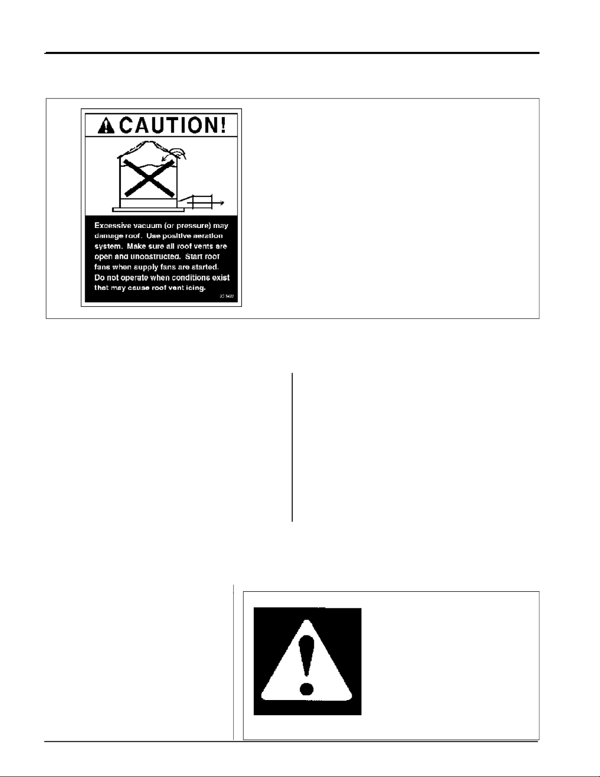
Roof Damage Warning and Disclaimer
GSI DOES NOT WARRANT ANY ROOF DAMAGE
CAUSED BY EXCESSIVE VACUUM OR INTERNAL PRESSURE FROM FANS OR OTHER AIR
MOVING SYSTEMS. ADEQUATE VENTILATION
AND/OR "MAKEUP AIR" DEVICES SHOULD BE
PROVIDED FOR ALL POWERED AIR HANDLING
SYSTEMS. GSI DOES NOT RECOMMEND THE
USE OF DOWNWARD FLOW SYSTEMS (SUCTION). SEVERE ROOF DAMAGE CAN RESULT
FROM ANY BLOCKAGE OF AIR PASSAGES.
RUNNING FANS DURING HIGH HUMIDITY/
COLD WEATHER CONDITIONS CAN CAUSE AIR
EXHAUST OR INTAKE PORTS TO FREEZE.
Fan/Heater Installation & Operating Instructions
Thank you for choosing a Top Dry Series Autoflow.
It is designed to give excellent performance and service for many years.
This manual describes the installation for all
standard production Top Dry Series 2000 single fan,
multi-fan and 2000 Series Heater Control units. Different models are available for liquid propane or
natural gas fuel supply, with either single phase 230
volt, or three phase 208, 220, 380, 460 or 575 volt
electrical power.
The principal concern of the GSI Group, Inc.
("GSI") is your safety and the safety of others asso-
The symbol shown is used to call your
attention to instructions concerning
your personal safety. Watch for this
symbol; it points out important safety
precautions. It means "ATTENTION",
"WARNING", "CAUTION", and
"DANGER". Read the message and
be cautious to the possibility of personal injury or death.
ciated with grain handling equipment. This manual
is written to help you understand safe operating
procedures, and some of the problems that may be
en-countered by the operator or other personnel.
As owner and/or operator, it is your responsibility to know what requirements, hazards and precautions exist, and to inform all personnel associated with the equipment, or who are in the fan area.
Avoid any alterations to the equipment. Such alterations may produce a very dangerous situation,
where serious injury or death may occur.
Safety Alert Symbol
WARNING! BE ALERT!
Personnel operating or working
around electric fans should read this
manual. This manual must be
delivered with the equipment to its
owner. Failure to read this manual
and its safety instructions is a
misuse of the equipment.
4
Page 5
Series 2000 Autoflow Operation
Grain Systems, Inc. recommends contacting your local
power company, and having a
representative survey your installation so the wiring is compatible
with their system, and adequate
power is supplied to your unit.
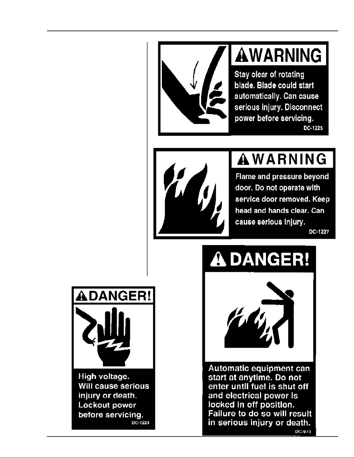
Safety decals should be read
and understood by all people in
the grain handling area. The rotating blade, fire warning decals
and voltage danger decal must be
displayed on the fan can. The bottom right decal should be present
on the inside bin door cover of
the two ring door, 24" porthole
door cover and the roof manway
cover.
If a decal is damaged or is
missing contact:
Grain Systems, Inc.
1004 E. Illinois St.
Assumption, IL 62510
217-226-4421
A free replacement will be sent to
you.
SAFETY
5
Page 6

SAFETY PRECAUTIONS
READ THESE INSTRUCTIONS
BEFORE OPERATION AND SERVICE
SAVE FOR FUTURE REFERENCE
1.
Read and understand the operating manual before trying to operate the
dryer.
2.
Power supply should be OFF for service of electrical components. Use
CAUTION in checking voltage or other procedures requiring power to
be ON.
3.
Check for gas leaks at all gas pipe connections. If any leaks are detected, do not operate the dryer. Shut down and repair before further
operation.
4.
Never attempt to operate the dryer by jumping or otherwise bypassing
any safety devices on the unit.
5.
Set pressure regulator to avoid excessive gas pressure applied to burner
during ignition and when burner is in operation. Do not exceed maximum recommended drying temperature.
6.
Keep the dryer clean. Do not allow fine material to accumulate in the
plenum or drying chamber.
Series 2000 Autoflow Operation
Use Caution in the
Operation of this
Equipment
The design and manufacture of this
dryer is directed toward operator
safety. However, the very nature of
a grain dryer having a gas burner,
high voltage electrical equipment
and high speed rotating parts, does
present a hazard to personnel, which
can not be completely safeguarded
against, without interfering with efficient operation and reasonable access to components.
Use extreme caution in working
around high speed fans, gas-fired
heaters, augers and auxiliary conveyors, which may start without
warning when the dryer is operating on automatic control.
7.
Use CAUTION in working around high speed fans, gas burners, augers
and auxiliary conveyors which START AUTOMATICALLY.
8.
Do not operate in any area where combustible material will be drawn into
the fan.
9.
Before attempting to remove and reinstall any propellor, make certain to
read the recommended procedure listed within the servicing section of
the manual.
10.
Clean grain is easier to dry. Fine material increases resistance to airflow
and requires removal of extra moisture.
This product is intended for the use of grain handling only. Any other
use is considered a misuse of the product.
Some edges of the product components can be sharp. It is recommended
that each component of this product be examined to determine if there
are any safety considerations to be taken. Any and all necessary personal
protective equipment should be worn at all tines when handling, assembling, installing and operation of the product and/or components.
Guards are removed for illustration purpose only. All guardsmust be in
place before/during operation.
KEEP THE DRYER CLEAN
DO NOT ALLOW FINE
MATERIAL TO ACCUMULATE
IN THE PLENUM CHAMBER
OR SURROUNDING THE
OUTSIDE OF THE DRYER
Continued safe, dependable operation of automatic equipment depends, to a great degree, upon the
owner. For a safe and dependable
drying system, follow the recommendations within this manual, and
make it a practice to regularly inspect the operation of the unit for
any developing problems or unsafe
conditions.
Take special note of the safety precautions listed above before attempting to operate the dryer.
6
Page 7

Series 2000 Autoflow Operation
SAFETY SIGN-OFF SHEET
________________________________________________________________________________________________________________________
_________________________________________________________________________________________________________________________
________________________________________________________________________________________________________________
___________________________________________________________________________________________________________________________
________________________________________________________________________________________________________________________
_____________________________________________________________________________________________________________________________
__________________________________________________________________________________________________________________________
_______________________________________________________________________________________________________________________________
_____________________________________________________________________________________________________________________________
______________________________________________________________________________________________________________________________
___________________________________________________________________________________________________________________________
Date
Employer’s Signature
Employee
______________________________________________________________________________________________________________________
_________________________________________________________________________________________________________________________
_____________________________________________________________________________________________________________________
______________________________________________________________________________________________________________________
_________________________________________________________________________________________________________________________
______________________________________________________________________________________________________________________
_______________________________________________________________________________________________________________________
______________________________________________________________________________________________________________________
______________________________________________________________________________________________________________________
_____________________________________________________________________________________________________________________
________________________________________________________________________________________________________________________
______________________________________________________________________________________________________________________
_____________________________________________________________________________________________________________
_______________________________________________________________________________________________________________________
_____________________________________________________________________________________________________________________
___________________________________________________________________________________________________________________
7
Page 8
ELECTRICAL POWER SUPPLY
Power Supply
An adequate power supply and proper wiring are important factors for maximum performance and long life of
the dryer. Electrical service must be adequate enough to
prevent low voltage damage to motors and control circuits (see Electrical Load Information).
Transformer and Wiring Voltage Drop
It is necessary to know the distance from the unit to the
available transformer, and the horsepower of your fan
unit. Advise the service representative of your local power
supplier that an additional load will be placed on the line.
Each fan motor should be wired through a fused or circuit breaker disconnect switch. Check on KVA rating of
transformers, considering total horsepower load. The
power supply wiring, main switch equipment and transformers must provide adequate motor starting and operating voltage. Voltage drop during motor starting should
not exceed 14% of normal voltage, and after motor is
running at full speed it should be within 8% of normal
voltage. Check Electrical Load Information for HP ratings and maximum amp loads to properly size wire and
fusing elements. Standard electrical safety practices and
codes should be used. (Refer to National Electrical Code
Standard Handbook by National Fire Protection Association).
Machine to Earth Grounding
It is very important that a
Rod
be installed at the fan. This is true even if there is
a ground at the pole 15 feet away. Place the ground
rod that comes standard, within 8 feet of the dryer
and attach it to the dryer control panel with at least a
#6 solid, bare, copper ground wire and the clamp provided. The grounding rod located at the power pole
will not provide adequate grounding for the dryer. The
proper grounding will provide additional safety in case
of any short and will ensure long life of all circuit
Machine To Earth Ground
Series 2000 Autoflow Operation
boards, and the ignition system. The ground rod must
be in accordance with local requirements.
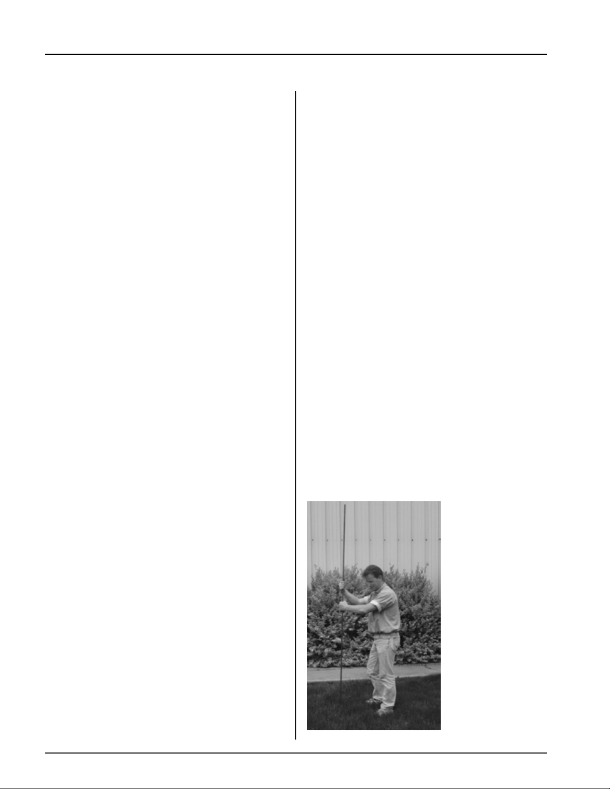
Proper Installation of Ground Rod
It is not recommended that the rod be driven into dry
ground.
Follow these instructions for proper installation:
1.
Dig a hole large enough to hold 1 to 2 gallons of
water.
2.
Fill hole with water.
3.
Insert rod through water and jab it into the ground.
4.
Continue jabbing the rod up and
ter will work its way down the hole, making
it possible to work the rod completely into
the ground. This method of installing the
rod gives a good conductive bond with the sur
rounding soil.
5.
Connect the bare, copper
rod with the proper
Figure 8.
6.
Connect the bare copper ground wire to the fan
control boxes with a grounding lug.
7.
Ground wire must not have any
splices.
ground rod clamp. See
down. The wa
ground
wire to the
breaks or
Dig a hole large
enough to hold 1
or 2 gallons of
water. Work
the ground rod
into the earth
until it is com-
pletely in the
ground.
8
Page 9
Series 2000 Autoflow Operation
Electronic Monitoring Control System
CONTROL PANEL
9
Page 10

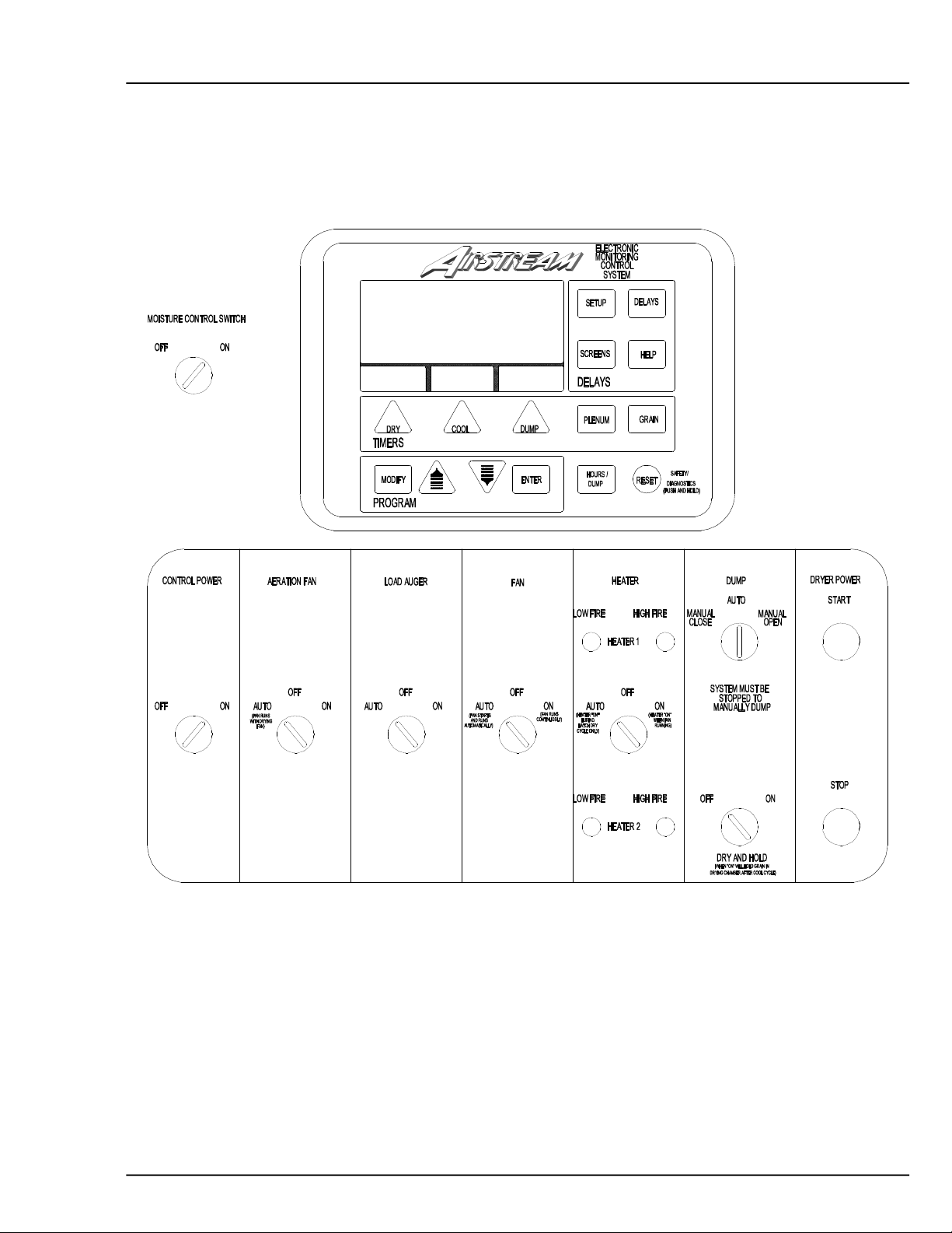
CONTROL PANEL
Series 2000 Autoflow Operation
Dryer Control Panel Featuring the
Electronic Monitoring Control System
The control panel provides easy access to gauges and
controls, and the illuminated switches provide a quick
reference for every operating function. The patent
pending Electronic Monitoring Control System is a
computerized control system that gives instant information regarding dryer operation.
Moisture Control Switch
This switch determines if the grain temperature
setpoint is used in the operation of the dryer. When
placed in the “on” position the dryer will not enter the
dump cycle until the grain temperature has reached the
grain temperature setpoint and the dry timer has
reached zero. When placed in the “on” position the
moisture control switch lights up when the grain
temperature is below the grain temperature setpoint.
When placed in the “off” position the dryer ignores the
grain temperature and operates strictly off of the dry
timer. When placed in the “off” position the moisture
control switch does not light up.
the “on” position the aeration fan comes on when the
dryer is running.
If the Aeration Fan Bypass is enabled in the Set-up, the
aeration fan remains running when the aeration fan
switch on the dryer control panel is placed in the “on”
position. With the aeration fan switch placed in the
“auto” position the aeration fan will stop any time the
dryer stops.
Load Auger Switch
This switch controls the operation of the fill system(s)
that load grain into the drying chamber. The switch
lights up when the fill system(s) are running. When
placed in the “auto” position the fill system(s) start and
stop automatically depending on the level of grain
relative to the drying chamber high level rotary switch.
When operating in the Autobatch mode the fill
system(s) will shut off 2/3 of the way through the dry
cycle even if grain has not reached the drying chamber
high level rotary switch. When placed in the “off”
position the fill system(s) will not run. When placed in
the “on” position the fill system(s) work the same as in
Auto, except the Out of Grain Timer is ignored.
Control Power Switch
The power to the Electronic Monitoring Control
System is turned on or off with the control power
switch. The switch lights up when placed in the “on”
position. If the switch is placed in the “on” position
and the light does not light up make sure that the
emergency stop switches located on the Autoflow
control box, and Fill System control box are pulled out.
Aeration Fan Switch
This switch controls the operation of the aeration fan
located at the bottom of the bin. The switch lights up
when the aeration fan comes on. When placed in the
“auto” position the aeration fan starts and stops with
the main drying fans. When placed in the “off”
position the aeration fan will not run. When placed in
Fan Switch
This switch controls the operation of the main drying
fan(s). The switch lights up when the airswitch located
in the sidewall next to the master drying fan senses an
increase in static pressure and closes. In the Autoflow
mode, when placed in the “auto” position the main
drying fan(s) start when grain reaches the drying
chamber low level rotary switch and do not stop until
the dryer shuts down or is stopped manually by pressing the stop switch. In the Autobatch mode the main
drying fan(s) shut off automatically in the dump cycle.
When placed in the “off’ position the main drying
fan(s) will not run. When placed in the “on” position
the main drying fan(s) come on and stay on when the
dryer is running.
10
Page 11

Series 2000 Autoflow Operation
Heater Switch
CONTROL PANEL
This switch controls the operation of the burner(s).
The switch lights up when the burner is on. When
the burner is on small lights above and below the
heater switch indicate if the burner(s) are in high
fire or low fire. In the Autoflow mode, when
placed in the “auto” position, the burner(s) fire
when grain reaches the drying chamber low level
rotary switch and do not stop until the dryer shuts
down or is stopped manually by pressing the stop
switch. In the Autobatch mode the burner(s) shut
off automatically in the cool and dump cycle.
When placed in the “off” position the burner(s)
will not fire. When placed in the “on” position the
burner(s) fire anytime the main drying fan(s) are
running.
Dump Switch
This switch controls the operation of the linear
actuator housed in the actuator control box. The
switch lights up when the linear actuator is moving. When placed in the “manual close position”
the linear actuator in the actuator control box
retracts- raising the dump chutes. When placed in
the “auto” position the linear actuator extends at
the beginning of the dump cycle- lowering the
dump chutes, and retracts at the end of the dump
cycle- raising the dump chutes. When placed in
the “manual open” position the linear actuator extendslowering the dump chutes.
Dry And Hold Switch
When placed in the “on” position the grain in the
drying chamber will not be dumped into the storage
chamber at the end of the dry cycle, and the dryer will
stop and cool for as long as the cool timer is set. If no
cooling is desired set to 0. This switch can be used to
hold the last batch of grain in the drying chamber and
stop the dryer. When placed in the “off” position the
dryer will operate normally. The switch lights up when
placed in the “on” position.
Dryer Power Start Switch
This switch starts and operates the dryer based on
switch settings. The switch lights up when the dryer is
running. The dump switch is disabled after this switch
has been pushed.
Dryer Power Stop Switch
This switch stops all dryer functions. If an automatic
dryer shutdown occurs, first determine and correct the
cause of the shutdown. Then, press the dryer power
stop switch to reset the dryer before starting.
11
Page 12

CONTROL SYSTEM CONTROL SYSTEM
CONTROL SYSTEM
CONTROL SYSTEM CONTROL SYSTEM
Electronic Monitoring Control System
Series 2000 Autoflow OperationSeries 2000 Autoflow Operation
Series 2000 Autoflow Operation
Series 2000 Autoflow OperationSeries 2000 Autoflow Operation
12
Page 13

Series 2000 Autoflow Operation
CONTROL SYSTEM
Electronic Monitoring Control System
The Electronic Monitoring Control System
controls all timing functions and safety circuit checks.
It is designed to simplify dryer operation by providing
printed messages and warnings on its liquid crystal
display (LCD).
Turning On The Electronic Monitoring Control
System
Turn the control power switch to the “on”
position. The monitor will display a copyright message, software version number and will enter the main
drying screen.
Setting The Dry, Cool And Unload Timers
These switches are used to set the dry, cool and
dump cycle times. The current settings on these timers
are displayed directly above their timer button. To
change the setting of these timers do the following:
1) Press the dry, cool or unload timer button.
2) Press the modify button.
3) Press the increase or decrease button to
adjust the settings.
4) Press the enter button.
5) To enter the new value into memory imme
diately, press the reset button.
Setting The Delays
The Following Delays are set by pressing the
Delays Button
WET BIN SWITCH DELAY - If the Wet
Supply Rotary Switch is exposed this delay must expire
before a warning is given.
REFILL DELAY - The REFILL DELAY is
used only on batch units. It is the amount of time that
the unit has to refill after the dump cycle. If the unit
does not refill before the time on the refill delay is at
zero the unit will give a “dry chamber empty” error.
This delay is not shown in Autoflow Mode.
HI LEVEL SW DELAY - The value set on the
HI LEVEL SW delay is the amount of time that fill
system runs after grain reaches the drying chamber
high level rotary switch. The HI LEVEL SW delay
should be set long enough so that the drying chamber
high level rotary switch is covered with enough grain
that the fill system does not start and stop frequently in
the dry cycle due to settling or shrinkage; but, the HI
LEVEL SW delay should be set short enough so that
grain does not reach the drying chamber overflow
rotary switch.
During operation the remaining time on each
timer is displayed on the screen. If the power goes out
or the dryer is stopped these times are saved by the
controller. When the dryer is restarted the timers will
continue timing down. The timers will return to their
initial settings by pressing the reset button. The Cool
Timer is not used on A Autoflow system except when in
Cool Down Mode. The Cool Timer is used to determine
how long the Top Dry will cool at shutdown. If no Cool
Down is desired set Timer to 0. Upon any of the
following conditions the system will go into cool down
mode.
1) Out Of Grain Timer Warning
2) Storage Chamber Full Warning
3) Low Level Switch Exposed Warning
4) Wet Bin Switch Exposed Warning
13
Page 14

CONTROL SYSTEM
Series 2000 Autoflow Operation
FILL 1 DELAY - This delay is not used in units with
only one fill system controlled by the Autoflow. The
value set on the fill 1 delay is the amount of time that fill
system number one runs after grain reaches the drying
chamber high level rotary switch.
LOW LEVEL DELAY - The value set on the
low level delay acts as a buffer to allow grain to fall
away from the drying chamber low level rotary switch
after the drying fans start without giving an error.
When grain reaches the drying chamber low level
rotary switch the drying cycle starts (if the fan switch is
placed in the “auto” or “on” position) and the low level
delay begins to time down. If grain falls away from the
drying chamber low level rotary switch before the time
on the low level delay reaches zero no error is given
and the dryer continues in the drying cycle. If grain falls
away from the drying chamber low level rotary switch
after the low level delay reaches zero a low level
switch exposed error is given and the dryer shuts down.
The low level delay should be set long enough so that
the fill system(s) have sufficient time to make up the
grain that falls away from the drying chamber low level
rotary switch when the fan(s) and heater(s) start; but,
should not be set too long. If the low level delay is set
too long and the linear actuator failed to retract, an
unacceptable amount of wet grain could flow from the
drying chamber to the storage chamber before a low
level switch exposed error is given and the dryer shuts
down. The low level delay is set using the same procedure as the dry and unload timers, but the reset button
does not need to be pressed to enter the new values
into memory immediately.
MOTOR DELAY - The motor delay is the
delay in seconds between the starting of the master fan
unit and the slave fan unit. In systems with 220v1ph
electrical power the fan delay should be set at small
value - less than 3 seconds. If the motor delay is set
too long the slave fan could rotate fast enough backwards to start in a reverse rotation. Use the increase
and decrease buttons to select the motor delay. Press
the enter button when the correct motor delay is
displayed to continue to the main drying screen. In
single fan units the motor delay is not applicable.
FANS OFF DELAY - The fans off delay
allows the fan and heater unit(s) to be shut down
during the dump cycle. This will prevent the drying
floor from becoming excessively dirty when there is a
large amount of foreign material present in the grain
being dried. There are two values that the fans off
delay can be set at presently: 1:00 and 0:00. Use the
increase and decrease buttons to select the value.
When set at 1:00 the fan and heater units will shut off
during the dump cycle. When
at 0:00 the fan and heater unit(s) will not shut off and
the unit will operate normally.
CONTROL SYSTEM set
Set-up : Standard
The following options are set by press-
ing the Setup Button
OUT OF GRAIN TIMER - This timer counts
down when the fill system(s) start and will shut them
off when it has timed out. Default time is 20 minutes.
CLEAR TOTAL BATCHES - Press the
reset button to clear the total batches. Press the enter
button to continue.
CLEAR WARNING HISTORY - Press the
reset button to clear the warning history. Press the
enter button to continue.
TIME UNTIL LOAD OFF - In Autobatch
mode is the percentage of time through the dry cycle
that the fill systems will be shut off regardless if the
dryer is full or not. Press the enter button to return to
the main drying
Autobatch mode.
screen. This feature is only shown in
14
Page 15

Series 2000 Autoflow Operation
CONTROL SYSTEM
Set-up : Extended
The set-up mode is used to program the
computer with different variables that influence how
the dryer will operate. This mode is accessed by holding
in on the modify button when turning on the control
panel.
SET DATE - Use the increase and decrease
buttons to select the correct day of month. Press the
enter button when the correct day of month is displayed.
SET MONTH - Use the increase and decrease
buttons to select the correct year. Press the enter
button when the correct month is displayed.
SET YEAR - Use the increase and decrease
buttons to select the correct year. Press the enter
when the correct year is displayed.
SET HOUR - Use the increase and decrease
buttons to select the correct hour. Press the enter
button when the correct hour is displayed.
SET MINUTE - Use the increase and decrease
buttons to select the correct minute. Press the enter
button when the correct minute is displayed.
button
airswitch test defaults to enabled.
LOW LEVEL SWITCH- Use the increase and
decrease buttons to toggle between enabled and
disabled. If the disabled the computer will ignore the
status of the drying chamber low level rotary switch. If
enabled the dryer will monitor the status of the drying
chamber low level rotary switch.
WET TANK SWITCH - Use the increase and
decrease buttons to toggle between enabled and
disabled. If the disabled the computer will ignore the
status of the wet supply rotary switch. If enabled the
dryer will monitor the status of the wet supply rotary
switch.
START FANS WITH HIGH - Determines
whether the drying fan(s) will start with the drying
chamber high level or drying chamber low level rotary
switch. Use the increase and decrease buttons to toggle
between enabled or disabled. In most situations the
fan(s) should be started with the drying chamber low
level rotary switch. If the drying chamber high level
rotary switch is selected to control the starting of the
main drying fan(s) the dry cycle and main drying fan(s)
will not start until grain reaches the drying chamber
high level rotary switch. Again, this mode of operation
is not recommended.
AIR SWITCH - Use the increase and decrease
buttons to toggle between enabled or disabled. If
disabled is selected the dryer does not require proof of
airflow before the burner lights. If enabled is selected
the dryer requires proof of airflow to light the burner.
Each time the dryer control power is shut off the
AERATION FAN BYPASS - Allows the
aeration fan to remain running after the dryer has shut
down. Use the increase and decrease buttons to toggle
between enabled and disabled. When the aeration fan
bypass is enabled the aeration fan will remain running
after the dryer has stopped if the aeration switch on the
dryer front panel is placed in the “on” position. When
the aeration fan bypass is disabled the aeration fan
stops with the dryer.
15
Page 16

CONTROL SYSTEM
Series 2000 Autoflow Operation
# OF FILL SYSTEMS - Use the increase and decrease
buttons to toggle between one or two fill systems.
Press the enter button when the number of fill systems
displayed on the screen equals the number of fill
systems that the computer will be controlling. If one
fill system is selected only one fill system will be
controlled by the computer. The Hi Level SWdelay will
be used to delay the shut off of the fill system after the
drying chamber is full. The Fill 1 delay will have no
effect on the operation of the fill system. If two fill
systems are selected two fill systems will be controlled
by the computer. Both the Hi Level SWdelay and the
Fill 1 delay are used by the computer to delay the shutoff of the fill systems after the drying chamber is full.
SELECT DRYER TYPE - Use the increase
and decrease buttons to select one of the four model
types that fits your system. The four models are as
follows:
AF2 - Autoflow with two main drying fans
AF1 - Autoflow with one main drying fan
reaches the plenum temperature setpoint plus the
differential the burner will cycle from high fire to low
fire. When the temperature in the dryer falls to the
plenum temperature setpoint minus the differential the
burner will cycle from low fire to high fire. Example:
Plenum temperature setpoint = 180 degrees, temperature differential set to 3 degrees. The burner will cycle
from high fire to low fire at 183 degrees and will cycle
from low fire to high fire at 177 degrees. When burners
are set to
DIESEL- Select for diesel burners only.
will shut the dryer down when met. Default is 20
degrees above set plenum set point.
GRAIN TEMP HI LIMIT- Setable hi limit
that will shut the dryer down when met. Default is 30
degrees above set plenum set point.
PLENUM HI LIMIT- Setable hi limit that
Plenum and Grain Temperature settings. Screens
button options
AB2 - Autobatch with two main drying fans
AB1 - Autobatch with one main drying fan
Most systems will be either an Autoflow with
one fan or an Autoflow with two fans. Press the enter
button when the correct model number is displayed.
SELECT TEMP SCALE - Use the increase and
decrease buttons to toggle between Fahrenheit or
Celsius. Press the enter button when the correct scale
is displayed.
and the decrease buttons to change the burner differential. The burner differential is the span in degrees
between high fire and low fire when the Hi/Lo optoin
has been selected. When the temperature in the dryer
BURNER CYCLE - On/Off or Hi-lo cycle.
BURNER DIFFENTIAL - Use the increase
Plenum
The temperature that the burner cycles from hifire to low fire is set here. Use the increase and
decrease to change the value. Press enter when done.
Grain
The grain temperature set-point is set here.
Use the increase and decrease buttons to change the
grain temperature setpoint. Press the enter button
when done.
Screens
By pressing the screens button you can toggle
between two screens. Screen #1 displays the current
plenum and grain temperatures and their setpoints in
parenthesis. Screen #2 displays the status of the drying
chamber rotary switches and the total number of
batches. In all screens the dry time and dump time are
displayed at the bottom of the screen.
16
Page 17

Series 2000 Autoflow Operation
FILL SYSTEM CONTROL BOX
17
Page 18

FILL SYSTEM CONTROL BOX
Series 2000 Autoflow Operation
Fill System Control Box
The fill system control box houses the
motor starters for fill system #1, fill system #2 and
the aeration fan. Switches are located on the front
of the fill system control box, and an emergency
stop switch is located on the side of the control box.
Fill System #1
This switch is used to start and stop fill
system #1 manually. The switch should be left in
the “auto” position for normal dryer operation. If
the switch is placed in the “off” position fill system
#1 will not start, and will stop if running. If the
dryer control power is on, fill system #1 can be
activated by placing the switch in the “on” position.
When placed in the “on” position, fill system #1 will
operate continuously.
Fill System #2
This switch is used to start and stop fill system
#2 manually. The switch should be left in the “auto”
position for normal dryer operation. If the switch is
placed in the “off” position fill system #2 will not start,
and will stop if running. If the dryer control power is
on, fill system #2 can be activated by placing the switch
in the “on” position. When placed in the “on” position,
fill system #2 will operate continuously.
Aeration Fan
This switch is used to start and stop the aeration fan manually. The switch should be left in the
“auto” position for normal dryer operation. If the
switch is placed in the “off” position the aeration fan
will not start, and will stop if running. If the dryer
control power is on, the aeration fan can be activated
by placing the switch in the “on” position. When placed
in the “on” position, the aeration fan will operate
continuously.
Emergency Stop Switch
This switch will stop the dryer when pushed,
and should be used in case of emergency.
18
Page 19

Series 2000 Autoflow Operation
ERROR MESSAGES
Error Messages
When the dryer shuts down the user can
quickly determine what caused the shutdown by
viewing the display on the dryer control panel. The
Electronic Monitoring Control System displays the
error message and sounds a warning signal to alert the
user. The displayed error conditions and their electrical cause are as follows:
Burner 1 Loss Flame
The flame sensor in burner number one has
failed to detect flame. Either the burner failed to light
or the flame sensor needs to be adjusted. The flame
sensor is the sensor attached to the burner, and has a
single lead. If the burner is lighting but the unit is still
shutting down due to loss of flame the flame sensor
needs to be adjusted. The flame sensor can be adjusted
by bending it so it is immersed in flame. If the burner
is not lighting make sure that the dryer is getting fuel,
all solenoids are opening, and the ignitor is sparking.
Burner 2 Loss Flame
heit and automatically resets itself when cool. The
vaporizer is adjusted by loosening the bolt and moving
the vaporizer coil away from the flame.
Fan 2 Vapor High Limit
The LP gas vapor temperature sensor located
on the gas pipe train downstream from the vaporizer
coil on fan and heater number two has opened indicating that the vaporizer coil is running too hot and must
be adjusted. This sensor is set at 200 degrees Fahrenheit and automatically resets itself when cool. The
vaporizer is adjusted by loosening the bolt and moving
the vaporizer coil away from the flame.
Fan 1 Housing High Limit
The temperature high limit located on the
housing on fan and heater number one opened, indicating that the housing towards the bin has overheated.
This high limit sensor is set at 200 degrees Fahrenheit
and must be
manually reset.
The flame sensor in burner number two has
failed to detect flame. Either the burner failed to light
or the flame sensor needs to be adjusted. The flame
sensor is the sensor attached to the burner, and has a
single lead. If the burner is lighting but the unit is still
shutting down due to loss of flame the flame sensor
needs to be adjusted. The flame sensor can be adjusted
by bending it so it is immersed in flame. If the burner
is not lighting make sure that the dryer is getting fuel,
all solenoids are opening, and the ignitor is sparking.
Fan 1 Vapor High Limit
The LP gas vapor temperature sensor located
on the gas pipe train downstream from the vaporizer
coil on fan and heater number one has opened indicating that the vaporizer coil is running too hot and must
be adjusted. This sensor is set at 200 degrees Fahren-
Fan 2 Housing High Limit
The temperature high limit located on the
housing on fan and heater number two opened, indicating that the housing towards the bin has overheated.
This high limit sensor is set at 200 degrees Fahrenheit
and must be manually reset.
Plenum High Limit
An over temperature condition has occurred
inside the dryer plenum. The plenum high limit is set
automatically on the Hi-lo thermostat when the cycle
set-point is adjusted and resets automatically when
cooled. The lo-fire gas pressure needs to be lowered,
or the cycle setpoint on the Hi-lo thermostat needs to
be increased if the error is displayed frequently.
19
Page 20

ERROR MESSAGES
Series 2000 Autoflow Operation
Fan 1 Motor Overload
The thermal overload in the control box on fan
number one has tripped, indicating an overcurrent
condition. The overload must be reset manually.
Fan 2 Motor Overload
The thermal overload in the control box on fan
number two has tripped, indicating an overcurrent
condition. The overload must be reset manually.
Fan 1 Loss Of Airflow
The contacts on the airswitch, located in the
master fan opened due to the fan not turning, or the
airswitch may need to be adjusted.
Fan 2 Loss Of Airflow
Bin Grain High Limit Full
The grain level in the storage chamber has
reached the storage chamber high level rotary switch
located 3 feet below the fan and heater(s). Grain will
have to be removed from the storage chamber before
the unit can be restarted.
Bin High Limit Switch Bad
The storage chamber high level switch has
failed. Both the normally open and the normally
closed sides of the switch are in the same state.
Out Of Grain
The out of grain timer has ran for longer than it
was set. Either you are out of grain or the fill system is
filling to slow.
The contacts on the airswitch, located in the
slave fan opened due to the fan not turning, or the
airswitch may need to be adjusted.
Drying Chamber Overflow
The grain level in the drying chamber has
reached the drying chamber overflow rotary switch.
Grain will have to be dumped from the drying chamber
to the storage chamber before the unit can be restarted.
This error indicates that either the drying chamber high
level rotary switch is faulty or the time on the Hi-Level
Switch delay needs to be lowered.
20
Page 21

ERROR MESSAGES/
Series 2000 Autoflow Operation
Wet Supply Empty Press <Enter> To Dry Re-
maining Grain
This message is displayed when the start
button is pushed and grain has fallen away from the
wet supply rotary switch and there is still grain against
the drying chamber low level rotary switch. If the
enter button is pushed the dryer will restart, but the fill
system(s) will not restart.
Cannot Start Dryer Wet Supply Empty
This message is displayed when the start
button is pushed and grain has fallen away from the
wet supply rotary switch and there is no grain against
the drying chamber low level rotary switch. Grain will
have to be put into the wet supply tank or the drying
chamber to start the dryer.
Low Level Switch Exposed
PRE-SEASON CHECKS
Fill 1 Motor Overload
The thermal overload in the fill system control
box for fill system number one has tripped, indicating
an overcurrent condition. The overload must be reset
manually.
Fill 2 Motor Overload
The thermal overload in the fill system control
box for fill system number two has tripped, indicating
an overcurrent condition. The overload must be reset
manually.
Aeration Overload
The thermal overload in the fill system control
box for the aeration fan has tripped, indicating an
overcurrent condition. The overload must be reset
manually.
This message is displayed when grain falls
away from the drying chamber low level rotary switch
after the Low Level Switch Delay has reached zero. If
the error is being caused due to the settling of grain
after the fans start the time on the Low Level Switch
Delay can be lengthened.
Pre-Season Checks
Before the dryer is filled, thoroughly inspect
the unit and check the operation of the dryer as follows. When entering the bin take great caution. Never
enter a bin where grain is present.
Set Control Switches
MOISTURE CONTROL Switch - “On”
AERATION FAN Switch - “Off”
LOAD AUGER Switch - “Off”
FAN Switch - “Off”
HEATER Switch - “Off”
DUMP Switch - “Auto”
DRY and HOLD Switch - “Off”
All Emergengy Stop Switches must be pulled
out. These are located on Fan Heater, Main Control
Panel, Fill System Box, and Actuator Box.
Grain High Limit
The grain temperature in the drying chamber is
too high. The grain temperature reached a point where
it was five degrees less than the plenum cycle setpoint.
Control Power Switch
Turn the control power switch on. The switch
will light up. If a fault is found an error message will be
displayed on the screen. If all are found safe, the main
drying screen will be displayed.
Drying Chamber
Enter the drying chamber and inspect each
dump hopper for obstructions that may inhibit the flow
of grain into the dump chutes. Make sure that the gap
between the discharge flow plates and the floor sheets
is a minimum of 1-1/2”. All discharge flow plates
should be adjusted evenly around the bin. Inspect each
discharge flow plate and make sure that the bottom
brackets on each flow plate have not collapsed due to
pressure from walking around the drying chamber.
Inspect the leveling bands. Make sure that all leveling
bands are installed properly and in are good shape.
21
Page 22

PRE-SEASON CHECKS
Rotary Switches
View the drying chamber rotary switches from
the peak hole on top of the dryer. Make sure that all
three rotary switches are spinning freely. Double check
the seal on each rotary switch top. The number one
cause of switch failure is water. Make sure when the
electrician replaced the top on the rotary switch that no
creases formed in the gasket. Inspect both the storage
and wet supply rotary switches for operation and proper
seal.
Dump Chutes
Enter the storage chamber. Make sure that all
dump chutes are adjusted evenly. When one chute is
level make sure that all chutes are level. This is very
critical to the correct operation of the dryer. The center
plate that all the dump chute chains attach to should be
no greater that 12” from the pulley when the chutes are
level. If the center plate is further than 12” from the
pulley when the chutes are closed the chains must be
lengthened.
Linear Actuator
Turn the Dump switch on the Autoflow control
box to the “manual open” position. Use a tape measure
to measure the stroke on the linear actuator. The stroke
should be between 16” and 18”. If the stroke on the
actuator is not 16” to 18” the actuator should be
adjusted. Make sure that all pulleys and cables are
move freely when the actuator is moving. With the
actuator extended enter the storage chamber. View
each dump chute individually. Make sure that each
dump chute opened completely when the actuator
extended. If a dump chute does not open completely
the double nuts on the bolt that the chutes hinge on need
to be loosened. The dump chutes should hinge
smoothly. After the chutes have been inspected turn
the Dump switch on the Autoflow control box to the
“Auto” position and press the stop switch. The chutes
should raise.
Series 2000 Autoflow Operation
Power Start Button
Before the dryer start button is pushed make
sure there is grain in the wet supply tank. If there is no
grain in the wet supply tank the dryer will not start.
Push the dryer start button. The screen should no
longer be flashing “STOPPED”.
Fuel Check
If using LP gas, make sure the tank has plenty
of fuel. If using natural gas, make sure an adequate
supply is available. If using LP gas, slowly open the
main fuel supply valve at the tank. If using natural gas,
turn on the valve along the supply line. Then open the
ball valve on the fan heater unit(s). Inspect all gas
lines and connections for possible leaks. Any gas leaks
need to be fixed immediately!
Fan
Make sure that all toggle switches on the fan
and heater units are on. Bump the fan switch on the
Autoflow control box and observe the fan rotation.
The fan should run counterclockwise. Sometimes on
three phase models the motor will run backwards. This
can easily be reversed by first turning off the power at
the main disconnect, then interchanging any two of the
three power supply wires coming into the motor starter
in the fan control box. Reverse the two outside wires,
L1 and L3, and leave the middle one in the same
position.
Aeration Fan
Bump the aeration fan switch on the autoflow
control box and observe the aeration fan rotation. The
aeration fan should run counterclockwise. Sometimes
on three phase models the motor will run backwards.
This can easily be reversed by first turning off the
power at the main disconnect, then interchanging any
two of the three power supply wires coming into the
motor starter in the fill system control box. Reverse
the two outside wires, L1 and L3, and leave the middle
one in the same position.
22
Page 23

Series 2000 Autoflow Operation
Fill System
PRE-SEASON CHECKS
Prepare the wet storage tank to deliver grain to
the dryer. Make sure all personnel are away from any
machinery that is controlled by the Autoflow. Place the
load auger switch in the “Auto” position. The fill
system(s) should begin to load grain from the wet
supply tank to the dryer. When the display on the
Autoflow control box reads “GRAIN LOW LEVEL
YES” close the valve that supplies the fill system(s)
with wet grain from the wet supply tank. After the fill
system(s) have cleaned out place the load auger switch
in the “off” position.
Airswitch
Place the fan and heater service switches on
the main drying fan(s) in the “off” position. Place the
fan switch on the Autoflow control box in the “on”
position. Place the aeration fan switch on the Autoflow
control box in the “on” position. Go to the master fan
and heater unit. Place the fan service switch in the
“on” position. The master fan should start. In two fan
units the slave fan should start after the fan delay. In
single fan units the display on the master fan will read
airflow after the master fan reaches half speed. If the
display reads airflow before the fan reaches half speed
adjust the airswitch by turning it clockwise. If the
display does not read airflow adjust the airswitch by
turning it counterclockwise. In two fan units the
display on the master fan should read airflow after the
slave fan reaches half speed. If the display reads
airflow before the fan reaches half speed adjust the
airswitch by turning it clockwise. If the display does
not read airflow adjust the airswitch by turning it
counterclockwise.
fan(s) if they are not already running. Make sure the
fuel supply is on. The burner should ignite after a short
purge delay. Gas pressure should be shown on the
gauge. Adjust the high fire gas pressure by turning the
regulator in and out on LP units; or, by opening and
closing the main ball valve on natural gas units. The
high fire pressure should be approximately 6-15 lbs.
For LP units and 6-10 lbs. For natural gas units.
While the heater is in low fire adjust the low fire gas
pressure by opening or closing the ball valve located
on top of the pipetrain. The low fire gas pressure
should be approximately 2-6 lbs. For LP units and 1-3
lbs. For natural gas units. If the burner remains in high
fire and does not cycle, increase the gas pressure in
order to reach the plenum cycle setpoint. If the burner
remains in low fire and does not cycle, slightly decrease the gas pressure at the low fire gas valve. Any
time the high fire gas pressure is adjusted the low fire
gas pressure needs to be checked. The basic rule-ofthumb for setting gas pressure is as follows: make sure
that the temperature in the bin is increasing at a rapid
rate when in high fire, and the temperature in the bin is
falling at a rapid rate while in low fire.
Dryer Shutdown
To shut down the dryer, first close the fuel
supply valve at the tank or the valve along the fuel
supply line. If the burner is operating, let the dryer run
out of fuel. It should shut down due to loss of flame.
Press the dryer stop button to clear the error, and turn
off the main power disconnect at the entrance panel.
Emergency
Burner Test Fire
Place the heater switch on the Autoflow
control box in the “on” position. Start the main drying
In case of an emergency push the emergency
stop switch located on the side of the Autoflow control
box and the fill system control box
. This will shut everything that is controlled by the
dryer off immediately.
23
Page 24

AUTOFLOW THEORY
Series 2000 Autoflow Operation
Top Dry Autoflow Theory Of Operation:
Control Panel Switch Status:
Control Power: “on”
Moisture Control Thermostat: “on”
Aeration Fan: “auto”
Load Auger: “auto”
Fan: “auto”
Heater: “auto”
Dump: “auto”
Dry & Hold: “off”
Emergency Stop Switch Status:
Autoflow Control Box Emergency
Stop: “pulled out”
Fill System Control Box Emergency
Stop: “pulled out”
Actuator Control Box 24v Switch:
“on”
Aeration Fan Bypass
When the Top Dry is in a ready state; that is,
with no grain in the Drying Chamber and wet grain
in the Wet Storage Tank, Fill System #1 and Fill
System #2 will start to fill the Drying Chamber with
wet grain when the start switch is pressed on the
Dryer Control Panel. In single fill system units only
Fill System #1 will start. When grain reaches the
Drying Chamber Low Level Rotary Switch the
Aeration Fan, and the Master Drying Fan will come
on, and the Fan Delay will start to count down.
When the Fan Delay reaches zero the Slave Drying
Fan will start, the Airswitch will close, and the Dry
: “enabled”
Timer will start to count down. In single fan units the
Fan Delay will not count down and the Airswitch will
close after the Master Drying Fan starts. After a
twenty second Purge Delay the fan/heater unit(s) will
ignite. When the Plenum Temperature reaches the
Cycle Setpoint the fan/heater unit(s) will cycle to
Low-Fire. When the Plenum Temperature falls ten
degrees below the Cycle Setpoint the fan/heater unit(s)
will cycle back to High-Fire. The fan/heater units will
continue to cycle throughout the drying process.
When grain reaches the Chamber High Level
Rotary Switch the Fill 2 Delay will begin to count
down. When the Fill 2 Delay reaches zero Fill System
#2 will shut off and the Fill 1 Delay will begin to count
down. When the Fill 1 Delay reaches zero Fill System
#1 will shut off.
If the Chamber High Level Rotary Switch
becomes exposed due to shrinkage of grain in the
Drying Chamber, the fill system(s) will start and refill
the Drying Chamber. When grain reaches the Chamber
High Level Rotary Switch the fill system(s) will shut
off after the delays.
When the Dry Timer reaches zero and the
Grain Temperature Setpoint is above the current grain
temperature the dryer will go into Temperature Hold.
When the grain temperature reaches the Grain Temperature Setpoint the unit will continue to the Dump
Cycle. In the Dump Cycle the Linear Actuator in the
Actuator Control Box extends, the dump chutes lower,
and grain is dumped from the Drying Chamber into the
Storage Chamber. Immediately after the dump chutes
open the Dump Timer begins to count down. When the
Dump Timer reaches zero the dump chutes raise and
grain stops dumping from the Drying Chamber into the
Storage Chamber. During the Dump Cycle 1/3 of the
grain is dumped into the Storage Chamber.
After the Dump Cycle the unit returns to the
beginning of the Dry Cycle, the fill system(s) refill the
Drying Chamber and the process begins again. If the
Dry Timer reaches zero after the grain temperature
reaches the Grain Temperature Setpoint the unit does
not enter Temperature Hold. It goes right to the Dump
Cycle.
The unit continues with the same operation
until either no grain is present against the Wet Supply
Rotary Switch, or the Storage Chamber becomes full.
continued on page 26
24
Page 25

AUTOFLOW THEORY/
Series 2000 Autoflow Operation
If the Wet Storage Tank becomes empty
while the fill systems are running, the Fill 1 and Fill 2
Delays starts to count down. When the Fill 1 and Fill 2
Delays reach zero the fill system(s) shut off along with
the dryer and a Wet Supply Hopper Empty “Out of
Grain” error is displayed on the Dryer Control Panel
screen. If there is grain against the Drying Chamber
Low Level Rotary Switch the unit can be restarted by
pressing the start switch. When the start switch is
pressed the screen on the Dryer Control Panel will read
“Press Enter to Dry Remaining Grain”. If the enter
button is pushed the dryer will restart without running
the fill system(s). The dryer will remain running until
the completion of the next Dump Cycle, after which an
“Out of Grain” error is displayed on the Dryer Control
Panel and the dryer stops.
START UP PROCEDURE
If the Storage Chamber High-Limit Rotary
Switch becomes covered with grain during the Dump
Cycle the dryer will continue through the Dump Cycle
and will continue to the next Dry Cycle. When the Dry
Cycle is complete the unit will not continue to the
Dump Cycle. A “Bin Grain Hi Limit” error will be
displayed on the screen and the dryer will stop. The
unit will not dump automatically until grain has been
removed from the Storage Chamber.
If the dryer stops for any reason the Aeration
Fan will remain running if the Aeration Fan Bypass is
enabled. The Aeration Fan Bypass is set in the Set-up
mode. If the Aeration Fan Bypass is disabled the
Aeration Fan stops whenever the dryer stops.
Start Up Procedure
At the beginning of each harvest and before
filling the dryer with grain make sure to inspect the
dryer for rodent damage, and system integrity. Enter
the drying chamber and check each dump hopper.
Remove any obstructions. Test operate the dryer using
the pre-season checklist.
There are two fundamental things to control
with the Autoflow Top Dry (or any dryer); the drying
rate and the grain flow rate. Drying rate is determined
by the dryer size and shape, the grain to be dried, the
airflow rate, and the drying air temperature. We
consider the best temperature to be the highest one
where the desired grain quality is maintained. Corn
used for livestock consumption is dried at a maximum
recommended temperature of 200 degrees Fahrenheit.
Corn used for different applications, and other grains
may require lower drying temperatures. By selecting a
drying air temperature a drying rate is established. To
achieve a desired final grain moisture content, the grain
flow rate is adjusted to match the drying rate.
Autoflow control box, fill systems control box, and the
actuator control box.
3) Set the switches on the Autoflow control box as
follows:
MOISTURE CONTROL switch - “On”
AERATION FAN switch - “Auto”
LOAD AUGER switch - “Off”
FAN switch - “Auto”
HEATER switch - “Auto”
DUMP switch - “Auto”
DRY and HOLD switch - “Off”
Initial Dryer Start Up
1) Be sure the control power switch is off. Turn on the
main power supply disconnect for the Autoflow control
box, fan and heaters, and all fill systems.
2) Pull out the emergency stop switches on the
4) Make sure there is wet grain in the wet supply tank.
5) Turn the control power switch to the “on” position.
6) The screen will display a copyright message and
software version number.
25
Page 26

START UP PROCEDURE
Series 2000 Autoflow Operation
7) The screen should read “STOPPED”. The chamber
high level and the chamber low level should both read
“NO”.
8) Set the dry timer using the following charts for the
specific bin size, fan and heater size, drying temperature and grain input moisture content.
9) Set the dump timer as follows:
21’ diameter bin = 28 seconds
24’ diameter bin = 32 seconds
27’ diameter bin = 37 seconds
30’ diameter bin = 40 seconds
36’ diameter bin = 36 seconds
10) Set all other delays and timers as prescribed in the
Electronic Monitoring Control section of this manual.
11) Press the reset button for timer changes to take
effect immediately.
13) Press the start switch on the dryer control panel.
14) CAUTION! Be sure all personnel are clear of fill
systems. Place the load auger switch on the dryer
control panel to the “auto” position.
15) The fill system(s) should start immediately.
16) When the grain reaches the drying chamber low
level rotary switch the fan and heater(s) should start.
17) When the grain reaches the drying chamber low
level rotary switch reaches the drying chamber high
level rotary switch the fill system(s) should stop.
18) When the dry timer reaches zero the display
should read “TEMP HOLD”
19) When the grain temperature reaches the grain
temperature setpoint the dryer should continue to the
dump cycle.
12) Set the grain temperature setpoint as follows:
180 degree drying temperature =
100 degree grain temperature setpoint
170 degree drying temperature =
103 degree grain temperature setpoint
160 degree drying temperature =
105 degree grain temperature setpoint
150 degree drying temperature =
108 degree grain temperature setpoint
*140 degree drying temperature =
110 degree grain temperature setpoint
*130 degree drying temperature =
113 degree grain temperature setpoint
*120 degree drying temperature =
115 degree grain temperature setpoint
*When drying at a temperature lower than 150
degrees the grain temperature setpoint on the moisture
control thermostat may require a lower setting at night.
20) The dump chutes should lower, grain should dump
from the drying chamber into the storage chamber, and
the fill system(s) should start.
21) After the dump cycle the dryer should continue to
the beginning of the next dry cycle.
22) After the fourth dump stop the dryer.
23) Test the moisture of the dried grain.
24) If the moisture of the grain is too high increase the
grain temperature setpoint five degrees for each
additional point of moisture to be removed.
25) If the moisture of the grain is too low decrease the
grain temperature setpoint five degrees for each
additional point of moisture to be added.
26) After the moisture control thermostat is adjusted
decrease the time on the dry timer by one-half. The
dry timer should not be set lower than the amount of
time it takes the dryer to refill after the dump cycle.
27) Restart the dryer. The time on the dry timer
should expire before the grain reaches the temperature
setpoint.
continued to page 28
26
Page 27

Series 2000 Autoflow Operation
START UP PROCEDURE
28) Any time a change is made to the grain temperature setpoint the dryer must dump four times before the
full effect of the change will be made on the moisture
of the grain.
Normal Start Up
When the dryer is started with grain in the drying
chamber that has already been partially dried, the
dryer can be started without making any adjustments to
time or temperature; however, the moisture of the grain
should be checked after the fourth dump.
Last Fill
1) Stop the dryer when all the wet grain has been
loaded into the drying chamber and turn off the moisture control switch.
2) Set the time on the dry timer for twice the recommended amount using the following charts for the
specific bin size, fan and heater size, drying temperature and grain input moisture content.
3) Push the reset button.
4) Turn the dry and hold switch to the “on” position.
5) Turn the load auger switch to the “off” position.
5) Press the start switch.
5) When the dryer shuts down install the fan inlet
cover(s).
6) Let the aeration fan cool in the top and store, or
manually dump into the storage chamber.
27
Page 28

DRYING RATES
Series 2000 Autoflow Operation
TOP DRY A
D
RYING RATES FOR SHELLED CORN
AUTOFLOW SERIES 21' Dia. 1-Fan 24' Dia. 1-Fan 30' Dia. 1-Fan
FAN & Plenum Moisture Minutes Minutes Minutes
HEATER Temperature Content Between Between Between
Unit(s)
15 H.P.
36" FAN
3.5
Million
BTU
15 H.P.
40" FAN
6.25
Million
BTU
30 H.P.
42" FAN
10.25
Million
BTU
40 H.P.
42" FAN
10.25
Million
BTU
o
F
160 25% 316 27.6 334 34.1 353 50.4
180 25% 404 21.5 * 428 * 26.6 * 451 * 39.4
200 25% * 474 * 18.4 * 501 * 22.7 * 529 * 33.6
160 25% 370 23.5 411 27.7 450 39.5
180 25% 473 18.4 * 525 * 21.6 * 576 * 30.9
200 25% * 554 * 15.7 * 615 * 18.5 * 674 *26.4
160 25% 469 24.3 511 34.8
180 25% 600 19.0 653 27.2
200 25% 702 16.2 765 23.2
160 25% 583 30.5
180 25% 746 23.8
200 25% 873 20.3
Wet Basis Bu / hr Dumps Bu / hr Dumps Bu / hr Dumps
20% 499 17.4 528 21.6 557 31.9
30% 197 44.2 209 54.6 220 80.8
20% 639 13.6 * 675 * 16.8 * 713 * 24.9
30% 253 34.5 * 267 * 42.6 * 282 * 63.1
20% * 748 * 11.6 * 791 * 14.4 * 835 * 21.3
30% * 296 * 29.5 * 313 * 36.4 * 330 * 53.9
20% 584 14.9 648 17.5 711 25.0
30% 231 37.7 256 44.4 281 63.3
20% 748 11.6 * 830 * 13.7 * 909 * 19.5
30% 296 29.5 * 328 * 34.7 * 360 * 49.5
20% * 875 * 9.9 * 971 * 11.7 * 1,065 * 16.7
30% * 346 * 25.2 * 384 * 29.6 * 421 * 42.2
20% 740 15.4 806 22.0
30% 293 38.9 319 55.8
20% 947 12.0 1,032 17.2
30% 375 30.4 408 43.6
20% 1,109 10.2 1,208 14.7
30% 439 25.9 478 37.2
20% 920 19.3
30% 364 48.9
20% 1,178 15.1
30% 466 38.2
20% 1,379 12.9
30% 545 32.6
UTOFLOW SERIES
*Insufficient burner BTUs for 45 deg. ambient temp.
28
Est. at ambient temp 45 deg. F, rel.humidity 65%
Use only as a guide, conditions will vary capacities.
1/4 cfm cooling
Page 29

Series 2000 Autoflow Operation
DRYING RATES
TOP DRY A
D
RYING RATES FOR SHELLED CORN
AUTOFLOW SERIES 30' Dia. 2- Fan 36' Dia. 1-Fan 36' Dia. 2-Fan
FAN & Plenum Moisture Minutes Minutes Minutes
HEATER Temperature Content Between Between Between
Unit(s)
15 H.P.
36" FAN
3.5
Million
BTU
15 H.P.
40" FAN
6.25
Million
BTU
30 H.P.
42" FAN
10.25
Million
BTU
40 H.P.
42" FAN
10.25
Million
BTU
o
F
160 25% 595 29.9 629 40.7
180 25% 761 23.4 805 31.8
200 25% * 891 * 19.9 * 943 * 27.2
160 25% 731 24.3 803 31.9
180 25% 936 19.0 1,028 24.9
200 25% * 1,096 * 16.2 * 1,204 * 21.3
160 25% 519 49.4 920 27.8
180 25% 664 38.6 1,177 21.7
200 25% 777 32.9 1,378 18.6
160 25% 602 42.6
180 25% 770 33.3
200 25% 902 28.4
Wet Basis Bu / hr Dumps Bu / hr Dumps Bu / hr Dumps
20% 939 18.9 993 25.8
30% 371 47.9 393 65.2
20% 1,202 14.8 1,271 20.1
30% 475 37.4 503 51.0
20% * 1,407 * 12.6 * 1,488 * 17.2
30% * 557 * 32.0 * 589 * 43.5
20% 1,154 15.4 1,269 20.2
30% 457 39.0 502 51.1
20% 1,477 12.0 1,623 15.8
30% 584 30.4 642 39.9
20% * 1,730 * 10.2 * 1,901 * 13.4
30% * 684 * 26 * 752 * 34.1
20% 819 31.3 1,452 17.6
30% 324 79.1 574 44.6
20% 1,048 24.4 1,858 13.8
30% 415 61.8 735 34.8
20% 1,227 20.8 2,176 11.7
30% 486 52.8 861 29.8
20% 950 26.9
30% 376 68.2
20% 1,216 21.0
30% 481 53.3
20% 1,424 18.0
30% 563 45.5
UTOFLOW SERIES
*Insufficient burner BTUs for 45 deg. ambient temp.
Est. at ambient temp 45 deg. F, rel.humidity 65%
Use only as a guide, conditions will vary capacities.
1/4 cfm cooling
29
Page 30

Autoflow Series Drying Rates
o
Series 2000 Autoflow Operation
Shelled Corn
(Metric Measurements)
AUTOFLOW SERIES 6.40m Dia. 1-Fan 7.32m Dia. 1-Fan 9.14m Dia. 1-Fan
FAN & Plenum Moisture Minutes Minutes Minutes
HEATER Temp. Content Between Between Between
Unit(s)
11.19 kW
91.44 cm
1.125
Million
kCal
11.19 kW
101.60 cm
1.5
Million
kCal
22.37 kW
106.68 cm
2.5
Million
kCal
29.83 kW
106.68 cm
2.5
Million
kCal
C
71 25% 8.0 27.6 8.5 34.1 9.0 50.4
82 25% 10.3 21.5 10.9 * 26.6 11.5 * 39.4
93 25% 12.0 * 18.4 12.7 * 22.7 13.4 * 33.6
71 25% 9.4 23.5 10.4 27.7 11.4 39.5
82 25% 12.0 18.4 * 13.3 * 21.6 * 14.6 * 30.9
93 25% * 14.1 * 15.7 * 15.6 * 18.5 * 17.1 *26.4
71 25% 11.9 24.3 13.0 34.8
82 25% 15.2 19.0 16.6 27.2
93 25% 17.8 16.2 19.4 23.2
71 25% 14.8 30.5
82 25% 18.9 23.8
93 25% 22.2 20.3
Wet Basis MT / hr Dumps MT / hr Dumps MT / hr Dumps
20% 12.7 17.4 13.4 21.6 14.1 31.9
30% 5.0 44.2 5.3 54.6 5.6 80.8
20% 16.2 13.6 17.1 * 16.8 18.1 * 24.9
30% 6.4 34.5 6.8 * 42.6 7.2 * 63.1
20% 19.0 * 11.6 20.1 * 14.4 21.2 * 21.3
30% 7.5 * 29.5 8.0 * 36.4 8.4 * 53.9
20% 14.8 14.9 16.5 17.5 18.1 25.0
30% 5.9 37.7 6.5 44.4 7.1 63.3
20% 19.0 11.6 * 21.1 * 13.7 * 23.1 * 19.5
30% 7.5 29.5 * 8.3 * 34.7 * 9.1 * 49.5
20% * 22.2 * 9.9 * 24.7 * 11.7 * 27.1 * 16.7
30% * 8.8 * 25.2 * 9.8 * 29.6 * 10.7 * 42.2
20% 18.8 15.4 20.5 22.0
30% 7.4 38.9 8.1 55.8
20% 21.1 12.0 26.2 17.2
30% 9.5 30.4 10.4 43.6
20% 28.2 10.2 30.7 14.7
30% 11.2 25.9 12.1 37.2
20% 23.4 19.3
30% 9.2 48.9
20% 29.9 15.1
30% 11.8 38.2
20% 35.0 12.9
30% 13.8 32.6
Insufficient burner BTUs for 7 deg. C ambient
temp.
Ratings exclude loading time.
30
Est. at ambient temp 7 deg. C, rel.humidity
65%.
Use only as a guide, conditions will vary
capacities.
1/4 CFM/bu
cooling rate.
Page 31

Series 2000 Autoflow Operation
o
Autoflow Series Drying Rates
Shelled Corn
(Metric Measurements)
AUTOFLOW SERIES 9.14m Dia. 2- Fan 10.97m Dia. 1-Fan 10.97m Dia. 2-Fan
FAN & Plenum Moisture Minutes Minutes Minutes
HEATER Temp. Content Between Between Between
Unit(s)
11.19 kW
91.44 cm
1.125
Million
kCal
11.19 kW
101.60 cm
1.5
Million
kCal
22.37 kW
106.68 cm
2.5
Million
kCal
29.83 kW
106.68 cm
2.5
Million
kCal
C
71 25% 15.1 29.9 16.0 40.7
82 25% 19.3 23.4 20.4 31.8
93 25% 22.6 * 19.9 24.0 * 27.2
71 25% 18.6 24.3 20.4 31.9
82 25% 23.8 19.0 26.1 24.9
93 25% * 27.8 * 16.2 * 30.6 * 21.3
71 25% 13.2 49.4 23.4 27.8
82 25% 16.9 38.6 29.9 21.7
93 25% 19.7 32.9 35.0 18.6
71 25% 15.3 42.6
82 25% 19.6 33.3
93 25% 22.9 28.4
Wet Basis MT / hr Dumps MT / hr Dumps MT / hr Dumps
20% 23.9 18.9 25.2 25.8
30% 9.4 47.9 10.0 65.2
20% 30.5 14.8 32.3 20.1
30% 12.1 37.4 12.8 51.0
20% 35.7 * 12.6 37.8 * 17.2
30% 14.1 * 32.0 15.0 * 43.5
20% 29.3 15.4 32.2 20.2
30% 11.6 39.0 12.8 51.1
20% 37.5 12.0 41.2 15.8
30% 17.8 30.4 16.3 39.9
20% * 43.9 * 10.2 * 48.3 * 13.4
30% * 17.4 * 26 * 19.1 * 34.1
20% 20.8 31.3 36.9 17.6
30% 8.2 79.1 14.6 44.6
20% 26.6 24.4 47.2 13.8
30% 10.5 61.8 18.7 34.8
20% 31.2 20.8 55.3 11.7
30% 12.3 52.8 21.9 29.8
20% 24.1 26.9
30% 9.6 68.2
20% 30.9 21.0
30% 12.2 53.3
20% 36.2 18.0
30% 14.3 45.5
Insufficient burner BTUs for 7 deg. C ambient
temp.
Ratings exclude loading time.
Est. at ambient temp 7 deg. C, rel.humidity
65%.
Use only as a guide, conditions will vary
capacities.
1/4 CFM/bu
cooling rate.
31
Page 32

Page 33

Limited Warranty
The GSI Group, LLC. (“GSI”) warrants products which it manufactures to be free of defects in materials
and workmanship under normal usage and conditions for a period of 12 months after sale to the original
end-user or if a foreign sale, 14 months from arrival at port of discharge, whichever is earlier. The enduser’s sole remedy (and GSI’s only obligation) is to repair or replace, at GSI’s option and expense,
products that in GSI’s judgment, contain a material defect in materials or workmanship. Expenses
incurred by or on behalf of the end-user without prior written authorization from the GSI Warranty Group
shall be the sole responsibility of the end-user.
Warranty Extensions: The Limited Warranty period is extended for the following products:
Product Warranty Period
AP Fans and
Flooring
Cumberland
Feeding/Watering
Systems
Grain Systems
Grain Systems
Farm Fans
Zimmerman
Performer Series Direct Drive
Fan Motor
All Fiberglass Housings Lifetime
All Fiberglass Propellers Lifetime
Feeder System Pan Assemblies 5 Years **
Feed Tubes (1.75" & 2.00") 10 Years *
Centerless Augers 10 Years *
Watering Nipples 10 Years *
Grain Bin Structural Design 5 Years
Portable & Tower Dryers 2 Years
Portable & Tower Dryer Frames
and Internal Infrastructure †
3 Years
5 Years
GSI further warrants that the portable and tower dryer frame and basket, excluding all auger and auger
drive components, shall be free from defects in materials for a period of time beginning on the twelfth (12
month from the date of purchase and continuing until the sixtieth (60
th
* Warranty prorated from list price:
0 to 3 years – no cost to end-user
3 to 5 years – end-user pays 25%
5 to 7 years – end-user pays 50%
7 to 10 years – end user pays 75%
** Warranty prorated from list price:
0 to 3 years – no cost to end-user
3 to 5 years – end-user pays 50%
† Motors, burner components and
moving parts not included. Portable
Dryer screens included. Tower Dryer
screens not included.
) month from the date of purchase
th
)
(extended warranty period). During the extended warranty period, GSI will replace the frame or basket
components that prove to be defective under normal conditions of use without charge, excluding the labor,
transportation, and/or shipping costs incurred in the performance of this extended warranty.
Conditions and Limitations:
THERE ARE NO WARRANTIES THAT EXTEND BEYOND THE LIMITED WARRANTY DESCRIPTION
SET FORTH ABOVE. SPECIFICALLY, GSI MAKES NO FURTHER WARRANTY OF ANY KIND,
EXPRESS OR IMPLIED, INCLUDING, WITHOUT LIMITATION, WARRANTIES OF MERCHANTABILITY
OR FITNESS FOR A PARTICULAR PURPOSE OR USE IN CONNECTION WITH: (i) PRODUCT
MANUFACTURED OR SOLD BY GSI OR (ii) ANY ADVICE, INSTRUCTION, RECOMMENDATION OR
SUGGESTION PROVIDED BY AN AGENT, REPRESENTATIVE OR EMPLOYEE OF GSI REGARDING
OR RELATED TO THE CONFIGURATION, INSTALLATION, LAYOUT, SUITABILITY FOR A PARTICULAR
PURPOSE, OR DESIGN OF SUCH PRODUCTS.
GSI shall not be liable for any direct, indirect, incidental or consequential damages, including, without
limitation, loss of anticipated profits or benefits. The sole and exclusive remedy is set forth in the Limited
Warranty, which shall not exceed the amount paid for the product purchased. This warranty is not
transferable and applies only to the original end-user. GSI shall have no obligation or responsibility for any
representations or warranties made by or on behalf of any dealer, agent or distributor.
GSI assumes no responsibility for claims resulting from construction defects or unauthorized modifications
to products which it manufactured. Modifications to products not specifically delineated in the manual
accompanying the equipment at initial sale will void the Limited Warranty.
This Limited Warranty shall not extend to products or parts which have been damaged by negligent use,
misuse, alteration, accident or which have been improperly/inadequately maintained. This Limited Warranty
extends solely to products manufactured by GSI.
Prior to installation, the end-user has the responsibility to comply with federal, state and local codes which
apply to the location and installation of products manufactured or sold by GSI.
9101239_1_CR_rev7.DOC (revised July 2009)
Page 34

1004 E. Illinois St.
Assumption, IL 62510
Phone 217-226-4421
Fax 217-226-4498
April 2004
 Loading...