

Page 1
PNEG-681
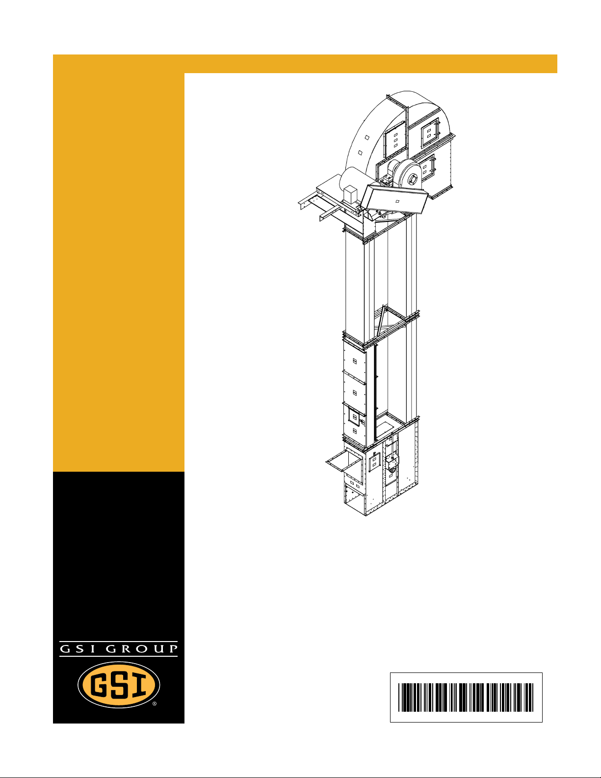
Series II Bucket Elevator
Assembly Manual
PNEG-681
Date: 04-26-12
Page 2

Use of the equipment information page will help you identify the equipment in the case that you need to notify the
company. For this reason, this information should be filled out and kept on record.
Equipment Information
Model Number: ______________________________________________
Serial Number: ______________________________________________
RPM: _____________________________________________________
Head Pulley Diameter: ________________________________________
Discharge Height: ____________________________________________
Horsepower: ________________________________________________
GSI Group
1004 E. Illinois St.
Assumption, IL. 62510
Phone: 1-217-226-4421
Date Purchased: ___________________________________________
Dealer Name and Phone Number: ________________________________
________________________________
________________________________
2 PNEG-681 Series II Bucket Elevator
Page 3

Table of Contents
Contents
Chapter 1 Introduction ..........................................................................................................................................4
General Safety Statements ................................................................................................................... 4
Receiving Inspection . ... ... ...................................................................................................................... 4
Pre-Installation Notifications .................................................................................................................. 4
Chapter 2 Safety .....................................................................................................................................................5
Safety Guidelines .................................................................................................................................. 5
General Safety Statement ..................................................................................................................... 6
Safety Instructions ..................... ... .... .......................................... ... ... ..................................................... 7
Chapter 3 Safety Decals ......................................................................................................................................10
Decal Placement ................................................................................................................................. 12
Chapter 4 Elevator Parts .....................................................................................................................................13
Part Identification ................................................................................................................................ 13
Chapter 5 Bucket Elevator Foundation ..............................................................................................................14
Chapter 6 Boot Section .......................................................................................................................................15
Attaching Boot to Foundation .............................................................................................................. 15
Inspection Sections ................................................ ... .... ... ... .......................................... ... ................... 16
Chapter 7 Trunking ..............................................................................................................................................17
Standard Trunking ............................................................................................................................... 17
Pressure Relief Trunking ..................................................................................................................... 18
Trunking Installation ............................................................................................................................ 19
Chapter 8 Lower Head Section ...........................................................................................................................20
Head Bonnet Section .......................................................................................................................... 20
Chapter 9 Maintaining Plubmness .....................................................................................................................22
Chapter 10 Belting, Splicing and Buckets .........................................................................................................23
Belts ................................... ................ ............. ................ ................ ................ ................................... 23
Splicing .............................................................................................................................................. 23
Buckets .......................... ................................................. ................................................................... 24
Belt Slack Removal ........................................................................................................................... 24
Chapter 11 Drive Motor and Motor Mount .........................................................................................................26
Drive .................................................................................................................................................. 26
Motor Mount Assembly ............................ ... .... ... ... .......................................... ... .... ............................ 26
Slide Base ......................................................................................................................................... 27
Torque Arm ........................ ... ... ... .......................................... .... ... ...................................................... 28
Shaft Mount Reducer ......................................................................................................................... 29
Drive Guard ....................................................................................................................................... 29
Drive Belts ......................................................................................................................................... 33
Chapter 12 Final Checks, Tracking, Start-Up and Maintenance ......................................................................34
General Final Checks ........................................................................................................................ 34
Belt Tracking ...................................................................................................................................... 35
Start-Up ............................................................................................................................................. 35
Maintenance ...................................................................................................................................... 35
Chapter 13 Appendix 1 - Reference Information ...............................................................................................36
Chapter 14 Warranty ............................................................................................................................................37
PNEG-681 Series II Bucket Elevator 3
Page 4

1. Introduction
Thank you for choosing a GSI product. It has been designed to provide excellent performance and service
for many years.
This manual covers general information about installing the GSI Bucket Elevator.
Due to the large variety of equipment features offered, this manual cannot cover every aspect of
installation with this manual. This manual provides suggested and recommended methods for installing
the product. GSI recommends you retain a qualified contractor to provide on-site expertise.
GSI is not responsible for the installation of this product.
General Safety Statements
1. Our primary concern is your safety and the safety of others associated with the use of this product.
All personnel responsible for installing, operating or maintaining this equipment should read and
understand this manual. It is the responsibility of the owner to make this manual available to the
person or persons involved with this equipment.
2. Guards and safety labels have been installed prior to leaving the manufacturing plant. These should
not to be removed, altered or defaced in any way.
3. Modifications to equipment may cause extremely dangerous situations that could result in damage
to the equipment as well as serious injury or death. Never modify the equipment.
4. GSI recommends that you contact the local power company to have a representative survey the
installation to ensure wiring is compatible with their system and adequate power is supplied to
the unit.
Receiving Inspection
1. Carefully inspect the shipment for damage as soon as it is received and verify that the quantity of
parts or packages actually received corresponds to the quantity shown on the packing slip.
2. Report any discrepancies, shortages or damages to the delivering carrier as soon as possible.
3. The manufacturer’s responsibility for damage to the equipment ends when the carrier accepts the
equipment for delivery. Refer to the bill of lading for more detailed information.
4. Save all paperwork and documentation furnished with any of the elevator components.
Pre-Installation Notifications
1. GSI is the manufacturer and vendor of the elevator and is responsible only for the optional
accessories also manufactured by GSI.
2. This installation manual should be used for reference only.
3. The owner/user/installer of this equipment is responsible for consulting and retaining a civil or
structural engineer regarding the design, construction and supervision of the entire installation,
including the elevator foundation and the guying cable and/or bracing system.
4. GSI Bucket Elevators are designed to be vertically self-supporting when erected but must be
supported or guyed against wind loads.
4 PNEG-681 Series II Bucket Elevator
Page 5

2. Safety
DANGER
WARNING
CAUTION
NOTICE
This is the safety alert symbol. It is used to alert you
to potential personal injury hazards. Obey all safety
messages that follow this symbol to avoid possible
injury or death.
WARNING indicates a hazardous situation which, if not
avoided, could result in death or serious injury.
CAUTION, used with the safety alert symbol, indicates a
hazardous situation which, if not avoided, could result in
minor or moderate injury.
NOTICE is used to address practices not related to
personal injury.
DANGER indicates a hazardous situation which, if not
avoided, will result in death or serious injury.
Safety Guidelines
This manual contains information that is important for you, the owner/operator, to know and understand.
This information relates to protecting personal safety and preventing equipment problems. It is the
responsibility of the owner/operator to inform anyone operating or working in the area of this equipment
of these safety guidelines. To help you recognize this information, we use the symbols that are defined
below. Please read the manual and pay attention to these sections. Failure to read this manual and its
safety instructions is a misuse of the equipment and may lead to serious injury or death.
PNEG-681 Series II Bucket Elevator 5
Page 6
2. Safety
This product has sharp edges, which may cause serious injury. To avoid injury, handle
sharp edges with caution and always use proper protective clothing and equipment.
General Safety Statement
Our foremost concern is your safety and the safety of others associated with grain handling equipment.
This manual is to help you understand safe operating procedures and some problems that may be
encountered by the operator and other personnel.
As owner and/or operator, you are responsible to know what requirements, hazards, and precau tions exist
and inform all personnel associated with the equipment or in the area. Safety precautions may be required
from the personnel. Avoid any alterations to the equipment, which may produce a very dangerous
situation, where SERIOUS INJURY or DEATH may occur.
You should consider the location of the bin site relative to power line locations or electrical transmission
equipment. Contact your local power company to review your installation plan or for information
concerning required equipment clearance. Clearance of portable equipment that may be taken to the bin
site should also be reviewed and considered. Any electrical control equipment in contact with the bin
should be properly grounded and installed in accordance with National Electric Code provisions and other
local or national codes.
This product is intended for the use of grain storage only. Any other use is a misuse of the product.
Sidewall bundles or sheets must be stored in a safe manner. The safest method of storing sidewall
bundles is laying horizontally with the arch of the sheet upward, like a dome. Sidewall sheets stored on
edge must be secured so that they cannot fall over and cause injury. Use care when handling and moving
sidewall bundles.
Personnel operating or working around equipment should read this manual. This manual must be
delivered with equipment to its owner. Failure to read this manual and its safety instructions is a
misuse of the equipment.
6 PNEG-681 Series II Bucket Elevator
Page 7

2. Safety
Follow Safety Instructions
Carefully read all safety messages in this manual and
safety signs on your machine. Keep signs in good
condition. Replace missing or damaged safety signs. Be
sure new equipment components and repair parts include
the current safety signs. Replacement safety signs are
available from the manufacturer.
Learn how to operate the machine and how to use controls
properly. Do not let anyone operate without instruction.
Keep your machinery in proper working condition.
Unauthorized modifications to the machine may impair
the function and/or safety and affect machine life.
If you do not understand any part of this manual or need
assistance, contact your dealer.
Read and Understand Manual
Stay Clear of Moving Belt
Entanglement in moving belt can cause serious
injury or death.
Keep all shields and covers in place at all times.
Wear close fitting clothing. Stop and lock out power
source before making adjustments, cleaning, or
maintaining equipment.
Safety Instructions
Our foremost concern is your safety and the safety of others associated with this equipment. We want to
keep you as a customer. This manual is to help you understand safe operating procedures and some
problems that may be encountered by the operator and other personnel.
As owner and/or operator, it is your responsibility to know what requirements, hazards, and precautions
exist, and to inform all personnel associated with the equipment or in the area. Safety precautions may be
required from the personnel. Avoid any alterations to the equipment. Such alterations may produce a very
dangerous situation where SERIOUS INJURY or DEATH may occur.
This equipment shall be installed in accordance with the current installation codes and applicable
regulations, which should be carefully followed in all cases. Authorities having jurisdiction should be
consulted before installations are made.
PNEG-681 Series II Bucket Elevator 7
Page 8
2. Safety
Operate Motor Properly
In an emergency, shut down the power source.
Turn OFF and lock out all power sources before performing
any maintenance.
Do not operate electric motor equipped units until motors are
properly grounded.
Disconnect power on electrical driven units before resetting
motor overloads.
Do not repetitively stop and start the drive in order to free a
plugged condition. Jogging the drive in this manner can damage
the equipment and/or drive components.
Electric Shock Hazard
Practice Safe Maintenance
Understand service procedures before doing work. Keep area
clean and dry.
Never lubricate, service, or adjust machine while it is in operation.
Keep hands, feet, and clothing away from rotating parts.
Keep all parts in good condition and properly installed. Fix
damage immediately . Replace worn or broken p arts. Remove any
built-up grease, oil, and debris.
Maintain Equipment
and Work Area
Remove Paint Before Welding or Heating
Avoid potentially toxic fumes and dust.
Hazardous fumes can be generated when paint is heated by
welding, soldering, or using a torch.
Do all work outside or in a well-ventilated area.
Dispose of paint and solvent properly.
Remove paint before welding or heating:
• If you sand or grind paint, avoid breathing the dust. Wear
an approved respirator.
• If you use solvent or paint stripper, remove stripper with
soap and water before welding. Remove solvent or
stripper containers and other flammable material from
area. Allow fumes to disperse at least 15 minutes
before welding or heating.
Breathing Hazard
8 PNEG-681 Series II Bucket Elevator
Page 9
2. Safety
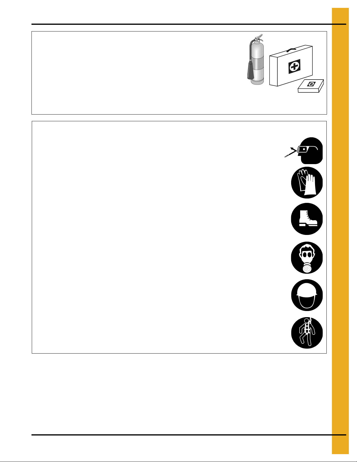
Prepare for Emergencies
Be prepared if fire starts.
Keep a first aid kit and fire extinguisher handy.
Keep emergency numbers for doctors, ambulance service,
hospital, and fire department near your telephone.
Keep Emergency Equipment
Quickly Accessible
Wear Protective Clothing
Wear close-fitting clothing and safety equipment appropriate
to the job.
Remove all jewelry.
Tie long hair up and back.
Wear safety glasses at all times to protect eyes from debris.
Wear gloves to protect your hands from sharp edges on
plastic or steel parts.
Wear steel-toed boots to help protect your feet from falling
debris. Tuck in any loose or dangling shoestrings.
A respirator may be needed to prevent breathing potentially
toxic fumes and dust.
Wear a hard hat to help protect your head.
Wear appropriate fall protection equipment when working at
elevations greater than six feet (6').
Eye Protection
Gloves
Steel-Toed Boots
Respirator
Hard Hat
Fall Protection
PNEG-681 Series II Bucket Elevator 9
Page 10
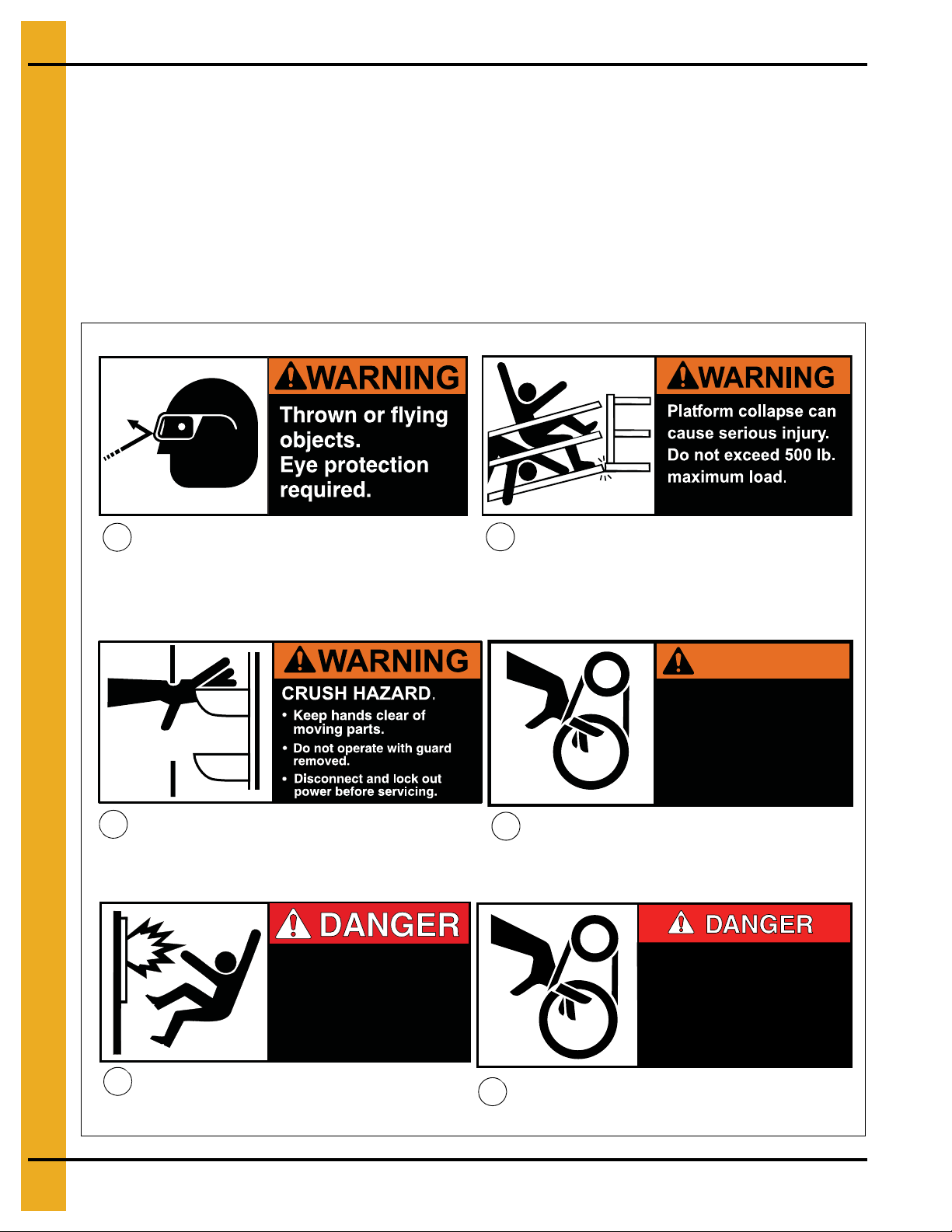
3. Safety Decals
DC-1199
DC-1199
Explosion release will
cause severe injury or
death. Avoid area
around explosion vent
during operation.
DC-1377
SHEAR POINT
Keep hands clear of moving
parts. Do not operate with
guard removed. Disconnect
and lockout power before
servicing.
DC-994
DC-1198
DC-1377
DC-1378
DC-995
DC-994
1
2
4
3
5
6
Safety decals should be read and understood by all people in the grain handling area. Safety decals have
been affixed to the equipment to warn of danger to people and of possible equipment damage. These
decals must not be removed, tampered with, painted over or obscured in any way. If labels are damaged
or become unreadable, replacement labels are available from the manufacturer.
If a decal is damaged or is missing, contact:
GSI Decals
1004 E. Illinois St.
Assumption, IL. 62510
Phone: 1-217-226-4421
A free replacement decal will be sent to you. (Refer to DC number on the decal.)
DC-1198
DC-1378
WARNING
SHEAR POINT
Keep hands clear of moving
parts. Do not operate with
guard removed. Disconnect
and lockout power before
servicing.
DC-995
10 PNEG-681 Series II Bucket Elevator
Page 11
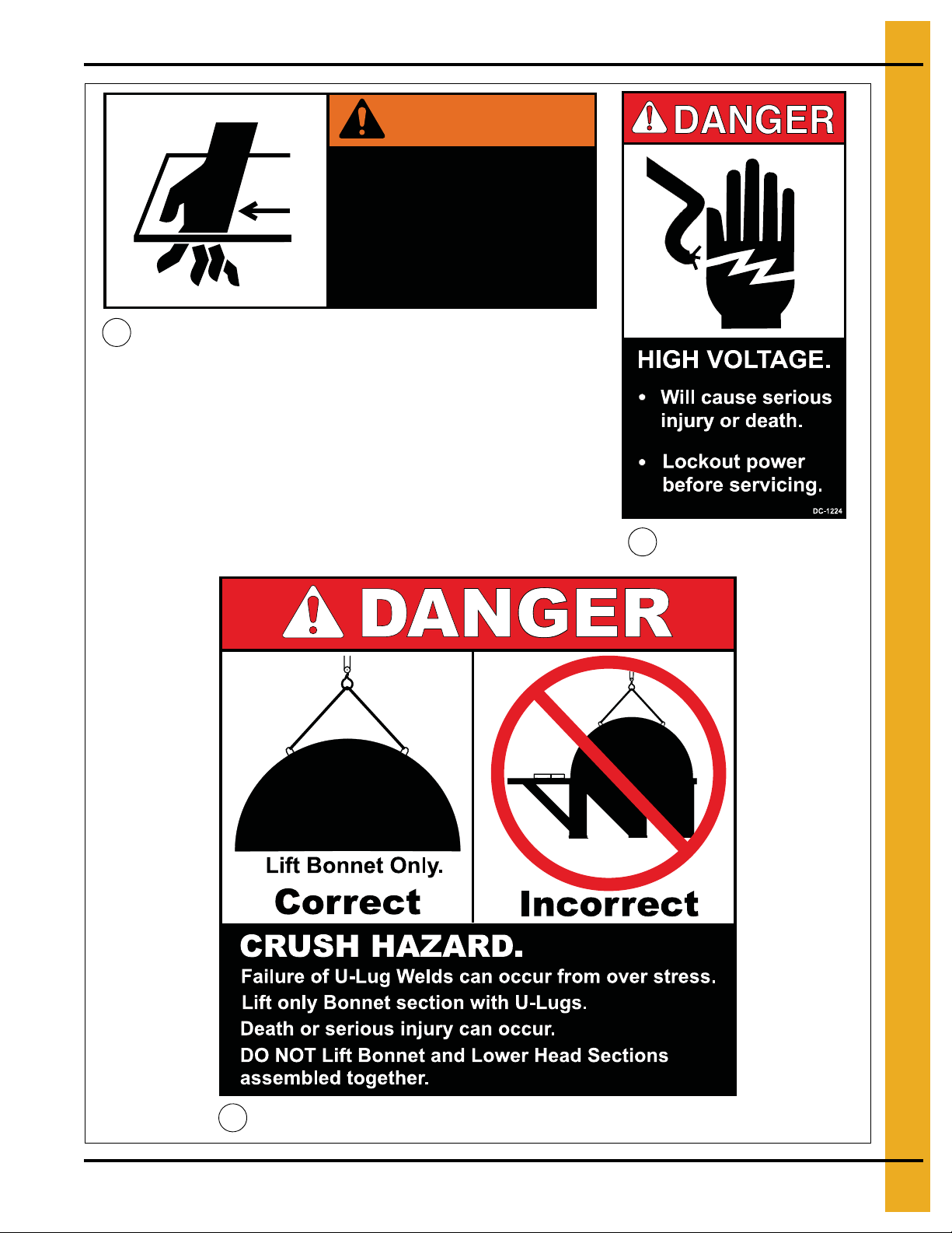
WARNING
Moving side plate.
Auto equipment can
start at any time.
Disconnect and lockout
before servicing.
DC-1248
DC-1248
DC-1224
DC-1601
7
8
9
3. Safety Decals
DC-1601
PNEG-681 Series II Bucket Elevator 11
Page 12
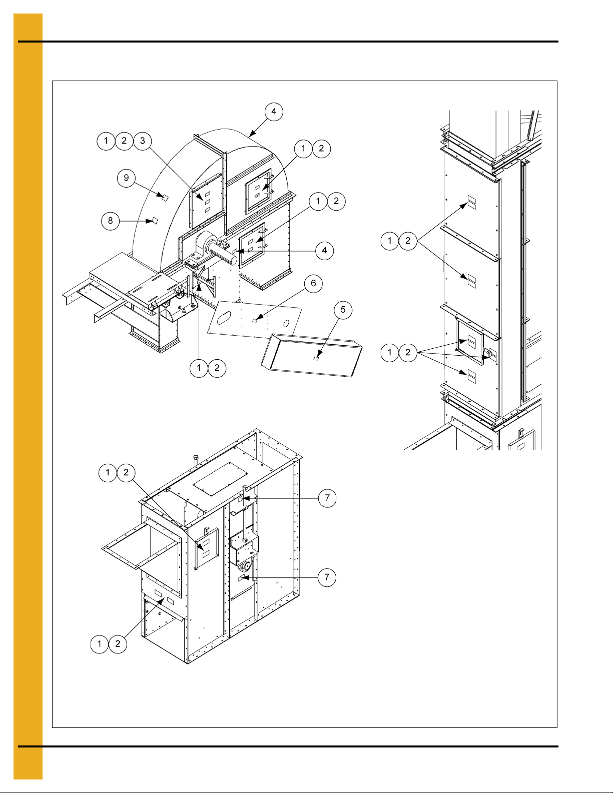
3. Safety Decals
Head section
Inspection trunking
Boot section
Decal numbers
1. DC-1198
2. DC-1199
3. DC-1377
4. DC-1378
5. DC-995
6. DC-994
7. DC-1248
8. DC-1224
9. DC-1601
Decal Placement
12 PNEG-681 Series II Bucket Elevator
Page 13

Part Identification
4. Elevator Parts
Figure 4A
Ref # Description
1 Bonnet
2 Pressure Relief Panel (One Each Side)
3 Head Pulley
4 Lower Head Section
5 Inspection Door
6 Up-Leg Trunking
7 Down-Leg Trunking
8Belt
9 Buckets
10 Tie Angles
11 Inspection Section
12 Inspection Door
13 Boot Section
14 Upside Hopper (Downside Hopper Optional)
PNEG-681 Series II Bucket Elevator 13
Page 14

5. Bucket Elevator Foundation
1. The bucket elevator foundation must be designed by a qualified civil engineer and installed by a
qualified contractor.
2. Always consider the additional weight of live loads, dead loads, wind loads and soil bearing loads.
3. Always provide for proper moisture run-off on the top of the foundation.
14 PNEG-681 Series II Bucket Elevator
Page 15

6. Boot Section
Boot sections are pre-assembled at the factory. Boot inlet hoppers are typically shipped separately.
1. Before installing boot on foundation, examine boot for damage or loose hardware. Do not attempt to
install if parts are damaged.
2. Proper position of boot is critical for successful installation. Boot inlet section can be installed as an
up-leg or a down-leg inlet.
3. Identify the up and down side of boot. (See Figure 6A.)
NOTE: The up-leg inlet position is approximately six inches (6") higher than the down-leg side.
Figure 6A Boot Section
Attaching Boot to Foundation
1. Remove the nuts and inlet blank plates to attach boot inlet hopper.
2. Anchor and level boot. Boot must be level and plumb. There are a variety of ways to accomplish this.
GSI recommends that you shim to the perimeter, secure with hold-downs and grout the base.
3. Set boot in place.
4. Level in all directions prior to anchoring.
5. Use anchor bolts and mounting brackets (not supplied) to secure boot to foundation.
6. Check boot levelness and plumbness periodically throughout the installation process to ensure
proper elevator erection.
PNEG-681 Series II Bucket Elevator 15
Page 16

6. Boot Section
Inspection Sections
The inspection section of the GSI Bucket Elevator has been designed for easy installation
and maintenance.
1. The removable panels can be installed in any order, to allow for the installation of inspection doors
at any preferred locations.
NOTE: Typical installations often place the inspection section directly above the boot on the up-leg side
as the first trunking section.
NOTE: Installation will vary and depend on the configuration and application.
NOTE: Along with the inspection section, you will receive installation hardware and two (2) tie angles.
Units containing 42" diameter pulleys and larger, will include a cross tie on the le gs, which will be
included. (See Figure 6B below and Figure 7A on Page 17.)
Figure 6B Inspection Section
16 PNEG-681 Series II Bucket Elevator
Page 17

7. Trunking
Standard Trunking
Standard trunking sections may be fabricated from painted or galvanized steel.
IMPORTANT: Galvanized steel trunking MUST have the riveted (huck bolted) seams located to the inside,
facing each other on the up-leg and the down-leg. (See Figure 7B.)
NOTE: Trunking sections come complete with appropriate hardware and two (2) tie angles. Units
containing 42" diameter or larger pulleys have a cross tie angle included for additional support.
Figure 7A Painted Trunking
PNEG-681 Series II Bucket Elevator 17
Figure 7B Galvanized Trunking
Page 18

7. Trunking
WARNING
Remove all shipping bolts in the pressure relief panels prior to operating any
bucket elevator.
Pressure Relief Trunking
Pressure relief trunking is standard trunking that has been modified to include two (2) panels specifically
designed for pressure relief.
NOTE: This unit requires special attention to the re lief pan el. This a rea must b e inspected for damage to
the panel, frame and particularly the hardware. DO NOT INSTALL TRUNKING IF THERE IS ANY
APPARENT DAMAGE OR DEFECT.
1. These panels will be located on the short sides of the trunking directly opposite of each other and
centered on ten foot (10') sections of trunking.
2. Two (2) tie angles are included with the mounting hardware.
3. Systems utilizing 42" diameter and larger pulleys require the installation of a cross tie located on
the legs. (See Figure 7C.)
Figure 7C Pressure Relief Trunking
18 PNEG-681 Series II Bucket Elevator
Page 19

7. Trunking
CAUTION
NEVER drill out attachment holes for easier installation of the 1/2" diameter bolts.
If bolts are hindered going through hole, thread bolts through to reduce chances
of damaging threads.
Trunking Installation
Prior to any trunking installation, inspect for damage to equipment. Immediately repair or replace
defective item(s).
NOTE: Always assemble trunking sections on a level surface.
1. Section together to make double trunking.
2. Attach tie angle to single trunking as shown in Figure 7D. (If 42" diameter or larger install cross
tie angle.)
3. Multiple sections can be ground assembled.
4. Make sure sections are assembled straight, without twist.
5. Caulk all mating companion angle surfaces to ensure water and dust resistance.
NOTE: Do NOT assemble more than thirty (30) linear feet at any time.
NOTE: It is important to maintain plumb and square trunking in all directions.
• Guy and plumb trunking in all directions after installing each section.
• Check levels through legging installation process.
• Check all connecting hardware is secure after each installation.
NOTE: Attachment bolt holes in the tie a ngles are intentionally tight for the 1/2" diameter bolts. This helps
ensure more precise plumbing of the trunking. Never drill these holes out for easier installation.
Figure 7D Trunking Joint
PNEG-681 Series II Bucket Elevator 19
Page 20

8. Lower Head Section
WARNING
Use bonnet section ‘U-lugs’ to lift ONLY the bonnet section.
WARNING
NEVER lift or lower the bonnet section together with the lower head section.
WARNING
Remove all shipping bolts in the pressure relief panels prior to operating any
bucket elevator
The Bucket Elevator lower head section is primarily assembled at the factory.
1. The installation hardware used to attach the head section to the trunking system is included with
the shipment.
2. The drive is shipped separately from the lower head section.
3. Inspect all parts for damage and to ensure that all hardware is secure prior to proceeding
with installation. (See Figure 8A.)
Head Bonnet Section
The bonnet has been designed in two-piece construction to allow the front (discharg e) side to slide forward
and clamp in place for maintenance to the belt, buckets, pulley, etc.
1. The rear (up-leg) side bonnet includes factory installed pressure relie f panels. Th ese pane ls sho uld
be carefully inspected for damage including screws and washers.
2. Pressure relief vent door should not be altered in any way, except to remove shipping bolts.
3. Motor mount and torque arm must be adjusted to fit the drive package per supplied detail.
4. Hardware used to attach bonnet section to head section is included. (See Figure 8B on Page 21.)
Figure 8A Lower Head Section
20 PNEG-681 Series II Bucket Elevator
Page 21

8. Lower Head Section
DC-1601
Figure 8B Head Bonnet
PNEG-681 Series II Bucket Elevator 21
Page 22

9. Maintaining Plubmness
To ensure proper bucket elevator plumbness, set up two (2) transits, one in each direction. Refer to
Figure 9A for proper tolerance in elevator erection.
Figure 9A Plumbing Tolerance
22 PNEG-681 Series II Bucket Elevator
Page 23

10. Belting, Splicing and Buckets
CAUTION
To prevent the belt from rolling over the top, anchor the upper end securely.
Belts
The belt for the elevator leg has been specifically chosen based on leg height, grain, weight, pulley
diameter, etc.
The belt has been pre-punched to accommodate special buckets with specific spacing.
Installing the belt can be accomplished several different ways. GSI recommends the following:
1. Prior to installing the belt, raise the boot pulley to its upper most point to allow for prope r tension ing.
2. On shorter installations, consider assembling the buckets to the belt before installing the belt. While
this may be less time consuming, the additional weight of the buckets and connecting h ardware may
make the belt more difficult to handle.
3. Feed belt up through the inspection section, over the head pulley, through the down-leg, around the
boot pulley and back up to the splice.
Splicing
After connecting the ends of the belt together, a winching device such as a come-a-long may be required.
GSI recommends splicing the belt by overlapping the belts or by using the bar splice method.
1. When overlap splicing, draw a 5' minimum of the belt coming up from the bottom of the boot over belt
hanging down from head. (See Figure 10A.)
2. An alternative method, the bar splice (not included) is accomplished by turning the ends of the belt
out and affixing the manufactured bar splice components per the manufacturer’s recommendations.
NOTE: Lacing and other specific types of belt splicing are NOT recommended.
Figure 10A Belt Splicing
PNEG-681 Series II Bucket Elevator 23
Page 24

10. Belting, Splicing and Buckets
CAUTION
DO NOT OVER TIGHTEN BOLTS.
CAUTION
Over tightening can lead to breakage.
Buckets
Buckets are attached to belting using elevator bolts pushed through the belting back side, through the
elevator bucket, a flat (fender) washer, a lock washer and a nut.
1. Secure bucket by tightening nut to slightly indent belt back with bolt head.
2. Remember to leave buckets off near the splice area, if installing buckets prior to belt installation.
(See Figure 10A on Page 23.)
Torque requirements are as follows:
• 50" pounds for 1/4" bolts
• 96" pounds for 5/16" bolts
• 180" pounds for 3/8" bolts
3. ALWAYS re-check bolts for correct torque after initial start-up and periodically thereafter.
Belt Slack Removal
Remove any slack in belt after splice connection by lowering boot pulley. It is important that the bo ot pulley
and shaft are checked and maintained to be horizontally level.
Manual Screw Take-Ups
1. Turn the take-up screws on each side of the boot to control the boot pulley position.
2. After each adjustment, ALWAYS lock each take-up screw in position with the lock nut provided.
Gravity Take-Ups
Weight provides the tensioning method for gravity take-up.
NOTE: The weig ht box may not require any additional weight because the weight of the belt, cups, weight
box assembly and boot pulley assembly provide adequate tensioning in the belt to eliminate
slippage at the head pulley.
If additional weight is needed:
1. Add weights (not included) - Do not use increments of greater than 100 pounds.
2. Equally distribute weight from side to side for proper belt tracking.
3. Use the bearing plate adjustment screws to level the boot pulley after any needed weight is added.
24 PNEG-681 Series II Bucket Elevator
Page 25

10. Belting, Splicing and Buckets
4. Loosen the bolts attaching the channels of the weight frame assembly to the bearing plate assembly
before adjusting the bearing screws.
5. After adjustments have been made, re-tighten bolts and snug the bearing plate adjustment screw
lock nuts. (See Figure 10B.)
NOTE: Lowering the bearing plate which the belt is tracking towards on the boot pulley should cause the
belt to track back towards the center of the pulley. Inversely, raising the bearing plate which the
belt is tracking away from will also center the belt.
Figure 10B Take-Ups
PNEG-681 Series II Bucket Elevator 25
Page 26

11. Drive Motor and Motor Mount
Drive
The following assembly instructions are for standard drives as purchased with the elevator. The standard
drive is designed using the Dodge Torque Arm II shaft mount reducer. Details for this application are
included in the appendix section on Page 36.
If you purchased a special drive or drive components from another source, refer to manuals supplied with
these materials.
1. The drive assembly is designed so that the same components fit a left or right hand drive application.
2. If facing the head side, the reducer is between you and the head and the head discharge is on the
right hand side of you, then you have a right hand drive application.
3. If the head discharge is on the left side of you, then you have a left hand drive application.
The Figure 11A below and Figure 11B on Page 27 shown for a right hand application.
Motor Mount Assembly
1. Locate the side of the motor mount which has two (2) decals affixed. (See Figure 11A.) One decal
will have “L.H.” for left hand and one will have “R.H.” for right hand.
2. Place the motor mount with decals facing away from the pulley towards the end of the head
bearing angles.
3. Note the horsepower, class rating and drive application side on the decals. Follow the indication line
next to those numbers to where it points down to the bottom of the motor mount.
4. Slide the motor mount in or out while keeping the decal correctly aligned with the outside toe of the
head bearing angle. (See Figure 11B on Page 27.) This will align the holes in the head bearing angles
to the proper holes in the motor mount assembly.
5. Using the proper hardware, bolt the motor mount down to the head bearing angles. (See Figure 11A.)
Figure 11A Motor Mount Plate
26 PNEG-681 Series II Bucket Elevator
Page 27

11. Drive Motor and Motor Mount
Figure 11B Right Hand Motor Placement Decals
Slide Base
1. Place the motor slide base upon top of the motor mount, with respect to the drive application side.
2. Place the motor onto the motor slide base and position the motor as close as possible toward
the pulley.
NOTE: The slide base will fit in only one set of holes. (See Figure 11C.)
3. Position the tensioning bolt so that tightening pulls the motor AWAY from the pulley.
4. Using the proper hardware, bolt the slide base to the motor mount.
Figure 11C Motor Slide Base
PNEG-681 Series II Bucket Elevator 27
Page 28

11. Drive Motor and Motor Mount
Torque Arm
1. Place the torque arm tube assembly on the head section by sliding the two (2) gussets of the torque
arm assembly between the head bearing angles.
2. Make sure the locking bolts face away from the head section.
3. Attach with the proper hardware. (See Figure 11D and Figure 11E.)
NOTE: On 16" and 24" elevators, the torque arm tube will slide in and out freely with the motor’s torque
causing a positive lock situation.
NOTE: In 30" and large elevators, loosen the three (3) locking bolts and place the torque arm foot
mounting tube in the torque arm assembly such that the foot mounting bracket is to the side in
which the reducer will be mounted. Wait until the reducer is set on the shaft to re-tighten the
locking bolts.
Figure 11D Torque Arm (30"-48")
Figure 11E Torque Arm (16"-24")
28 PNEG-681 Series II Bucket Elevator
Page 29

11. Drive Motor and Motor Mount
CAUTION
NEVER operate the elevator until the gear reducer has been filled with an
approved lubricant as noted in the Torque Arm II appendix section on Page 36.
Shaft Mount Reducer
For reducer assembly, See Page 36 of the Torque Arm II reducer installation appendix which has detailed
instructions for the reducer bushing mounting, cooling fans and backstops.
Once the reducer is assembled:
1. Attach the torque arm turnbuckle assembly to the reducer with proper hardware.
2. Attach the torque arm foot to the foot mounting bracket of the torque arm tube using the
proper hardware.
Drive Guard
1. Attach the drive guard brackets to the motor m ount assembly.
The shorter, broken legs of the brackets will point towards the pulley.
2. Align the guard rear panel of the guard to the brackets. NOTE, in a right hand drive application (as
shown in Figures 11F-11J on Pages 30-32) the flanges of the guard rear panel will face away from
the head section, but in a left hand application, the flanges will point towards the head section.
NOTE: The wider, larger hole in the guard rear panel is intended for the motor output shaft. The
guard rear panel will attach only in one orientation.
3. Once rear panel is bolted on, attach the drive guard struts to the bearing support of the head section
and to the rear panel.
4. Using hardware, bolt the two (2) struts together. All brackets are designed to be adjustable.
5. Place sheaves onto the output shaft of the motor and the input shaft of the reducer.
6. Place belts upon the sheaves and tension as needed.
NOTE: Reducer may need to be rotated, clockwise or counterclockwise, in conjunction with slide
base adjustments, to achieve correct center distance for the drive belts. Move the location of
the reducer torque arm turnbuckle to achieve this rotation, as needed.
NOTE: Belts are designed specifically per application.
7. With drive belts tensioned and reducer rotated (if necessary), tighten all bolts.
(See Figures 11F-11J on Pages 30-32.)
8. Install the safety screen around the motor output shaft by approximating the hole location to the
screen and snipping a clearance hole in screen. (See Figure 11F on Page 30.)
9. Attach using proper hardware.
10. Attach belt guard cover, latch and bolt.
NOTE: Shaft mount reducers are shipped without lubricant.
11. With the reducer in vertical position, fill with lubricant until oil runs out of oil level plug.
NOTE: See the appendix section on Page 36 for volume of oil per reducer size.
PNEG-681 Series II Bucket Elevator 29
Page 30

11. Drive Motor and Motor Mount
Figure 11F Belt Guard
Figure 11G Belt Guard Mounted to Brackets
30 PNEG-681 Series II Bucket Elevator
Page 31

11. Drive Motor and Motor Mount
Figure 11 H Slide Bracket
Figure 11I Brackets - Use for Higher HP Motors
PNEG-681 Series II Bucket Elevator 31
Page 32

11. Drive Motor and Motor Mount
Figure 11J Bra ckets - Use for Higher HP Motors
32 PNEG-681 Series II Bucket Elevator
Page 33

11. Drive Motor and Motor Mount
Drive Belts
Drive belts are designed to fit loosely upon installation.
Use the motor mount adjustable slide base to properly tension belts to acceptable levels.
Proper tension is 1/64" of deflection per, 1" of sheave centers on one side of belt, centered
between sheaves. (See Figure 11K.)
NOTE: Too much tension shortens belt life. Check belt tension frequently during the first 24-48 hours
of operation.
Figure 11K Drive Belt
PNEG-681 Series II Bucket Elevator 33
Page 34

12. Final Checks, Tracking, Start-Up and Maintenance
CAUTION
1. Check clearance at the lap splice.
2. Do a final check of all parts to be sure all hardware is tight and no foreign
objects or tools are left inside elevator.
3. Check all guards, inspection doors and removable plates to be sure they are in
place and secure.
4. Tighten the take-up screws on the boot evenly to tighten the belt on the pulley,
keeping bottom pulley level and work from side to side in small amounts until
belt is tight.
5. Rotate by hand or carefully jog drive to check for proper rotati on, clearance and
operation of entire unit. Make any adjustments necessary.
6. Jog the drive a minimum of one complete revolution of belt. If no problems
exist, carefully run the bucket elevator.
General Final Checks
1. Adjust the throat plate in the head discharge so there is approximately 1/4" clearance between it and
edge of the buckets on the lap splice. (See Figure 12A.)
Figure 12A Throat Plate
34 PNEG-681 Series II Bucket Elevator
Page 35

12. Final Checks, Tracking, Start-Up and Maintenance
Belt Tracking
Tracking of the belt is very important for optimum results.
1. To correct any tracking problems.
• First adjust the boot bearing plates.
• Adjust the take-up screws downward on the side that the belt is tracking toward.
2. If this does not correct the problem or if the belt is tracking properly on the boot pulley but not the
head pulley, further adjustments to the head pulley may be required.
3. The bearing side that the belt is tracking toward may need to be shimmed to compensate.
• Loosen the head bearing bolts that go through the head angle.
• Use the jacking screws to raise the bearing.
• Place a full shim the bearing base.
• Back off the screws.
• Re-tighten the bearing mounting bolts.
NOTE: Use thin shims to make small adjustments until the belt tracks properly.
Start-Up
Once you are sure all installations, safety checks, adjustments and lubrications have been completed:
1. Run the elevator for WITHOUT LOAD an initial break-in period of several hours.
2. Look and listen for any irregularities before running any material through the unit.
3. Re-check all moving parts and adjust as needed.
4. Adjust belt for final tension under load as needed.
Maintenance
Regularly scheduled maintenance helps ensure long life and safe operation of the unit.
1. Routine maintenance checks may include general wear, loose nuts and bolts, electrical wiring,
contacts, switches, misalignment, guy wire inspection, bearing seals and lubrication and oil content
for gearbox.
2. The belt will stretch after installation and may need further adjustment. Expect some stretching during
the first few weeks of operation.
3. On manual take-up boots, belt tension should be maintained by turning the boot take-up screws
slowly and evenly to maintain proper tracking. When the screw adjustment is completely used, the
belt will have to be re-spliced.
NOTE: Good belt tension is critical for proper traction on the pulley and optimum performance.
PNEG-681 Series II Bucket Elevator 35
Page 36

13. Appendix 1 - Reference Information
Information regarding the torque arm, roller bearings and pillow blocks can be downloaded from the
Baldor website.
Go to www.baldor.com/support/product_manuals.asp
Enter the required manual number into the search field. See list below.
MN1601 - Dodge Torque-Arm II Speed Reducer Installation
MN3033 - Dodge S-2000 Spherical Roller Bearings
MN3040 - Dodge TAF Pillow Blocks and S-1 Units
36 PNEG-681 Series II Bucket Elevator
Page 37

14. Warranty
9101239_1_CR_rev7.DOC (revised July 2009)
GSI Group, LLC Limited Warranty
The GSI Group, LLC (“GSI”) warrants products which it manufactures to be free of defects in materials and workmanship
under normal usage and conditions for a period of 12 months after sale to the original end-user or if a foreign sale,
14 months from arrival at port of discharge, whichever is earlier. The end-user’s sole remedy (and GSI’s only obligation)
is to repair or replace, at GSI’s option and expense, products that in GSI’s judgment, contain a material defect in materials
or workmanship. Expenses incurred by or on behalf of the end-user without prior written authorization from the GSI
Warranty Group shall be the sole responsibility of the end-user.
Warranty Extensions:
The Limited Warranty period is extended for the following products:
Product Warranty Period
Performer Series Direct Drive Fan Motor 3 Years
AP Fans and Flooring
Cumberland
Feeding/Watering
Systems
Grain Systems Grain Bin Structural Design 5 Years
Grain Systems
Farm Fans
Zimmerman
All Fiberglass Housings Lifetime
All Fiberglass Propellers Lifetime
Feeder System Pan Assemblies 5 Years **
Feed Tubes (1-3/4" and 2.00") 10 Years *
Centerless Augers 10 Years *
Watering Nipples 10 Years *
Portable and Tower Dryers 2 Years
Portable and Tower Dryer Frames and
Internal Infrastructure †
5 Years
* Warranty prorated from list price:
0 to 3 years - no cost to end-user
3 to 5 years - end-user pays 25%
5 to 7 years - end-user pays 50%
7 to 10 years - end-user pays 75%
** Warranty prorated from list price:
0 to 3 years - no cost to end-user
3 to 5 years - end-user pays 50%
† Motors, burner components
and moving parts not included.
Portable dryer screens included.
Tower dryer screens not included.
GSI further warrants that the portable and tower dryer frame and basket, excluding all auger and auger drive components,
shall be free from defects in materials for a period of time beginning on the twelfth (12
and continuing until the sixtieth (60
th
) month from the date of purchase (extended warranty period). During the extended
th
) month from the date of purchase
warranty period, GSI will replace the frame or basket components that prove to be defective under normal conditions
of use without charge, excluding the labor, transportation, and/or shipping costs incurred in the performance of this
extended warranty.
Conditions and Limitations:
THERE ARE NO WARRANTIES THAT EXTEND BEYOND THE LIMITED WARRANTY DESCRIPTION SET FORTH
ABOVE. SPECIFICALLY, GSI MAKES NO FURTHER WARRANTY OF ANY KIND, EXPRESS OR IMPLIED,
INCLUDING, WITHOUT LIMITATION, WARRANTIES OF MERCHANTABILITY OR FITNESS FOR A PARTICULAR
PURPOSE OR USE IN CONNECTION WITH: (I) PRODUCT MANUFACTURED OR SOLD BY GSI OR (II) ANY ADVICE,
INSTRUCTION, RECOMMENDATION OR SUGGESTION PROVIDED BY AN AGENT, REPRESENTA TIVE OR
EMPLOYEE OF GSI REGARDING OR RELATED TO THE CONFIGURATION, INSTALLATION, LAYOUT, SUITABILITY
FOR A PARTICULAR PURPOSE, OR DESIGN OF SUCH PRODUCTS.
GSI shall not be liable for any direct, indirect, incidental or consequential damages, including, without limitation, loss of
anticipated profits or benefits. The sole and exclusive remedy is set forth in the Limited Warranty, which shall not exceed
the amount paid for the product purchased. This warranty is not transferable and applies only to the original end-user. GSI
shall have no obligation or responsibility for any representations or warranties made by or on behalf of any dealer, agent
or distributor.
GSI assumes no responsibility for claims resulting from construction defects or unauthorized modifications to products
which it manufactured. Modifications to products not specifically delineated in the manual accompanying the equipment at
initial sale will void the Limited Warranty.
This Limited Warranty shall not extend to products or parts which have been damaged by negligent use, misuse, alteration,
accident or which have been improperly/inadequately maintained. This Limited Warranty extends solely to products
manufactured by GSI.
Prior to installation, the end-user has the responsibility to comply with federal, state and local codes which apply to the
location and installation of products manufactured or sold by GSI.
PNEG-681 Series II Bucket Elevator 37
Page 38

This equipment shall be installed in accordance with
the current installation codes and applicable
regulations, which should be carefully followed in
all cases. Authorities having jurisdiction should be
consulted before installations are made.
Copyright © 2012 by GSI Group
Printed in the USA
GSI Group
1004 E. Illinois St.
Assumption, IL 62510-0020
Phone: 1-217-226-4421
Fax: 1-217-226-4420
www.gsiag.com
CN-208241
 Loading...