

Page 1
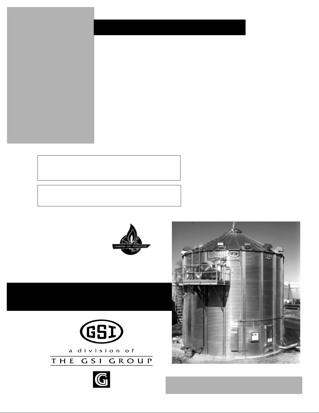
2000 Autoflow
Control Installation
MODEL # 2TF - __ __ - __ __ __
MODEL # 2TFC- __ __ __ __ __
Series 2000
Autoflow
Fan/Heater
Instructions
MODEL # 2TAF - __ __ __ __
Installation
Manual
PNEG-673
1
1
Page 2

2000 Autoflow
This equipment shall be installed in accordance iwth the current INSTALLATION CODES
FOR GAS BURNING APPLICANCES AND EQUIPMENT, CAN1_B149.1 and B149.2, or
applicable provincial regulations which should be carefully followed in all cases. Authorities
having jurisdiction shuld be consulted before installations are made.
2
2
Page 3

2000 Autoflow
Roof W arning, Operation & Safety ................................................................................4
Safety Alert Decals.......................................................................................................5
Safety Precautions........................................................................................................6
Safety Sign-off Sheet...................................................................................................7
Fan/Heater and Control Box Mounting..............................................................................8
Autoflow Control Box Bolt Pattern.................................................................................10
Fill System Control Box Mounting.............................................................................11
Fill System Control Bolt Pattern..................................................................................12
Actuator Control Box Mounting.................................................................................13
Multi-Grain T emperature Sensor Wiring.........................................................................15
Grain T emperature Sensor Mounted to Leveling Band Post........................................16
Close-up of Grain T emperature Sensor Wiring.............................................................17
Plenum T emperature Sensor Installation..........................................................................18
Airswitch Installation.................................................................................................19
W et Supply Rotary Switch..........................................................................................21
Storage Chamber High Limit Rotary Switch Installation...........................................22
Drying Chamber Rotary Switches...............................................................................25
Drying Chamber Low-Level Rotary Switch Installation............................................26
Drying Chamber High-Level Rotary Switch Installation...........................................28
Drying Chamber Overflow Switch Installation.............................................................30
LP Fuel Specifications and Recommendations................................................................32
NG Fuel Specifications and Recommendations...............................................................33
Conduit Runs................................................................................................................34
Electrical Power Supply....................................................................................................35
Figure 12: Ground Rod.....................................................................................................36
Power/Motor Wiring........................................................................................................37
Main Power Schematic.................................................................................................37
Electrical Load Information.............................................................................................38
Wire Size Information................................................................................................39
Fill System Control Box Electrical Load Information.................................................40
Autoflow to Master Fan/Heater Unit Interconnect...........................................................42
Autoflow to Actuator Interconnect.............................................................................43
Autoflow to W et Supply Rotary Switch Interconnect.................................................44
Autoflow to Storage Chamber Rotary Switch Interconnect.......................................45
Autoflow to Drying Chamber Rotary Switches Interconnect..........................................46
Autoflow to Fill System Control Box Interconnect....................................................48
Autoflow to Ground Interconnect.............................................................................. 49
Master to Slave Interconnect......................................................................................50
Slave to Slave Interconnect.........................................................................................51
Battery Hook-Up.........................................................................................................52
Dump Chute Cable Installation...................................................................................53
W arranty .......................................................................................................................55
TABLE OF CONTENTS
3
Page 4
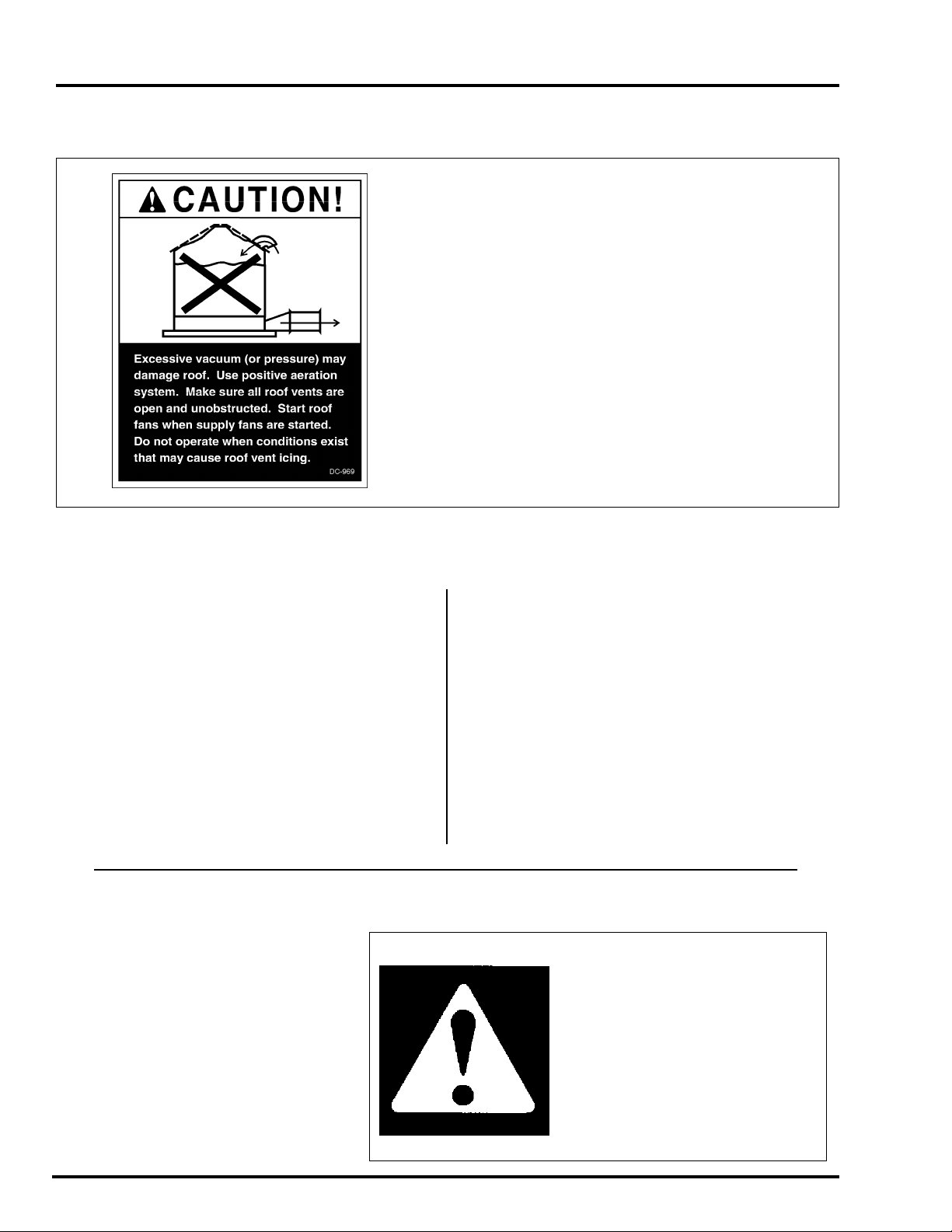
ROOF WARNING, OPERATION & SAFETY
Roof Damage Warning and Disclaimer
GSI DOES NOT WARRANT ANY ROOF DAMAGE
CAUSED BY EXCESSIVE VACUUM OR INTERNAL PRESSURE FROM FANS OR OTHER AIR
MOVING SYSTEMS. ADEQUATE VENTILATION
AND/OR "MAKEUP AIR" DEVICES SHOULD BE
PROVIDED FOR ALL POWERED AIR HANDLING
SYSTEMS. GSI DOES NOT RECOMMEND THE
USE OF DOWNWARD FLOW SYSTEMS (SUCTION). SEVERE ROOF DAMAGE CAN RESULT
FROM ANY BLOCKAGE OF AIR P ASSAGES. RUNNING FANS DURING HIGH HUMIDITY/COLD
WEATHER CONDITIONS CAN CAUSE AIR EXHAUST OR INTAKE PORTS TO FREEZE.
2000 Autoflow
Series 2000 Autoflow Installation & Operating Instructions
Thank you for choosing a Top Dry Series 2000
Autoflow unit. It is designed to give excellent performance and service for many years.
This manual describes the installation for all
standard production T op Dry Series 2000 single fan,
multi-fan and 2000 Series Autoflow units. Different models are available for liquid propane or natural gas fuel supply, with either single phase 230 volt,
or three phase 208, 220, 380, 460 or 575 volt electrical power.
The principal concern of the GSI Group, Inc.
("GSI") is your safety and the safety of others associated with grain handling equipment. This manual
Safety Alert Symbol
The symbol shown is used to call your
attention to instructions concerning
your personal safety. Watch for this
symbol; it points out important safety
precautions. It means "A TTENTION",
"WARNING", "CAUTION", and
"DANGER". Read the message and
be cautious to the possibility of personal injury or death.
is written to help you understand safe operating
procedures, and some of the problems that may be
en-countered by the operator or other
personnel.
As owner and/or operator, it is your responsibility to know what requirements, hazards and precautions exist, and to inform all personnel associated with the equipment, or who are in the fan area.
A void any alterations to the equipment. Such alterations may produce a very dangerous situation,
where serious injury or death may occur.
WARNING! BE ALERT!
Personnel operating or working
around electric fans should read this
manual. This manual must be
delivered with the equipment to its
owner. Failure to read this manual
and its safety instructions is a
misuse of the equipment.
4
Page 5
2000 Autoflow
The GSI Group, Inc. recommends contacting your local
power company, and having a
representative survey your installation so the wiring is compatible with their system, and adequate power is supplied to your
unit.
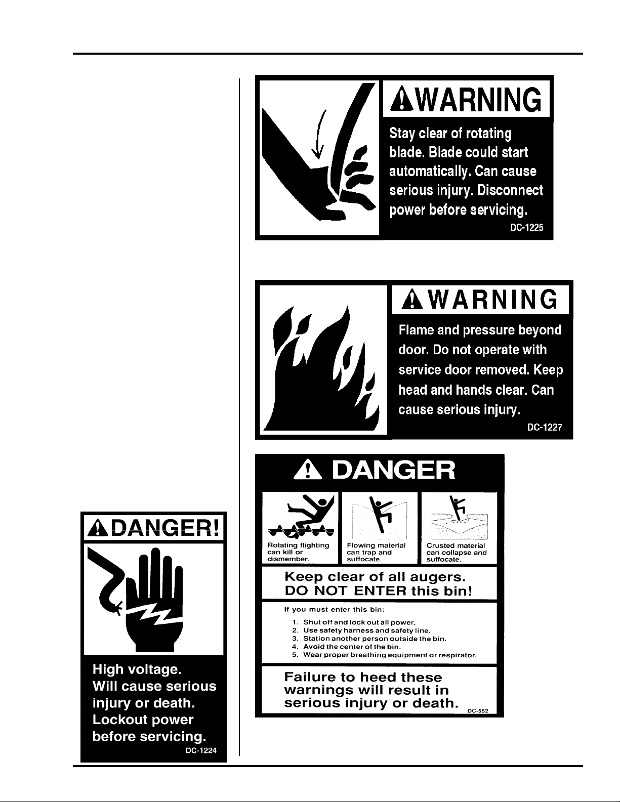
Safety decals should be read
and understood by all people in
the grain handling area. The rotating blade, fire warning decals
and voltage danger decal must be
displayed on the fan can. The
bottom right decal should be
present on the inside bin door
cover of the two ring door, 24"
porthole door cover and the roof
manway cover.
If a decal is damaged or is
missing contact:
The GSI Group, Inc.
1004 E. Illinois St.
Assumption, IL 62510
217-226-4421
A free replacement will be sent to
you.
SAFETY
5
Page 6

SAFETY PRECAUTIONS
READ THESE INSTRUCTIONS
BEFORE OPERATION AND SERVICE
SAVE FOR FUTURE REFERENCE
1. Read and understand the operating manual before trying to operate the
dryer.
2. Power supply should be OFF for service of electrical components. Use
CAUTION in checking voltage or other procedures requiring power to
be ON.
3. Check for gas leaks at all gas pipe connections. If any leaks are detected, do not operate the dryer. Shut down and repair before further
operation.
4. Never attempt to operate the dryer by jumping or otherwise bypassing
any safety devices on the unit.
5. Set pressure regulator to avoid excessive gas pressure applied to burner
during ignition and when burner is in operation. Do not exceed maximum recommended drying temperature.
6. Keep the dryer clean. Do not allow fine material to accumulate in the
plenum or drying chamber.
2000 Autoflow
Use Caution in the
Operation of this
Equipment
The design and manufacture of this
dryer is directed toward operator
safety. However, the very nature of
a grain dryer having a gas burner,
high voltage electrical equipment
and high speed rotating parts, does
present a hazard to personnel, which
can not be completely safeguarded
against, without interfering with efficient operation and reasonable access to components.
Use extreme caution in working
around high speed fans, gas-fired
heaters, augers and auxiliary conveyors, which may start without
warning when the dryer is operating on automatic control.
7. Use CAUTION in working around high speed fans, gas burners, augers
and auxiliary conveyors which START AUTOMATICALLY.
8. Do not operate in any area where combustible material will be drawn into
the fan.
9. Before attempting to remove and reinstall any propellor, make certain to
read the recommended procedure listed within the servicing section of
the manual.
10. Clean grain is easier to dry. Fine material increases resistance to airflow
and requires removal of extra moisture.
Proper Use of Product
This product is intended for the use of drying small grains only.
Any other use is a misuse of the product!
This product has sharp edges! These sharp edges may cause serious
injury. To avoid injury handle sharp edges with caution and use proper
protective clothing and equipment at all times.
Guards are removed for illustrati on purposes only . All guards must be
in place before and during operation.
KEEP THE DRYER CLEAN
DO NOT ALLOW FINE
MATERIAL TO ACCUMULATE
IN THE PLENUM CHAMBER
OR SURROUNDING THE
OUTSIDE OF THE DRYER
Continued safe, dependable operation of automatic equipment depends, to a great degree, upon the
owner. For a safe and dependable
drying system, follow the recommendations within this manual, and
make it a practice to regularly inspect the operation of the unit for
any developing problems or unsafe
conditions.
Take special note of the safety precautions listed above before attempting to operate the dryer.
6
Page 7

2000 Autoflow
SAFETY SIGN-OFF SHEET
Date Employer’s Signature Employee
________________________________________________________________________________________________________________________
_________________________________________________________________________________________________________________________
________________________________________________________________________________________________________________
___________________________________________________________________________________________________________________________
________________________________________________________________________________________________________________________
_____________________________________________________________________________________________________________________________
__________________________________________________________________________________________________________________________
_______________________________________________________________________________________________________________________________
_____________________________________________________________________________________________________________________________
______________________________________________________________________________________________________________________________
___________________________________________________________________________________________________________________________
______________________________________________________________________________________________________________________
_________________________________________________________________________________________________________________________
_____________________________________________________________________________________________________________________
______________________________________________________________________________________________________________________
_________________________________________________________________________________________________________________________
______________________________________________________________________________________________________________________
_______________________________________________________________________________________________________________________
______________________________________________________________________________________________________________________
______________________________________________________________________________________________________________________
_____________________________________________________________________________________________________________________
________________________________________________________________________________________________________________________
______________________________________________________________________________________________________________________
_____________________________________________________________________________________________________________
_______________________________________________________________________________________________________________________
_____________________________________________________________________________________________________________________
___________________________________________________________________________________________________________________
Employees working on or around grain drying equipment
must read this manual and sign-off on this sheet.
7
Page 8
INSTALLATION
2000 Autoflow
Fan and Heater Mounting
1. Inspect the fan platform for proper installation
per instructions in the T op Dry erection manual.
2. Raise the Top Dry fan and heater units to the
platform. Use the table to the right to determine
the height of the platform from the base of the
TopDry unit.
3. Mount the Top Dry fan and heater units to the
bin entrance sheets. Fan legs should set on the
platform.
Autoflow Control Box Mounting
Top Dry Bin Eave Height
Number
of Rings
5
6
7
8
9
10
11
Eave
Height
18-5
22-1
25-9
29-5
33-1
36-9
40-5
Save for Control box mounted on Bin picture
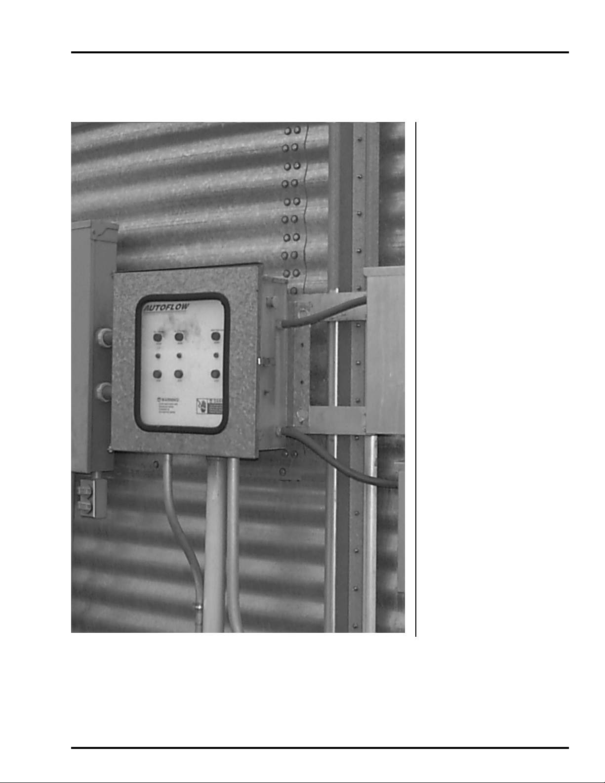
Autoflow Control box mounted on bin.
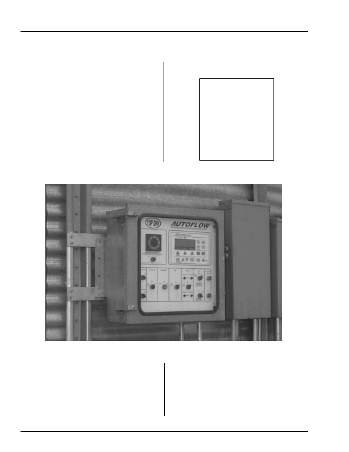
1. The Autoflow Control Box should be
mounted at eye-level. Make sure to mount
the Autoflow control box so that the fan
and heater unit(s) are in view.
2. Keep in mind that wire will be used to inter
connect the Autoflow control Box with the
fan and heater unit(s), Fill System Control
Box, Actuator and all rotary switches.
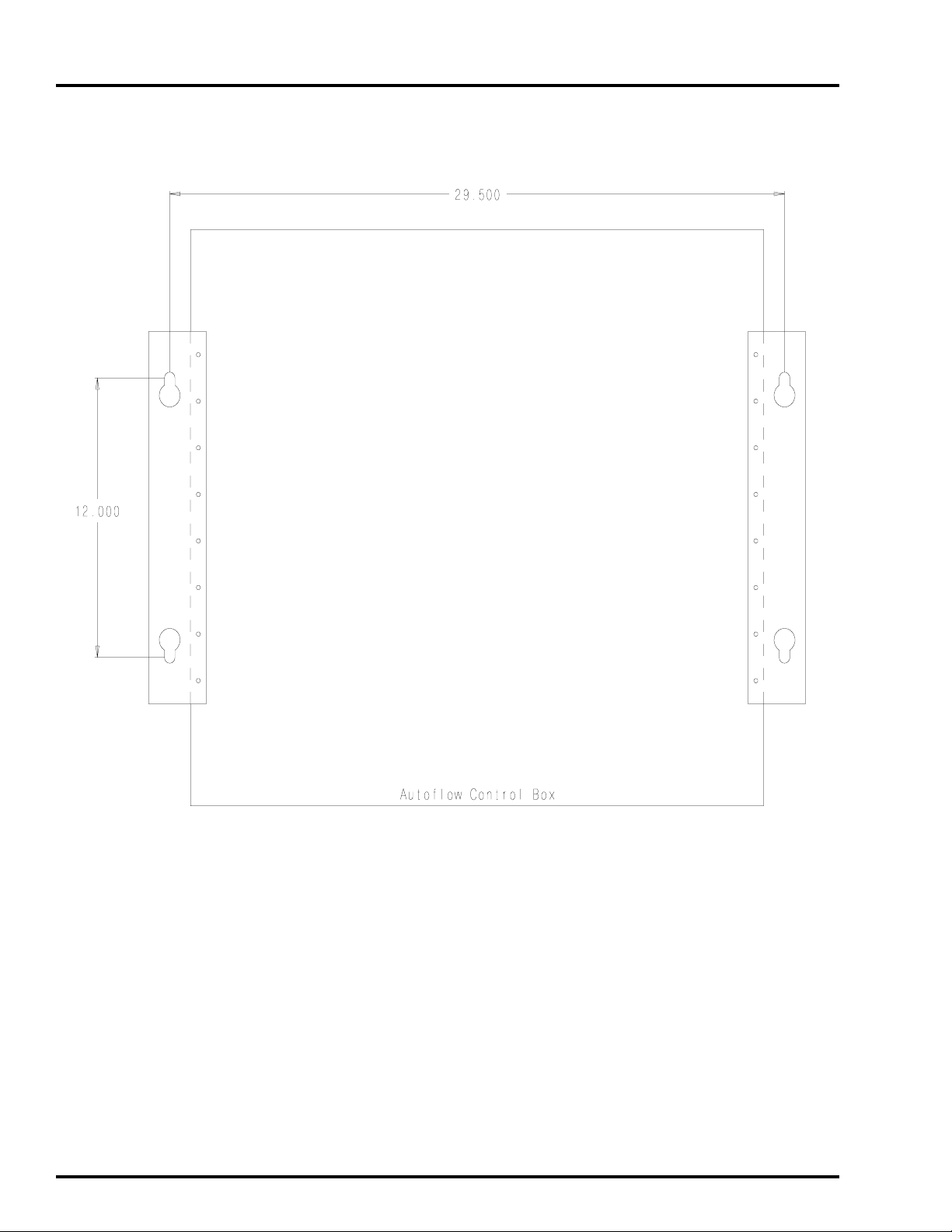
3. Use the hole pattern in Figure 1 to drill holes
for mounting the Autoflow Control Box.
8
Page 9

2000 Autoflow
INSTALLATION
Component Placement
9
Page 10
INSTALLATION
Series 2000 Autoflow Control Box Bolt Pattern
2000 Autoflow
10
Figure 1: Illustration of the bolt pattern for the Autoflow control box.
Page 11
2000 Autoflow
CONTROL BOX MOUNTING
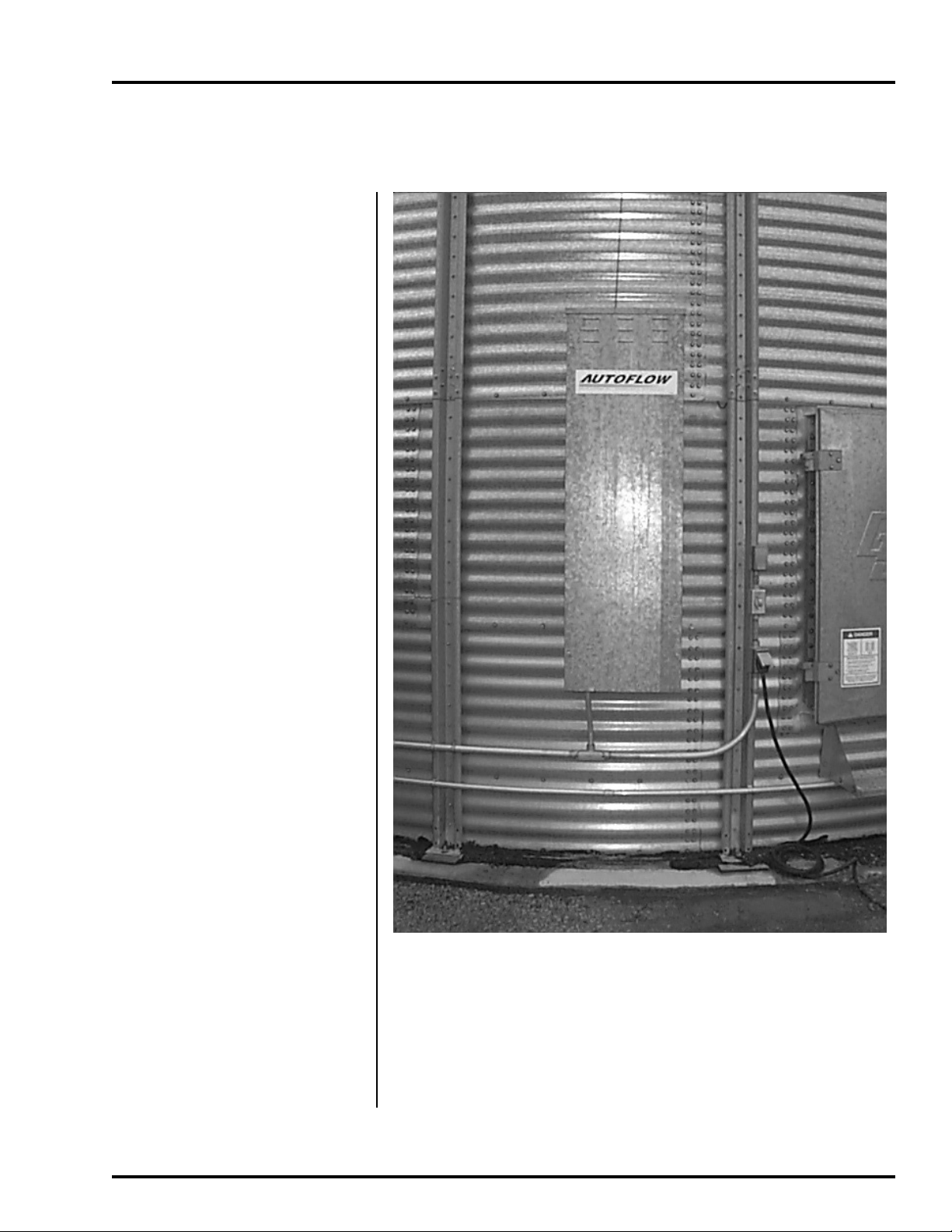
Fill System Control Box Mounting
1) The Fill System
control Box should be
mounted at eye-level.
Make sure to install
the Fill System
Control Box so that
the Fill System(s) and
Aeration fan are in
view.
2) Keep in mind that
wire will be used to
interconnect the Fill
System Control Box
with the Autoflow
Control Box; and,
that power wires will
have to be run from
the entrance panel to
the Fill System
control Box to power
the Fill System and
Aeration fan motors,
which will also run
from the Fill System
Control Box.
Fill System Control Box Mounted to Bin
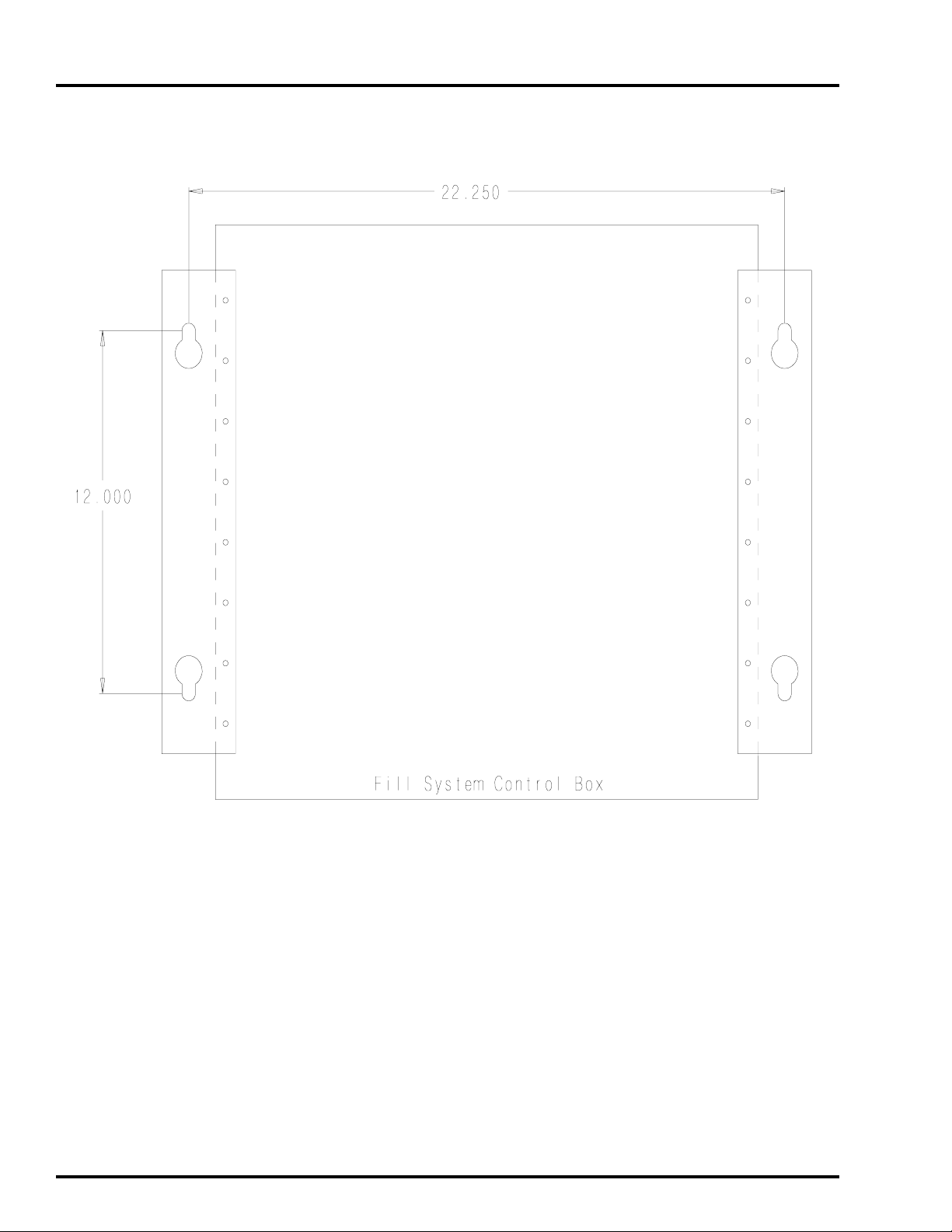
3) Use the pattern in
Figure 2 to drill
holes for the Fill
System Control Box.
11
Page 12
CONTROL BOX MOUNTING
Fill System Control Box Mounting
2000 Autoflow
12
Figure 2: Fill System Control Box Bolt Pattern
Page 13
2000 Autoflow
1) Mark the third sidewall
ring from the ground to
indicate the cable path if
dump chutes and cable are
already installed.
2) Make sure that all dump
chutes and chains are
EVENL Y adjusted so that
when one chute is level
the others are level as
well.
3) Keep in mind that wire
will be used to
interconnect the Actuator
Control Box with the
Autoflow Control Box;
and, that a 110V power
supply will need to run
from the entrance panel to
the Actuator Control Box
to power the 24V DC
battery charger.
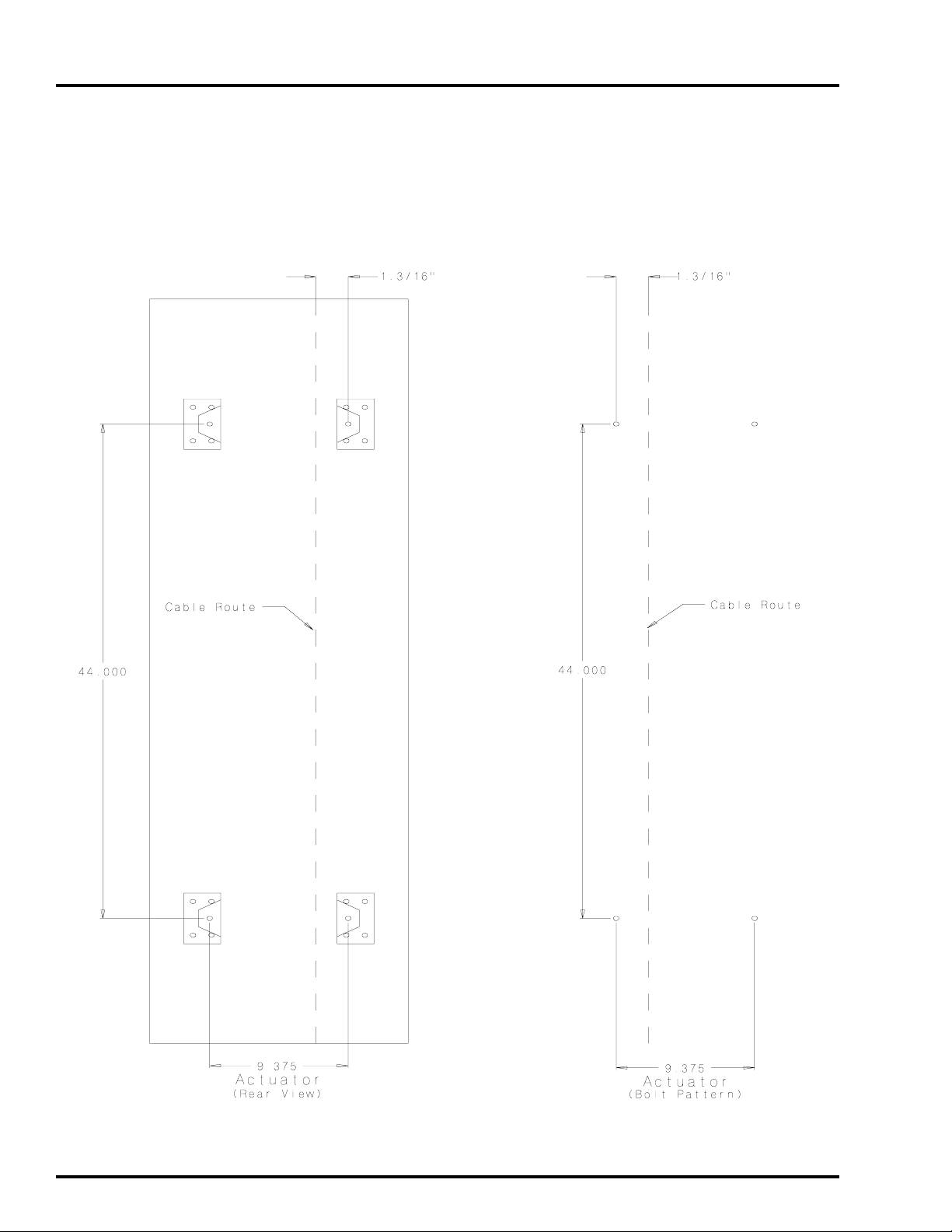
CONTROL BOX MOUNTING
Actuator Control Box Mounting
4) Use the pattern in Figure
3 to drill holes for the
Actuator Control Box.
5) If the horizontal seam
bolts are within 1”
horizontally of the hole
pattern shown, existing
holes may be used to
attach the actuator.
6) Use four 5/16” x 1.1/4”
bin bolts and washers
with bolt heads to the
Actuator Control Box Mounted to Bin
inside of the bin.
7) Do not attach the dump chute cable to the actuator at
this time. The cable should not be installed until after
the actuator unit is completely wired and tested.
13
Page 14
CONTROL BOX MOUNTING
Actuator Control Box Mounting
2000 Autoflow
14
Figure 3: Bolt pattern to drill holes for the Actuator Control Box
Page 15
2000 Autoflow
INSTALLATION
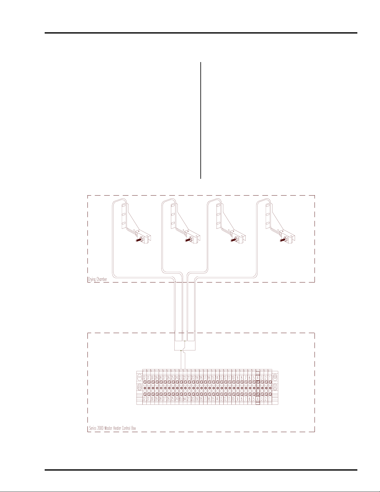
Multi-Grain Temperature Sensor
1. Remove the two wires attached to the grain tem-
perature sensor connected to terminal #22 and
terminal #23 in the fan control box.
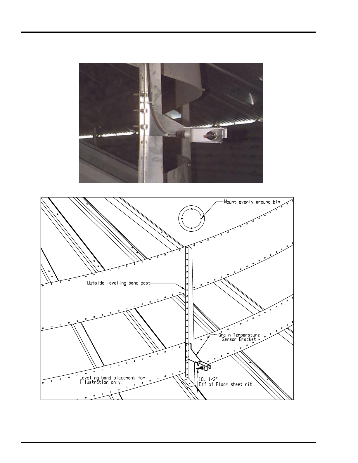
2. Mount the four grain temperature sensor brackets evenly around the drying chamber on out
side leveling band posts (figure 5).
3. With bin bolts mount the bracket so the sensor is
10.1/2” above the floor sheet rib.
4. Wire tie the cords so they feed up the leveling
band post, and across the top leveling band.
5. T ake the cords through the space between the roof
and the top sidewall sheet. There should be enough
on all temperature sensor brackets to exit the dry
ing chamber at the same place.
6. Run the cords back into the fan control box.
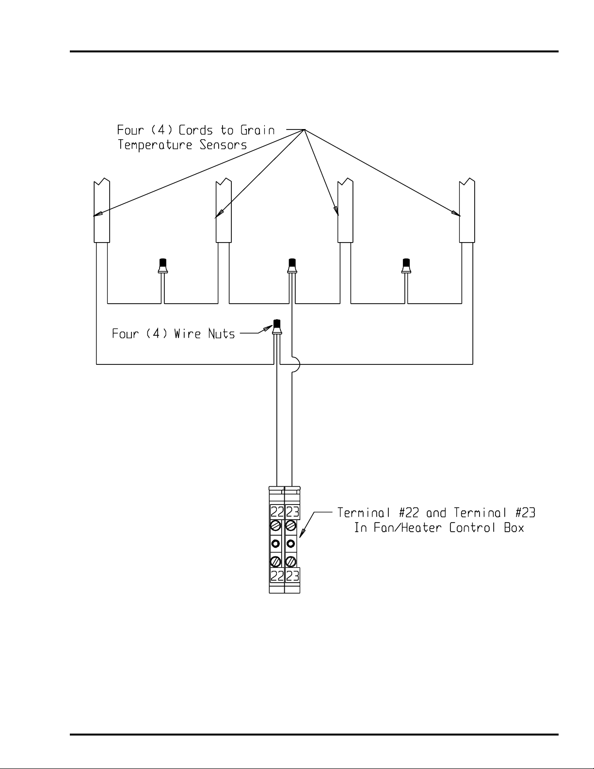
7. Wire the four temperature sensors into terminal
#22 and terminal #23 as detailed in Figure 4 and
the close up detail on page 17.
Figure 4: Illustration of the connection between the master heater control box and multiple sensors in the
drying chamber.
15
Page 16
INSTALLATION
Grain Temperature Sensor Mounted to Leveling Band Post
2000 Autoflow
16
Figure 5: Illustration of grain temperature sensor mounted on outside leveling band post.
Page 17
2000 Autoflow
INSTALLATION
Close-Up Detail of Grain Temperture Sensor Wiring
17
Page 18
INSTALLATION
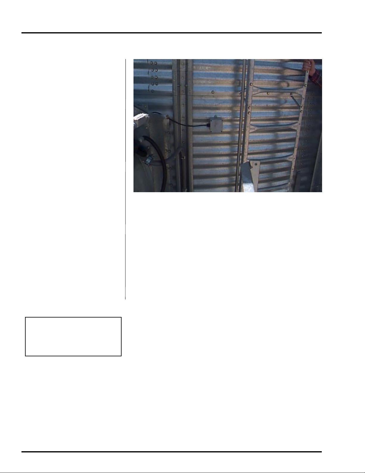
The plenum temperature sensor is
the small grey PVC junction box attached by a cord to the fan/heater
control box on the master fan/heater
unit.
1. On either side of the fan/heater,
drill one 3/4” hole even with the
fan/heater unit in a valley on the
bin sidewall.
2. Insert the probe through the
3/4” hole.
2000 Autoflow
Plenum Temperature Sensor
3. Position the housing so the cord
exits the housing horizontally,
and the tabs fall on the sidewall
peaks.
4. Use two self drilling screws to
mount the housing to the bin
sidewall.
5. Caulk between the housing and
the sidewall to seal.
Important!
If the Top Dry is a two fan unit,
do not mount the plenum temperature sensor between the two
fan/heater units.
Plenum temperature sensor on the bin sidewall.
18
Page 19

2000 Autoflow
1. On either side of the master fan/
heater, drill one 3/4” hole even
with the fan/heater unit in a valley on the bin sidewall.
2. Insert the airswitch probe
through the 3/4” hole.
3. Position the housing so the cord
exits the housing horizontally,
and the vents open downward.
4. Use four self drilling screws to
mount the housing to the bin
sidewall.
INSTALLATION
Airswitch
Airswitch mounted on the bin sidewall.
5. Caulk between the housing and
the sidewall to seal.
19
Page 20

INSTALLATION
2000 Autoflow
Fan/heater unit mounted to the bin, showing the plenum high limit, the airswitch, and cord going through the eave
to the grain temperature sensor brackets.
20
Page 21

2000 Autoflow
INSTALLATION
Wet Supply Rotary Switch
1) Drill a 2” diameter hole through the
hopper bottom.
If a flat bottom bin is being
used for a wet storage tank the
W et Supply Rotary Switch
would be mounted 45 degrees
up the sidewall from the center
of the bin. Example: If the wet
storage bin is 18’ in diameter
then the Wet Supply Rotary
Switch would be mounted 9’
up the sidewall.
2) If the bin is 2.66” corrugation the hole
should be centered on an outside hill.
3) If the bin is 4.00” corrugation the hole
should be centered on an outside
valley .
4) Use the mounting plate as a pattern
and drill four 3/8” holes through the
sidewall at the swich location so the
place can be bolted to the bin.
5) Add foam weather strip around the top
and side of the mounting plate.
6) Caulk the underside of the mounting
plate, on all sides of the 2” hole, and
where the plate meets the bin.
7) Bolt the mounting plate to the
sidewall.
8) Attach the flex coupling to the rotary
switch power pack using a roll pin.
9) Attach the 1-vane paddle to the flex
coupling as shown in figure 6.
10) Apply teflon tape or pipe sealant (not
included) to the rotary switch power
pak threads and thread the rotary
switch power pack into the mounting
plate coupling.
11) Make sure that the conduit hole is
facing down or is horizontal.
Wet Supply Rotary Switch Mounted on Wet Supply Tank
21
Page 22

INSTALLATION
2000 Autoflow
22
Figure 6
Page 23

2000 Autoflow
INSTALLATION
Storage Chamber High Limit Rotary Switch Installation
1) Drill a 2” diameter hole through the
sidewall 3’ below the fan/heater .
2) If the bin is 2.66” corrugation the hole
should be centered on an outside hill.
3) If the bin is 4.00” corrugation the hole
should be centered on an outside
valley.
4) Use the mounting plate as a pattern
and drill four 3/8” holes through the
sidewall at the switch location so the
plate can be bolted to the bin.
5) Add foam weather strip around the top
and side of the mounting plate.
6) Caulk the underside of the mounting
plate, on all sides of the 2” hole, and
where the plate meets the bin.
7) Bolt the mounting plate to the
sidewall.
8) Attach the flex coupling to the rotary
switch power pack using a roll pin.
9) Attach the 1-vane paddle to the flex
coupling as shown in figure 7.
10) Apply teflon tape or pipe sealant (not
included) to the rotary switch power
pak threads and thread the rotary
switch power pack into the mounting
plate coupling.
11) Make sure that the conduit hole is
facing down or is horizontal.
Storage chamber rotary switch.
23
Page 24

INSTALLATION
2000 Autoflow
24
Figure 7
Page 25

2000 Autoflow
INSTALLATION
The three (3) Drying Chamber Rotary
Switches are used by the series 2000 Autoflow to
monitor the location of grain in the Drying Chamber.
The rotary switch with the shortest shaft extension
is the Drying Chamber Overflow Rotary Switch. It
is used as a safety in the event the Chamber High
Level Rotary Switch fails. The rotary switch with
the longest extension is the Drying Chamber Low
Level Rotary Switch. It is used to inform the
computer when the peak has been covered with grain
so the drying process can begin; and, will shut down
if the drying chamber empties unexpectedly. The
third rotary switch is the Drying Chamber High
Level Rotary Switch. It is used to inform the dryer
when the drying chamber is full so loading can stop.
When mounting the Drying Chamber
Rotary Switches some foresight is needed. The
Drying Chamber Rotary Switches should be located
in close proximity to one another to lessen the
amount of conduit and wiring required. The rotary
switches should also be mounted so that they are
located in an area of the drying chamber that fills
evenly with the rest of the drying chamber. The
component placement on page 9 shows the
placement of the Drying Chamber Rotary Switches
in relation to the Fill System #1 transport auger/
downspout.
The rotary switches should NOT be located
in a part of the drying chamber that fills unevenly
with the rest of the drying chamber. If the area of
the drying chamber where the rotary switches are
located fills faster that the rest of the drying chamber
the drying chamber will not fill to capacity and
uneven drying will result. If the area of the drying
chamber where the rotary switches are located fills
slower than the rest of the drying chamber an
overflow situation may occur.
It is very critical that the drying chamber
fill evenly and that the grain falls from Fill System
#1 directly onto the perforated cone in the drying
chamber.
Drying Chamber Rotary Switches Mounted in Bin Roof
25
Page 26

INSTALLATION
Drying Chamber Low-Level Rotary Switch Installation
2000 Autoflow
1) Drill a 2” diameter hole through the
roof panel at the location shown in
figure 8.
See component placement on
page 9 for proper placement in
relation to fill auger .
2) Use the mounting plate as a pattern and
drill four 3/8” holes through the roof
panel at the switch location so the plate
can be bolted to the roof.
3) Attach the flex coupling to the rotary
switch power pack using a roll pin.
4) Apply teflon tape or pipe sealant (not
included) to the rotary switch power
pak threads and thread the rotary
switch power pack into the mounting
plate coupling.
5) Make sure that the conduit hole is at
right angles with the roof panel ribs or
facing towards the eave.
6) Caulk the underside of the mounting
plate and on all sides of the 2” hole.
7) Bolt the assembly to the roof panel.
8) Attach the shaft extension according to
figure 9.
9) Apply teflon tape or pipe sealant (not
included) to the shaft guard.
10) Thread to underneath side of mounting
plate.
11) Add the 1/4” drilled coupling to the
shaft extension using the cotter pin.
12) Attach the 1-vane paddle to the flex
coupling as shown in figure 9.
26
Figure 8
Page 27

2000 Autoflow
INSTALLATION
Figure 9
27
Page 28

INSTALLATION
Drying Chamber High-Level Rotary Switch Installation
2000 Autoflow
1) Drill a 2” diameter hole through the
roof panel at the location shown in
figure 8.
See Component placement on
page 9 for proper placement in
relation to fill auger .
2) Use the mounting plate as a pattern
and drill four 3/8” holes through the
roof panel at the switch location so the
plate can be bolted to the roof.
3) Attach the flex coupling to the rotary
switch power pack using a roll pin.
4) Apply teflon tape or pipe sealant (not
included) to the rotary switch power
pak threads and thread the rotary
switch power pack into the mounting
plate coupling.
5) Make sure that the conduit hole is at
right angles with the roof panel ribs or
facing towards the eave.
6) Caulk the underside of the mounting
plate and on all sides of the 2” hole.
7) Bolt the assembly to the roof panel.
8) Attach the shaft extension according
to figure 10.
9) Apply teflon tape or pipe sealant (not
included) to the shaft guard.
10) Thread to underneath side of
mounting plate.
11) Add the 1/4” drilled coupling to the
shaft extension using the cotter pin.
12) Attach the 3-vane paddle to the flex
coupling as shown in figure 10.
28
Figure 8
Page 29

2000 Autoflow
INSTALLATION
Figure 10
29
Page 30

INSTALLATION
Drying Chamber Overflow Rotary Switch Installation
2000 Autoflow
1) Drill a 2” diameter hole through the
roof panel at the location shown in
figure 8.
See Component placement `
on page 9 for proper placement in relation to fill auger.
2) Use the mounting plate as a pattern
and drill four 3/8” holes through the
roof panel at the switch location so
the plate can be bolted to the roof.
3) Attach the flex coupling to the
rotary switch power pack using a
roll pin.
4) Apply teflon tape or pipe sealant (not
included) to the rotary switch power
pak threads and thread the rotary
switch power pack into the mounting
plate coupling.
5) Make sure that the conduit hole is at
right angles with the roof panel ribs or
facing towards the eave.
6) Caulk the underside of the mounting
plate and on all sides of the 2” hole.
7) Bolt the assembly to the roof panel.
8) Attach the 3-vane paddle to the flex
coupling as shown in figure 11.
30
Figure 8
Page 31

2000 Autoflow
INSTALLATION
Figure 11
31
Page 32

INSTALLATION
2000 Autoflow
Liquid Propane (LP)
T op Dry dryers have internal vaporizers, and they are designed to operate on liquid draw from the supply
tank. Avoid using propane supply
tanks that have been used for vapor
draw for long periods of time. When
using liquid draw systems any moisture that may be present in tanks or
lines may freeze when the system is
used in cold weather. To avoid this
situation, purge the system with
methanol. Do not use tanks which
have previously been used for ammonia or fertilizer solutions. These
substances are extremely corrosive
and will damage fuel supply and
burner parts. Because the vaporizer
coil may need to be adjusted during
operation flexible hose suitable for
LPs should be used for the final field
connection.
See the “Fuel Systems and Rec-
ommendations Chart” for liquid propane to determine the correct size
line to run from the tank to the dryer. Have a qualified gas service person inspect the installation to be sure that everything is installed according to local codes and ordinances.
After installation is complete check all connections for leaks with
liquid detergent or comparable. Wear rubber gloves and eye protection.
A void contact with liquid propane. DO NOT USE FLAME FOR LEAK
TESTING.
LP line field connection.
Dryer
Fan Size
36
36
42
42
42
42
32
Dryer
Horsepower
10-12
15
15
20
30
40
Fuel System Specifications and Recommendations
Liquid Propane (LP)
Maximum Heat
Capacity BTU
Per Hour
3.5 million
4.5 million
5.75 million
6.75 million
8.75 million
10.25 million
Maximum Fuel
Flow Gallons
Per Hour
39
50
64
75
97
113
Minimum
Line Size
1/2
1/2
1/2
1/2
1/2
3/4
Orifice
Size
9/32
.265
.344
3/8
.328
29/64
Minimum
Operating
Pressure
1 lb.
1 lb.
1 lb.
1 lb.
1 lb.
1 lb.
Maximum
Operating
Pressure
15 lbs.
15 lbs.
15 lbs.
15 lbs.
15 lbs.
15 lbs.
Page 33

2000 Autoflow
INSTALLATION
Natural Gas (NG)
This dryer is designed to operate
on natural gas. Natural gas units
have a larger orifice to accommodate lower pressures sometimes
found with natural gas and do not
have vaporizer coils like liquid
propane units. A regulated pressure of 10 PSI minimum, 30 PSI
maximum must be provided at the
field connection point on the fan
and heater unit, with gas available
in sufficient volume to maintain
the operating pressure.
See the “Fuel Systems and
Recommendations Chart” for
natural gas to determine the correct size line to run to the dryer.
Have a qualified gas service person inspect the installation to be
sure everything is installed ac-
cording to local codes and ordinances.
After installation is complete check all connections for leaks with
liquid detergent or comparable. Wear rubber gloves and eye protection.
DO NOT USE FLAME FOR LEAK TESTING.
NG line field connection.
Dryer
Fan Size
36
36
42
42
42
42
Fuel System Specifications and Recommendations
Natural Gas (NG)
Dryer
Horsepower
10-12
15
15
20
30
40
Maximum Heat
Capacity BTU
Per Hour
3.5 million
4.5 million
5.75 million
6.75 million
8.75 million
10.25 million
Maximum Fuel
Flow Cubic Ft.
Per Hour
3500
4500
5750
6750
8750
10250
Minimum
Line Size
1.1/2
2
2
2
2
2
Orifice
Size
13/32
1/2
33/64
35/64
19/32
41/64
Minimum
Operating
Pressure
1 lb.
1 lb.
1 lb.
1 lb.
1 lb.
1 lb.
Maximum
Operating
Pressure
7 lbs.
7 lbs.
7 lbs.
7 lbs.
7 lbs.
7 lbs.
33
Page 34

ELECTRICAL POWER SUPPLY
Conduit Runs
2000 Autoflow
Control Wires
Run #1 Autoflow Control Box to Master
Fan/Heater Control Box
Five (5)-Control wires 16ga minimum
(NOTE: A shielded two conductor 16ga cable should
be used for the network connections.)
Run #2 Autoflow Control Box to Actuator
Control Box
Five (5)-Control wires 16ga minimum
Run #3 Autoflow Control Box to Wet
Supply Rotary Switch
Four (4)-Control wires 16ga minimum
Run #4 Autoflow Control Box to Storage
Chamber Rotary Switch
Five (5)-Control wires 16ga minimum
Power/Motor Wires
Run #1 Entrance Panel to Master Fan/
Heater Control Box (for fan
motor)
Run #2 Entrance Panel to Slave Fan/
Heater Control Boxes (if
applicable, for fan motor)
Run #3 Entrance Panel to Fill System
Control Box ( if applicable)
-For Fill System #1 motor starter
-For Fill System #2 motor starter
(if applicable)
-For Aeration fan motor starter
Run #4 Fill System Control Box to Fill
System #1 Motor
Run #5 Autoflow Control Box to Drying
Chamber Rotary Switches
Six (6)-Control wires 16ga minimum
Run #6 Autoflow Control Box to Fill
System Control Box (if applicable)
T en (10)-Control wires 16ga minimum
Run #7 Master Fan/Heater Control Box to
Slave Fan/Heater Control Box
Four (4)-Control wires 16ga minimum
(NOTE: A shielded two conductor 16ga cable should
be used for the network connections.)
Run #8 Slave Fan/Heater #1 Control Box to
Slave Fan/Heater #2 Control Box
Four (4)-Control wires 16ga minimum
(NOTE: A shielded two conductor 16ga cable should
be used for the network connections.)
Run #5 Fill System Control Box to Fill
System #2 Motor ( if applicable)
Run #6 Fill System Control Box to
Aeration Fan Motor
Run #7 Entrance Panel to Actuator
Control Box
-110V AC, 110V N, Ground wire
for battery charger
Grounding
All Control Boxes should be properly
grounded with a ground lug mounted in each control
box.
34
Page 35

2000 Autoflow
Power Supply
An adequate power supply and proper wiring are important factors for maximum performance and long life of
the dryer. Electrical service must be adequate enough to
prevent low voltage damage to motors and control circuits (see Electrical Load Information on page 40). In
220V 1 ph and 220V 3 ph systems a separate neutral
wire is requir ed for the 120V heater circuit, and should
be connected to terminal #1 in the master heater. Do
not run in conduit with motor power lines.
Transformer and Wiring Voltage Drop
It is necessary to know the distance from the unit to the
available transformer, and the horsepower of your fan
unit. Advise the service representative of your local power
supplier that an additional load will be placed on the line.
Each fan motor should be wired through a fused or circuit breaker disconnect switch. Check on KVA rating of
transformers, considering total horsepower load. The
power supply wiring, main switch equipment and transformers must provide adequate motor starting and operating voltage. Voltage drop during motor starting should
not exceed 14% of normal voltage, and after motor is
running at full speed it should be within 8% of normal
voltage. Check Electrical Load Information for HP ratings and maximum amp loads to properly size wire and
fusing elements. Standard electrical safety practices and
codes should be used. (Refer to National Electrical Code
Standard Handbook by National Fire Protection Association).
ELECTRICAL POWER SUPPLY
boards, and the ignition system. The ground rod must
be in accordance with local requirements.
Proper Installation of Ground Rod
It is not recommended that the rod be driven into dry
ground.
Follow these instructions for proper installation:
1. Dig a hole large enough to hold 1 to 2 gallons of
water.
2. Fill hole with water.
3. Insert rod through water and jab it into the ground.
4. Continue jabbing the rod up and down. The
water will work its way down the hole, making it possible to work the rod completely into
the ground. This method of installing the
rod gives a good conductive bond with the
surrounding soil.
5. Connect the bare, copper ground wire to the
rod with the proper ground rod clamp. See
Figure 12.
6. Connect the bare copper ground wire to the fan
control boxes with a grounding lug.
7. Ground wire must
not have any breaks
or splices.
Machine to Earth Grounding
It is very important that a Machine To Ear th Ground
Rod be installed at the fan. This is true even if there is
a ground at the pole 15 feet away. Place the ground
rod that comes standard, within 8 feet of the dryer
and attach it to the dryer control panel with at least a
#6 solid, bare, copper ground wire and the clamp provided. The grounding rod located at the power pole
will not provide adequate grounding for the dryer . The
proper grounding will provide additional safety in case
of any short and will ensure long life of all circuit
Dig a hole large
enough to hold 1
or 2 gallons of
water. Work the
ground rod into
the earth until it
is completely in
the ground.
35
Page 36

12345678901234567890123456789012123456789012345678901234567890121234567
1
7
1
7
1
7
1
7
1
7
1
7
1
7
1
7
1
7
1
7
1
7
1
7
1
7
1
7
1
7
1
7
1
7
1
7
1
7
12345678901234567890123456789012123456789012345678901234567890121234567
ELECTRICAL POWER SUPPLY
2000 Autoflow
234567890123456789012345678901212345678901234567890123456789012123456
234567890123456789012345678901212345678901234567890123456789012123456
234567890123456789012345678901212345678901234567890123456789012123456
234567890123456789012345678901212345678901234567890123456789012123456
234567890123456789012345678901212345678901234567890123456789012123456
234567890123456789012345678901212345678901234567890123456789012123456
234567890123456789012345678901212345678901234567890123456789012123456
234567890123456789012345678901212345678901234567890123456789012123456
234567890123456789012345678901212345678901234567890123456789012123456
234567890123456789012345678901212345678901234567890123456789012123456
234567890123456789012345678901212345678901234567890123456789012123456
234567890123456789012345678901212345678901234567890123456789012123456
234567890123456789012345678901212345678901234567890123456789012123456
234567890123456789012345678901212345678901234567890123456789012123456
234567890123456789012345678901212345678901234567890123456789012123456
234567890123456789012345678901212345678901234567890123456789012123456
234567890123456789012345678901212345678901234567890123456789012123456
234567890123456789012345678901212345678901234567890123456789012123456
234567890123456789012345678901212345678901234567890123456789012123456
Figure 12: The Top Dry and ground rod attachment illustration.
36
Page 37

2000 Autoflow
POWER/MOTOR WIRING
The Following diagram details the configuration
for correct main power installation. Use the diagram
in conjunction with the Electrical Load information and
Wire Size information provided. The diagram details
the correct main power installation for 220V 1 ph, 230V
ph, 460V 3ph, 575V 3ph, and 380V 50hz power
supplies.
On all three phase systems put the leg with the
highest potential difference between that leg and ground
( wild or high voltage leg) on the center terminal (L2)
at the motor starter.
Main Power Schematic
NOTE: Standard electrical safety should be used.
(Refer to the National Electrical Code Standard
Handbook by the National Fire Protection
Association). A qualified electrician should make
all electrical wiring installations. Follow all local
or national electrical safety standards and
ordinances when installing the equipment.
37
Page 38

ELECTRICAL POWER SUPPLY
2000 Autoflow
Electrical Load
Information
The following charts provide information for the electrician wiring the
grain dryer, and are a reference
guide for parts. It is recommended
that you contact your local power
company and have a representatives
survey the installation to see that
your wiring is compatible with their
system and that adequate power is
supplied to your unit. Remember
that the only thing connected to the
recommended service amps should
be your grain dryer. Standard electrical safety should be used. (Refer
to the National Electrical Code
Standard Handbook by the National
Fire Protection Association). A
qualified electrician should make all
electrical wiring installations.
Dryer Fan
Size Voltage Horsepower
220v1ph 10-12 48 75 F614B 80 80
208v3ph 10-12 35 40 C400B 60 60
36" 220v3ph 10-12 33 40 C366B 60 60
380v50hz 10-12 15 30 C180B 30 30
460v3ph 10-12 17 30 C198B 30 30
575v3ph 10-12 15 30 C180B 30 30
220v1ph 10-16 78 90 F914B 100 100
208v3ph 15 44 60 C460B 60 60
36" 220v3ph 15 39 60 C400B 60 60
380v50hz 15 27 30 F772B 60 60
460v3ph 15 20 30 C228B 30 30
575v3ph 15 16 30 C198B 30 30
220v1ph 10-16 78 90 F914B 100 100
208v3ph 15 44 60 C460B 60 60
42" 220v3ph 15 39 60 C400B 60 60
380v50hz 15 27 30 F772B 60 60
460v3ph 15 20 30 C228B 30 30
Full Load
Amps
Motor
Starter
Relay
Heater
Strips
Fuse
(Slow Blow) Breaker
575v3ph 15 16 30 C198B 30 30
208v3ph 20 61 75 F772B 80 80
220v3ph 20 50 60 C500B 80 80
42" 380v50hz 20 32 40 C366B 60 60
460v3ph 20 25 30 C303B 40 40
575v3ph 20 20 30 C228B 40 40
208v3ph 30 80 90 F104C 150 150
220v3ph 30 74 75 F772B 150 150
42" 380v50hz 30 39 40 C440B 80 80
460v3ph 30 37 40 C400B 80 80
575v3ph 30 30 40 C330B 80 80
208v3ph 40 108 120 F118C 200 200
220v3ph 40 102 120 F118C 200 200
42" 380v50hz 40 47 60 C500B 100 100
460v3ph 40 51 60 C550B 100 100
38
575v3ph 40 40 60 C400B 100 100
Page 39

2000 Autoflow
ELECTRICAL POWER SUPPLY
Wire Size Information
Dryer Fan
Size Voltage Horsepower
220v1ph 10-12 6 4 4 2 2 0
208v3ph 10-12 6 4 4 2 3 2
36" 220v3ph 10-12 6 4 4 2 3 2
380v50hz 10-12 10 8 8 6 6 4
460v3ph 10-12 10 8 8 6 6 4
575v3ph 10-12 10 8 8 6 6 4
220v1ph 10-16 4 2 2 0 1 00
208v3ph15644220
36"220v3ph15644232
380v50hz15644232
460v3ph 15 10 8 8 4 6 3
575v3ph 15 10 8 8 6 6 4
220v1ph 10-16 4 2 2 0 1 00
208v3ph15644220
42"220v3ph15644232
Copper
100' Run
Aluminium
100' Run
Copper
200' Run
Aluminium
200' Run
Copper
300' Run
Aluminium
300' Run
380v50hz15644232
460v3ph 15 10 8 8 4 6 3
575v3ph 15 10 8 8 6 6 4
208v3ph204240100
220v3ph20422010
42"380v50hz20644232
460v3ph 20 10 8 6 4 4 2
575v3ph 20 10 8 6 4 4 2
208v3ph3010000000000000
220v3ph30200000000
42"380v50hz30644232
460v3ph30644232
575v3ph30644232
208v3ph 40 1 0 00 000 0000 0000
220v3ph 40 1 0 00 000 0000 0000
42"380v50hz40644220
460v3ph40644220
575v3ph40644220
39
Page 40

ELECTRICAL POWER SUPPLY
Fill System Control Box Electrical Load Information
2000 Autoflow
The following charts provide information for
the electrician wiring the grain dryer, and are a
reference guide for parts. It is recommended
that you contact your local power company and
have a representative survey the installation to
see that your wiring is compatible with their
system and that adequate power is supplied to
your unit. Remember that the only thing
connected to the recommended service amps
should be your grain dryer. Standard electrical
safety should be used. (Refer to the National
Electrical Code Standard handbook by the
National Fire Protection Association.) A
qualified electrician should make all electrical
wiring installations.
Relay
Fill System
HP Voltage
220v1ph 13 30 C137B
Full Load
Amps
Motor
Starter
Heater
Strips
Fill System
HP Voltage
220v1ph 42 60 C366B
10 HP 220v3ph 25 30 C303B
380v50hz 14 30 C180B
460v3ph 12 30 C163B
575v3ph 9 30 C137B
220v1ph 64 75 F658B
15 HP 220v3ph 37 40 C400B
380v50hz 21 30 C273B
460v3ph 18 30 C214B
575v3ph 14 30 C180B
220v3ph 49 60 C500B
20 HP 380v50hz 28 40 C330B
Full Load
Amps
Motor
Starter
Relay
Heater
Strips
3 HP 220v3ph 7 30 C104B
380v50hz 4 30 C630A
460v3ph 4 30 C630A
575v3ph 3 30 C630A
220v1ph 21 30 C228B
5 HP 220v3ph 12 30 C163B
380v50hz 7 30 C955A
460v3ph 6 30 C778A
575v3ph 5 30 C630A
220v1ph 32 40 C303B
7.5 HP 220v3ph 18 30 C228B
380v50hz 11 30 C151B
460v3ph 9 30 C125B
460v3ph 23 30 C303B
575v3ph 19 30 C228B
220v3ph 61 75 F719B
25 HP 380v50hz 35 40 C400B
460v3ph 29 40 C330B
575v3ph 23 30 C273B
220v3ph 73 75 F772B
30 HP 380v50hz 43 60 C440B
460v3ph 35 40 C400B
575v3ph 28 40 C330B
40
575v3ph 7 30 C955B
Page 41

2000 Autoflow
ELECTRICAL POWER SUPPLY
Figure 18
41
Page 42

ELECTRICAL POWER SUPPLY
Autoflow to Master Fan/Heater Unit Interconnect
2000 Autoflow
The Master Fan/Heater Unit is the only fan
and heater in a single fan unit. In two fan units
it is the fan/heater with the airswitch, plenum
temperature sensor, and grain temperature sensor
connected to it. DO NOT run the control wires
for the Master Fan/Heater in the same conduit
as the power wires for the fan motor. To wire
the Master Fan/Heater Unit to the Autoflow
Control Box do the following.
Important!
NOTE: Do NOT use solid wire for
interconnections.
NOTE: A shielded 16 gauge cable is
recommended for use on the network
connection. The network wires for this
configuration are attached to terminals number
4 and 5. Ground each end of the shielded cable
to the housing. A shielded 16 gauge 2 wire cable
can be purchased from GSI. Part # WR-16 /
2S.
1) Run five (5) control wires from the
Autoflow Control Box to the Master
Fan/Heater Unit.
2) Connect the wires as shown in figure 19.
42
Figure 19
Page 43

2000 Autoflow
ELECTRICAL POWER SUPPLY
Autoflow to Actuator Interconnect
The Actuator Control Box houses the 24V
DC linear actuator, two (2) 12V DC Batteries,
and a 24V DC battery charger. The linear
actuator raises and lowers the dump chutes to
unload grain automatically from the drying
chamber to the storage chamber. The two (2)
12V DC batteries act as a backup to prevent wet
grain from dumping into the storage chamber
during a power outage. The 24V DC battery
charger provides a continuous recharge to the
batteries.
To wire the Actuator Control Box to the
Autoflow Control Box do the following.
1) Run five (5) control wires from the
Autoflow Control Box to the Actuator
Control Box.
2) Run three (3) power wires from the
Entrance Panel to the Actuator Control
Box.
3) Connect the wires as shown in figure
20.
Figure 20
43
Page 44

ELECTRICAL POWER SUPPLY
Autoflow to Wet Supply Rotary Switch Interconnect
2000 Autoflow
The 110V AC rotary switch located in the
wet storage tank is used to inform the computer
on the availability of wet grain. The W et Supply
Rotary Switch use 110V AC to power the motor
and 12V DC + to switch a signal back to the
computer.
To wire the Wet Supply Rotary Switch to
the Autoflow Control Box do the following:
1) Run Four (4) control wires from the
Autoflow Control Box to the Wet
Supply Rotary Switch.
2) Connect the wires as shown in figure 21.
44
Figure 21
Page 45

2000 Autoflow
Autoflow to Storage Chamber Rotary Switch Inerconnect
ELECTRICAL POWER SUPPLY
The 110V AC Rotary switch located in the
storage tank is used to inform the computer on
the availability of wet grain. The Storage
Chamber Rotary Switch is mounted three (3)
feet below the fan/heater unit(s). The Storage
Chamber Rotary Switch use 110V AC to power
the motor and 12V DC + to switch a signal back
to the computer.
T o wire the Storage Chamber Rotary Switch
to the Autoflow Control Box do the following:
1) Run five (5) control wires from the
Autoflow Control Box to the Storage
Chamber Rotary Switch.
2) Connect the wires as shown in figure 22.
Figure 22
45
Page 46

ELECTRIAL POWER SUPPLY
Autoflow to Drying Chamber Rotary Switches Interconnect
2000 Autoflow
The three (3) 110V AC rotary switches
located in the drying chamber are used to inform
the computer on the location of grain in the
drying chamber. The rotary switch with the
shortest extension is the Drying Chamber
Overflow Rotary Switch. It is used as a safety
in the event the Chamber High Level Rotary
Switch fails. The rotary switch with the longest
extension is the Drying Chamber Low Level
Rotary Switch. It is used to inform the computer
when the peak has been covered with grain so
the drying process can begin; and, will shut the
dryer down if the drying chamber empties
unexpectedlly. The third rotary switch is the
Drying Chamber High Level Rotary Switch. It
is used to inform the dryer when the drying
chamber is full. The Drying Chamber Rotary
Switches us 110V AC to power the motor and
12V DC+ to switch a signal back to the
computer. The 1 10V AC, 1 10V N, and the 12V
DC+ wires can be jumped from rotary switch to
rotary switch to lessen the wires needed.
To wire the Drying Chamber Rotary
Switches to the Autoflow Control Box do the
following:
1) Run six (6) control wires from the
Autoflow Control Box to the Drying
Chamber Rotary Switches.
2) Connect the wires as shown in figure 23.
46
Page 47

2000 Autoflow
ELECTRIAL POWER SUPPLY
Figure 23
47
Page 48

ELECTRICAL POWER SUPPLY
Autoflow to Fill System Control Box Interconnect
2000 Autoflow
The Fill System Control Box houses the
starter (s) for the fill system(s) that load grain
into the Top Dry Autoflow Unit and for the
aeration fan. DO NOT run the control wires for
the Fill System Control Box in the same conduit
used for the power wires for the fill system and
aeration fan motors. To wire the Fill System
Control to the Autoflow Control Box do the
following.
1) Run ten (10) control wires from the
Autoflow Control Box to the Fill System
Control Box.
2) Connect the wires as shown in figure 24.
48
Figure 24
Page 49

2000 Autoflow
ELECTRICAL POWER SUPPLY
Autoflow to Ground Interconnect
Figure 25
49
Page 50

ELECTRICAL POWER SUPPLY
Master to Slave Interconnect
2000 Autoflow
A slave fan/heater unit can be added to operate in unison with the master fan/heater unit.
The interconnect between the master and slave
fan/heater units remains the same regardless
of the type or presence of a control center. To
wire a slave fan/heater unit to a master fan/
heater unit do the following:
NOTE: Do NOT use solid wire for interconnection.
1. Run four (4) 16ga MTW type wires from
the master fan/heater unit to the slave fan/
heater unit.
2. Connect the wires as shown in figure #26.
NOTE: A shielded 16 gauge cable is recommended for use on the network connections.
The network connections for this configuration are attached to terminals number 8 and 9
in the master unit and terminals number 3 and
4 in the slave unit. Ground each end of the
shielded cable to the housing. A shielded 16
gauge 2 wire cable can be purchased from GSI.
Part # WR-16 / 2S.
50
Figure 26: Wiring for a slave fan/heater unit to a master fan/heater unit.
Page 51

2000 Autoflow
ELECTRICAL POWER SUPPLY
Slave to Slave Interconnect
A second slave fan/heater unit can be added to
operate in unison with the master fan/heater unit
and another slave fan/heater unit. This would create a three fan unit. The interconnect between
the first slave fan/heater unit and the second slave
fan/heater unit remains the same regardless of
the type or presence of a control center. To wire
a second slave fan/heater unit to another slave
fan/heater unit do the following:
NOTE: Do NOT use solid wire for interconnection.
1. Run four (4) 16ga MTW type wires
from the first slave fan/heater unit to
the second slave fan/heater unit.
2. Connect the wires as shown in figure
#27.
NOTE: A shielded 16 gauge cable is recommended for use on the network connections. The
network connections for this configuration are
attached to terminals number 7 and 8 in slave #1
and terminals number 3 and 4 in slave #2.
Ground each end of the shielded cable to the
housing. A shielded 16 gauge 2 wire cable can
be purchased from GSI. Part #WR-16 / 2S
Figure 27: Wiring for a second slave fan/heater unit to another slave fan/heater unit.
51
Page 52

ELECTRICAL POWER SUPPLY
Battery Hook-Up
2000 Autoflow
Two (2) lawn and garden type 12V DC
Batteries are required for proper operation of the
Actuator Control Box. The two (2) 12V DC
batteries are wired in series to provide the 24V
DC linear actuator with the voltage required to
operate. The two (2) 12V DC batteries should
be mounted on the shelves provided in the
Actuator Control Box.
To wire the two (2) 12V DC batteries to
the 24V DC battery charger do the following:
1) Mount the two (2) 12V DC batteries in
the Actuator Control Box on the proper
shelves.
2) Install a jumper from the negative
terminal on one battery to the positive
terminal on the other battery.
3) Attach the red wire coming from the
fuse block and the positive lead on
the 24V DC battery charger to the open
positive terminal on one battery .
4) Attach the black wire coming from the
fuse block; and the negative lead on
the 24V DC battery charger to the
open negative terminal on the other
battery.
5) Use Figure 28 to guide installation.
52
Figure 28
Page 53

2000 Autoflow
ELECTRICAL POWER SUPPLY
Dump Chute Cable Installation
After complete installation of the Autoflow
Unit the cable should be hooked up to the linear
actuator in the Actuator Control Box. To test
the linear actuator and install the cable do the
following:
1) Turn all switches on the Autoflow
control front panel to the “off”
position.
2) Make sure the Emergency Stop
switches on all the control boxes are
pulled out.
3) Turn the Control Power switch to the
“on” position.
4) The display should read “stopped” at
the bottom.
5) While watching the linear actuator turn
the Dump switch to the “manual open”
position.
7) Place the Dump switch in the “auto”
position and press the Stop switch.
8) The linear actuator should retract and
stop.
9) Place the Control Power switch in the
“off” position and push the Emergency
stop switch in on the Autoflow and
Actuator Control Boxes.
10) Route the cable as shown in figure 29.
11) Make sure that all dump chutes are
approximately 5 degrees below level
when in the closed position.
12) Double check all dump chutes to make
sure that they are all adjusted the same
when in the closed position. The
Autoflow Unit will not operate
properly if the dump chutes are
adjusted unevenly .
6) The Linear actuator should extend
down 16”.
53
Page 54

ELECTRICAL POWER SUPPLY
2000 Autoflow
54
Figure 29
Page 55

2000 Autoflow
<cr>
WARRANTY
THE GSI GROUP, INC. ("GSI") WARRANTS ALL PRODUCTS MANUFACTURED BY GSI
TO BE FREE OF DEFECTS IN MATERIAL AND WORKMANSHIP UNDER NORMAL USAGE AND CONDITIONS FOR A PERIOD OF TWELVE MONTHS AFTER RETAIL SALE
TO THE ORIGINAL END USER OF SUCH PRODUCTS. GSI'S ONL Y OBLIGATION IS, AND
PURCHASER'S SOLE REMEDY SHALL BE FOR GSI, TO REPAIR OR REPLACE, AT GSI'S
OPTION AND EXPENSE, PRODUCTS THAT, IN GSI'S SOLE JUDGMENT, CONTAIN A
MATERIAL DEFECT DUE TO MATERIALS OR WORKMANSHIP. ALL DELIVERY AND
SHIPMENT CHARGES TO AND FROM GSI'S F ACTOR Y WILL BE PURCHASER'S RESPONSIBILITY. EXPENSES INCURRED BY OR ON BEHALF OF THE PURCHASER WITHOUT
PRIOR WRITTEN AUTHORIZA TION FROM AN AUTHORIZED EMPLOYEE OF GSI SHALL
BE THE SOLE RESPONSIBILITY OF THE PURCHASER.
EXCEPT FOR THE ABOVE ST ATED EXPRESS LIMITED W ARRANTIES, GSI MAKES NO WARRANTY OF
ANY KIND, EXPRESSED OR IMPLIED, INCLUDING, WITHOUT LIMITATION, WARRANTIES OF MERCHANT ABILITY OR FITNESS FOR A P AR TICULAR PURPOSE OR USE IN CONNECTION WITH (i) PRODUCT MANUFACTURED OR SOLD BY GSI OR (ii) ANY ADVICE, INSTRUCTION, RECOMMENDATION
OR SUGGESTION PROVIDED BY AN AGENT , REPRESENTA TIVE OR EMPLOYEE OF GSI REGARDING OR
RELATED TO THE CONFIGURATION, INSTALLATION, LAYOUT, SUITABILITY FOR A PARTICULAR
PURPOSE, OR DESIGN OF SUCH PRODUCT OR PRODUCTS.
IN NO EVENT SHALL GSI BE LIABLE FOR ANY DIRECT , INDIRECT , INCIDENT AL OR CONSEQUENTIAL DAMAGES, INCLUDING, WITHOUT LIMIT A TION, LOSS OF ANTICIPA TED PROFITS OR BENEFITS.
PURCHASER'S SOLE AND EXCLUSIVE REMEDY SHALL BE LIMITED TO THAT ST A TED ABOVE, WHICH
SHALL NOT EXCEED THE AMOUNT PAID FOR THE PRODUCT PURCHASED. THIS WARRANTY IS
NOT TRANSFERABLE AND APPLIES ONLY TO THE ORIGINAL PURCHASER. GSI SHALL HAVE NO
OBLIGATION OR RESPONSIBILITY FOR ANY REPRESENTATIVE OR WARRANTIES MADE BY OR ON
BEHALF OF ANY DEALER, AGENT OR DISTRIBUTOR OF GSI.
GSI ASSUMES NO RESPONSIBILITY FOR FIELD MODIFICA TIONS OR ERECTION DEFECTS WHICH
CREATE STRUCTURAL OR STORAGE QUALITY PROBLEMS. MODIFICATIONS TO THE PRODUCT
NOT SPECIFICALLY COVERED BY THE CONTENTS OF THIS MANUAL WILL NULLIFY ANY PRODUCT WARRANTY THAT MIGHT HAVE BEEN OTHERWISE AVAILABLE.
THE FOREGOING WARRANTY SHALL NOT COVER PRODUCTS OR PARTS WHICH HAVE BEEN
DAMAGED BY NEGLIGENT USE, MISUSE, ALTERATION OR ACCIDENT. THIS WARRANTY COVERS
ONLY PRODUCTS MANUFACTURED BY GSI. THIS WARRANTY IS EXCLUSIVE AND IN LIEU OF ALL
OTHER W ARRANTIES EXPRESS OR IMPLIED. GSI RESER VES THE RIGHT T O MAKE DESIGN OR SPECIFICATION CHANGES AT ANY TIME.
PRIOR TO INSTALLA TION, PURCHASER HAS THE REPONSIBILITY TO RESEARCH AND COMPLY
WITH ALL FEDERAL, STATE AND LOCAL CODES WHICH MAY APPLY TO THE LOCATION AND INSTALLATION
55
Page 56

2000 Autoflow
56
Revision #1 February 1998
Page 57

AIRSTREAM GRAIN CONDITIONING SYSTEMS
2000 Autoflow
1004 E. Illinois St.
Assumption, IL 62510
Phone 217-226-4421
Fax 217-226-4498
January 1998
57
 Loading...