

Page 1
Portable Dryer Troubleshooting
and Reference Manual
Supplement to PNEG-630 (Competitor)
and PNEG-1441 (Dri-Tek) Dryer Troubleshooting Manuals
PNEG-630-6S
Date: 3-31-2006
Page 2

Troubleshooting
Table of Contents
TABLE OF CONTENTS
Upper Control Box Wiring................................................................................................................................4
SCR Drive Wiring.............................................................................................................................................5
Contactor Wiring..............................................................................................................................................6
Safety Wiring (Overload)..................................................................................................................................7
Interconnect Wiring..........................................................................................................................................8
Terminal Strip & IO Wiring Out To Door............................................................................................................9
External Wiring CPU to Back Panel Wiring....................................................................................................10
Terminal Strip to IO Board..............................................................................................................................11
Internal Wiring CPU To Switch Wiring............................................................................................................12
CPU Board Terminal ID...................................................................................................................................13
CPU Board Solenoid & Safety Wiring.............................................................................................................14
IO Board Terminal ID......................................................................................................................................15
Power Schematic (220 VAC 1 PH)...................................................................................................................16
Power Schematic (220 VAC 3 PH)...................................................................................................................17
Power Schematic (440 VAC 3 PH)...................................................................................................................18
Power Schematic (575 VAC 3 PH)...................................................................................................................19
Control Schematic (CPU)................................................................................................................................20
Control Schematic (Main I/O Board)...............................................................................................................21
Control Schematic (SCR)................................................................................................................................22
Notes...............................................................................................................................................................23
3
Page 3
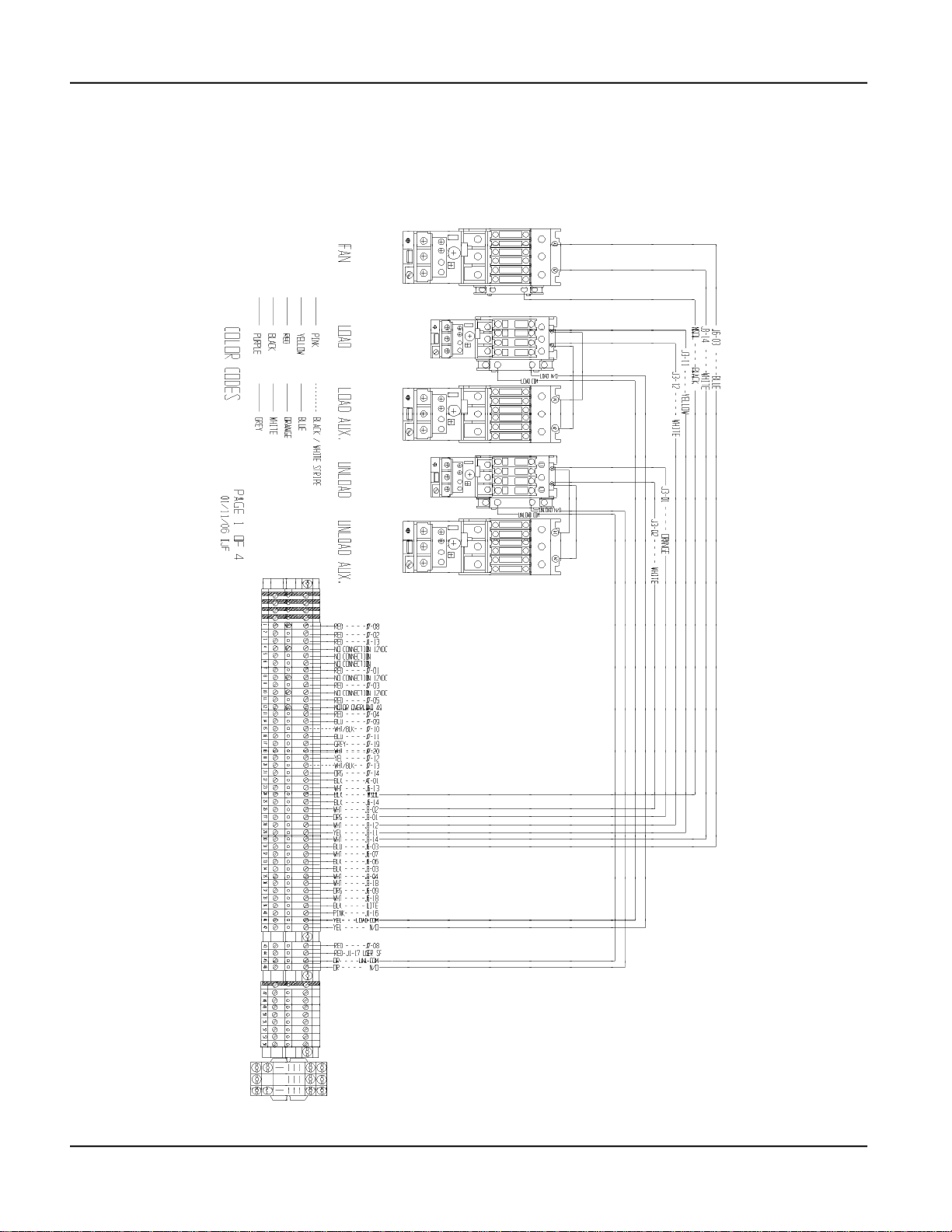
UPPER CONTROL WIRING
(UPPER CONTROL BOX)
Wiring Reference
PNEG-630-6S Troubleshooting4
Page 4
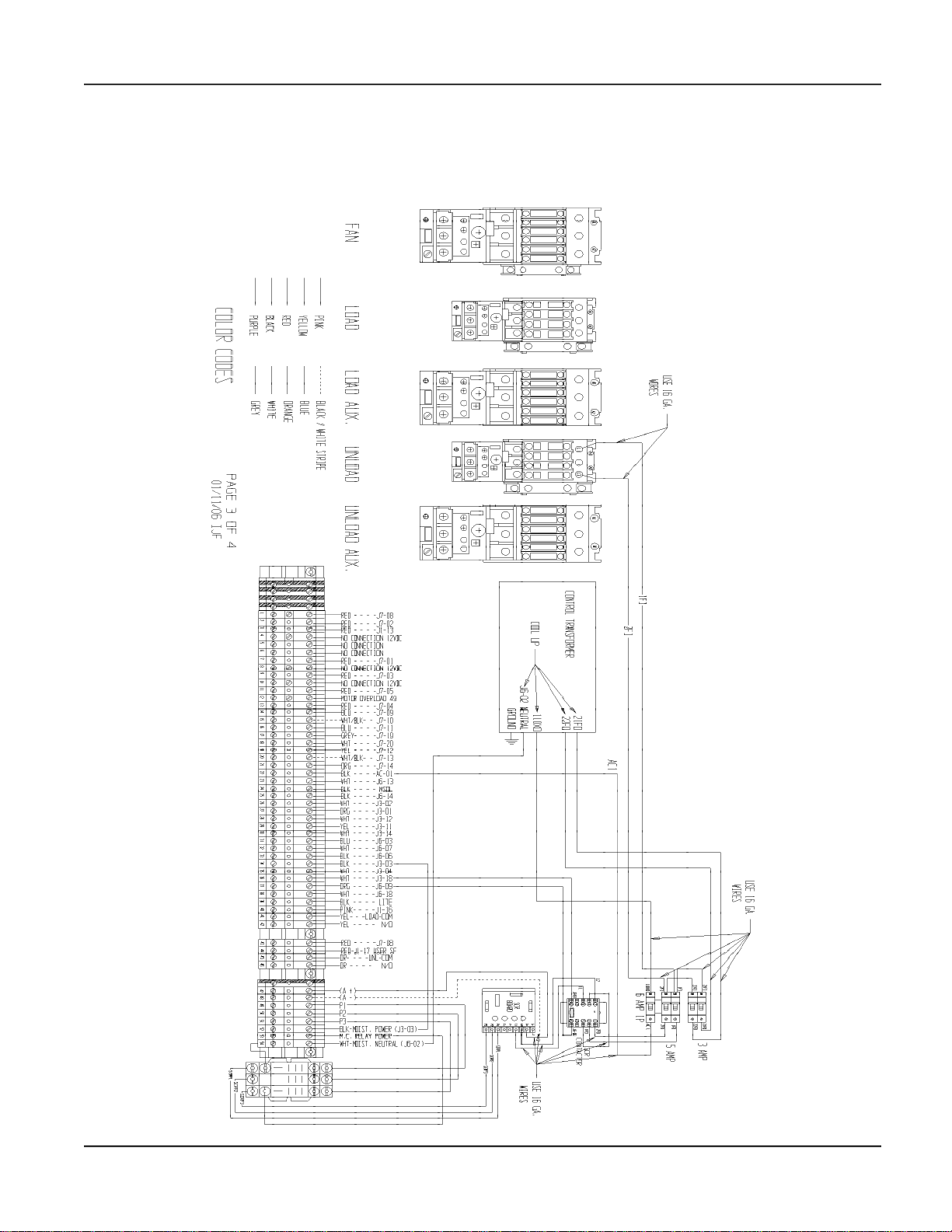
Wiring Reference
Troubleshooting
SCR DRIVE WIRING
(UPPER CONTROL BOX)
PNEG-630-6S Troubleshooting
5
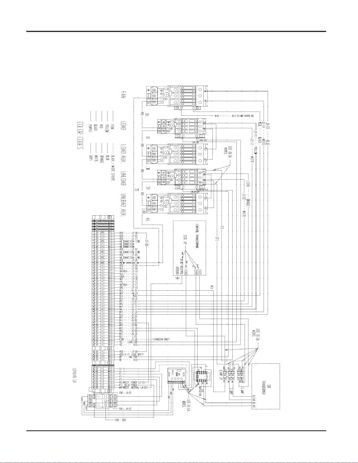
Page 5
CONTACTOR WIRING
(UPPER CONTROL BOX)
Wiring Reference
PNEG-630-6S Troubleshooting6
Page 6
Wiring Reference
Troubleshooting
SAFETY WIRING (12 VDC)
(OVERLOAD)
PNEG-630-6S Troubleshooting
7
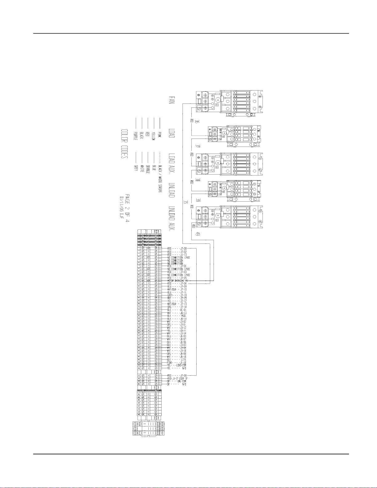
Page 7
INTERCONNECT WIRING
Wiring Reference
PNEG-630-6S Troubleshooting8
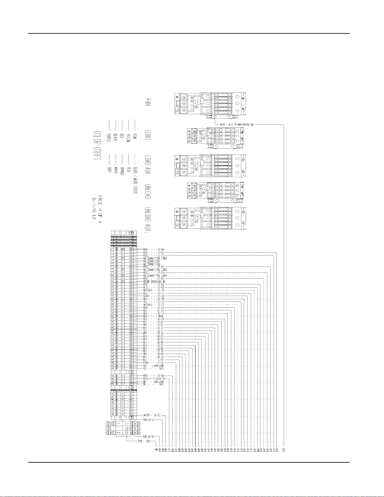
Page 8

Wiring Reference
Troubleshooting
TERMINAL STRIP & I/O WIRING OUT TO DOOR
(LOWER CONTROL BOX)
PNEG-630-6S Troubleshooting
9
Page 9

ENTERNAL WIRING
CPU TO BACK PANEL WIRING
BACK OF DOOR
(LOWER CONTROL BOX)
Wiring Reference
PNEG-630-6S Troubleshooting10
Page 10

Wiring Reference
Troubleshooting
TERMINAL STRIP TO INPUT OUTPUT BOARD
(LOWER CONTROL BOX)
PNEG-630-6S Troubleshooting
11
Page 11

INTERNAL WIRING
CPU TO SWITCH WIRING
BACK OF DOOR
(LOWER CONTROL BOX)
Wiring Reference
PNEG-630-6S Troubleshooting12
Page 12

Wiring Reference
(LOCATED ON BACK OF LOWER CONTROL BOX DOOR)
Troubleshooting
CPU BOARD
TERMINAL IDENTIFICATION
PNEG-630-6S Troubleshooting
13
Page 13

CPU BOARD
SOLENOID & SAFETY WIRING
Wiring Reference
PNEG-630-6S Troubleshooting14
Page 14

Wiring Reference
Troubleshooting
INPUT OUTPUT BOARD
TERMINAL IDENTIFICATION
(LOCATED IN LOWER CONTROL BOX)
PNEG-630-6S Troubleshooting
15
Page 15

POWER SCHEMATIC
(220 VAC 1 PH)
Wiring Reference
PNEG-630-6S Troubleshooting16
Page 16

Wiring Reference
Troubleshooting
POWER SCHEMATIC
(220 VAC 3 PH)
PNEG-630-6S Troubleshooting
17
Page 17

POWER SCHEMATIC
(440 VAC 3 PH)
Wiring Reference
PNEG-630-6S Troubleshooting18
Page 18

Wiring Reference
Troubleshooting
POWER SCHEMATIC
(575 VAC 3 PH)
PNEG-630-6S Troubleshooting
19
Page 19

CONTROL SCHEMATIC
(CPU)
Wiring Reference
PNEG-630-6S Troubleshooting20
Page 20

Wiring Reference
Troubleshooting
CONTROL SCHEMATIC
(MAIN I/O BOARD)
PNEG-630-6S Troubleshooting
21
Page 21

CONTROL SCHEMATIC
(SCR)
Wiring Reference
PNEG-630-6S Troubleshooting22
Page 22

Wiring Reference
Troubleshooting
NOTES
PNEG-630-6S Troubleshooting
23
Page 23

This Equipment shall be installed in accordance
with the current installation codes and applicable
regulations which should be carefully followed in
all cases. Authorities having jurisdiction should be
consulted before installation occurs.
The GSI Group, Inc.
1004 E. Illinois St.
Assumption, IL 62510-0020
Phone: 217-226-4421
Fax: 217-226-4420
e-mail: gsisales@grainsystems.com
internet: http://www.grainsystems.com
internet: http://www.fficorp.com
Copyright © 2006 by The GSI Group
Printed in the USA
 Loading...