

Page 1
GSI
Competitor
Portable Dryer
Models
Troubleshooting and
Reference Manual
& EMCS
2004 Revised Edition
PNEG-630
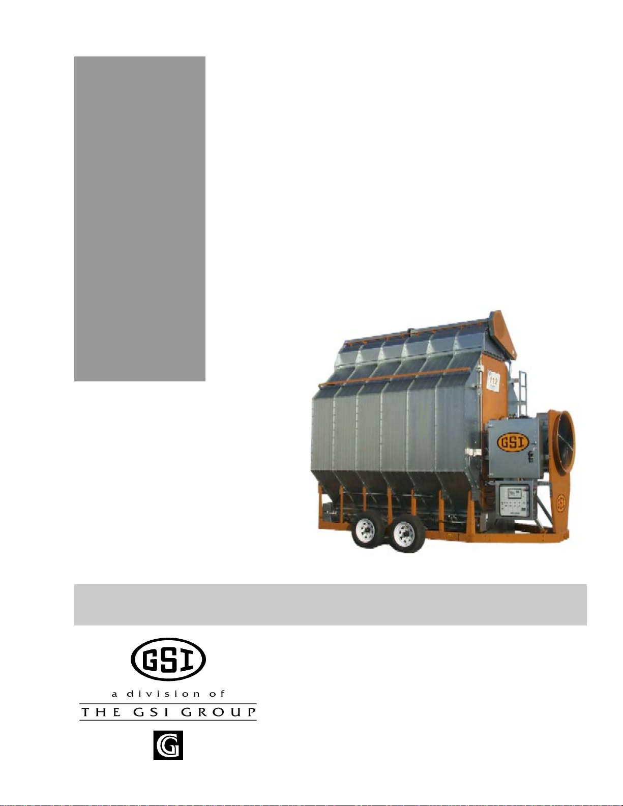
Competitor Series 2000 Dryer
Page 2

Portable Dryer Troubleshooting
Safety..................................................................................................................................................................... 3
Safety Sign Off Sheet ............................................................................................................................................ 8
EMCS Portable Dryer (1993-1998)
Safety Voltage Check Points .................................................................................................................................9
Programming Instructions for EMCS Grain Dryers .............................................................................................. 10
EMCS Display Board ............................................................................................................................................ 11
Input/Output Board Identification .......................................................................................................................... 12
EMCS Switch Replacement.........................................................................................................................13
1100 Series Control Box W iring ............................................................................................................................. 14
1100 Series Control Box W iring (New) ................................................................................................................. 15
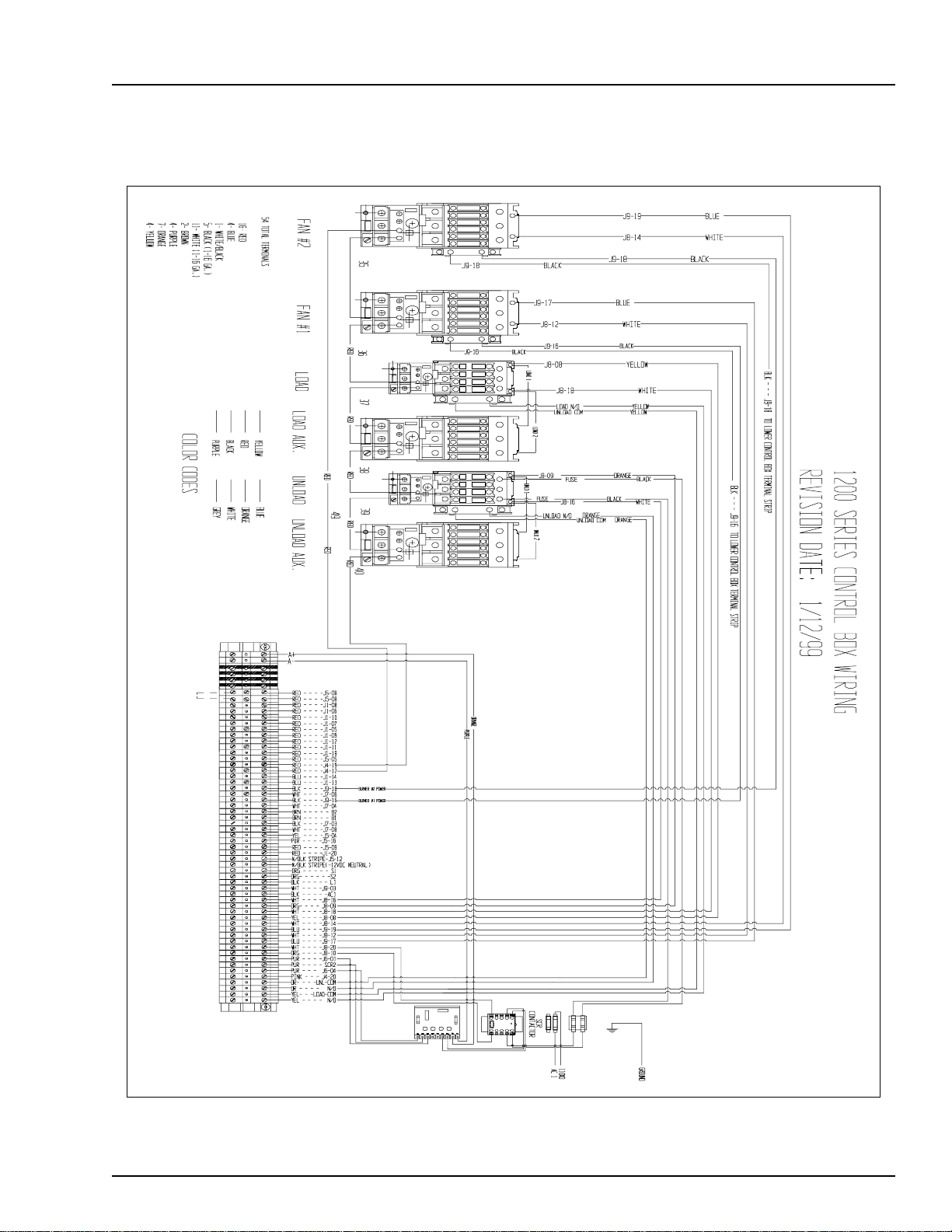
1200 Series Control Box Wiring............................................................................................................................. 16
1200 Series Control Box Wiring (New)................................................................................................................. 17
1100 Fan Lower Control Box Interconnect Strip................................................................................................... 18
1200 Fan Lower Control Box Interconnect Strip .................................................................................................. 19
Upper Control Box External Wiring....................................................................................................................... 20
Fan Housing and V apor Hi-Limit Circuit ............................................................................................................... 21
Plenum Hi-Temperature Switch ............................................................................................................................22
Fixed Grain Hi-Limit .............................................................................................................................................. 23
Grain & Plenum Hi-Limit Circuit........................................................................................................................... 24
T wo Fan Plenum and Grain Limit Switch Wiring ..................................................................................................25
Rear Discharge & Emergency Cooling Circuit ..................................................................................................... 26
Rear Discharge Mercury Switch...........................................................................................................................27
Adjustable Hi-Limit & Emergency Cooling Circuit ............................................................................................... 28
Motor Overloads .................................................................................................................................................... 29
Air Pressure Switch............................................................................................................................................... 30
Air Pressure Switch Drawing................................................................................................................................ 31
Out of Grain Safety Circuit....................................................................................................................................32
Out of Grain Safety Circuit Drawing..................................................................................................................... 33
Upper Junction Box Wiring.................................................................................................................................... 34
Meter Roll Sensor .................................................................................................................................................. 35
Meter Roll Sensor Wiring ......................................................................................................................................36
Meter Roll Reversing............................................................................................................................................. 37
Lower Junction Box Wiring ................................................................................................................................... 38
New Fenwal Board Wiring.......................................................................................................................... 39
New Fenwal Board Troubleshooting.............................................................................................................40
Flame Control Circuit............................................................................................................................................. 41
Fan Burner Circuit for Canadian Models .............................................................................................................. 42
Conversion Diagram for C Series Dryers to a Switchable Hi/Low or On/Off Burner ......................................... 43
Fan 28 LP Hi/Low-On/Off....................................................................................................................................44
Fan 28 LP On/Off Burner with Mercoid...............................................................................................................45
Fan 28 NG Hi/Low-On/Off ................................................................................................................................... 46
Fan 28 NG On/Off Burner with Mercoid .............................................................................................................. 47
Fan 42 LP Hi/Low-On/Off....................................................................................................................................48
Fan 42 LP On/Off Burner with Mercoid...............................................................................................................49
Fan 42 NG Hi/Low-On/Off ................................................................................................................................... 50
Fan 42 NG On/Off Burner with Mercoid .............................................................................................................. 51
SCR Drive Circuit.................................................................................................................................................. 52
RTD Temperature Sensor...................................................................................................................................... 53
Test Procedure for EMCS Dryers ......................................................................................................................... 54
Temperature Charts ............................................................................................................................................... 55
EMCS Troubleshooting Tips........................................................................................................................ 56
Table Of Contents
1
Page 3

Table Of Contents
Competitor Series 2000 Dryer (Picture of Dryer)(1995 to Present)......................................................65
220 Volt Single (1) Phase Power Drawing ............................................................................................................ 66
220 Volt Single (1) Phase Power Drawing (New Version) .................................................................................. 67
220 Volt Three (3) Phase Power Drawing ............................................................................................................ 68
220 Volt Three (3) Phase Power Drawing (New Version) ................................................................................... 69
220 Volt 1 Phase Power Circuit (Ladder Diagram)........................................................................................70
220 Volt 3 Phase Power Circuit (Ladder Diagram)........................................................................................71
440 Volt 3 Phase Power Circuit (Ladder Diagram)........................................................................................72
Upper Control Box Internal Wiring........................................................................................................................ 73
Series 2000 Control Box Wiring (New Version) .................................................................................................... 74
Series 2000 Control Box Wiring............................................................................................................................. 75
Series 2000 Control Box Wiring (380-460-575 3 Phase).................................................................................76
Upper Terminal Strip...................................................................................................................................77
Upper Terminal Strip (Moisture Control Hook-Up)........................................................................................78
Upper Terminal Strip (Moisture Control Relay Hook-Up)...............................................................................79
Moisture Manager to Dryer Wiring...............................................................................................................80
Input/Output Board & T erminal Strip .................................................................................................................... 81
Control Circuit (CPU/Display)(Ladder Diagram)......................................................................................... 82
Control Circuit (I/O Board)(Ladder Diagram)...............................................................................................83
Control Circuit (SCR Drive Board)(Ladder Diagram)....................................................................................84
SCR Board (Installing & Calibrating)............................................................................................................85
Upper Control Box External Wiring....................................................................................................................... 88
Input/Output Board 12 Volt .................................................................................................................................... 89
CPU Board Wiring.................................................................................................................................................90
Programming Instructions for Competitor Series Grain Dryers ............................................................................91
Programming Hook Up Diagram...........................................................................................................................92
Back of Switch Panel Layout ................................................................................................................................ 95
Back of Switch Panel Wiring................................................................................................................................. 96
Air Switch Assembly ............................................................................................................................................. 97
Air Switch Adjusting...................................................................................................................................98
Fixed Grain Hi-Limit & T emperature Sensor ........................................................................................................ 99
Out of Grain Sensor...................................................................................................................................100
Grain Temperature Sensor..........................................................................................................................101
Grain Sensor Testing..................................................................................................................................102
Grain Sensor (Locating,Testing,& Replacing)...............................................................................................103
Sensor Resistance/Temperature Chart.........................................................................................................105
Plenum Sensor (Locating,Testing & Replacing)............................................................................................106
Stern and Capacitor Diagram......................................................................................................................108
Operation Hints..........................................................................................................................................109
Series 2000 Error Conditions.......................................................................................................................111
Heater Circuit............................................................................................................................................113
Fan Burner Circuit for Canadian Models Only..............................................................................................114
Series 2000 LP 26"/28" Fan ........................................................................................................................115
Series 2000 Natural Gas 26"/28" Fan............................................................................................................116
Series 2000 LP 36"/42" Fan.........................................................................................................................117
Series 2000 Natural Gas 36"/42" Fan............................................................................................................118
Warranty....................................................................................................................................................119
Portable Dryer Troubleshooting
2
Page 4
Portable Dryer Troubleshooting
Dryer Safety
Instructions and
Information
Thank you for choosing an GSI
Grain Dryer. It is designed to provide excellent performance and service for many years.
This manual refers to the troubleshooting of the E.M.C.S.and Series
2000 Competitor models. Different
models are available for liquid propane or natural gas fuel supply, with
either single phase 230 volt, or three
phase 230, 460, 575 volt electrical
power. (Also 380 volt 50Hz).
The GSI Group Inc. recommends
contacting your local power company, and having a representative
survey your installation so the wiring is compatible with your system
and adequate power is supplied.
The principal concern of the GSI
Group, Inc. ("GSI") is your safety
and the safety of others associated
with grain handling equipment. This
manual is written to help you understand safe operating procedures, and some of the problems
that may be encountered by the operator or other personnel.
As owner and/or operator, it is your responsibility to know what requirements, hazards and precautions exist,
and to inform all personnel associated with the equipment, or who are in the dryer area. Avoid any alterations to
the equipment. Such alterations may produce a very dangerous situation, where serious injury or death may
occur.
Safety
WARNING! BE ALERT!
Personnel operating or working
around electric fans should read this
manual. This manual must be
delivered with the equipment to its
owner. Failure to read this manual
and its safety instructions is a
misuse of the equipment.
Safety Alert Symbol
The symbol shown is used to call your
attention to instructions concerning your
personal safety . Watch for this symbol;
it points out important safety precautions. It means "ATTENTION",
"WARNING", "CAUTION", and "DANGER". Read the message and be cau-
tious to the possibility of personal injury or death.
3
Page 5
Safety
Portable Dryer Troubleshooting
Grain Systems, Inc. recommends
you contact your local power company and have a representative survey your dryer installation, so your
wiring will be compatible with their
system and you will have adequate
power supplied to your unit.
A CAREFUL OPERATOR
IS THE BEST INSURANCE
AGAINST AN ACCIDENT
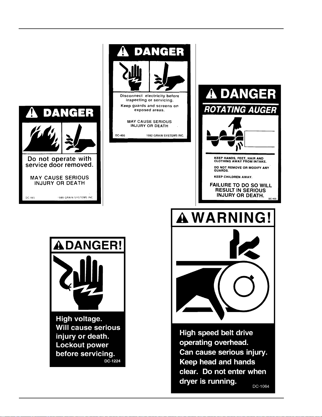
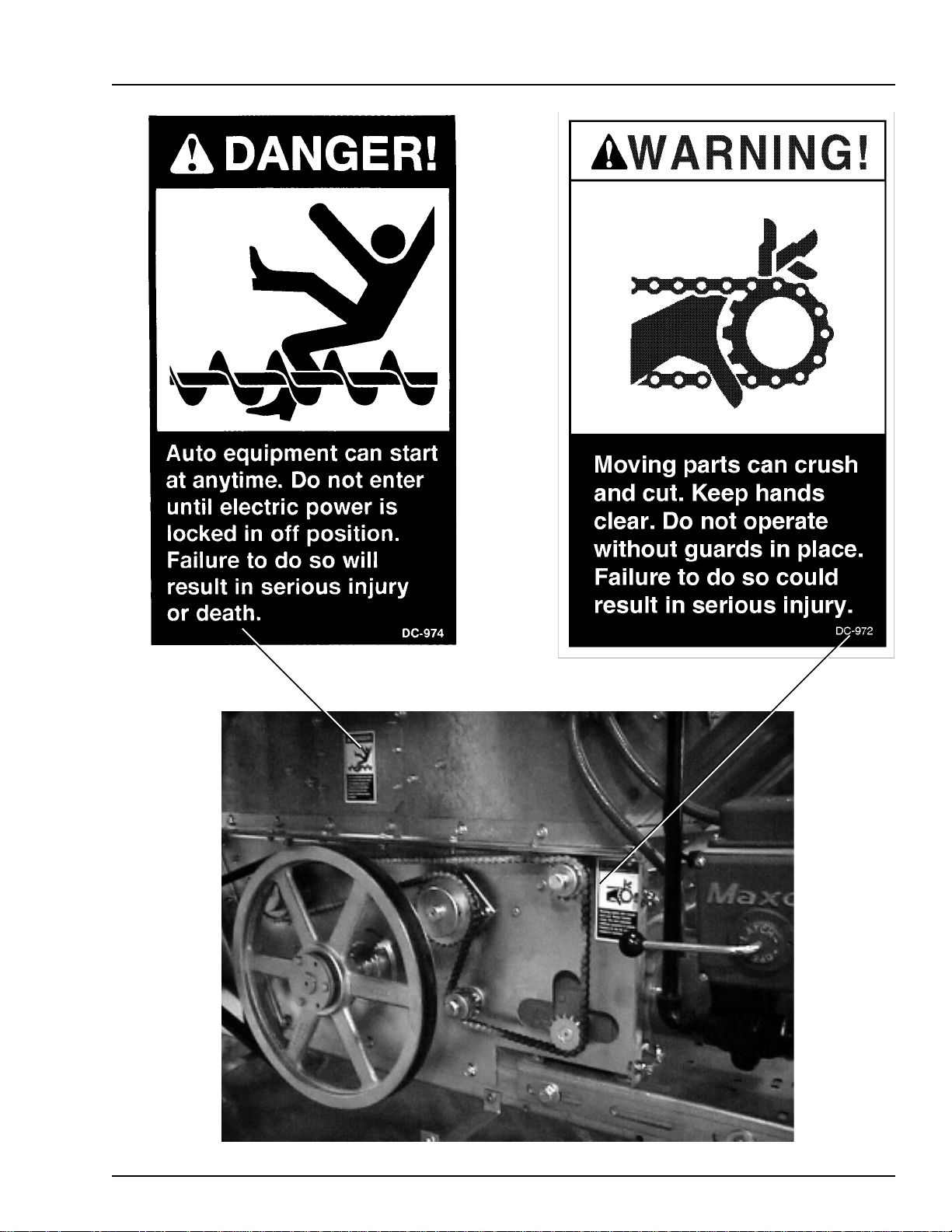
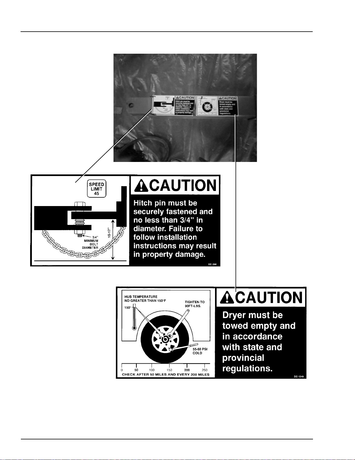
Safety decals should be read and
understood by all people in and
around the dryer area. If the following safety decals are not displayed
on your dryer, or if they are damaged, contact Grain Systems, Inc. for
replacement.
4
Page 6
Portable Dryer Troubleshooting
Safety
5
Page 7
Safety
Portable Dryer Troubleshooting
6
Page 8

Portable Dryer Troubleshooting
READ THESE INSTRUCTIONS
BEFORE OPERATION AND SERVICE
SAVE FOR FUTURE REFERENCE
1. Read and understand the operating manual before trying to operate the
dryer.
2. Power supply should be OFF for service of electrical components. Use
CAUTION in checking voltage or other procedures requiring power to
be ON.
3. Check for gas leaks at all gas pipe connections. If any leaks are detected, do not operate the dryer. Shut down and repair before further
operation.
4. Never attempt to operate the dryer by jumping or otherwise bypassing
any safety devices on the unit.
5. Set pressure regulator to avoid excessive gas pressure applied to burner
during ignition and when burner is in operation. Do not exceed maximum recommended drying temperature.
6. Keep the dryer clean. Do not allow fine material to accumulate in the
plenum or drying chamber.
Safety Precautions
Use Caution in the
Operation of this
Equipment
The design and manufacture of this
dryer is directed toward operator
safety. However, the very nature of
a grain dryer having a gas burner,
high voltage electrical equipment
and high speed rotating parts, does
present a hazard to personnel, which
can not be completely safeguarded
against, without interfering with efficient operation and reasonable access to components.
Use extreme caution in working
around high speed fans, gas-fired
heaters, augers and auxiliary conveyors, which may start without
warning when the dryer is operating on automatic control.
7. Use CAUTION in working around high speed fans, gas burners, augers
and auxiliary conveyors which START AUTOMATICALLY.
8. Do not operate in any area where combustible material will be drawn into
the fan.
9. Before attempting to remove and reinstall any propeller, make certain to
read the recommended procedure listed within the servicing section of
the manual.
10. Clean grain is easier to dry. Fine material increases resistance to airflow
and requires removal of extra moisture.
This product is intended for the use of grain handling only. Any other
use is considered a misuse of the product.
Some edges of the product components can be sharp. It is recommended
that each component of this product be examined to determine if there
are any safety considerations to be taken. Any and all necessary personal
protective equipment should be worn at all tines when handling, assembling, installing and operation of the product and/or components.
Guards are removed for illustration purpose only. All guards must be
in place before/during operation.
KEEP THE DRYER CLEAN
DO NOT ALLOW FINE
MATERIAL TO ACCUMULATE
IN THE PLENUM CHAMBER
OR SURROUNDING THE
OUTSIDE OF THE DRYER
Continued safe, dependable operation of automatic equipment depends, to a great degree, upon the
owner. For a safe and dependable
drying system, follow the recommendations within this manual, and
make it a practice to regularly inspect the operation of the unit for
any developing problems or unsafe
conditions.
Take special note of the safety precautions listed at left before attempting to operate the dryer.
7
Page 9

Safety Sign-Off Sheet
Portable Dryer Troubleshooting
Date Employer’s Signature Employee
________________________________________________________________________________________________________________________
_________________________________________________________________________________________________________________________
________________________________________________________________________________________________________________
___________________________________________________________________________________________________________________________
________________________________________________________________________________________________________________________
_____________________________________________________________________________________________________________________________
__________________________________________________________________________________________________________________________
_______________________________________________________________________________________________________________________________
_____________________________________________________________________________________________________________________________
______________________________________________________________________________________________________________________________
___________________________________________________________________________________________________________________________
______________________________________________________________________________________________________________________
_________________________________________________________________________________________________________________________
_____________________________________________________________________________________________________________________
______________________________________________________________________________________________________________________
_________________________________________________________________________________________________________________________
______________________________________________________________________________________________________________________
_______________________________________________________________________________________________________________________
______________________________________________________________________________________________________________________
______________________________________________________________________________________________________________________
_____________________________________________________________________________________________________________________
________________________________________________________________________________________________________________________
______________________________________________________________________________________________________________________
_____________________________________________________________________________________________________________
_______________________________________________________________________________________________________________________
_____________________________________________________________________________________________________________________
___________________________________________________________________________________________________________________
8
Page 10
Portable Dryer Troubleshooting
Safety Voltage Check Points
Wiring Reference
123456
FAN #
Error Message - + - + - + - + - + - + RESULT
Plenum # High Temperature J5-12 J1-11 J5-12 J1-12 J5-12 J2-11 J5-12 J2-12 J5-12 J3-11 J5-12 J3-12 12VDC
Burner # Flame not Detected J5-12 J1-9 J5-12 J1-10 J5-12 J2-9 J5-12 J2-10 J5-12 J3-9 J5-12 J3-10 12VDC
Fan # Housing High Tempera ture J5-12 J1-7 J5-12 J1-8 J5-12 J2-7 J5-12 J2-8 J5-12 J3-7 J5-12 J3-8 12VDC
Burner # Vapor High Temperature J5-12 J1-5 J5-12 J1-6 J5-12 J2-5 J5-12 J2-6 J5-12 J3-5 J5-12 J3-6 12VDC
Burner # Shutdown Loss of Airflow J5-12 J1-13 J5-12 J1-14 J5-12 J2-13 J 5-12 J2-14 J5-12 J3-13 J5-12 J3-14 Note 1
Fan # Failure No Airflow J5-12 J1-13 J5-12 J1-14 J5-12 J2-13 J 5-12 J2-14 J5-12 J3-13 J5-12 J3-14 Note 2
the fan is on.
in the closed postition. No voltage should be present if the
dryer is stopped.
3 The condition for this error will occur if the air switch is stuck
1100/1200/1300 2200/2300/2400 3300/3400/3600
Motor Ov er lo a d J5-12 J4-12 1 T his error will occur if the fan and bur ner were both operating and
Upper Fixed Grain J5-12 N/A J5-12 J 4-4 J5-12 J4-2
Middle Fixed Grain J5-12 N/A J5-12 N /A J5-12 J4-4
Misc E r rors
Upper Adjustable Grain J5-12 N/A J5-12 J4-8 J5-12 J4-6
Middle Adjustable Grain J5-12 N/A J5-12 N/A J5-12 J4-8
Lower or Left Fixed Grain J5-12 J1-19 J5-12 J1-19 J5-12 J1-19
Fan # cannot Start Check Air Switch J5-12 J1-13 J5-12 J1-14 J5-12 J2-13 J5-12 J2-14 J5-12 J3-13 J5-12 J3-14 Note 3
Lower Adjustable or Right Fixed Grain J5-12 J4-19 J5-12 J4-19 J5-12 J4-19
Auxilliary Safety Shutd o w n J5-12 J1-20 Note:
Grain Discharge Warning J5-12 J5-5 the air switch opens which indicates loss of static pressure.
Maxon Valve Shut Warning J5-12 J5-2 12 volts should be present if the fan is on.
Unknow n S a fe ty Er ror J5-12 J5-10 2 This error will occ ur if after the fan has started the air switc h does
20 Second Safety Circuit Failure J5-12 J5-6 not detect any static pressure. 12 volts should be present if
9
Page 11

Programming
Portable Dryer Troubleshooting
Programming Instructions for EMCS Grain Dryers
1. Turn Control Power on dryer to off.
2. Locate programming jack (P7) on back of computer. (See page 13).
3. Plug the DB-9 jack of the programmer into the computer's jack.
4. Be sure that the rotary switch on the programmer is set to position 8.
5. Turn on Control Power to the dryer .
6. The four (4) lights on the programmer will come on, then three (3) will go out leaving the power light still on.
7. Push the start button on the programmer to start the transfer of Software.
8. The busy light will flash until the transfer process is complete.
9. When completed the pass light will flash indicating a successful transfer.
10. If the fail light flashes then check your connections and repeat the above process.
11. T urn Control Power on dryer to off and remove the cable.
12. Turn on the dryer and the opening screens should indicate the newer version of software.
10
Page 12
Portable Dryer Troubleshooting
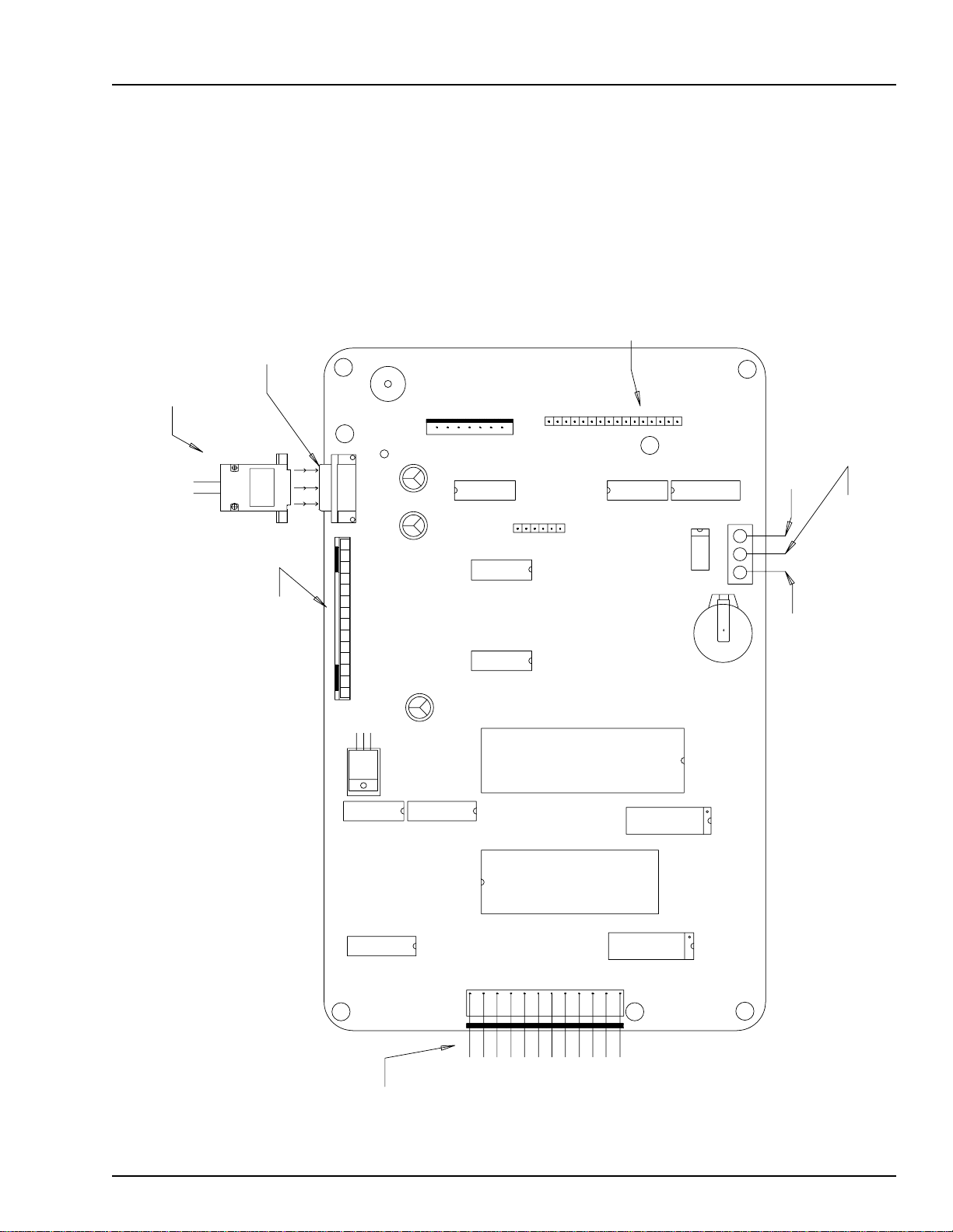
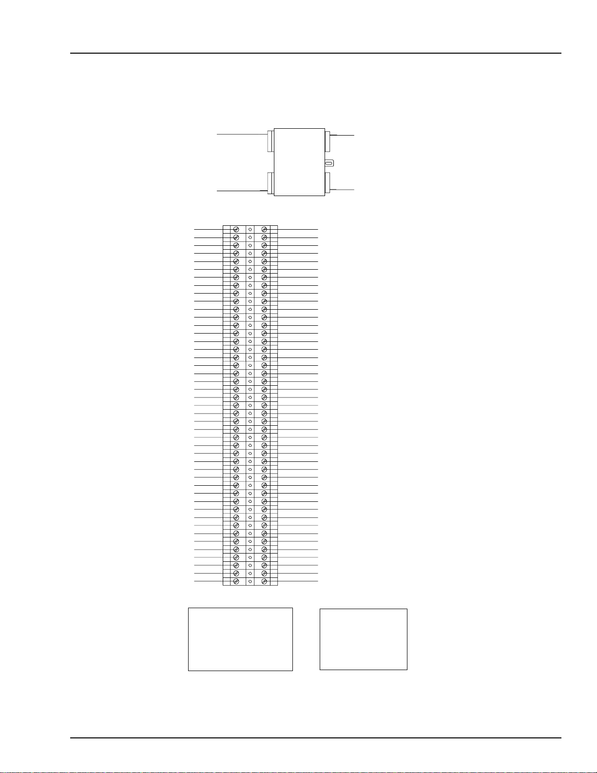
EMCS Display Board
COMPUTER
PROGRAMMING
JACK
PROGRAMMER
JACK (DB9)
SOUND
S1
P5
Programming
KEY PAD RIBBON
P4
P7
P8
COMMUNICATIONS CABLE
TO I/O BOARD
P6
TO STOP SW.
P3
3
21
U12
BATTERY (TIC)
TO START &
TO START SW.
STOP SWS.
DISPLAY
RIBBON
P1
11
Page 13
Wiring Reference
0
Portable Dryer Troubleshooting
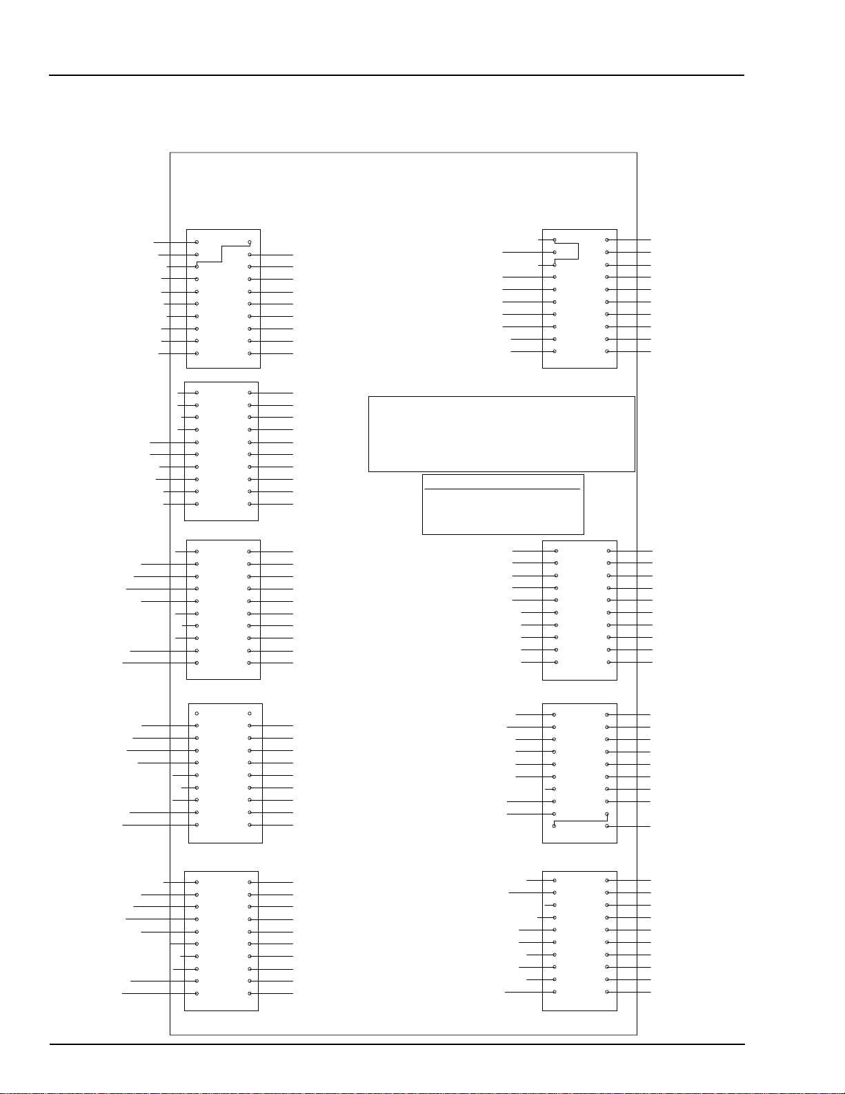
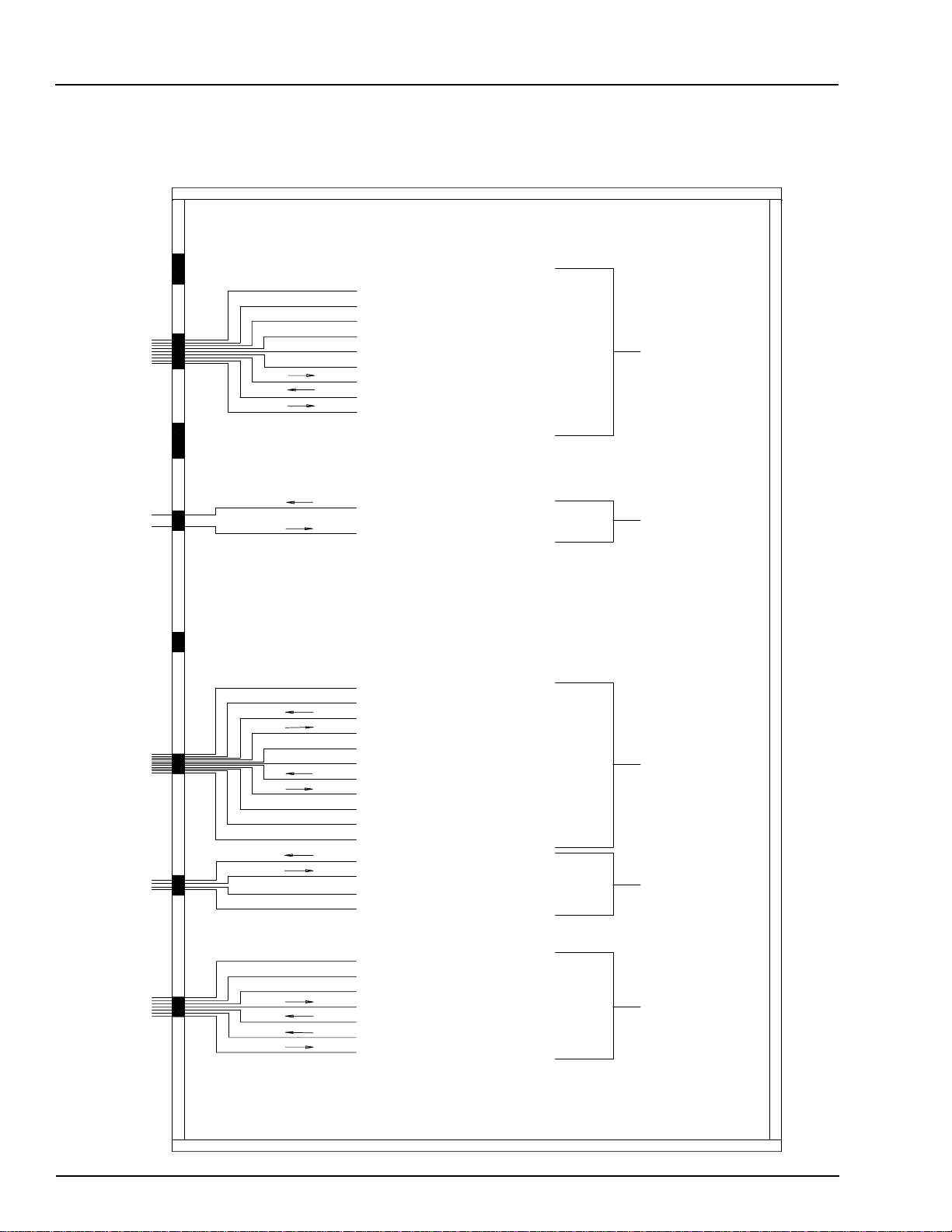
Input/Output Board Identification
120 VOLT AC OUTPUTS12 VOLT DC INPUTS
+12 LIMIT OUTPUT
12 VOLT DC NEUTRAL
METERING ROLL INPUT
12 VOLT DC NEGATIVE
12 VOLT DC NEGATIVE
SAFETY CIRCUIT INPUT
+12 VOLT LIMIT OUTPUT
FLAME SENSOR RETURN
OUT OF GRAIN SENSOR
MAXON VALVE SENSOR
MERCOID SFTY FAN#1 (CAN)
MERCOID SFTY FAN#2 (CAN)
MERCOID SFTY FAN#4 (CAN)
LOW MERCURY SWITCH (BO)
MOTOR OVERLOADS
MOISTURE CONTROL
ADJ. GRAIN (MIDDLE)
ADJ. GRAIN (UPPER)
FIXED GRAIN (MIDDLE)
FIXED GRAIN (UPPER)
BURNER #6 AUTO
BURNER #6 ON
FAN #6 AIR
FAN #6 PLENUM
FAN #6 FLAME DETECTION
FAN #6 HOUSING HIGH LIMIT
FAN #6 VAPOR HIGH LIMIT
FAN #6 AUTO
FAN #6 ON
20
19
18
17
15
16
14
13
12
11
J5
9
10
7
8
6
5
3
4
2
1
20
19
18
17
16
15
14
13
12
11
J4
10
9
7
8
6
5
3
4
1
2
20
19
18
17
16
15
14
13
12
11
J3
9
10
8
7
5
6
3
4
2
1
+12 LIMIT OUTPUT
12 VOLT DC NEGATIVE
12 VOLT DC NEGATIVE
12 VOLT DC NEGATIVE
+12 VOLT LIMIT OUTPUT
+12 VOLT LIMIT OUTPUT
REAR DISCHARGE
M.C. THERMOSTAT N.O. TERM #4
M.C. THERMOATAT N.C. TERM #6
LOWER ADJ. GRAIN HIGH LIMIT
2 SPEED UNLOAD
1 SPEED UNLOAD
UNLOAD BYPASS
LOAD SWITCH AUTO
LOAD SWITCH ON
BATCH MODE
CONTINUOUS FLOW
MERCOID SAFTY FAN#3 (CAN)
OUT OF GRAIN FOR LOAD #2
LO-HEAT THERMOSTAT (BO)HI-HEAT THERMOSTAT (BO)
BURNER #5 AUTO
BURNER #5 ON
FAN #5 AIR
FAN #5 PLENUM
FAN #5 FLAME DETECTION
FAN #5 HOUSING HIGH LIMIT
FAN #5 VAPOR HIGH LIMIT
FAN #5 AUTO
FAN #5 ON
JUMPER J1-9 TO J5-6 IS A HARDWARE TIMER FOR THE FLAME SENSOR SHUTDOWN
JUMPER J5-2 TO J5-20 IS A CONNECTION FOR THE MAXON VALVE SENS0R
JUMPER J4-12 TO J5-10 IS A HARDWARE TIMER FOR THE SAFETY SHUTDOWNS
JUMPER J1-20 TO J5-8 IS A CONNECTION FOR THE USER SUPPLLIED SAFETY
JUMPERS MUST BE INSTALLED FOR THE INPUT/OUTPUT BOARD TO OPERATE!!
120VAC POWER (INPUT)
AC NEUTRAL
120VAC POWER (INPUT)
AC NEUTRAL
AC NEUTRAL
AC NEUTRAL
AC NEUTRAL
AC NEUTRAL
FAN #1 POWER
FAN #2 POWER
JUMPERS TO BE INSTALLED FOR E-COOL
INSTALL JUMPER FROM J6-13 TO J1-5
INSTALL JUMPER FROM J6-14 TO J1-19
INSTALL JUMPER FROM J6-16 TO J5-5
INSTALL JUMPER FROM J6-17 TO J4-19
FAN #3 POWER
FAN #4 POWER
FAN #5 POWER
FAN #6 POWER
UNLOAD POWER
BUR # 4 NEUTRAL
BUR # 3 NEUTRAL
FAN # 4 NEUTRAL
FAN # 3 NEUTRAL
LOAD #2 NEUTRAL
1
2
3
4
5
6
7
8
9
10
J9
12
11
13
14
16
15
18
17
20
19
1
2
3
4
5
6
7
8
9
10
J8
11
12
13
14
15
16
18
17
20
19
120VAC POWER (OUTPUT)
AC NEUTRAL
120VAC POWER (OUTPUT)
AC NEUTRAL
AC NEUTRAL
AC NEUTRAL
AC NEUTRAL
BURNER #1 POWER
BURNER #2 POWER
BURNER #3 POWER
BURNER #4 POWER
BURNER #5 POWER
BURNER #6 POWER
LOAD POWER
SCR POWER
FAN #1 NEUTRAL
FAN #2 NEUTRAL
UNLOAD NEUTRAL
LOAD NEUTRAL
SCR NEUTRAL
12
BURNER #4 AUTO
BURNER #4 ON
FAN #4 AIR
FAN #4 PLENUM
FAN #4 FLAME DETECTION
FAN #4 HOUSING HIGH LIMIT
FAN #4 VAPOR HIGH LIMIT
FAN #4 AUTO
FAN #4 ON
USER SUPPLIED SAFETY
BURNER #2 AUTO
BURNER #2 ON
FAN #2 AIR
FAN #2 PLENUM
FAN #2 FLAME DETECTION
FAN #2 HOUSING HIGH LIMIT
FAN #2 VAPOR HIGH LIMIT
FAN #2 AUTO
FAN #2 ON
20
19
18
17
16
15
14
13
12
11
J2
10
9
7
8
5
6
3
4
1
2
20
19
18
17
16
15
14
13
12
11
J1
10
9
8
7
6
5
3
4
1
2
** IMPORTANT--JUMPERS LISTED ABOVE MUST BE INSTALLED
BURNER #3 AUTO
BURNER #3 ON
FAN #3 AIR
FAN #3 PLENUM
FAN #3 FLAME DETECTION
FAN #3 HOUSING HIGH LIMIT
FAN #3 VAPOR HIGH LIMIT
FAN #3 AUTO
FAN #3 ON
LOWER GRAIN HIGH LIMIT
BURNER #1 AUTO
BURNER #1 ON
FAN #1 AIR
FAN #1 PLENUM
FAN #1 FLAME DETECTION
FAN #1 HOUSING HIGH LIMIT
FAN #1 VAPOR HIGH LIMIT
FAN #1 AUTO
FAN #1 ON
LOAD #2 POWER
MAXON POWER
BUR #6 NEUTRAL
BUR #5 NEUTRAL
FAN #6 NEUTRAL
FAN #5 NEUTRAL
THERMOSTAT 110VAC (BO)
NC
NC
SCR P1 &
V1 FROM BR#1 (BO)
M.R.H POT 2
M.R.L POT 2 & HI SOLENOID BUR#2 (BO)
THERMOSTAT SENSOR S1
SENSOR 2 LOWER.
SENSOR 2 UPPER
ENERGENCY COOLING
AUX #6 B-COMMON
EMERGENCY COOLING
NC
1
2
3
4
5
6
7
8
9
10
J7
12
11
13
14
16
15
18
17
20
19
1
2
3
4
5
6
7
8
9
10
J6
12
11
14
13
16
15
18
17
19
20
PROCESS LIGHT
BURNER #1 NEUTRAL
BURNER #2 NEUTRAL
MAXON NEUTRAL
AC NEUTRAL
LO-HEAT POWER (BO)
HI-HEAT POWER (BO)
NC
M.R.H POT 3
M.R.L POT 3 &
HIGH SOLENOID BUR#1 (BO)
SCR P3 & V1 FROM BR#2 (B
SENSOR 1 LOWER
SENSOR 1 UPPER
THERMOSTAT SENSOR S2
AUX #6 A-N.C.
EMERGENCY COOLING
EMERGENCY COOLING
NC
NC
Page 14
Portable Dryer Troubleshooting
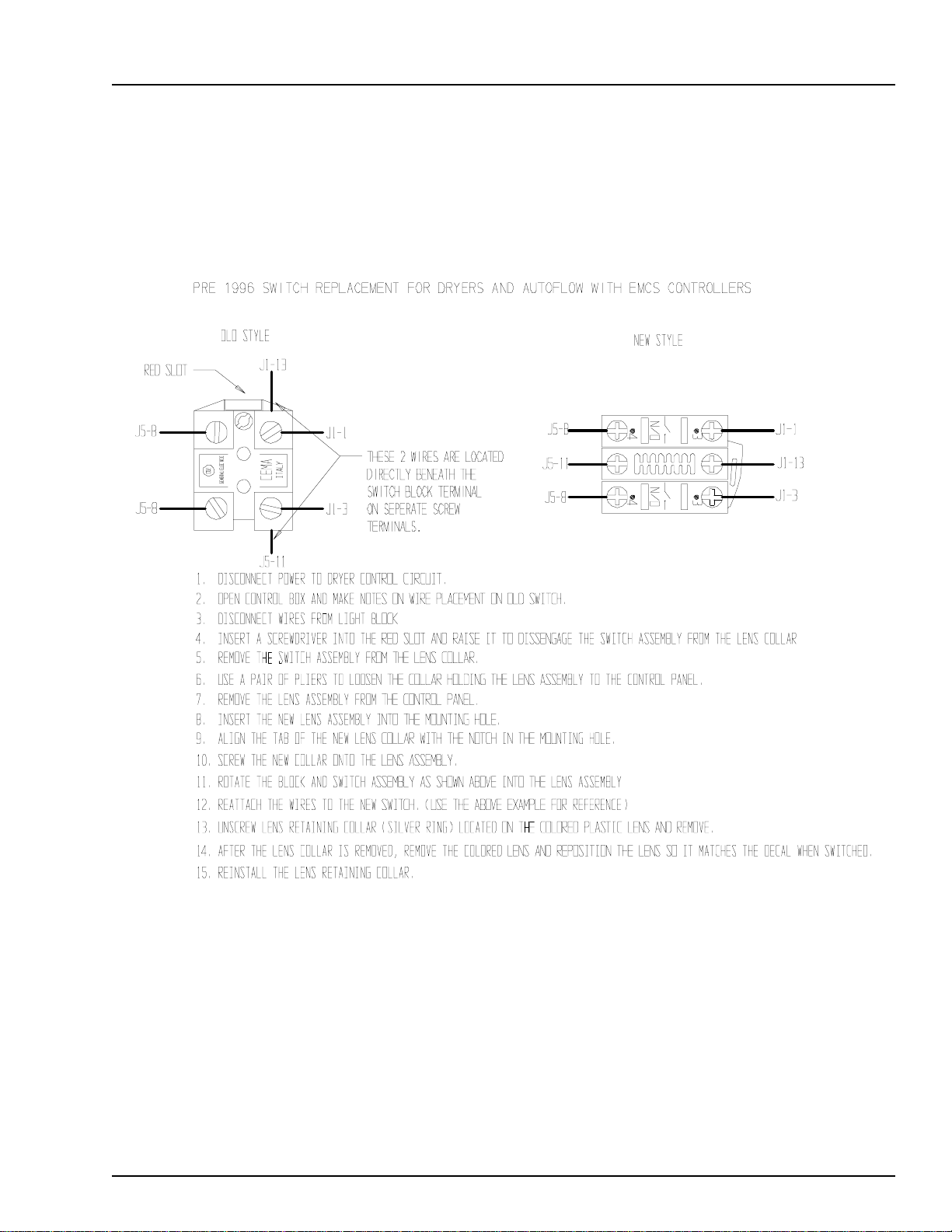
Switch Replacement for EMCS Dryer
Switch Replacement
Switch N/O Contact Block - Part No. D63-0006
Switch Light Block - D01-0455
13
Page 15
Wiring Reference
Portable Dryer Troubleshooting
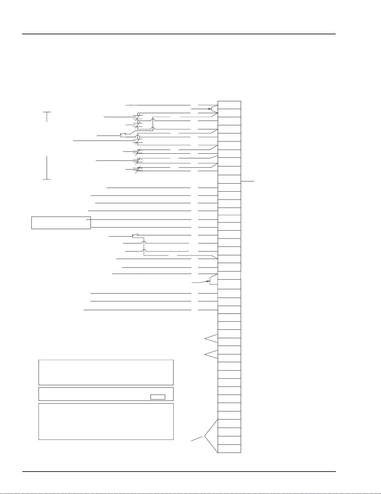
1100 Series Control Box Wiring
1100 FAN TO CONTROL BOX WIRING
AIR PRESSURE SWITCH +12VDC
HOUSING HIGH LIMIT
VAPOR HIGH LIMIT (LP ONLY)
FLAME DETECTION
PLENUM
LEFT FIXED GRAIN HI LIMIT
SAFETY CIRCUIT
*REAR DISCHARGE
RIGHT FIXED GRAIN HI LIMIT
AIR PRESSURE SWITCH
BURNER POWER
BURNER NEUTRAL
BURNER LIGHT
USED ON SINGLE FAN
NAT GAS ONLY
K OTHER SIDE
N/C) SAFETY
5-8 OR J5-9 --
MAXON POWER
MAXON NEUTRAL
OUT OF GRAIN SENSOR
*
LEFT METERING ROLL SENSOR
*
RIGHT METERING ROLL SENSOR
METERING ROLL 12 VOLTS
CUSTOMER SUPPLIED SAFETY
METERING ROLL NEUTRAL
TEMP SENSORS
TEMP SENSORS
WORK LIGHT
DRYER SAFETY CIRCUIT ALWAYS STARTS ON J5-8 AND ENDS
ON J4-12.USING THE J5-12 TERMINAL FOR NEGATIVE,
THERE SHOULD BE 12 VOLTS DC ON EACH TERMINAL FROM
J5-8 TO J4-12.
WHEN CHECKING FOR 12 VOLTS DC ALWAYS PUT THE
NEGATIVE PROBE OF VOLT METER TO TERMINAL J5-12
SAFETY CIRCUIT IN BOLD IS FOR FLAME DETECTION ONLY.
EACH OF THE TERMINALS CONNECTED TO IT CAN LOOSE
12 VDC FOR 20 SECONDS BEFORE A SHUTDOWN OCCURS.
THIS GIVES THE BURNER CIRCUIT TIME TO SENSE FLAME.
ALL OTHER SAFETY CONNECTIONS MUST HAVE 12 VDC
PRESENT AT ALL TIMES TO OPERATE PROPERLY.
*LOCATED AT REAR OF DRYER
1100EW98.PRT REV. DATE 4/10/98
RELAY CONTACTS LOCATED
IN DRYER FAN CAN BOX
MERCURY SWITCH LOCATED
ON TOP OF DRYER
120VAC FOR AUX UNLOAD CONTACTOR COIL
120VAC FOR AUX LOAD CONTACTOR COIL
AUX CONTACT POINTS FOR LOAD AND UNLOAD SYSTEMS
ALL VOLTAGE SUPPLIED BY USER
42 TOTAL TERMINALS
WIRINGDESCRIPTION
NEED JUMPER
OR
YEL
RED
BRN
RED
BLK
NEED JUMPER
RED
RED
YEL
PUR
OR
BLU
OR
OR
OR
BLU
BLK
WHT
BRN
PUR
WHT
BLK
YEL
BLU
RED
BLK
WHT
BLK
RED
ALL SAFETIES MUST BE CLOSED FOR DRYER TO OPERATE
J5-8
J5-8
J1-7
J1-5
J1-9
J1-11
J1-19
J5-5
J4-19
J4-12
J1-13
J9-16
J7-4
B1
J7-3
J7-8
J5-4
J5-16
J5-19
J5-9
J1-20
J5-12
-12VDC
S1
S2
L1
J8-16
J8-9
J8-18
J8-8
J8-12
J9-17
J8-20
J8-10
J6-1
SCR 2
J6-4
U-COM
U-N/O
L-COM
L-N/O
12 VOLTS DC (RED)
12 VOLTS DC (RED)
12 VOLTS DC (RED)
12 VOLTS DC (RED)
12 VOLTS DC (RED)
12 VOLTS DC (RED)
12 VOLTS DC (RED)
12 VOLTS DC (RED)
12 VOLTS DC (RED)
MOTOR OVERLOADS
12 VOLTS DC (BLUE)
120 VAC (BLACK)
120 VAC NEUT (WHITE)
120 VAC (BLUE)
120 VAC (BLACK)
120 VAC NEUT (WHITE)
12 VOLTS DC (YELLOW)
METER ROLL PULSE (PUR)
NO LONGER USED
12 VOLTS DC (RED)
12 VOLTS DC (RED)BLK
12 VOLTS DC NEG (WHITE)
TEMP SENSOR (ORANGE)
TEMP SENSOR (ORANGE)
120 VAC (BLACK)
120 VAC NEUT (WHITE)J9-3
120 VAC (BLACK)AC 1
120 VAC NEUT (WHITE)
120 VAC (ORANGE)
120 VAC NEUT (WHITE)
120 VAC (YELLOW)
120 VAC NEUT (WHITE)
120 VAC (BLUE)
120 VAC NEUT (WHITE)
120 VAC (ORANGE)
CONTROL POT P1 (PUR)
CONTROL POT P2 (PUR)
CONTROL POT P3 (PUR)
UNLOAD AUX COM(ORANGE)
UNLOAD AUX N/O(ORANGE)
LOAD AUX COM (YELLOW)
LOAD AUX N/O (YELLOW)
COLORVOLTAGE
14
Page 16

Portable Dryer Troubleshooting
1100 Series Control Box Wiring (New Version)
Wiring Reference
15
Page 17
Wiring Reference
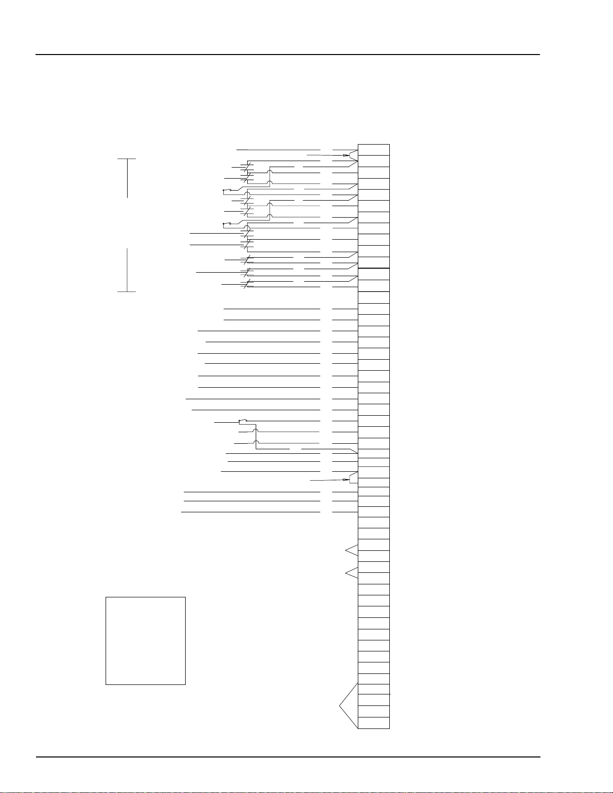
1200 Series Control Box Wiring
DESCRIPTION
WIRING
Portable Dryer Troubleshooting
52 TOTAL TERMINALS
TERMINAL
COLORVOLTAGE
HOOK OTHER SIDE
OF (N/C) SAFETY
TO J5-8 OR J5-9 --
53 TOTAL TERMINALS
15 - RED
4 - BLUE
1 - WHITE/BLACK
3 - BLACK (1-16GA)
9 - WHITE (1-16GA
2 - BROWN
4 - PURPLE
4 - ORANGE)
*LOCATED AT REAR OF DRYER
1200EW98.PRT REV. DATE 3/5/98
AIR PRESSURE SWITCH +12VDC
FAN #2 HOUSING HIGH LIMIT
FAN #2 VAPOR HIGH LIMIT
FAN #2 FLAME DETECTION
FAN #1 HOUSING HIGH LIMIT
FAN #1 VAPOR HIGH LIMIT
FAN #1 FLAME DETECTION
FAN #2 PLENUM
SAFETY CIRCUIT
FAN #1 PLENUM
FIXED GRAIN HIGH LIMIT
*REAR DISCHARGE
ADJ. GRAIN HIGH LIMIT
FAN #2 PRESSURE SWITCH
FAN #1 PRESSURE SWITCH
BURNER #2 POWER
BURNER #2 NEUTRAL
BURNER #1 POWER
BURNER #1 NEUTRAL
BURNER #2 LIGHT
BURNER #1 LIGHT
MAXON POWER
MAXON NEUTRAL
OUT OF GRAIN SENSOR
*LEFT METERING ROLL SENSOR
*RIGHT METERING ROLL SENSOR
METERING ROLL 12 VOLTS
CUSTOMER SUPPLIED SAFETY RED
METERING ROLL NEGATIVE
TEMP SENSOR
TEMP SENSOR
RELAY CONTACTS LOCATED
IN FAN CAN CONTROL BOX
RELAY CONTACTS LOCATED
IN FAN CAN CONTROL BOX
MERCURY SWITCH LOCATED
ON TOP OF DRYER
120VAC FOR AUX UNLOAD CONTACTOR COIL
120VAC FOR AUX LOAD CONTACTOR COIL
AUX CONTACT POINTS FOR LOAD AND UNLOAD SYSTEMS
ALL VOLTAGE SUPPLIED BY USER
NEED JUMPER
RED
RED
RED
BRN
RED
BLK
NEED JUMPER
RED
RED
OR
YEL
PUR
OR
OR
YEL
PUR
OR
YEL
BLU
OR
OR
RED
MOTOR OVERLOADS
BLU
BLU
BLK
WHT
BLK
WHT
BRN
BRN
PUR
WHT
BLK
YEL
BLU
RED
BLK
WHT
BLK
RED
ALL SAFETIES MUST BE CLOSED FOR DRYER TO OPERATE
J5-8
J5-8
J1-8
J1-6
J1-10
J1-7
J1-5
J1-9
J1-12
J1-11
J1-19
J5-5
J4-19
J4-12
J1-14
J1-13
J9-18
J7-6
J9-16
J7-4
B2
B1
J7-3
J7-8
J5-4
J5-16
J5-19
J5-9
J1-20
J5-12
-12VDC
S1
S2
L1 WORK LIGHT
J9-3
J8-16
J8-9
J8-18
J8-8
J8-14
J9-19
J8-12
J9-17
J8-20
J8-10
J6-1
SCR 2
J6-4
U-COM
U-N/O
L-COM
L-N/O
12 VOLTS DC (RED)
12 VOLTS DC (RED)
12 VOLTS DC (RED)
12 VOLTS DC (RED)
12 VOLTS DC (RED)
12 VOLTS DC (RED)
12 VOLTS DC (RED)
12 VOLTS DC (RED)
12 VOLTS DC (RED)
12 VOLTS DC (RED)
12 VOLTS DC (RED)
12 VOLTS DC (RED)
12 VOLTS DC (RED)
12 VOLTS DC (BLUE)
12 VOLTS DC (BLUE)
120 VAC (BLACK)
120 VAC NEUT (WHITE)
120 VAC (BLACK)
120 VAC NEUT (WHITE)
120 VAC (BROWN)
120 VAC (BROWN)
120 VAC (BLACK)
120 VAC NEUT (WHITE)
12 VOLTS DC (YELLOW)
METER ROLL PULSE (PUR)
NO LONGER USED
12 VOLTS DC (RED)
12 VOLTS DC (RED)
12 VOLTS DC NEG (WHITE)
TEMP SENSOR (ORANGE)
TEMP SENSOR (ORANGE)
120 VAC (BLACK)
120 VAC NEUT (WHITE)
120 VAC (BLACK)AC 1
120 VAC NEUT (WHITE)
120 VAC (ORANGE)
120 VAC NEUT (WHITE)
120 VAC (YELLOW)
120 VAC NEUT (WHITE)
120 VAC (BLUE)
120 VAC NEUT (WHITE)
120 VAC (BLUE)
120 VAC NEUT (WHITE)
120 VAC (ORANGE)
CONTROL POT P1 (PUR)
CONTROL POT P2 (PUR)
CONTROL POT P3 (PUR)
UNLOAD AUX COM(ORANGE)
UNLOAD AUX N/O(ORANGE)
LOAD AUX COM (YELLOW)
LOAD AUX N/O (YELLOW)
16
Page 18
Portable Dryer Troubleshooting
1200 Series Control Box Wiring (New Version)
Wiring Reference
17
Page 19

Wiring Reference
1100 Fan Lower Control Box Interconnect Strip
Portable Dryer Troubleshooting
J9-1
LOAD
LINE
AC-1
EMERGENCY COOLING JUMPERS
INSTALL J6-13 TO J1-5
INSTALL J6-14 TO J1-19
INSTALL J6-16 TO J5-5
INSTALL J6-17 TO J4-19
L1
B1
S1
S2
SCR2
J1-5
J1-7
J1-9
J1-11
J1-13
J1-19
J1-20
J4-12
J4-19
J5-4
J5-5
J5-8
J5-9
J5-12
J5-16
J5-19
J6-1
J6-4
J7-3
J7-4
J7-8
J8-8
J8-9
J8-10
J8-12
J9-3
EMI FILTER
D03-0181
BLACK - 120 VAC - OUTSIDE LIGHT
BROWN - 120 VAC - BURNER #1 LIGHT
ORANGE - TEMPERATURE SENSOR
ORANGE - TEMPERATURE SENSOR
PURPLE - CONTROL POT P2
RED - 12 VDC - FAN #1 VAPOR HIGH LIMIT
RED - 12 VDC - FAN #1 HOUSING HIGH LIMIT
RED - 12 VDC - FAN #1 FLAME DETECTION
RED - 12 VDC - FAN #1 PLENUM HIGHT LIMIT
BLUE - 12 VDC - FAN #1 AIR SWITCH
RED - 12 VDC - LOWER FIXED GRAIN LIMIT
RED - 12 VDC - USER SUPPLIED SAFETY
RED - 12 VDC - MOTOR OVERLOADS
RED - 12 VDC - LOWER ADJUSTABLE GRAIN HIGH LIMIT
YELLOW - 12 VDC - OUT OF GRAIN SENSOR
RED - 12 VDC - REAR DISCHARGE SWITCH
RED - 12 VDC - 12 VOLT SUPPLY
RED - 12 VDC - 12 VOLT SUPPLY
WHITE - 12 VDC NEG - 12 VOLT SUPPLY NEGATIVE
PURPLE -TIMING PULSE- LEFT METERING ROLL PULSE
PURPLE -TIMING PULSE- RIGHT METERING ROLL PULSE
PURPLE - CONTROL POT P1
PURPLE - CONTROL POT P3
BLACK - 120 VAC - MAXON POWER
WHITE - AC NEUTRAL - BURNER NEUTRAL
WHITE - AC NEUTRAL - MAXON NEUTRAL
YELLOW - 120 VAC - LOAD POWER
ORANGE - 120 VAC - UNLOAD POWER
ORANGE - 120 VAC - SCR POWER
WHITE - AC NEUTRAL - FAN #1 NEUTRAL
5VB1
J9-3
J8-16 WHITE - AC NEUTRAL - UNLOAD NEUTRAL
J8-18
J8-20
J9-16
J9-17
WHITE - AC NEUTRAL - LOAD NEUTRAL
WHITE - AC NEUTRAL - SCR NEUTRAL
BLACK - 120 VAC - BURNER #1 POWER
BLUE - 120 VAC - FAN #1 POWER
18
35 - D01-0531 ENTRELEC TERMINALS
2 - D01-0533 END STOPS
1 - D01-0532 BLANK PROTECTOR END
I/O BOARD JUMPERS
INSTALL J1-9 TO J5-6
INSTALL J5-2 TO J5-20
INSTALL J4-12 TO J5-10
INSTALL J1-20 TO J5-8
Page 20
Portable Dryer Troubleshooting
1200 Fan Lower Control Box Interconnect Strip
Wiring Reference
J9-1
LOAD
J9-3
L1
B1
B2
S1 ORANGE - TEMPERATURE SENSOR
S2 ORANGE - TEMPERATURE SENSOR
SCR2
J1-5
J1-6
J1-7
J1-8
J1-9
J1-10
J1-11
J1-12
J1-13
J1-14
J1-19
J1-20
J4-12
J4-19
J5-4
J5-5
J5-8
J5-9
J5-12
J5-16
J5-19
J6-1
J6-4
J7-3
J7-4
J7-8
J8-8
J8-9
J8-10
J8-12
J8-18
J8-20
J9-16
LINE
5VB1
EMI FILTER
D03-0181
BLACK - 120 VAC - OUTSIDE LIGHT
BROWN - 120 VAC - BURNER #1 LIGHT
BROWN - 120 VAC - BURNER #2 LIGHT
PURPLE - CONTROL POT P2
RED - 12 VDC - FAN #1 VAPOR HIGH LIMIT
RED - 12 VDC - FAN #2 VAPOR HIGH LIMIT
RED - 12 VDC - FAN #1 HOUSING HIGH LIMIT
RED - 12 VDC - FAN #2 HOUSING HIGH LIMIT
RED - 12 VDC - FAN #1 FLAME DETECTION
RED - 12 VDC - FAN #2 FLAME DETECTION
RED - 12 VDC - FAN #1 PLENUM HIGHT LIMIT
RED - 12 VDC - FAN #2 PLENUM HIGHT LIMIT
BLUE - 12 VDC - FAN #1 AIR SWITCH
BLUE - 12 VDC - FAN #2 AIR SWITCH
RED - 12 VDC - LOWER FIXED GRAIN LIMIT
RED - 12 VDC - USER SUPPLIED SAFETY
RED - 12 VDC - MOTOR OVERLOADS
RED - 12 VDC - LOWER ADJUSTABLE GRAIN HIGH LIMIT
YELLOW - 12 VDC - OUT OF GRAIN SENSOR
RED - 12 VDC - REAR DISCHARGE SWITCH
RED - 12 VDC - 12 VOLT SUPPLY
RED - 12 VDC - 12 VOLT SUPPLY
WHITE - 12 VDC NEG - 12 VOLT SUPPLY NEGATIVE
PURPLE -TIMING PULSE- LEFT METERING ROLL PULSE
PURPLE -TIMING PULSE- RIGHT METERING ROLL PULSE
PURPLE - CONTROL POT P1
PURPLE - CONTROL POT P3
BLACK - 120 VAC - MAXON POWER
WHITE - AC NEUTRAL - BURNER #1 NEUTRAL
WHITE - AC NEUTRAL - BURNER #2 NEUTRALJ7-6
WHITE - AC NEUTRAL - MAXON NEUTRAL
YELLOW - 120 VAC - LOAD POWER
ORANGE - 120 VAC - UNLOAD POWER
ORANGE - 120 VAC - SCR POWER
WHITE - AC NEUTRAL - FAN #1 NEUTRAL
WHITE - AC NEUTRAL - FAN #2 NEUTRALJ8-14
WHITE - AC NEUTRAL - UNLOAD NEUTRALJ8-16
WHITE - AC NEUTRAL - LOAD NEUTRAL
WHITE - AC NEUTRAL - SCR NEUTRAL
BLACK - 120 VAC - BURNER #1 POWER
BLUE - 120 VAC - FAN #1 POWERJ9-17
BLACK - 120 VAC - BURNER #2 POWERJ9-18
BLUE - 120 VAC - FAN #2 POWERJ9-19
AC-1
J9-3
EMERGENCY COOLING JUMPERS
INSTALL J6-13 TO J1-5
INSTALL J6-14 TO J1-19
INSTALL J6-16 TO J5-5
INSTALL J6-17 TO J4-19
45 - D01-0531 ENTRELEC TERMINALS
2 - D01-0533 END STOPS
1 - D01-0532 BLANK PROTECTOR ENDS
I/O BOARD JUMPERS
INSTALL J1-9 TO J5-6
INSTALL J5-2 TO J5-20
INSTALL J4-12 TO J5-10
INSTALL J9-1 TO J9-5
19
Page 21
Wiring Reference
Portable Dryer Troubleshooting
Upper Control Box External Wiring
BLACK FROM J9-16 TO L1 ON FENWAL BOARD 120VAC POWER
WHITE FROM J7-04 TO L2 ON FENWAL BOARD 120VAC NEUTRAL
BROWN TO B1 FROM V1 ON FENWAL BOARD 120VAC
ORANGE FROM J1-09 TO FLAME DETECTION RELAYS
ORANGE FROM J5-08 TO FLAME DETECTION RELAYS
WHITE/BLACK STRIP J5-12 12VDC NEGATIVE
YELLOW TO J1-07 FROM HOUSING HIGH LIMIT SWITCH
RED FROM J5-08 TO HOUSING & VAPOR HIGH LIMIT SWITCHES
PURPLE TO J1-05 FROM VAPOR HIGH LIMIT SWITCH
TO FAN CONTROL BOX
BLUE FROM J5-08 TO AIRSWITCH COMMON TERMINAL
BLUE TO J1-13 FROM AIRSWITCH N.O. TERMINAL
WHITE TO S1 FROM RIGHT GRAIN TEMPERATURE SENSOR
BLACK TO S2 FROM RIGHT GRAIN TEMPERATURE SENSOR
RED FROM J1-11 TO LEFT GRAIN HIGH LIMIT SWITCH
ORANGE TO J1-19 FROM LEFT GRAIN HIGH LIMIT SWITCH
PURPLE J7-03 MAXON POWER 120VAC (NATURAL GAS ONLY)
WHITE J7-08 MAXON 120VAC NEUTRAL (NATURAL GAS ONLY)
BROWN FROM J1-19 TO REAR DISCHARGE SWITCH
ORANGE TO J5-05 FROM REAR DISCHARGE SWITCH
RED 16 GA. A+ SCR DRIVE MOTOR
BLACK 16 GA. A- SCR DRIVE MOTOR
GREEN 16 GA. SCR DRIVE MOTOR GROUND
BLACK FROM J5-09 TO LOAD MERCURY SWITCH
BLACK TO J5-04 FROM LOAD MERCURY SWITCH
WHITE FROM J9-03 TO OUTSIDE LIGHT AC NEUTRAL
RED FROM L1 120VAC TO OUTSIDE LIGHT POWER
TO AIRSWITCH ASSEMBLY
TO LOWER JUNCTION BOX
TO UPPER JUNCTION BOX
20
YELLOW FROM J1-05 TO PLENUM HIGH LIMIT SWITCH
WHITE TO S1 FROM GRAIN TEMPERATURE SENSOR
BLACK TO S2 FROM GRAIN TEMPERATURE SENSOR
BLUE TO J1-11 FROM PLENUM HIGH LIMIT SWITCH
YELLOW FROM J1-05 TO PLENUM HIGH LIMIT SWITCH
RED FROM J5-05 TO RIGHT GRAIN HIGH LIMIT SWITCH
ORANGE TO J4-19 FROM RIGHT GRAIN HIGH LIMIT SWITCH
TO PLENUM AND RIGHT
FIXED GRAIN HIGH LIMIT
SWITCHES AND TEMPERATURE
SENSORS
Page 22
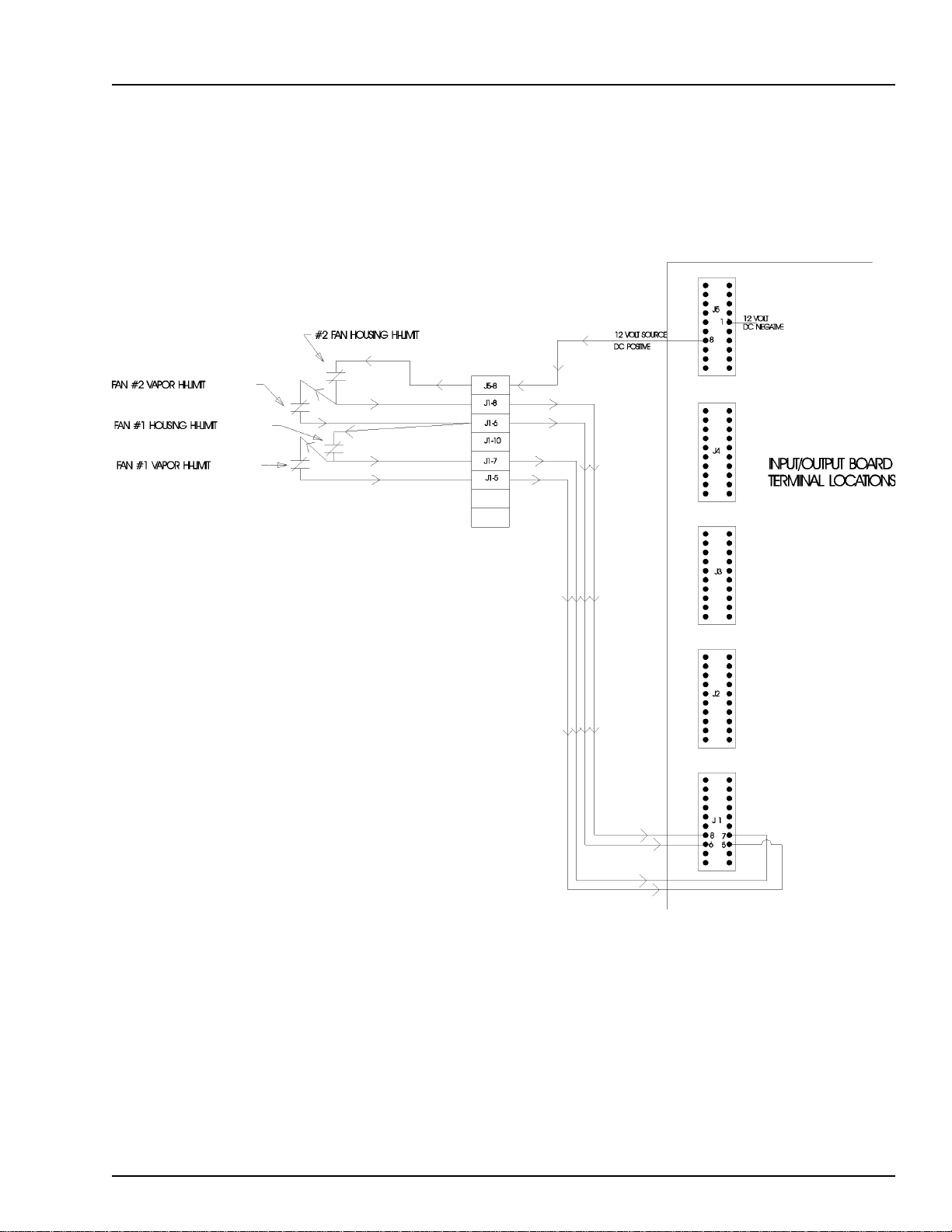
Portable Dryer Troubleshooting
Fan Housing and Vapor Hi-Limit Circuit
Wiring Reference
21
Page 23
Wiring Reference
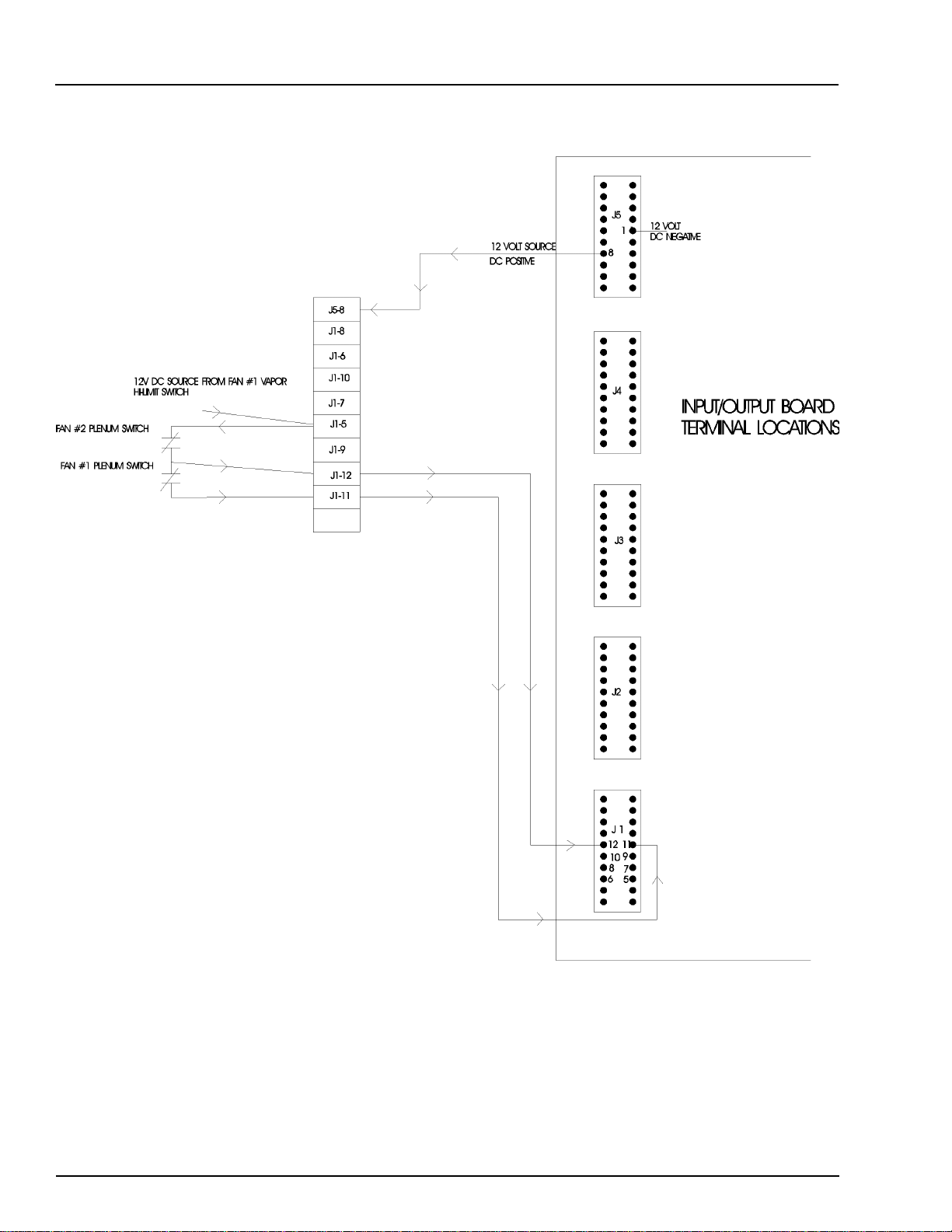
Portable Dryer Troubleshooting
Plenum Hi-Temperature Switch
22
Page 24
Portable Dryer Troubleshooting
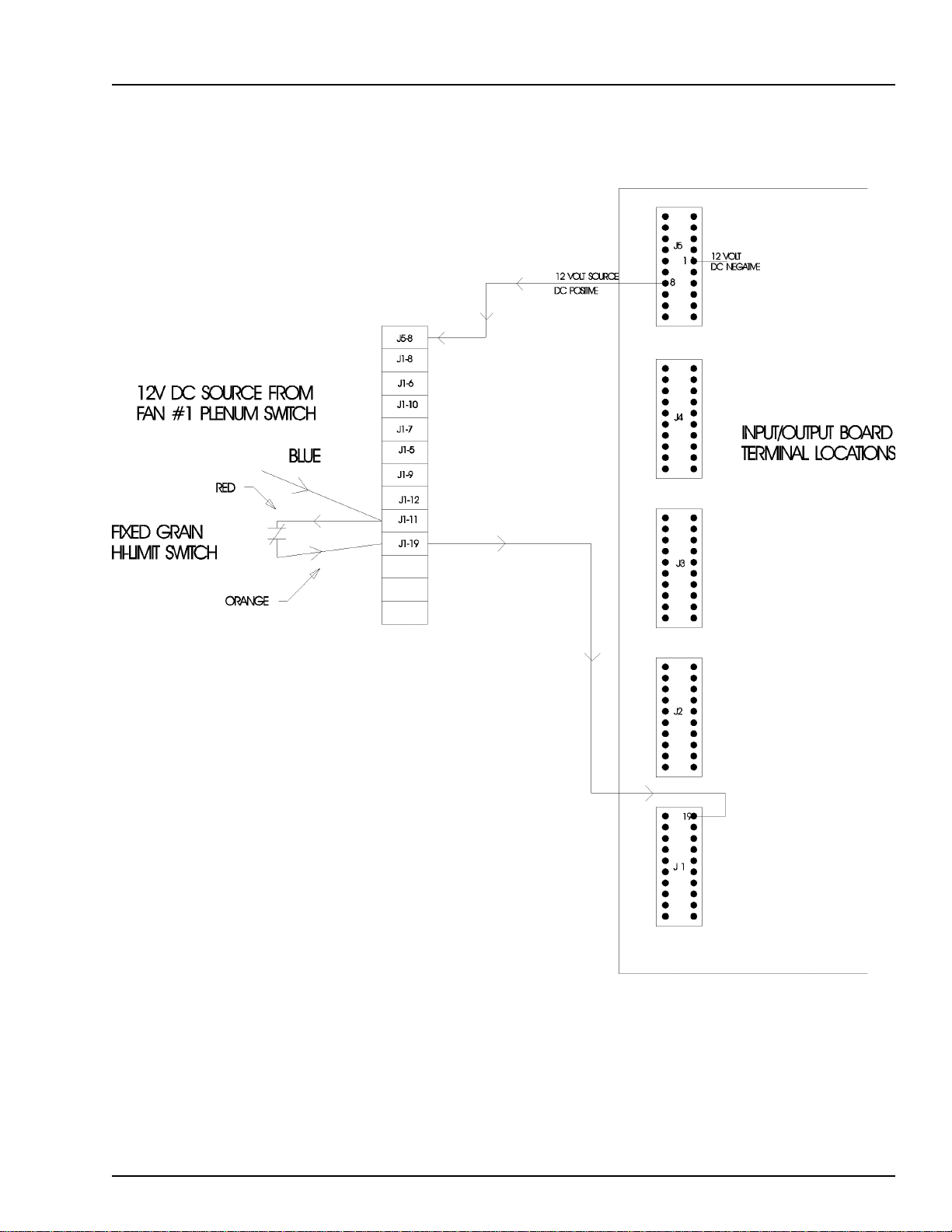
Fixed Grain Hi-Limit
Wiring Reference
23
Page 25
Wiring Reference
LOAD
MOTOR
Portable Dryer Troubleshooting
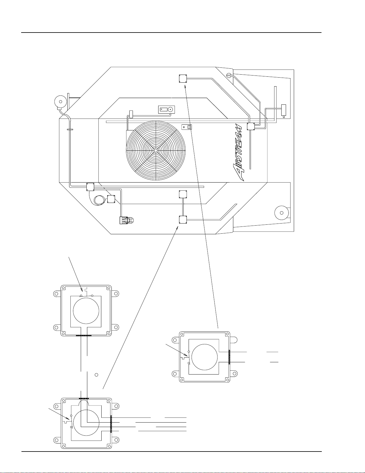
Grain & Plenum Hi-Limit Locations
LIMIT
GRAIN HIGH
LEFT FIXED
TEMP. SENSORS
GAS PIPE TRAIN
11XX
BOX
UPPER
JUNCTION
OUTSIDE LIGHT
LOAD MERCURY SWITCH
PLENUM HIGH LIMIT SWITCH
D03-0004 300 DEGREE
SOLENOID
BURNER
HI-LOW
THERMO
PLENUM
LIMIT
GRAIN HIGH
RIGHT FIXED
TEMP. SENSORS
AIR SWITCH
FAN
BOX
LOWER
JUNCTION
SCR
MOTOR
UNLOAD
24
BLUE J1-11
YELLOW J1-05
RIGHT GRAIN HIGH LIMIT SWITCH
D03-0005 210 DEGREE
BLUE J1-11
YELLOW J1-05
ORANGE J4-19
LEFT GRAIN HIGH LIMIT SWITCH
D03-0005 210 DEGREE
RED J5-05
TO UPPER CONTROL BOX
RED J1-11
ORANGE J1-19
TO LOWER JUNCTION BOX
Page 26
Portable Dryer Troubleshooting
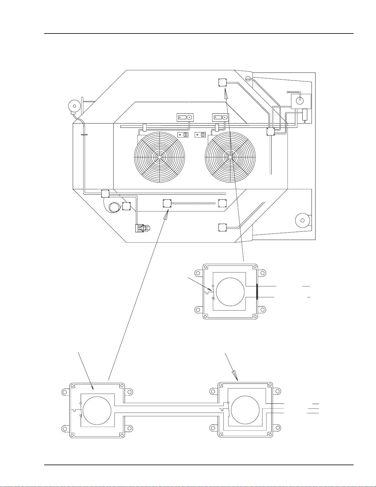
Two Fan Plenum and Grain Limit Switch Wiring
LOAD
MOTOR
FIXED GRAIN
HI-LIMIT AND
THERMO SENSORS
Wiring Reference
MAXON
12XX
BOX
UPPER
JUNCTION
SOLENOID
LOAD MERCURY SWITCH
OUTSIDE LIGHT
BURNER #2
PLENUM #2
HI-LOW
THERMO
HI-LOW
BURNER #1
AIR
SWITCHES
FAN #2
THERMO
SOLENOID
PLENUM #1
LIMIT
ADJUSTABLE
GRAIN HIGH
TEMP. SENSORS
FAN #1
RED TO J1-11
SCR
MOTOR
UNLOAD
2FNLMTSW98.PRT REV. DATE 4/5/98
FAN #2
PLENUM HIGH LIMIT SWITCH
D03-0004 300 DEGREE
FIXED GRAIN HIGH LIMIT SWITCH
D03-0005 210 DEGREE
FAN #1
PLENUM HIGH LIMIT SWITCH
D03-0004 300 DEGREE
ORANGE TO J1-19
YELLOW TO J1-12
BLUE TO J1-11
RED TO J1-05
TO LOWER JUNCTION BOX
25
Page 27
Wiring Reference
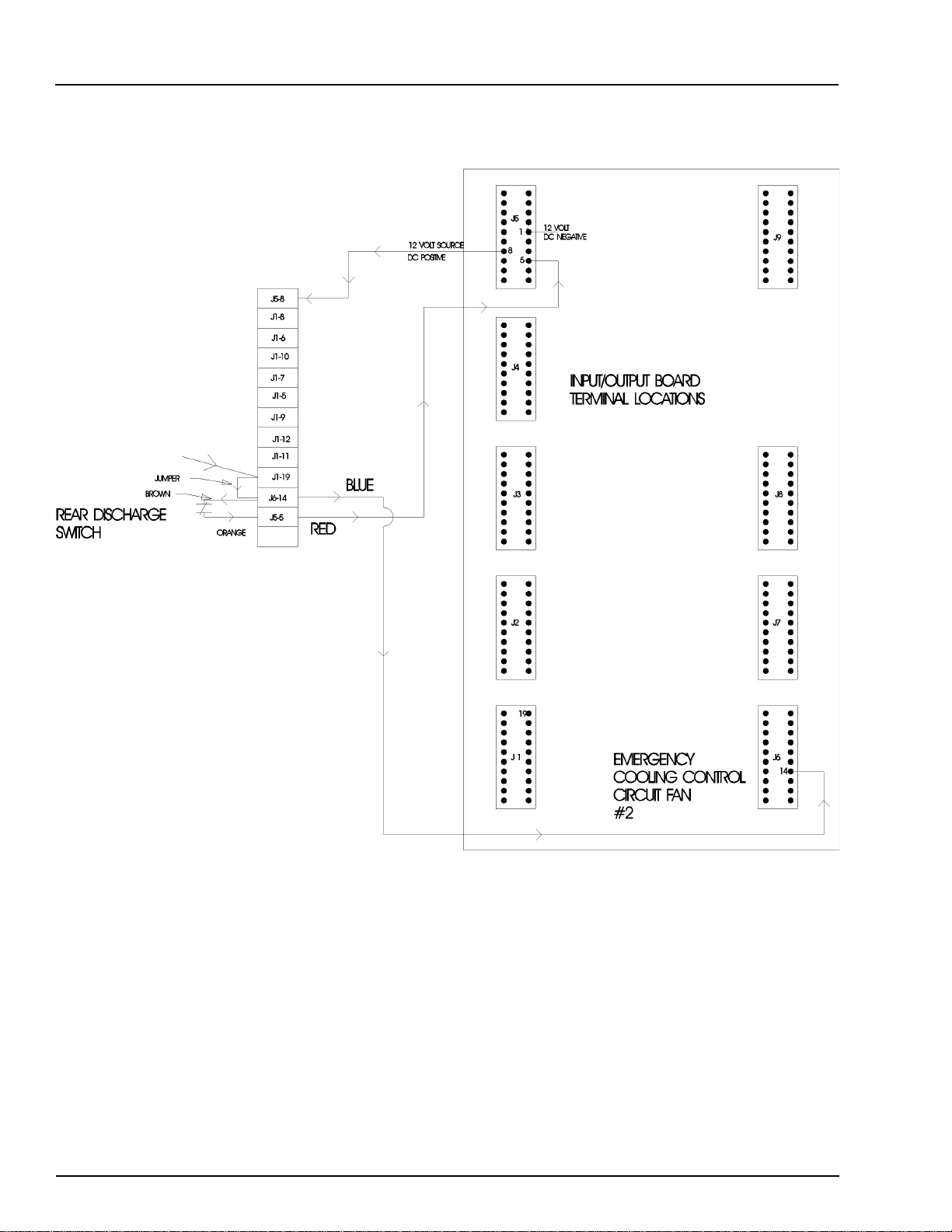
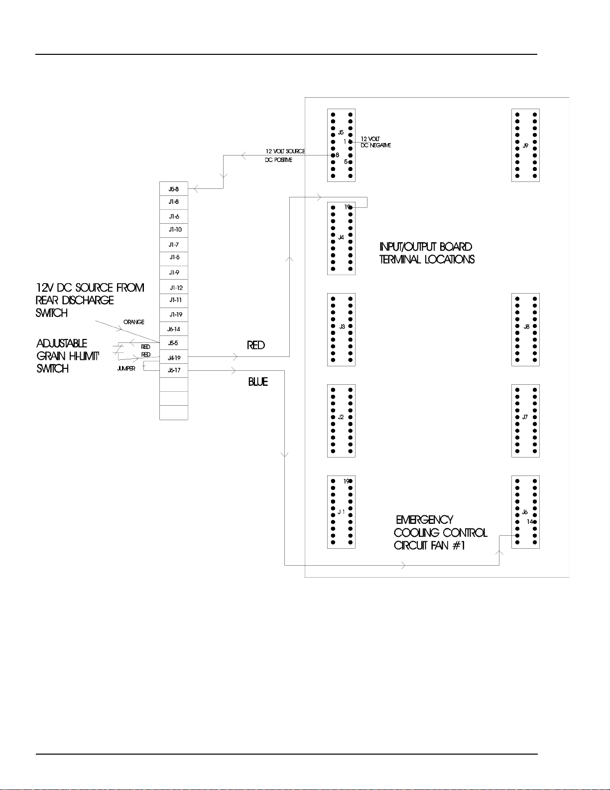
Rear Discharge & Emergency Cooling Circuit
Portable Dryer Troubleshooting
26
Page 28
Portable Dryer Troubleshooting
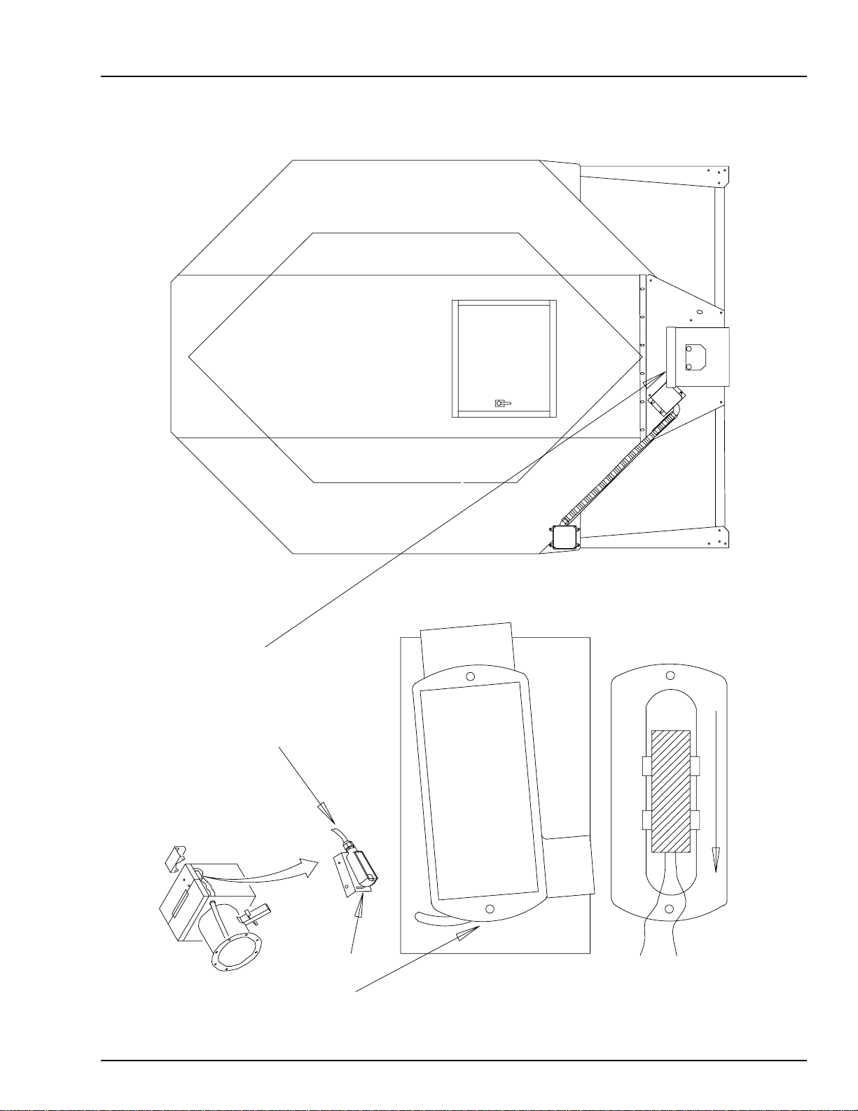
Rear Discharge Mercury Switch
Wiring Reference
POSITIONED WITH LID CLOSED AND
SJOW 18/2 CORD POINTED TOWARDS
THE FRONT OF THE DRYER CONNECT
INSIDE METER ROLL BOX TO BROWN
AND ORANGE WIRES.
LOOSEN SCREWS ON BRACKET
TO CHANGE SENSITIVITY
OF REAR DISCHARGE SWITCH
CONNECT TO SJOW CORD
INSIDE LRL BOX
27
Page 29
Wiring Reference
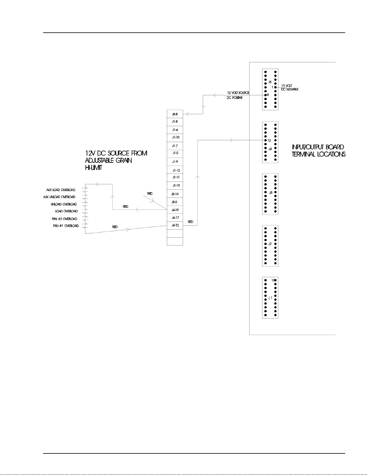
Adjustable Hi-Limit & Emergency Cooling Circuit
Portable Dryer Troubleshooting
28
Page 30
Portable Dryer Troubleshooting
Wiring Reference
Motor Overloads
29
Page 31

D
S
Wiring Reference
12V DC SOURCE FROM
MOTOR OVERLOADS
FAN #2 PRESSURE SWITCH
FAN #1 PRESSURE SWITCH
Air Pressure Switch
J5-8
J1-8
J1-6
J1-10
J1-7
J1-5
J1-9
J1-12
J1-11
J1-19
J6-14
J5-5
J4-19
BLUE
BLUE
J6-17
J4-12
J1-14
J1-13
BLUE
BLUE
Portable Dryer Troubleshooting
J5
12 VOLT
1 1
12 VOLT SOURCE
DC POSITIVE
DC NEGATIVE
8
12
J4
INPUT/OUTPUT BOAR
TERMINAL LOCATION
J3
J2
PRESSURE SWITCH SAFETY
CIRCUIT
14
13
J 1
30
Page 32

Portable Dryer Troubleshooting
Air Pressure Switch Drawing
LOAD
MOTOR
LIMIT
LEFT FIXED
GRAIN HIGH
TEMP. SENSORS
Wiring Reference
GAS PIPE TRAIN
11XX
BOX
UPPER
JUNCTION
SOLENOID
LOAD MERCURY SWITCH
OUTSIDE LIGHT
PLENUM
LIMIT
GRAIN HIGH
RIGHT FIXED
TEMP. SENSORS
AIR SWITCH
FAN
BOX
LOWER
JUNCTION
SCR
MOTOR
UNLOAD
TO UPPER CONTROL BOX
BLUE J5-08 12VDC POSITIVE
BLUE J1-13 AIRFLOW (N.O.)
CALIBRATED WITH
DIAPHRAGM VERTICAL
C N.C. N.O.
HIGH
BACKVIEW OF AIR SWITCH ASSEMBLY
31
Page 33

Wiring Reference
Portable Dryer Troubleshooting
Out of Grain Safety Circuit
32
Page 34

Portable Dryer Troubleshooting
Out of Grain Safety Circuit Location
LOAD
MOTOR
LIMIT
GRAIN HIGH
LEFT FIXED
TEMP. SENSORS
Wiring Reference
GAS PIPE TRAIN
11XX
BOX
UPPER
JUNCTION
SOLENOID
LOAD MERCURY SWITCH
OUTSIDE LIGHT
BURNER
THERMO
HI-LOW
PLENUM
LIMIT
GRAIN HIGH
RIGHT FIXED
TEMP. SENSORS
AIR SWITCH
FAN
BOX
LOWER
JUNCTION
SCR
MOTOR
UNLOAD
LEADS MUST BE IN THIS POSITION
FOR PROPER OPERATION
SJOW 18/2 WIRE
EXITS THROUGH
BLACK
BOX COVER
WHITE
FRONT VIEW OF OPEN BOX
UP
REMOVE THESE EARS
33
Page 35

Wiring Reference
LOAD
MOTOR
Portable Dryer Troubleshooting
Upper Junction Box Drawing
LIMIT
GRAIN HIGH
LEFT FIXED
TEMP. SENSORS
GAS PIPE TRAIN
11XX
BOX
UPPER
JUNCTION
SOLENOID
OUTSIDE LIGHT
LOAD MERCURY SWITCH
BURNER
HI-LOW
THERMO
PLENUM
LIMIT
GRAIN HIGH
RIGHT FIXED
TEMP. SENSORS
AIR SWITCH
FAN
BOX
LOWER
JUNCTION
SCR
MOTOR
UNLOAD
34
BLACK
WHITE
TO LOAD MERCURY SWITCH
WHITE
RED
J9-03
BLACK
L1
BLACK
WHITE
TO 12VDC J5-09
BLACK
J5-04
TO UPPER CONTROL BOX
TO OUTSIDE LIGHT FIXTURE
Page 36

Portable Dryer Troubleshooting
Wiring Reference
Meter Roll Sensor
RIGHT METER
ROLL SENSOR
RED
BLACK
BLUE
J5-19
J5-12
J5-09
NOTE:
RIGHT SENSOR IS
NO LONGER USED ON
DRYERS MANUFACTURED
AFTER MARCH 1, 1997
RED 12VDC POS
BLACK OR WHITE/BLACK STRIP 12VDC NEG
YELLOW LEFT METER PULSE RETURN
BLUE RIGHT METER PULSE RETURN
J5-19
J5-12
YELLOW
BLACK
LEFT METER
ORANGE REAR DISCHARGE RETURN
ROLL SENSOR
BROWN 12VDC TO DISCHARGE SWITCH
TO REAR
ORANGE
J5-09
RED
BROWN
J5-16
JUNCTION BOX
TO REAR DISCHARGE SWITCH
J1-19
J5-05
35
Page 37

Wiring Reference
Portable Dryer Troubleshooting
Meter Roll Sensor Wiring
19
9
J5
16
12
J5-8
J1-7
J1-5
J1-9
J1-11
J1-19
J5-5
J4-19
J4
J1-13
J4-12
J9-16
J7-4
J3
J5-16
J5-19
J5-4
J7-8
J7-3
B1
J5-9
J1-20
J5-12
J2
S1
S2
J 1
Pulse
12 Volt +
12 Volt -
Pulse
Board
Meter Roll
Board
Meter Roll
36
T-2
T-1
T-3
METER ROLL SENSOR
12 Volt +
T-1
12 Volt -
T-2
T-3
1997 Dryers have only 1 meter roll board.
Remove one meter roll board and tie the
2 T-3 wires together.
Page 38

Portable Dryer Troubleshooting
Meter Roll Reversing
Wiring Reference
YOU MUST ENTER INTO THE DRYER
PARMETER MODE BY PRESSING THE
INCREASE AND DECREASE BUTTONS
SIMULTANIOUSLY. YOU WILL HAVE
THE FOLLOWING OPTIONS LISTED:
SHUTDOWN HISTORY (PRESS ENTER)
DRYER MODEL # (IE. 1112)
FAN DELAY (DEFAULT = 5)
FILL AUGER (DEFAULT = END)
BPH FACTOR (DEFAULT = 1.0)
TEST METER ROLL (DEFAULT = YES)
TEST AIR SWITCH (DEFAULT = YES)
M.R. REVERSE (DEFAULT = NO) <- CHANGE TO YES
* REVERSE DELAY (DEFAULT = 60)
* REVERSE TIME (DEFAULT = 1)
* DISPLAYED ONLY IF M.R. REVERSE
IS CHANGED TO YES
REVERSE DELAY = METER ROLLS NORMAL ROTATION TIME
(AMOUNT OF TIME METER ROLLS WILL OPERATE BEFORE
THEY WILL BEGIN REVERSE ROTATION)
REVERSE TIME = METER ROLLS REVERSE ROTATION TIME
(AMOUNT OF TIME METER ROLLS WILL OPERATE IN THE
REVERSED ROTATION MODE)
EXAMPLE: REVERSE DELAY = 10 MINUTES
REVERSE TIME = 1 MINUTE
NOTE:
WHEN INSTALLING RELAY
BASE NOTE POSITION OF
SLOTS FOR RELAY!!
ORANGE
TO
SCR DRIVE
BOARD
A+
85
4
A-
PURPLE
JUMPER WIRES SHOULD
GO BETWEEN:
TERMINALS 4 AND 5
TERMINALS 1 AND 8
1
LOCATE THE ORANGE AND
PURPLE WIRES COMING FROM
THE SCR DRIVE BOARD GOING
TO THE TERMINAL STRIP AND
INSERT THE RELAY AS SHOWN
BLACK
J7-17
(110 VAC CONTROL)
PURPLE
IMPORTANT
YOU MUST ADD A JUMPER WIRE
FROM J9-09 TO J7-16 IN THE
LOWER CONTROL BOX.
14
12
A-
TO
DC DRIVE
MOTOR
13
9
(110 VAC NEUTRAL)
ORANGE
A+
WHITE
J8-20
37
Page 39

Wiring Reference
LOAD
MOTOR
Portable Dryer Troubleshooting
Lower Junction Box Wiring
LIMIT
GRAIN HIGH
LEFT FIXED
TEMP. SENSORS
GAS PIPE TRAIN
11XX
BOX
UPPER
JUNCTION
SOLENOID
LOAD MERCURY SWITCH
OUTSIDE LIGHT
WHITE S1
RED J1-11
BURNER
HI-LOW
THERMO
PLENUM
LIMIT
GRAIN HIGH
RIGHT FIXED
TEMP. SENSORS
AIR SWITCH
FAN
BOX
LOWER
JUNCTION
SCR
MOTOR
UNLOAD
38
TO LEFT FIXED
GRAIN HIGH LIMIT
AND TEMPERATURE
SENSORS
SJOW 18/2 WIRE
BLACK TO MAXON
PURPLE J7-03
WHITE TO MAXON
WHITE J7-08
NATURAL GAS DRYERS ONLY
WIRES GO TO UPPER
CONTROL BOX
BLACK S2
ORANGE J1-19
RED FROM J5-09 TO 12VDC POSITIVE TERMINAL ON METER ROLL SENSOR
BLACK FROM J5-12 TO 12V NEGATIVE TERMINAL ON METER ROLL SENSOR
YELLOW FROM J5-16 TO LEFT METER ROLL SENSOR
BLUE FROM J5-19 TO RIGHT METER ROLL SENSOR
BROWN FROM J1-19 TO DISCHARGE SWITCH
ORANGE FROM J5-05 TO DISCHARGE SWITCH
RED 16 GA. A+ TO SCR DRIVE MOTOR
BLACK 16 GA. A- TO SCR DRIVE MOTOR
GREEN 16 GA. TO SCR DRIVE GROUND
TO SCR
DRIVE MOTOR
TO REAR
OF DRYER
Page 40

Portable Dryer Troubleshooting
Wiring Reference
New Fenwal Board Wiring
The B. GND terminal is used to ground the burner and to complete the flame current signal circuit. This terminal is
new for systems that used the older version of the Fenwal board. This terminal must be connected to the burner
(chassis) ground not only to ensure the best, long term, stable flame signal, but also to ground the burner for
proper sparking.
The use of a burner ground terminal eliminates the problem of loss of flame sense signal due to a missing or loose
neutral or ground (green) wire at the 120 V AC power source. The new board has been designed such that reversing
the polarity of the 120 V AC line does not cause a loss of flame signal. Thus providing a more reliable flame signal
along with a reduction of nuisance lockouts, due to its design and the use of the B. GND terminal.
NEU.
HOT
BURNER
120
VAC
H.V.
S1
B. GND
L1
V2
L2
GAS
VALVE
BURNER
HOT
NEU.
120
VAC
S1
E2
L2
V2
(A) L1
(B) V1
H.V.
E1
GAS
VALVE
V1
NC
Old version with Remote Flame Sense.
New version with Remote Sense using existing
spark and remote sense electrodes.
Note that terminal E2 on the old version has been replaced by terminal B.GND on the new board.
IGNITOR
Part No. HF-4624
Flame Safety Board
BURNER
GROUND
(B. GND)
FLAME ROD
39
Page 41

Wiring Reference
Portable Dryer Troubleshooting
Fenwal Board Troubleshooting
On-Board Diagnostics
The LED will flash on for 0.2 seconds then off for 0.2 seconds to indicate an error condition.
The pause time between error codes will be 2.5 to 3.0 seconds. During power-up, the LED will light
for one second and then turn off to indicate normal operation.
LED Indication Fault Mode
Steady on Internal Control Failure
2 Flashes Flame Fault**
3 Flashes Ignition Lockout Fault
** May indicate either that a flame was detected during
pre- or post-purge, or that there is a flame sensing error.
If a lockout occurs, the board will have to be reset
by shutting off the power to the board.
Measure Flame Current
Micro Amp Meter
BURNER
YES NO
BURNER
Flame
Test
S1
Flame
Test
S1
+
-
FC+
FC-
BURNER
NO
40
Page 42

Portable Dryer Troubleshooting
Flame Control Circuit
TER. 6-8 (110 VOLTS AC)
6
7
8
WHT
OR
TER. 1-5 (12 VOLTS DC)
2
3
4
5
OR
OR
1
WHT
OR
BRN
WHT
Coil
BRN
COIL
COMMON
BLK
Normal Closed
Wiring Reference
COMMON
OR
OR
BLK
Coil
Neutral
WHT
Normal Closed
FLAME
SENSOR
IGNITOR
TIME
DELAY
S1
FENWAL BOARD
E2
L2
V2
L1
V1
WHT
Neutral
WHT
WHT
BLK
BRN
BLK
BRN
WHT
120 VOLTS AC
NEUTRAL
120 VOLTS AC
BURNER LIGHT
OR
OR
12 VOLTS DC
20 SEC SAFETY
20 SEC INPUT
MAIN CONTROL BOX
ALL WIRES COME FROM
41
Page 43

Wiring Reference
Fan Burner Circuit for Canadian Models Only
* MERCOID TERMINALS
J4-20 FOR 1 FAN DRYERS
J4-18 FOR 2 FAN DRYERS
SOLENOIDS
HIGH
BROWN
VAPOR
o
HONEYWELL THERMOSTAT
PART# D03-0047
t
RB
LOW
Portable Dryer Troubleshooting
HOUSING
GREY BROWN
FLAME
SENSOR
MERCOID
SWITCH
WIRING
TIME
DELAY
BLACK
LIQUID
WHITE
BROWN
8
9
WHT
BLK
TER. 1-7 (12 VOLTS DC)
TER. 8-10 (110 VOLTS AC)
BLK
L1 BURNER
L2
WHITE
V2
BROWN
YELLOW
YELLOW
BLACK
PURPLE
PURPLE
7654321
ORG
YEL
BRN
PUR
PUR
VAPOR LIMIT
ORG
RED
RED
YEL
ORG
ORG
12 VOLTS DC
20 SEC INPUT
20 SEC SAFETY
HOUSING LIMIT
PNK
MERCOID SAFETY PNK
ORG
ORG
MERCOID SAFETY
RELAY
GREY
WHITE
BROWN
ORG
BLK
ORG
WHITE WHITE
BLACK
42
IGNITOR
E2 S1
FENWAL PART# HF-4624
E1
110 VOLTS AC
110 VOLTS AC
NEUTRAL- - - - WHT
TO BURNER CIRCUIT
L1V1
BURNER LIGHT - BRN
BLK
BRN
N/C
N/O
COM
MERCOID
PRESSURE SWITCH
SWITCH CLOSES WHEN
BROWN
PRESSURE IS SENSED
Page 44

Portable Dryer Troubleshooting
Conversion Diagram For C Series Dryers To A Switchable
Hi/Low Burner Or A On/Off Burner
Wiring Reference
43
Page 45

Wiring Reference
Portable Dryer Troubleshooting
Fan 28 LP Hi/Low-On/Off
44
Page 46

Portable Dryer Troubleshooting
Fan 28 LP Hi/Low-On/Off Burner With Mercoid
Wiring Reference
45
Page 47

Wiring Reference
Portable Dryer Troubleshooting
Fan 28 NG Hi/Low-On/Off
46
Page 48

Portable Dryer Troubleshooting
Fan 28 NG Hi/Low-On/Off Burner With Mercoid
Wiring Reference
47
Page 49

Wiring Reference
Portable Dryer Troubleshooting
Fan 42 LP Hi/Low-On/Off
48
Page 50

Portable Dryer Troubleshooting
Fan 42 LP Hi/Low-On/Off Burner With Mercoid
Wiring Reference
49
Page 51

Wiring Reference
Portable Dryer Troubleshooting
Fan 42 NG Hi/Low-On/Off
50
Page 52

Portable Dryer Troubleshooting
Fan 42 NG Hi/Low-On/Off Burner With Mercoid
Wiring Reference
51
Page 53

Wiring Reference
Portable Dryer Troubleshooting
SCR Drive Circuit
To Coil
BLK
SCR
CONTACTOR
T2 L2
6
8
A2 A1
COIL
BLK
1
2
3
F +
F L 1
L 2
A +
A -
L 1
L 2
Fuse
220 Volt
L1T1
5
7
OR
S C R Board
52
OR
P
P
W
J6-1
SCR 2
J8-10
J8-20
SCR P2
SCR P1
SCR POWER
SCR NEUTRAL
P
J6-4
SCR P3
To SCR Drive Motor
OR
PUR
A -
A +
TO TERMINAL ON
WITH POWER WIRES
UPPER POWER STRIP
Page 54

Portable Dryer Troubleshooting
RTD Temperature Sensor
LOAD
MOTOR
LIMIT
GRAIN HIGH
LEFT FIXED
TEMP. SENSORS
Wiring Reference
GAS PIPE TRAIN
11XX
BOX
UPPER
JUNCTION
SOLENOID
OUTSIDE LIGHT
LOAD MERCURY SWITCH
BLACK S2
WHITE S1
BURNER
HI-LOW
THERMO
PLENUM
LIMIT
GRAIN HIGH
RIGHT FIXED
TEMP. SENSORS
TO UPPER CONTROL BOX
AIR SWITCH
FAN
BOX
LOWER
JUNCTION
BLACK S2
SCR
MOTOR
UNLOAD
WHITE S1
TO LOWER JUNCTIONL BOX
BLACK 20 GA.
WHITE 20 GA.
FRONT
INSIDE GRAIN COLUMN CONDUIT
SOLDERED AND INSULATED INSIDE CONDUIT
REAR
BLACK 20 GA.
WHITE 20 GA.
FRONT
INSIDE GRAIN COLUMN CONDUIT
SOLDERED AND INSULATED INSIDE CONDUIT
REAR
53
Page 55

)
Wiring Reference
USING OHM METER BEGIN CHECKING
THE SENSORS FOLLOWING FIG. 1
Portable Dryer Troubleshooting
Test Procedure for E.M.C.S. Dryers
IF OHMS DOES NOT = 3.4 K
CHECK LOWER AND UPPER TERMINAL
STRIP (ON SINGLE MODULES CHECK S1 & S2
(ON DOUBLE OR TRIPLE MODULES
CHECK J6-9 TO J6-6 = 3.4 AND
CHECK J6-11 TO J6-8 = 3.4)
IF MEASUREMENTS DO NOT = 3.4 K
CHECK CONNECTIONS IN WHITE
JUNCTION BOX ON FAR LEFT AND
RIGHT SIDES FACING THE FAN END.
IF NONE OF THE MEASUREMENTS = 3.4 K,
THEN CHECK EACH INDIVIDUAL SENSOR.
FIG.1
J5-3
4
E.M.C.S. PORTABLE DRYERS
5
6
CONTROL
MOISTURE
THERMOSTAT
9
8
7
3
2
1
S2
S1
3.4 ON 20K
SCALE AT
70 DEGREES
54
Page 56

Portable Dryer Troubleshooting
Temperature Charts
We use two (2) different types of sensors (NTC thermistor on the Competitor Series 2000, and an
encapsulated sensor on the E.M.C.S dryer) in our dryers. The resistance of the sensors varies according to the
outside temperature. For example, on the E.M.C.S. dryers, for every one (1) degree rise in temperature the
resistance increases 4.8 ohms. However, on the Competitor Series 2000 dryer , the sensor reacts just the opposite,
the resistance rises with colder temperatures. The charts displayed above will help when troubleshooting any
sensor problems.
55
Page 57

Troubleshooting Tips
Portable Dryer Troubleshooting
DC Drive Metering Roll System
Symptoms: Metering Roll will not turn,
dryer shutdown-"Metering Roll Drive Failure"
Metering Roll Operation
• The DC drive system on the portable
dryer is used to control the output of grain
from the dryer. It is adjusted from the
front of the control box using the high and
low metering roll potentiometers. Components used in this circuit are the SCR
contactor, SCR drive board, DC motor/
gear box, and the input/output board from
the Electronic Monitoring Control System.
• All voltage for the drive system comes
from terminals 1-(L1) and 3-(L2) of the
SCR contactor. There should be 220 volts
AC across these two points even if the
unload system is turned off. If this voltage
is zero, check your incoming main power.
in the 2 Speed position. If this is present
then the SCR contactor and input/output board
are okay.
• If 220 volts AC is present across input of
the SCR drive board (L1 and L2) then
check for voltage across the output of the
board. Change your voltmeter to check for
DC voltage at a range above the 200 volt
scale. Put the leads across A+ and A-. The
voltage across these two points will vary
depending on where the speed control potentiometer is turned. Also try turning the potentiometer up and down. The voltage should go
from zero to approximately 180 Volts DC. If
zero voltage is present across the A+ and Aterminal, first try to disconnect the wires from
these two points and then check for DC volts
again. If the voltage returns, suspect a bad
motor or a problem in the wiring to the motor.
If the voltage does not return, suspect a bad
DC drive board.
• When the unload system is turned on you
should be able to observe the SCR
contactor energizing. The power to the
contactor should turn on and off with the
unload switch. You can check for power by
putting an AC voltmeter across terminals
A1 and A2. Across these points you
should read 120 Volts AC. Also on the top
of the contactor you can see a plunger pulling
in whenever the contactor coil gets power. When
the contactor is energized, power is transferred
from terminals L1 and L2 to terminals T1 and
T2. Understand that L1 and L2 are the Input
of the SCR contactor and T1 and T2 are the
Output of the contactor.
Check the SCR Drive Board
• Next if all the above checks out okay, put
your voltmeter across terminal L1and L2 of the
SCR drive board. You should get 220 Volts AC
across these points when the Unload Switch Is
Check the Motor
• The wires attached to A+ and A- go directly to
the DC drive motor on the dryer. You may
remove the top cover of the motor and check
for the same DC voltages mentioned above at
the motor. If the voltage is not present try to
disconnect the wires, then check for DC volts
again. If you do not get any voltage then look
for a broken or loose wire between the motor
and the drive board terminals.
• If the voltage is present suspect the motor
or the gear box. Removing the motor from
the gear box and trying to run the motor only
is one way of narrowing down the problem, or
you may want to remove the chain and see if
the metering rolls are froze up. Using a pipe
wrench is an easy way to try and rotate the
metering rolls.
56
Page 58

Portable Dryer Troubleshooting
Troubleshooting Tips
Fenwal Ignition System
Symptoms: Burner will not light, dryer
shutdown for "Loss of Flame"
Fenwal Ignition Operation
• The Fenwal Ignition System ignites the
Fenwal Ignition Operation
burner and monitors the flame. Once 120
VAC is applied to the Fenwal, the solenoids
are powered up and the transformer begins
ignition through the ignitor. If flame is
sensed during the ignition period (about
4 seconds), the transformer is turned off,
but the solenoids stay on. If no flame is detected after the ignition period, both the solenoids
and transformer lose power and the dryer
begins a shutdown sequence.
• All voltage for the Fenwal Ignition
System is derived from the input/output
board of the Electronic Monitoring
Control System. For ignition to occur:
1. The fan must be turned on.
2. The pressure switch in the plenum
must indicate the fan is operating.
3. The burner switch must be in the
auto or manual position.
4. The dryer must go through a 10
second purge delay, which is indicated
ing
on the LCD screen.
These steps must take place before troubleshooting
of the Fenwal System can occur. The following
assumes the above steps have been taken.
Fenwal Troubleshooting
• The Fenwal Board located in the fan can
control box on the dryer has seven(7)
terminals. They are L1, L2, V1, V2, S1, S2
and E2. L1 and L2 are considered the input
to the board. After the 10 second purge delay,
an AC voltmeter connected Across L1 and
L2 should read 120 Volts AC. If this is true,
you can assume the input/output board is
operating properly and the problem is in the
Fenwal Ignition System. If no voltage is
present after the 10 second purge delay,
check for voltage going through the auxiliary switch mounted on the side of the fan
contactor for that burner. This switch has
to close before the Fenwal gets power. If
this is OK, check the appropriate output
on the input/output board for that burner.
• If voltage is present across L1 and L2,
check for voltage across the Output of
the Fenwal board. The output terminals
are V1 and V2, and they will also have
120 VAC across them for approximately four(4) seconds. The four(4)
seconds is the amount of time the Fenwal
has to ignite and sense flame or it concludes
no flame is detected and begins a "Loss of
Flame" shutdown. If you have power on the in
put terminals and no voltage on the output terminals, unload the secondary (take the wires off
of V1 and V2) and recheck for voltage. If no
voltage is present then suspect a bad Fenwal
board. If power returns, look for a bad solenoid valve or a problem in the wiring.
Note: All of the above voltage checks can be
bypassed if you can hear one or more of the
solenoids on the gas train snap on after the 10
second purge delay. This is true because the solenoids are connected across V1 and V2, and
for the solenoids to come on, power must be
going through the Fenwal board. Also during
the four(4) second ignition period the transformer is energized and you should be able to
observe sparking across the ignitor. If the solenoids snap, but no ignition takes place, check
for loose ignitor wires or check the ignitor condition/ignition gap
even if flame is sensed the sparking will discontinue after the ignition period (4 seconds).
(1/8 " to 3/16"). Remember
Continued on page 55.
57
Page 59

Troubleshooting Tips
Portable Dryer Troubleshooting
Fenwal Ignition System continued...
Hints
• Hearing the solenoids snap on after the
10 second purge delay means that power
is coming to and through the Fenwal
board. The Fenwal board is probably okay.
• If flame is sensed, the power to the solenoids stays on but the power to the ignitor
always goes off after about four(4) seconds.
• Power to the low pressure solenoid is always on anytime flame is sensed. This is
because the power to the low solenoid is
hooked directly across terminals V1 and
V2 of the Fenwal board.
• Power to the high pressure solenoids is
controlled by the Plenum thermostat. One
side of the solenoid is hooked to V2(neutral)
and the other side is run through the normally closed switch of the thermostat and
then back to V1. This is how the burner is
made to cycle. When the plenum is below
temperature, power is run through the ther
mostat to the high pressure solenoid. When
temperature is reached, the thermostat opens
and the high solenoid loses power.
Ignitor Tips
• Make sure that the ignitors are mounted
correctly through an opening in the burner
skirting. Also, make sure that they are not close
enough to the edges of the opening to cause a
spark to jump the skirting, instead of between
the ignitors.
• Be sure that the ignitor tips are no more than
1/8" apart from each other.
• Make sure that the wire connections on the
ignitors are good and tight.
• On stubborn lighting burners reverse the
direction the ignitor tips are facing. Instead of
having the tips pointing toward the fan or burner,
change the direction so the tips are facing the exhaust end of the dryer. (This is especially true on
burners with no burner cone installed (i.e. Natural Gas).
• L2 and V2 are connected internally in the
Fenwal, and they must be nuetral.
58
Page 60

Portable Dryer Troubleshooting
Troubleshooting Tips
Metering Roll Sensors
Symptoms: No BPH, Total Bushels, RPM dis-
played on LCD or dryer shutdown with metering
roll problems
Metering Roll Sensor Operation
• Each metering roll on the portable dryer
has a sensor mounted to read pulses as
the metering roll is turning. These
pulses are transmitted to the input/output board of the Electronic Monitoring
Control System. The computer interprets this information and then displays
the data on the LCD screen.
• All voltage for the metering roll sensors
is derived from the input/output board
of the Electronic Monitoring Control
System. The sensors are operated with
12 Volts DC from terminals J5-9 and J512 on the board. When checking for volt-
age the negative or black probe (-)of a
voltmeter should always go to terminal
J5-12.
Always use j5-12 for the negaitve anytime you
check for any DC voltage on the dryer.
Then put the red probe (+) of the voltmeter on terminal J5-9. Across these
two points there should be 12 volts DC.
This voltage needs to be checked, but
you can be reasonably assured the 12
volts DC is present if the rest of the dryer
is operating. Check for this voltage on
the terminal strip in the upper control
box.
the incoming 12 volts DC (the T1-+12V and
T2-GND terminals), and one is a pulsing
12 volts DC back to the input/output board
(the T3 out terminal). Checking across T1
and T2 will verify that 12 volts DC is getting
to the sensor.
• The T3 (out) terminal is what delivers
the metering roll information back to
the input/output board in the main control box. The information for the metering roll on the left side of the dryer is
sent on a yellow wire and goes to terminal J5-16. The information for the metering roll on the right side is sent on a
blue wire and goes to terminal J5-19.
• You can use a DC voltmeter to observe
this pulsing voltage. The best place to
check for this voltage is directly on the
input/output board located in the very
back of the lower control box on the
dryer. Check for a pulsing voltage from
J5-16 to J5-12 (negative) and J5-19 to
J5-12 (negative). Across each of these
test points you should be able to observe a pulsing DC voltage when the
metering rolls are turning. You should
be able to speed up or slow down the
pulses by turning the speed of the metering rolls up or down.
Note: Because a digital voltmeter cannot
react fast enough you may not see a full
12 volts DC, instead you may see a pulsing
from zero to about eight(8) volts.
• 12 volts DC is transmitted from J5-8
and J5-12 directly to the metering
roll sensors located on the back of the
dryer. Each of the metering rolls is enclosed in a white plastic box mounted to the
back of the metering rolls. Inside each box
is the metering roll sensor and the metering
roll wheel.
• Each sensor has three(3) wires connected to it. Two(2) of these wires are
Hints
• When checking for a pulsing voltage on
J5-16 or J5-19 you should always leave
the voltmeter across the terminals for
about 30 seconds. Watch the meter
closely. Each pulse should be about the
same length and about the same time
apart. If this is not true, suspect a problem with the sensor on the back of the dryer.
59
Page 61

Troubleshooting Tips
Portable Dryer Troubleshooting
Air Pressure System
• When inspecting the sensor make sure
that the wheel going through the sensor is
positioned in the center and is not touching either side. If the sensor is scratched
it is either bad or will probably go bad.
Airflow Operation
Symptoms: Dryer will indicate a "Loss of Airflow"
• After turning on a fan the computer must
get a signal from the air pressure switch
telling it that the fan is actually running
and the plenum has been pressurized. If
the switch does not show the air pressure
within 20 seconds a "Loss of Airflow"
shutdown occurs.
Troubleshooting: "Loss of Airflow"
driver and turn the adjusting screw counterclockwise. Turning it this way makes
the switch more sensitive to pressure and
will turn on the light easier.
• If adjusting the screw does not solve your
problem consult the layout diagram of the
input/output board. Look for the input for
the problem switch. Example: Fan #1
switch's input is J1-13. This is a 12 volt
DC input and it can be checked with a DC
voltmeter. One of the following conditions
will exist when checking this input.
NO AIR PRESSURE---ZERO VOLTS
HAS AIR PRESSURE---12 VOLTS DC
Remember when checking for 12 volts DC
you should always use one of the DC
negatives for the black probe(-) of your
voltmeter. Some of the terminals that
may be used for the negative(-) are J5-11,
J5-12 or J5-13.
• This error message indicates that the fan
is running and the air pressure in the plenum did not pressurize. First, verify that
the fan is running, and the dryer is full of
grain. There must be grain in the dryer or
no pressure will develop. If the fan does
come on and the dryer is full of grain, but
a "Loss of Airflow" shutdown still occurs,
check the air pressure switch circuit.
• W atching the blue light in the fan switch
is the easiest way to tell if the air pressure switch is sensing air pressure. Each
air pressure switch has a light in the fan
switch that will only come on if air pressure has developed. Turn on the fan and
after it has run up to about one half of its
operating speed the light should go on. If
the fan light is not coming on then the air
pressure circuit is not sensing pressure.
• Try adjusting the air switch on the front
of the plenum to see if it is just out of adjustment. Use a straight blade screw-
• To check fan #1 for air pressure with a
voltmeter:
1. Turn on the dryer.
2. Place the black probe(negative) of
your voltmeter on J5-11 or J5-12.
3. Place the red probe(positive) of your
voltmeter on J1-13. At this point
there should be zero volts here because the fan is not running.
4. Turn on the fan and watch your volt-
meter.
• If the air switch is adjusted properly you
should have zero volts across these test
points when you first turn on the fan. After the fan has run up to about one half of
its normal operating speed you should see
the voltmeter change from zero volts to 12
volts DC. This also works in reverse when
turning off the fan. After the fan is first
turned off, the voltmeter should still show
12 volts DC until the fan has slowed down
to about one half of its operating speed.
This is because even though the fan is
turned off it is still turning and developing some
pressure in the plenum.
60
Page 62

Portable Dryer Troubleshooting
Troubleshooting Tips
• If all the above fails to work then remove
the two wires while blowing into the air
tube. Blowing into the switch is the same as
having air pressure in the plenum. You
should have an open circuit until you blow
into the switch, then it should close. If the
switch does not close try adjusting it, or
replace it with a known good one.
Hints
1. Dryer must be full of grain.
2. Light in the fan switch can be used exactly
like a voltmeter to test.
3. Make adjustments of the pressure in one
quarter turns.
4. Make sure the air tube in the plenum is
not plugged after sitting over the summer.
5. Check the bulb in the fan light. It is a 12
volt bulb.
Vapor High Temperature
Symptoms: Dryer runs for only a short period of
time, then a shutdown occurs.
erature Operation
• This message indicates that the vaporizer on
an LP Dryer is not properly adjusted. LP
(liquified petroleum) must be vaporized
before the burner can operate properly. If
LP is being fed to the dryer it must run
through a vaporizer before it can be burned.
If the vaporizer is getting the fuel too hot it
will cause a Vapor High Limit shutdown.
• The vaporizer is located in the fan/heater
unit. It is wrap of pipe mounted inside the
fan can directly in front of the burner. It
can be seen by looking through the inspection door on the side of the burner.
• T o properly adjust the vaporizer a 1/2"
wrench is needed. Knowing that the gas
can get too hot, you must feel the pipe train
before the regulator to check this temperature. This point may be very hot so be
careful while checking the temperature.
The temperature before the regulator must
be warm to the touch. This point cannot be
hot, nor can it be cold...only warm. Use the
1/2" wrench to loosen the hold down
bracket on the vaporizer. Move the vapor
izer away from the flame to cool down the
pipe train or move it closer to the flame to
make the pipe train warmer.
Troubleshooting: Vapor High
Temperature
• The dryer will shutdown but will probably
restart as soon as the computer is reset.
This is because the high limit is an automatic reset and after the dryer shuts down it
allows the pipe train to cool down.
• After the dryer is reset, it will run from a
few seconds to a few minutes and then
shutdown again. This is because the
Vapor High Limit is heating up again as
61
Page 63

Troubleshooting Tips
Portable Dryer Troubleshooting
soon as the burner is turned on. The
vaporizer must be adjusted to solve this
problem.
Using J5-11 as the negative test point for all voltage
tests, check for 12 volts DC using the following termi-
nals to help diagnose the problem:
Fan #1-J1-5 Fan #2-J1-6
Fan #3-J2-5 Fan #4-J2-6
Fan #5-J3-5 Fan #6-J3-6
Remember that each of these input terminals is part of
the main safety circuit of the dryer, and each must
have 12 volts DC on it before the dryer will operate.
Vapor High Limit Hints
1. Anytime you adjust the Vapor High you
should wait and be sure that the pipe train
temperature stays constant. It may slowly
allow the pipe train to get hotter or colder
the longer the dryer runs.
2. If a dryer is shutting down constantly from
a Vapor High Limit, it may also be caused
from a gas line that is exposed to direct
sunlight. If the fuel line to the dryer is
exposed to direct sunlight, the liquid in
the line will start to vaporize before it
even gets to the dryer. Then, when it runs
through the vaporizer it gets too hot and
causes a shutdown (no matter where you
try and adjust the vaporizer). This problem can be helped by insulating the gas
line from outside heat.
The two wrap has less surface area and it
will not heat the LP quite as much. This
may also be true in colder climates where a
two wrap will not heat up enough. In this
case, the pipe train may develop frost or
even freeze the solenoids open.
4. The Vapor High Limit is an automatic reset
safety device. It will reset itself as soon as
its temperature drops below 190° F. Because the pipe train of the burner cools
down rapidly when there is a dryer shut
down, the V apor High Limit will generally
be cool before the operator gets back to the
dryer. As soon as he hits the stop button to
reset the computer, it comes back up to
normal operation. It appears that the dryer
is shutting down for no apparent reason.
Usually if this happens the dryer will shut
down again a short while after restarting the
dryer.
5. If the LP tank feeding the dryer is getting
very low on fuel, it can also cause the
dryer to shutdown on a Vapor High Limit.
Before adjusting the vaporizer always
check the fuel level in the customers tank.
If the fuel pressure is very low, try suggest
ing that the tank be refilled. Usually this
will solve the problem.
3. In extreme cases the vaporizer may have
to be changed before it will run the proper
temperature. Example: If a dryer has a
burner with a three wrap vaporizer and the
dryer is located in the southern United
States, you may have problems adjusting
thevaporizer far enough from the flame.
In this case, you may have to install a two
wrap vaporizer.
62
Page 64

Portable Dryer Troubleshooting
Troubleshooting Tips
Out Of Grain Warning Shutdown
Out Of Grain Warning
• This message indicated that the dryer has
run low on grain. The shutdown occurs
when the loading equipment has run
longer than the time the operator has set on
the Out of Grain timer. The mercury
switch located on top of the dryer tells the
computer when the dryer is full or calling
for grain. The shutdown usually occurs
when the loading equipment is having
trouble keeping up with the output of the
dryer.
Possible Solution
• Look at the loading equipment to see if this
is the problem. Remember, the top hopper
of the dryer should always have grain in it.
If any of the side screens are opening up at
anytime, then you are losing heat along
with efficiency. This indicates that you are
not filling fast enough. Speed up the
loading equipment to the dryer.
2. Before setting the Out of Grain timer,
monitor how long it takes the dryer to
refill for shrink. Then, set the Out of
Grain timer accordingly . Example: If a
dryer takes six minutes to refill for
shrink, add an additional five minutes to
this, and use this as the amount of time to
program into the Out of Grain timer. The
additional five minutes is to avoid any
nuisance shutdowns. A lot of customers
don't want their fill augers to run empty if
the source of grain runs out. They may
want to set the Out of Grain timer closer
than the additional five minutes. (this is
fine, but caution the customer that it may
cause some nuisance shutdowns.)
3. For the Out of Grain warning to work
properly , the fill equipment must be large
enough to handle the capacity of the
dryer. You do not want the side columns
to get low on grain. This will allow the
airflow to escape from the dryer through
the side screens. If this happens you lose
efficiency and may start having a loss of
airflow shutdown.
• Using J5-11 for the test point ground, test
for 12 volts on J5-4 to test the load mercury
switch. This switch should have 12 volts DC
on it when the dryer is calling for grain and has
zero volts on it when thedryer is full.
Out of Grain Hints
1. The out of grain timer is only in use when
the fill switch is in the auto position. In
the manual position the top mercury
switch will still shut off the fill auger , but
the dryer will not shutdown if the source
of grain to the fill auger is depleted.
63
Page 65

Troubleshooting Tips
Portable Dryer Troubleshooting
Motor Overload Shutdown
This indicates that one of the Motor Overloads
has tripped, shutting down the dryer. Each of the Motor
Overloads is located in the upper main power control
box. They are all wired into a single series circuit that
goes to the input/output board on terminal J4-12. Before the dryer will start terminal J4-12 must have 12
volts DC present, or the Motor Overload shutdown will
occur.
V isually inspect each of the overloads. Y ou can
tell by looking at them if a trip has occurred. Simply
press the reset handle on the overload to reset it. After
resetting the overloads press the stop button to clear the
error.
If no overloads are tripped try the following voltage tests: Using terminal J5-11 as the negative terminal
for all DC voltage checks. Look for 12 volts DC on
terminal J-419. This is the terminal that feeds power to
the Motor Overloads. If the 12 volts DC is present then
check for voltage on J4-12. During a Motor Overload
shutdown J4-12 should have zero volts. If you have
power going to and not returning to J4-12 inspect the
siring from J4-19 to the overloads and then back to J4-
12. If the wiring is okay , turn off all power to the dryer
and do a continuity check from J4-19 to J4-12. This
must be closed circuit to operate properly .
Motor Overload Helpful Hints
1. Each of the Motor Overload is run in a
series circuit. This means, if any of the
Motor Overloads trip, a shutdown will
occur. Visually inspect the overload to tell
which has caused the shutdown.
2. Even though GSI uses ambient compensated overloads, hot weather or positioning
the dryer control box in the sunlight may
cause a Motor Overload shutdown to
occur. This can usually be tested by trying
to run the dryer with the control box door
open a little bit.
3. Each of the overloads has an adjustable
trip setting that can set up to 115 %. At
115% the overload will hold in longer
before it trips.
4. Always check amperages on the motors to
be sure that the problem is not in the
motor itself.
5. Remember that each motor has a built-in
service factor. This allow the motor to
actually run over the rated full load amps.
The motor manufacturers have allowed
GSI, on a number of applications, to run
motors over the full load amp rating. this
is possible because they are being used in
an air over application.
64
Page 66

Portable Dryer Troubleshooting
Competitor Series 2000 Portable
65
Page 67

Competitor Wiring Reference
220 Volt Single (1) Phase Power Drawing
INPUT
MAIN
BREAKER
220V FUSES
SCR
CONTACTOR
3FO
L2
1F0
L1
16GA BLACK
110X0
Portable Dryer Troubleshooting
SCR BOARD ASSEMBLED
D03-0104
KBIC BARRIER TERMINAL BOARD
8 AMP
25 AMP
LINE
FUSE
ACCEL
IR
MIN
MAX
P3 P2P1 I1 F+F- L1 L2
ARM
FUSE
CL
A+ A-
SCR BOARD
RESISTOR
SCR BOARD RESISTOR VALUES
1108-1112 (1/3H.P. 240V) #D03-0039
1114-1126 (3/4H.P. 240V) #D33-0001
AC-1
J6-02
BLOCK
DISTRIBUTION
1FI
3FI
FAN #1
BREAKER
LOADUNLOAD
BREAKER
1FO3F0
FAN #1
CONTACTOR
LOADUNLOAD
CONTACTORCONTACTOR
FAN #1
LOAD
LOAD AUX
UNLOAD
220 VAC INPUT
110 VAC OUTPUT
OVERLOAD
OVERLOAD
OVERLOAD
OVERLOAD
TRANSFORMER
109
MOTOR
TO FAN #1
87
MOTOR
TO LOAD
6
MOTOR
5
TO AUX LOAD
4
MOTOR
3
TO UNLOAD
66
BREAKER
UNLOAD AUX
OVERLOAD
21
MOTOR
TO AUX UNLOAD
Page 68

Portable Dryer Troubleshooting
220 Volt Single (1) Phase Power Drawing (New Version)
Competitor Wiring Reference
67
Page 69

Competitor Wiring Reference
220 Volt Three (3) Phase Power Drawing
MAIN
BREAKER
220V FUSES
120V FUSES
Portable Dryer Troubleshooting
SCR
CONTACTOR
1FO
BLOCK
DISTRIBUTION
110X0
FAN 1 BREAKER
AC1
3FO
FAN #1
CONTACTOR
220 VAC INPUT
110 VAC OUTPUT
FAN #1
OVERLOAD
LOAD
OVERLOAD
TRANSFORMER
AC-1
AC NEUTRAL
15
1413
MOTOR
TO FAN #1
12
1110
MOTOR
TO LOAD
68
LOAD BREAKER
UNLOAD
BREAKER
LOADUNLOAD
CONTACTORCONTACTOR
OVERLOAD
LOAD AUX
UNLOAD
OVERLOAD
OVERLOAD
UNLOAD AUX
987
MOTOR
TO AUX LOAD
6
5
MOTOR
4
TO UNLOAD
321
MOTOR
TO AUX UNLOAD
Page 70

Portable Dryer Troubleshooting
220 Volt Three (3) Phase Power Drawing (New Version)
Competitor Wiring Reference
69
Page 71

Competitor Wiring Reference
Portable Dryer Troubleshooting
COMPETITOR POWER CIRCUIT
( 220 VOL T 1PH )
70
Page 72

Portable Dryer Troubleshooting
COMPETITOR POWER CIRCUIT
( 220 VOL T 3PH )
Competitor Wiring Reference
71
Page 73

Competitor Wiring Reference
Portable Dryer Troubleshooting
COMPETITOR POWER CIRCUIT
( 440 VOL T 3PH )
72
Page 74

Portable Dryer Troubleshooting
Upper Control Box Internal Wiring
Competitor Wiring Reference
USER SAFETY
+12 VDC
HOUSE HI LIMIT
VAPOR HI LIMIT
+12 VDC
LEFT GRAIN HI
RIGHT GRAIN HI
PLENUM HI LIMIT
+12 VDC
REAR DISCHARGE
+12 VDC
OUT OF GRAIN
+12 VDC
MOTOR OVERLOAD
AIRSWITCH N.O.
AIRSWITCH COM.
AIRSWITCH N.C.
FLAME DETECT
FLAME DETECT
PLENUM TEMP
GRAIN/PLENUM
GRAIN TEMP
120 AC NEUTRAL
120 AC POWER
MAIN SOL NEUT
MAIN SOL PWR
CYCLE SOL NEUT
CYCLE SOL PWR
UNLOAD NEUTRAL
UNLOAD POWER
LOAD NEUTRAL
LOAD POWER
FAN NEUTRAL
FAN POWER
IGNITION NEUTRAL
IGNITION POWER
MAXON NEUTRAL
MAXON POWER
SCR CONT NEUTRAL
SCR CONT POWER
SCR P1
SCR P2
SCR P3
WORK LIGHT NEUT
WORK LIGHT PWR
MERCOID SWITCH
USER INSTALLED
USER INSTALLED
USER INSTALLED
USER INSTALLED
J1-17
J7-08
J7-02
J1-13
NONE
NONE
J7-01
J7-03
J7-05
J7-04
J7-09
J7-10
J7-11
J7-19
J7-20
J7-13
J6-02
AC 1
J6-13
M-SOL
J6-15
J6-14
J3-02
J3-01
J3-12
J3-11
J3-14
J6-03
J6-07
J6-06
J3-03
J3-04
J3-18
J6-09
J4-02
SCR2
J4-01
J6-18
LITE
J1-16
UNLD COM
UNLD N/O
LOAD N/O
49
RED
RED
RED
RED
RED
RED
RED
RED
RED
BLU
WHT
BLU
GRY
GRY
YELJ7-12
WHT
ORGJ7-14
WHT
BLK
WHT
BLK
WHT
BLK
W
OR
W
Y
W
BLU
WHT
BLK
WHT
BLK
W
O
P
P
P
WHT
BLK
(CANADA ONLY)
ORG
ORG
YELLOAD COM
YEL
TERMINAL ON
UPPER STRIP
R
R
R
LOAD AUX.UNLOAD AUX.
AC1
J6-02
A+
OR
PUR
A-
R
R
R
R
R
R
R
OVERLOADOVERLOADOVERLOAD
FAN #1LOADUNLOAD
35
ORG
ORG
YEL
YEL
J6-12 (BLK)
COM
N/O
N/C
COM
N/O
N/C
LOADUNLOAD
FAN #1
J3-01
J3-02
J3-12
J6-03
J3-11
J3-14
OR
WHT
YEL
BREAKER BREAKER BREAKER
FAN #1 LOADUNLOAD
WHT
BLU
WHT
DISTRIBUTION
BLOCK
TRANSFORMER
110XO
AC1
BREAKER
3FI
MAIN
1FI
L2
L1
F-F+L1L2A+
A-
321
DRIVE
SCR
CONTACTOR
SCR
3FO
1FO
73
Page 75

Competitor Wiring Reference
Series 2000 Control Box Wiring (New Version)
Portable Dryer Troubleshooting
74
Page 76

Portable Dryer Troubleshooting
Upper Control Box Wiring
Competitor Wiring Reference
220 Volt 1PH
75
Page 77

Competitor Wiring Reference
Portable Dryer Troubleshooting
Upper Control Box Wiring
380, 460 & 575 3PH
76
Page 78

Portable Dryer Troubleshooting
Series 100 Control Box Wiring
Competitor Wiring Reference
2 WIRES 2 WIRES -
16 GA WIRES
1 - END PROTECTOR# D01-0532
48 - COMPRESSION TERM.# D01-0531
2 - ENDSTOP# D01-0533
4 - GROUND TERMINAL# D01-0534
13" DIN RAIL# D03-0013
NO CONNECTION (12VDC CNTR TAP)
+12 VOLTS
HOUSING HIGH LIMIT
VAPOR HIGH LIMIT
+12 VOLTS
LEFT GRAIN HIRIGHT GRAIN HI
PLENUM HIGH LIMIT
+12 VOLTS
REAR DISCHARGE
+12 VOLTS
OUT OF GRAIN
RED
YEL
- - PURP
RED
2 WIRES ORG
2 WIRES RED
- -BLUE
BRN
ORG
BLK
BLK
NO CONNECTION (12 VDC CNTR TAP)
NO CONNECTION
AIRFLOW
AIR GND
2 WIRES WHT/BLK
NO AIRFLOW
FLAME DETECT
FLAME DETECT
PLENUM TEMPERATURE
GRAIN/PLENUM GND
GRAIN TEMPERATURE
BLUE
GRY
ORG
WHT
YEL
WHT/BLK
BLK
NO CONNECTION
NO CONNECTION
MAIN SOLENOID NEUTRAL
MAIN SOLENOID POWER
CYCLE SOLENOID POWER
UNLOAD AUGER NEUTRAL
UNLOAD AUGER POWER
LOAD AUGER NEUTRAL
LOAD AUGER POWER
FAN NEUTRAL
FAN POWER
IGNITION NEUTRAL-----IGNITION POWER
-WHT
BLK
BRN
WHT
BLK
WHT
BLK
WHT
BLK
WHT
BLK
MAXON POWER ---------- PUR
MAXON NEUTRAL -------- WHT
SCR CONTACTOR NEUTRAL
SCR CONTACTOR POWER -
WHT
ORG
METERING ROLL POT BLK
METERING ROLL POT
METERING ROLL POT
WORK LIGHT NEUTRAL
WORK LIGHT POWER
BLK
BLK
WHT
RED
MERCOID SWITCH (CANADA ONLY)
USER INSTALLED
USER INSTALLED
USER INSTALLED
USER INSTALLED
REMOVE SCREW TO ACTIVATE
USER SAFETY TERMINAL
CONNECT WIRE FROM J7-08
THRU USER SAFETY SWITCH
BACK TO USER SAFETY TERM.
RED - - - -J1-17 USER SAFETY
RED - - - -J7-08
RED - - - -J7-02
RED - - - -J1-13
NO CONNECTION (12 VDC CENTER TAP)
NO CONNECTION
NO CONNECTION
RED - - - -J7-01
NO CONNECTION (12 VDC CENTER TAP)
RED - - - -J7-03
NO CONNECTION (12 VDC CENTER TAP)
RED - - - -J7-05
(MOTOR OVERLOAD-49)
RED - - - -J7-04 (MOTOR OVERLOAD-35)
BLUE- - - -J7-09
WHT - - - -J7-10
BLUE- - - -J7-11
GREY- - - -J7-19
WHT - - - -J7-20
YEL - - - -J7-12
WHT - - - -J7-13
ORG - - - -J7-14
WHT - - - -J6-02
BLK - - - -AC-01
WHT - - - -J6-13
BLK - - - -M-SOL
BLK - - - -J6-14
WHT - - - -J3-02
ORG - - - -J3-01
WHT - - - -J3-12
YEL - - - -J3-11
WHT - - - -J3-14
BLUE- - - -J6-03
WHT - - - -J6-07
BLK - - - -J6-06
BLK - - - -J3-03
WHT - - - -J3-04
WHT - - - -J3-18
ORG - - - -J6-09
PUR - - - -J4-02
PUR - - - - SCR2
PUR - - - -J4-01
WHT - - - -J6-18
BLK - - - - LITE
PINK------------ J1-16
ORG - UNLOAD AUX COM
ORG - UNLOAD AUX N/O
YEL - LOAD AUX COM
YEL - LOAD AUX N/O
100STRIP98.PRT REV. DATE 3/12/98
77
Page 79

Competitor Wiring Reference
With Moisture Control Hook Up
Portable Dryer Troubleshooting
Upper T erminal Strip
78
Page 80

Portable Dryer Troubleshooting
With Moisture Control Relay Hook Up
Competitor Wiring Reference
Upper T erminal Strip
79
Page 81

Competitor Wiring Reference
Moisture Manager to Dryer Wiring
Portable Dryer Troubleshooting
(Upper Control Box)
80
Page 82

Portable Dryer Troubleshooting
Input/Output Board & Terminal Strip
Competitor Wiring Reference
J6-1
LINE
CORCOM
LOAD
AC1
J6-02
5VB1
EMI FILTER
J6-02
RED --- J1-17
RED --- J1-13
PNK --- J1-16 - - CANADIAN MODELS ONLY
D03-0181
PNK
RED
20
2
WHT --- J3-04
BLK --- J3-03
ORG --- J3-01
YEL --- J3-11
WHT --- J3-02
RED
19
J1
PUR --- J4-01
PUR --- J4-02
WHT --- J3-18
WHT --- J3-14
WHT --- J3-12
RED
PUR
PUR
1
BLK --- J6-06
BLU --- J6-03
WHT --- J6-13
BLK --- J6-12
ORG --- J6-09
WHT --- J6-07
RED --- J7-03
RED --- J7-02
WHT --- J6-18
WHT --- J6-15
BLK --- J6-14
RED --- J7-01
J2
BLU --- J7-11
WHT/BLK J7-10
BLU --- J7-09
RED --- J7-08
RED --- J7-05
RED --- J7-04
YEL
BLK
BLK --- LITE
WHT --- J7-20
GRY --- J7-19
ORG --- J7-14
WHT/BLK J7-13
YEL --- J7-12
PUR --- SCR2
WHT
WHT
WHT
WHT
WHT
20
2
J4
J3
19
3 AMP FUSE
1
ORG
BLUE-3
BLACK-4
WHITE-6
WIRES
TO DOOR:
RED-2
ORANGE-1
TO I/O BOARD:
RED-6
WHITE-5
YELLOW-1
YELLOW-1
ORANGE-2
GREY-1
BLACK-1
PURPLE-2
WHT/BLK-2
81
Page 83

Competitor Wiring Reference
Portable Dryer Troubleshooting
Competitor Control Circuit
CPU/Display Board
82
Page 84

Portable Dryer Troubleshooting
Competitor Control Circuit
Competitor Wiring Reference
I/O Board
83
Page 85

Competitor Wiring Reference
Portable Dryer Troubleshooting
Competitor Control Circuit
SCR Drive Board
84
Page 86

Portable Dryer Troubleshooting
Competitor Wiring Reference
* The SCR board is located in the
upper control box.
RESISTOR
MIN
MAX
* Terminals L1 and L2 are the input
terminals. When the unload system
is turned on there should be 220
Volts AC accross these terminals.
* Terminals A+ and A- are the ouput
terminals. The voltage across these
terminals is DC and will vary depending on where the speed control potentiometer is set.
* The item circled at the bottom right
of the SCR board in the photograph
is the minimum set potentiometer.
This will be used in the SCR board
set up to set minimum DC voltage.
* The item circled at the bottom left
of the SCR board in the photograph
is the maximum set potentiometer.
This will be used in the SCR board
set up to set maximum DC voltage.
P3 P2 P1 L1 L2 A-A+
IMPORT ANT: After the new board has been installed be sure to remove the resistor
(shown in the photograph above) from the old board and install it in the new board. Just
pull the resistor from the two pin socket and install in the same socket on the new board.
Resistor for 1/3 Hp
Meter Roll motors
used on 12 ft dryers
and shorter . (part
no. D03-0039)
Drying Mode
Switch
Resistor for 3/4 Hp
Meter Roll motors
used on 14 ft dryers
and longer. (part
no. D33-0001)
Control panel switch locations.
Moisture
Control
Switch
Unload
Switch
Metering Roll
Speed (High)
Metering Roll
Speed (Low)
85
Page 87

Competitor Wiring Reference
Setting SCR Board Maximum Voltage
Before starting the procedure set the dryer up as follows:
1. All fan and heater switches to off position and load switch to off position.
2. Control power to on position.
3. Push the dryer power switch.
4. Dryer mode switch to cont. flow position.
5. Moisture control switch to on position.
6. Unload switch to 2 speed position.
Portable Dryer Troubleshooting
1. Set the low metering roll speed to 050 on the dial
indicator shown in the photograph on the left. Set the
high metering roll speed to 999.
Metering Roll
Speed (Low) set to
050
Unload
Switch to 2
speed
position
Metering Roll
Speed (High) set to
999
2. Switch the Unload switch to the 2 speed position.
3. Switch the Moisture Control switch to the off position.
This will put the meter roll rotation speed to the high
setting.
4. Use a voltmeter set at the 200 volt DC range and
probe terminal A+ with the red voltmeter probe and Awith the black voltmeter probe. If the display on your
voltmeter reads 180 volts DC no maximum adjustment
is needed. If your voltmeter does not read 180 VDC,
then use a small screw driver and adjust the max set
petentiometer until the voltage is 180 VDC.
86
A+
MAX
A-
Page 88

Portable Dryer Troubleshooting
Competitor Wiring Reference
Setting SCR Board Minimum Voltage
1. Switch the Moisture Control Switch back to the on position. This will put the meter roll rotation
speed at the low setting.
2. Use a voltmeter set at the 20 volt DC range and probe terminal A+ with the red voltmeter probe
and A- with the black voltmeter probe. Use a small screw driver and adjust the min set potentiometer until the voltage is 9 VDC.
The SCR board is now set and dryer is ready for normal operation at desired settings.
SCR Drive Board (Part No. D03-0104)
MIN
A-A+
87
Page 89

Competitor Wiring Reference
Upper Control Box External Wiring
Portable Dryer Troubleshooting
ORANGE J7-19 FLAME DETECTION TO FLAME PROBE
WHITE J7-20 FLAME DETECTION TO FLAME PROBE BASE
WHITE J6-07 IGNITION TRANSFORMER 120VAC NEUTRAL 16 GA. WIRE
BLACK J6-06 IGNITION TRANSFORMER 120VAC POWER 16 GA. WIRE
BLACK J6-12 MAIN SOLENOID 120VAC POWER
WHITE/BLACK STRIP J7-10 12VDC NEGATIVE
WHITE J6-13 MAIN/CYCLE SOLENOID 120VAC NEUTRAL
BROWN J6-14 CYCLE SOLENOID 120VAC POWER
YELLOW J7-02 FROM HOUSING HIGH LIMIT SWITCH
RED J7-08 12VDC INPUT POWER TO HOUSING & VAPOR HIGH LIMIT SWITCHES
PURPLE J7-13 FROM VAPOR HIGH LIMIT SWITCH
BLUE J7-09 CONNECTS TO AIRSWITCH N.O. TERMINAL
WHITE/BLACK STRIP J7-10 CONNECTS TO AIRSWITCH COMMON TERMINAL
GREY J7-11 CONNECTS TO AIRSWITCH N.C. TERMINAL
TO FAN CONTROL BOX
TO AIRSWITCH ASSEMBLY
WHITE J7-13 PLENUM/GRAIN TEMPERATURE SENSOR COMMON
BLACK J7-14 RIGHT GRAIN TEMPERATURE SENSOR
RED 12VDC TO LEFT GRAIN HIGH LIMIT SWITCH
ORANGE 12VDC FROM LEFT GRAIN HIGH LIMIT SWITCH
PURPLE J3-03 MAXON POWER 120VAC (NATURAL GAS ONLY)
WHITE J3-04 MAXON 120VAC NEUTRAL (NATURAL GAS ONLY)
BROWN 12VDC TO REAR DISCHARGE SWITCH
ORANGE J7-03 FROM REAR DISCHARGE SWITCH
RED 16 GA. A+ SCR DRIVE MOTOR
BLACK 16 GA. A- SCR DRIVE MOTOR
GREEN 16 GA. SCR DRIVE MOTOR GROUND
BLACK 12VDC TO LOAD MERCURY SWITCH
BLACK J7-05 FROM LOAD MERCURY SWITCH
WHITE J6-18 OUTSIDE LIGHT AC NEUTRAL
RED LITE 120VAC OUTSIDE LIGHT POWER
YELLOW J7-12 PLENUM TEMPERATURE SENSOR
WHITE J7-13 PLENUM/GRAIN TEMPERATURE SENSOR COMMON
BLACK J7-14 GRAIN TEMPERATURE SENSOR
BLUE FROM PLENUM HIGH LIMIT SWITCH TO J7-01
RED TO PLENUM HIGH LIMIT SWITCH
ORANGE TO RIGHT GRAIN HIGH LIMIT SWITCH
RED FROM RIGHT GRAIN HIGH LIMIT SWITCH
TO LOWER JUNCTION BOX
TO UPPER JUNCTION BOX
TO PLENUM AND RIGHT
FIXED GRAIN HIGH LIMIT
SWITCHES AND TEMPERATURE
SENSORS
88
Page 90

Portable Dryer Troubleshooting
Input/Output Board 12 Volt
UNLOAD AUGER POWER
MAXON VALVE/DRYER RUNNING LIGHT
PROOF OF FLAME LIGHT
PROOF OF AIRFLOW LIGHT
MOISTURE CONTROL HOLDING LIGHT
LOAD POWER
TRIAC SPARE
N.C. (TIED TO J3-19)
N.C. (TIED TO J3-19)
120V INPUT FROM CPU
120 VOLT AC OUTPUT
J3
2
4
31
68
5
101214161820
19 17 15 13 11 9 7
Competitor Wiring Reference
UNLOAD AUGER NEUTRAL
AC NEUTRAL
AC NEUTRAL
AC NEUTRAL
AC NEUTRAL
LOAD AUGER NEUTRAL
FAN NEUTRAL
AC NEUTRAL
AC NEUTRAL
AC NEUTRAL
J5
J2
J4
3 AMP FUSE
R
E
L
A
Y
2
12 VDC
FAN ON
BURNER ON
UNLOAD 1 SPEED
4
31
68
5
101214161820
LOAD ON
CONTINUOUS FLOW
VAPOR HIGH LIMIT INPUT
SPARE
12 VOLT DC INPUT
USER SAFETY INPUT
12 VDC
19 17 15 13 11 9 7
J1
RL1-A COMMON TO POT INPUT ON SCR BOARD
RL1-B COMMON TO POT INPUT ON SCR BOARD
RL1-B N.C. LOW SPEED POT A
RL1-B N.O. HIGH SPEED POT A
RL1-A N.C. LOW SPEED POT B
RL1-A N.O. HIGH SPEED POT B
12 VDC
FAN AUTO
BURNER AUTO
UNLOAD 2 SPEED
LOAD AUTO
DRYER EMPTY (BATCH ONLY)
MOISTURE CONTROL ON
MERCOID SAFETY INPUT
SPARE
12 VDC
DATA INTERLINK CABLE CONNECTION
THESE JUMPERS MUST BE INSTALLED
J1-1 TO J1-17 - USER SAFETY
J1-1 TO J1-16 - MERCOID SAFETY
89
Page 91

Competitor Wiring Reference
Cpu Board Wiring
MAIN SOL PWR 120VAC
CYCLE SOL PWR 120VAC
RL3 N.C.
NO CONNECTION
RL1 N.C.
AC NEUTRAL INPUT
IGN TRANS PWR 120VAC
Portable Dryer Troubleshooting
SPARE AC OUTPUT
LIGHT AC NEUTRAL
120VAC TO I/O BOARD
FUSE
TRANSFORMER
RS485 COM PORTS
J5
1
N
2
J6
1
3
1
J1
J2
4
FLAME PROBE A
8
6
4
5
3
1
RL1 N.O.
110VAC IN
RL1 COMMON
3
J8
TEMP SENSOR (GROUND)
+ 12VDC OUTPUT
+ 12VDC OUTPUT
14
12
10
9
7
11
N
RL3 COM SCR IN
IGN TRAN NEUTRAL
RL3 N.O. SCR DRIVE OUT
STOP SWITCH
N/C AIRSWITCH (5 VDC)
N/O AIRSWITCH (5 VDC)
N
18
16
20
19
17
15
13
NNN
MAIN SOL NEUTRAL
N
AC NEUTRAL
LOAD COIL NEUTRAL
CYCLE SOL NEUTRAL
110V NEUTRAL
N
OUT OF GRAIN SWITCH
REAR DISCHARGE SWITCH
GRAIN/PLENUM HIGH LIMIT SWITCH
12 VDC GROUND
90
MONITORING
DISPLAY
171513
19
J7
20
FLAME PROBE B
975
11
161412
18
-
+ 12VDC OUTPUT
12VDC NEGATIVE
10
-
GRAIN TEMP SENSOR
PLENUM TEMP SENSOR
AIRSWITCH COM (DC NEG)
321
864
START SWITCH
+12VDC OUTPUT
MOTOR OVERLOAD
HOUSING HI-LIM
-
Page 92

Portable Dryer Troubleshooting
Competitor Wiring Reference
Programing Instructions for Competitor Series Grain Dryers
1. Turn Control Power on dryer to the off position.
2. Locate programming jack (J2) on back of computer . (See next page). There will be a cable plugged into
this jack that comes from the other computer board. Unplug this cable to plug the programmer into the jack.
3. Plug the series 2000 cable into programming jack and into programmers DB-9 jack.
4. Be sure that the rotary switch on the programmer is set to position 8.
5. Turn on Control Power to the dryer .
6. The four (4) lights on the programmer will come on, then three (3) will go out leaving the power light still on.
7. Push the start button on the programmer to start the transfer of Software.
8. The busy light will flash until the transfer process is complete.
9. When completed, the pass light will flash indicating a successful transfer .
10. If the fail light flashes then check your connections and repeat the above process.
11. T urn Control Power on dryer to off and remove the cable.
12. Turn on the dryer and the opening screens should indicate the newer version of software.
91
Page 93

Competitor Wiring Reference
Programmer Hook Up Diagram
Portable Dryer Troubleshooting
J2 CONNECTOR
DB9 JACK
PLUG THIS INTO
FUSE
THE PROGRAMMER
N
2
J6
468
1
3
5
1012141618
7
9
1113151719
N
N
20
N
N
N
N
SERIES 2000 CABLE
PROGRAMMING JACK TO UPDATE
SOFTWARE ON EPROM PLUG
PROGRAMMER INTO THIS JACK
TRANSFORMER
J4
J5
1
87654321
MONITORING
DISPLAY
RS485
COM
PORTS
1
3
1
J1
3
J8
J2
4
DIP SWITCHS
ON
DIP SWITCH #8 = AIR SWITCH TEST ON OR OFF
DIP SWITCH #6 = BURNER CYCLE HI-LO (OFF) OR ON-OFF (ON)
DIP SWITCH #5 = NO LOAD DURING LOW FIRE CYCLE (BATCH ONLY)
DIP SWITCH #7 = EMERGENCY COOLING MODE
J7
19
20
17
18
-
15
16
13
14
11
12
7
9
10
-
123
5
4
6
8
92
Page 94

Portable Dryer Troubleshooting
Competitor Wiring Reference
Programming Instructions Using Palm Pilot
On the Competitor Dryer there is only one board to program. This board is called the CPU
Display board. It is mounted to the door of the lower box. T o access, open the door and the programming jack is located on the back of this board. T o program, follow the instructions below .
1. Turn the control power on the dryer to the off position.
2. Locate the programming jack (J2 connector) on back of board.
3. Unplug the communications cable that is connected to that connector. This is the cable that
runs from the CPU/Display board and IO Board.
4. Connect the DB-9 connector from the Palm Pilot to the series 2000 cable.
5. On the Palm Pilot select the program for that particular board and tap on it.
6. Turn the dryer control power back on.
7. The programming process should begin, it will erase the present program and start the new
program.
8. A screen will come up telling you when the transfer of software is complete.
9. When the process is complete turn dryer control power off, remove the connector from the
board and plug the communications cable back on to the CPU/Display board.
10. Turn on the dryer and the opening screens should indicate the latest version of software.
Refer to next page for more information on programming the Series 2000 board.
If ordering Palm Pilot from GSI there are two kits available:
D03-0692 ( Palm Flash Program Kit Deluxe )
D01-1771 Series 2000 Programming Cable
D03-0688 Palm Pilot IIIC (color)
D03-0694 Palm Pilot Hot Sync Cable
D03-0695 Palm Flash 9 Pin M-M Adapter
D03-0709 Disk, CD-Rom Palm Flash Software
D03-0693 ( Palm Flash Program Kit Economy )
D01-1771 Series 2000 Programming Cable
D03-0689 Palm Pilot M100 (black & white)
D03-0695 Palm Flash 9 Pin M-M Adapter
D03-0709 Disk, CD-Rom Palm Flash Software
93
Page 95

Programming Competitor
Programming Competitor Dryer Using Palm Pilot
Palm Pilot
D03-0689 (M100)
D03-0688 (IIIC)
Portable Dryer Troubleshooting
Hot Sync Cable
D03-0694
DB-9 M-M Ad a p te r
D03-0695
DB-9 Connector
(
Connects to the
DB-9 M-M adapter)
Palm
Side
D ryer
Side
DB-9 Connector
J2 Connector
(
Connects to the back
of CPU/Displa y bo ard)
94
Series 2000 Prog ram min g Cabl e
D01-1771
(Use on CPU/Board)
Page 96

Portable Dryer Troubleshooting
Back of Switch Panel Layout
JUMPERS:
ORANGE-5
BLACK-1
PURPLE-4
BROWN-3
BLUE-3
YELLOW-3
GREY-1
FROM I/O BOARD:
RED J1-16 TO J1-20
RED J3-19 TO J6-16
WHITE J3-04 TO J6-17
BLACK J6-05 TO J6-11
BLACK J6-01 TO J6-05
Competitor Wiring Reference
BK
AC1
BK
LITE
CONNECTS TO
TERMINAL STRIP
ON BACK PANEL
BLACK-1
RED-1
WHITE-1
BLUE-1
TO DISPLAY:
TRANSFORMER
YELLOW-1
FUSE
J6
J5
1
MONITORING
DISPLAY
CONTROL POWER
GY
BATCHCF
TWO POS
OUTSIDE LIGHT
GY
J1-11
J3-03
BLK
DRYING MODE
GY
YL
J1-09J1-10
12
3
3
1
1
J8
J6
19 20
LOAD
YL
J3-11
YL
BL
J1-03
FAN
OR
BL
J1-04
BR
BR
J1-06 J1-05
T
BM
PR
PR
J4-03
J4-05
BL
J3-07
4
J7
1920
CONNECT J6-05
TO J6-01.
1
2
BR
J3-05
J1-08
OR
J3-01
OR
J1-14
MOISTURE CONTROL
OR
J3-09
THREE POS
UNLOAD BURNER
START
M
OR
J1-07
no
com
BK
J3-03
T
B
no
STOP METERING ROLL SPEED
com
J4-06
J4-04
SCR-2
PRPRPR
95
Page 97

Competitor Wiring Reference
Back of Switch Panel Wiring
Portable Dryer Troubleshooting
BLACK
J6-01
FUSE
TRANSFORMER
J5
1
MONITORING
DISPLAY
J6-01 (AC POWER) BLACK
J6-02 (AC NEUTRAL)
WHITE
12
3
3
1
1
J1
J8
4
1920
J7
J6
19 20
1
2
CONTROL POWER
J6-02
BATCHCF
GREY
DRYING MODE
J6-02
LOAD AUGER
FAN
J6-02 J6-2 J6-02
HEATER
OUTSIDE LIGHT
J7-15 J7-15
J7-15
RED
J7-15
96
REQUIRED JUMPERS:
RED J3-19 TO J6-16
WHT J3-04 TO J6-17
BLK J6-01 TO J6-05
WHITE
MOISTURE CONTROL
RED
THREE POS
UNLOAD
START
J7-06
BLU
J7-15
com
J6-02
METERING ROLL SPEED
J6-02
no
STOP
no
com
RED
J7-07
YEL
Page 98

Portable Dryer Troubleshooting
Air Switch Assembly
LOAD
MOTOR
LIMIT
LEFT FIXED
GRAIN HIGH
TEMP. SENSORS
Competitor Wiring Reference
GAS PIPE TRAIN
BOX
UPPER
JUNCTION
1XX
LOAD MERCURY SWITCH
SOLENOID
OUTSIDE LIGHT
PLENUM
LIMIT
GRAIN HIGH
RIGHT FIXED
TEMP. SENSORS
AIR SWITCH
FAN
BOX
LOWER
JUNCTION
SCR
MOTOR
UNLOAD
TO UPPER CONTROL BOX
GREY J7-11 NO AIRFLOW (N.C.)
WHITE/BLACK STRIP J7-10 AIRFLOW GROUND
BLUE J7-09 AIRFLOW (N.O.)
CALIBRATED WITH
DIAPHRAGM VERTICAL
C N.C. N.O.
HIGH
BACKVIEW OF AIR SWITCH ASSEMBLY
97
Page 99

Air Switch Adjustment
Air Switch location.
Portable Dryer Troubleshooting
Competitor Air Switch Adjustment
Air Switch assembly.
IMPORTANT: T o adjust the air switch the grain columns
need to be full of grain so that the plenum can build up air
pressure and close the air switch.
With the Load Auger, Fan, Heater, and Unload switches in the off position turn
1.
on the Control power then push the Dryer Power Start switch.
With power now applied to the dryer flip the fan switch to the on position and
2.
watch the light right above that switch. If the light illuminates when the fan
reaches half its full speed, then no adjustment is required. However, if the light
does not illuminate until the fan is running at full speed or the light does not
illuminate at all and the dryer shuts down the air switch is adjusted too high
(skip to step 3a). If the light illuminates before the fan reaches half its full
speed the air switch is adjusted too low (skip to step 3b
3a.
If the light above the fan switch illuminates after the fan reaches full speed or did not
illuminate at all and the dryer shut down then the air switch needs to be made more
sensitive. Turn adjustment screw in the more sensitive direction (counter clockwise). Make this adjustment on the air switch 1/4 turn at a time and each time restart
the fan and watch to see when the light illuminates.
If the light above the fan switch illuminates before the fan reaches half its full speed
3b.
then the air switch needs to be less sensitive. Turn adjustment screw in the less
sensitive direction (clockwise). Make this adjustment on the air switch 1/4 turn at a
time and each time restart the fan and watch to see when the light illuminates.
4. Flip the fan switch to the off position and watch the light. Now it should go out when
the fan is about half its full speed. Adjust the air switch if necessary . Remember that
less sensitive (clockwise adjustment) will require a higher fan speed to close the air
switch, and more sensitive (counter clockwise adjustment), the switch can close at
a slower fan speed.
).
AUTO
FAN
OFF
ON
98
Page 100

Portable Dryer Troubleshooting
Fixed Grain Hi-Limit & Temperature Sensor
Competitor Wiring Reference
GAS PIPE
TRAIN
LOAD
MOTOR
BOX
UPPER
JUNCTION
1XX
LOAD MERCURY
SWITCH
SOLENOID
OUTSIDE LIGHT
RIGHT FIXED
LEFT FIXED
GRAIN HIGH
LIMIT
GRAIN HIGH
LIMIT
TEMP. SENSORS
FAN
PLENUM
TEMP.
SENSORS
AIR SWITCH
BOX
LOWER
JUNCTION
MAXON
UNLOAD
SCR
MOTOR
TO LEFT FIXED
GRAIN HIGH LIMIT
AND TEMPERATURE
SENSORS
SJOW 18/2 WIRE
BLACK TO MAXON
WHITE TO MAXON
NATURAL GAS DRYERS ONLY
WIRES GO TO UPPER
CONTROL BOX
RED
WHITE J7-13
ORANGE
BLACK J7-14
PURPLE J3-03
WHITE J3-04
BROWN FROM 12VDC TO DISCHARGE SWITCH
ORANGE FROM J7-03 TO DISCHARGE SWITCH
RED 16 GA. A+ TO SCR DRIVE MOTOR
BLACK 16 GA. A- TO SCR DRIVE MOTOR
GREEN 16 GA. TO SCR DRIVE GROUND
TO SCR
DRIVE MOTOR
TO REAR
OF DRYER
99
 Loading...