

Page 1
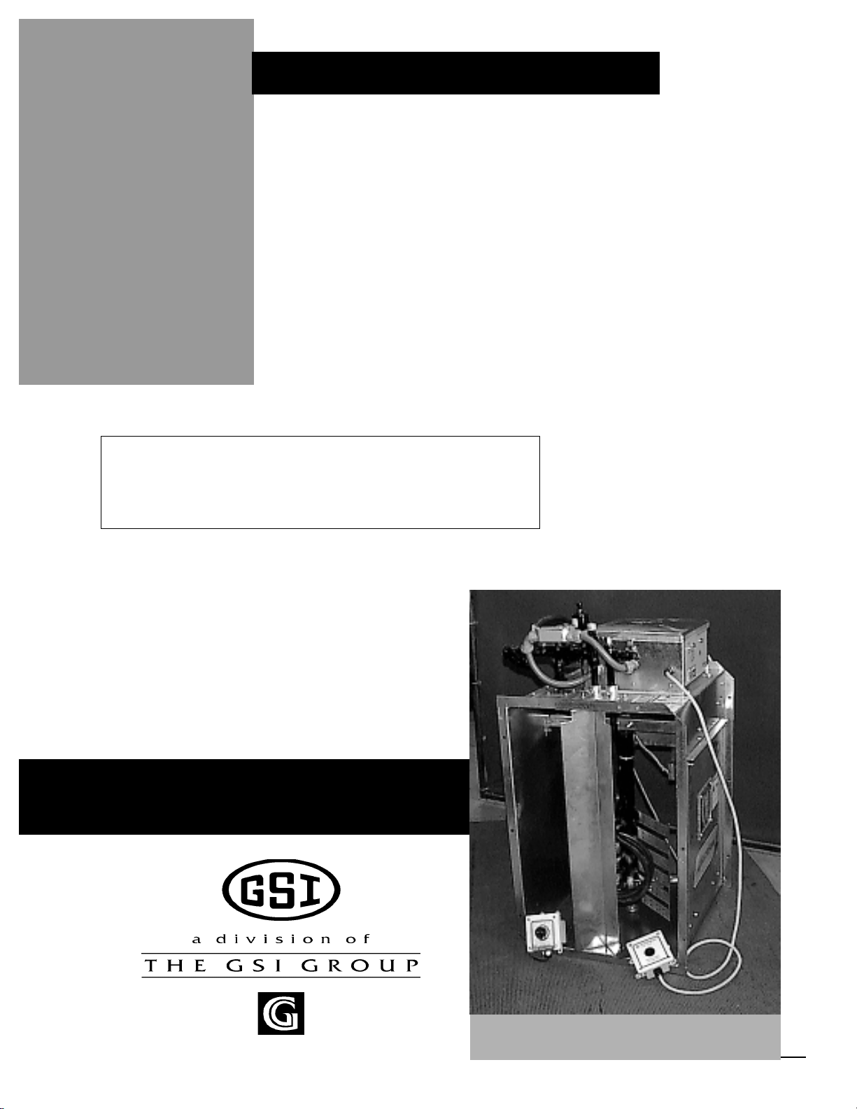
Series 2000 Downwind Heater
Downwind Series 2000
Centrifugal Heater
Installation And
Operating Instructions
MODEL # CH__ - __ __ - __ __ - 2 __ (HIGH)
MODEL # CL__ - __ __ - __ __ - 2 __ (LOW)
Owner's
Manual
PNEG-591
1
Page 2

Series 2000 Downwind Heater
2
Page 3

Series 2000 Downwind Heater
Safety ..........................................................................................................................4
Series 2000 Heater Installation.........................................................................................6
High T emperature Heater Specifications................................................................6
Low T emperature Heater Specifications................................................................6
Air Pressure Switch and T emperature Sensor Box......................................................7
Transition Hi-Limit Installation................................................................................7
Bin Configuration/Operating T emperature T able...................................................8
Heater Unit Wiring..................................................................................................9
Secondary Heater Unit Wiring................................................................................9
Machine T o Earth Ground.....................................................................................10
Proper Installation Of The Ground Rod.................................................................10
Previously Installed Units......................................................................................10
Fuel Connection For Liquid Propane Models.........................................................11
Fuel Connection For Propane V apor Models........................................................1 1
Fuel Connection For Natural Gas Models............................................................11
Installing Optional Humidity Sensor ....................................................................12
Series 2000 Operating Procedure....................................................................................13
Power Up..............................................................................................................13
Normal Operating Displays With Heater Not Running..........................................14
Starting The Dryer.................................................................................................15
Setting Gas Pressure ............................................................................................15
BTU's Per Gauge Pressure (PSI) 10-15 hp Models (Approximate)......................17
BTU's Per Gauge Pressure (PSI) 20-40 hp Models (Approximate).....................18
BTU's Per Gauge Pressure (PSI) Lo-temp Models (Approximate).....................20
Adjusting the Air Pressure Switch.......................................................................21
Adjusting The V aporizor ........................................................................................22
Running The Dryer...............................................................................................22
Programming Set Points.......................................................................................23
Programming Hours T o Shutdown.......................................................................24
Drying Grain In The Hours T o Shutdown Mode...................................................24
Run Hours Display ...............................................................................................24
Multiple Heater Notes............................................................................................24
Modulating V alve Operation.................................................................................25
Factory Configuration..................................................................................................26
Configuration Dip Switches (Normally Done At GSI)............................................26
Error Conditions..........................................................................................................27
Limit Switches......................................................................................................27
Multiple Heater Error Conditions...........................................................................27
Misc Error Numbers..............................................................................................27
Series 2000 Heater Service..........................................................................................28
Series 2000 Wiring Diagram.........................................................................................29
Series 2000 Heater Parts............................................................................................30
10-15hp DW High T emp Heater ...............................................................................30
10-15hp DW Low T emp Heater................................................................................31
20-30hp DW High T emp Heater................................................................................32
20-30hp DW Low T emp Heater ...........................................................................33
40hp DW High Temp Heater...............................................................................34
40hp DW Low T emp Heater................................................................................35
DW Heater Control Box......................................................................................36
Air Switch T emperature Sensor Box.....................................................................37
DW Propane Vapor Pipetrain..............................................................................38
DW Natural Gas Pipetrain...................................................................................39
DW Propane Vapor Hi-Lo Pipetrain....................................................................40
DW Natural Gas Hi-Lo Pipetrain........................................................................41
DW LP Pipetrain.................................................................................................42
Warranty .......................................................................................................................44
TABLE OF CONTENTS
3
Page 4
SAFETY
SAFETY FIRST
General Safety Statements
The GSI Group Inc’s Principal concern is
your safety and the safety of others associated with
grain handling equipment. We want to keep you
as a customer. This manual is to help you understand safe operating procedures and some problems which may be encountered by the operator
and other personnel.
Series 2000 Downwind Heater
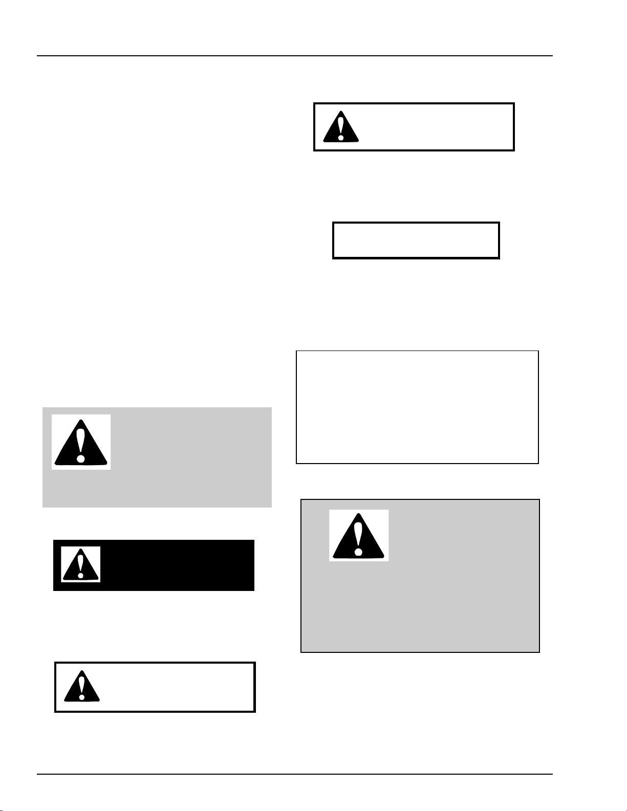
CAUTION
CAUTION indicates a potentially hazardous situation
which, if not avoided, ma y result in minor or moder ate
injury .
As owner and/or operator, it is your responsibility to know what requirements, hazards and
precautions exist and inform all personnel associated with, or in the area of the product. Safety
precautions may be required from the personnel.
This product is ideal for the conditioning of corn,
soy beans or other select grains. A void any alteration to the equipment, such alterations may produce a very dangerous situation, where serious injury or death may occur.
This is the safety alert symbol.
It is used to alert you to potential personal injury hazards.
Obey all safety messages that
follow this symbol to avoid possible injury or death.
DANGER
DANGER indicates an imminently hazardous situation
which, if not avoided, will result in death or serious injury
CAUTION
CAUTION used without the safety alert symbol indicates a potentially hazardous situation which, if not
avoided, ma y result in property damage.
If a decal is damaged or missing contact:
The GSI Group Inc.
1004 E. Illinois St.
Assumption, IL 62510
217-226-4421
A free replacement will be sent to you.
BE ALERT!
Danger!
Personnel operating or
working around electrical
equipment should read this
manual. This manual must be delivered with
equipment to its owner. Failure to read this
manual and its safety instructions is a misuse
of the equipment.
WARNING
WARNING indicates a potentially hazardous situation
which , if not avoided, could result in death or serious
injury .
4
The GSI Group Inc. recommends that you
contact your local power company and have a representative review your installation so your wiring will be compatible with their system and so
that you will have adequate power supplied to your
unit.
Page 5
Series 2000 Downwind Heater
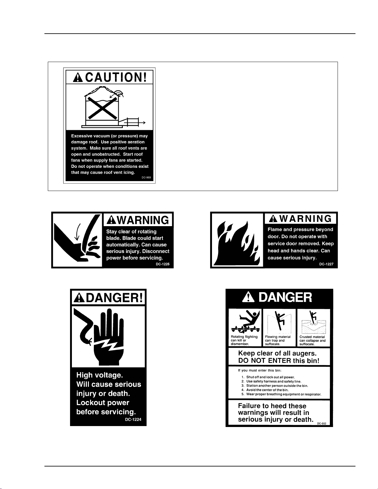
Roof Damage Warning And Disclaimer
SAFETY
GSI DOES NOT WARRANT ANY ROOF DAMAGE
CAUSED BY EXCESSIVE VACUUM OR INTERNAL PRESSURE FROM FANS OR OTHER AIR MOVING SYSTEMS.
ADEQUA TE VENTILATION AND/OR "MAKEUP AIR" DEVICES SHOULD BE PROVIDED FOR ALL POWERED AIR
HANDLING SYSTEMS. GSI DOES NOT RECOMMEND
THE USE OF DOWNW ARD FLOW SYSTEMS (SUCTION).
SEVERE ROOF DAMAGE CAN RESULT FROM ANY
BLOCKAGE OF AIR PASSAGES. RUNNING FANS DURING HIGH HUMIDITY/COLD WEATHER CONDITIONS
CAN CAUSE AIR EXHAUST OR INTAKE PORTS
5
Page 6

SPECIFICATIONS
Series 2000 Downwind Heater
Centrifugal Heater Specifications
Hi-Temp Hi-Temp Lo-Temp Model
10-15HP 20-40HP All un its
All Models BTU Rating 2225000 4500000 500000
Weight 145 145 135
Liquid Models Maximum Fuel flow (GPH) 24 49 N/A
Orifice siz e 0.2188 0.3125 N/A
Mod Valve Bypass Orifice Blue Aluminum Yellow
Minimum operating pressure 1 1 N/A
Maximum operating pressure 15 15 N/A
Minimum lin e si ze 3/8" 3/8" N/A
Va por Models Maximum Fuel flow (CFH) 931 1898 210
Ori f i ce si ze 0.2188 0.3125 0.109
Mod Valve Bypass Orifice Blue Aluminum Yellow
Minimum operating pressure 1 1 1
Maximum operating pressure 15 15 15
Minimum line size 3/8" 3/8" 1/2"
Natural Gas Maximum Fuel flow (CFH) 2496 4643 500
Models Or ifice size 0. 3438 0.4688 0.156
Mod Valve Bypass Orifice Aluminum Aluminum Green
Minimum operating pressure 0.5 0.5 1
Maximum operating pressure 7 7 7
Minimum line size 1. 1/4" 1.1/4" 1"
Heater Dimensional Specifications
Heater Size
Inside Height
Inside Width
Inside length
6
10-15
30.1/4"
19.1/2"
24"
20-30
33.1/4"
21.3/4"
24"
40
33.1/4"
23.11/16"
24"
Page 7
Series 2000 Downwind Heater
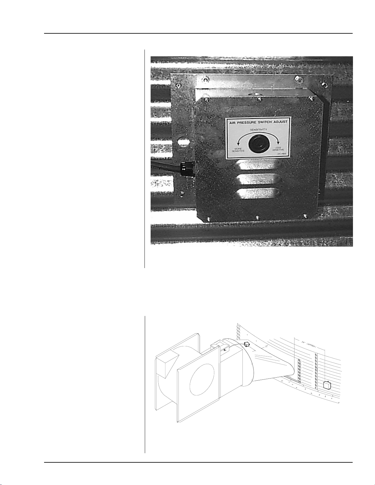
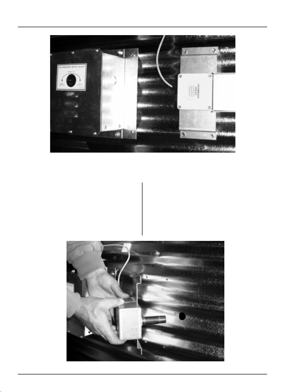
Air Pressure Switch and
Temperature Sensor Box
Installation
1. Using air switch box as a
guide, mark 2 holes on plenum side wall appproximately
24" to right of transition centered up and down in plenum.
2. Drill air switch filter hole 5/8"
diameter for snug fit. Drill temperature sensor hole 5/8" or
larger to accommodate mounting
nut.
3. Mount Box to Bin using (4)
self drilling screws
HEATER INSTALLATION
4. Caulk between housing and sidewall to seal.
1. Mark location on transition
one (1) foot up from the bottom (entrance collar) and centered in the transition.
2. Drill or knock out 7/8" diameter hole on marked location.
3. Install transition hi-limit using
supplied self drilling screws.
Air Switch Box Assembly
Transition Hi-limit Installation
Figure 1: The transition connecting the Series 2000 Heater to the bin with
the sensor in place.
7
Page 8
HEATER INSTALLATION
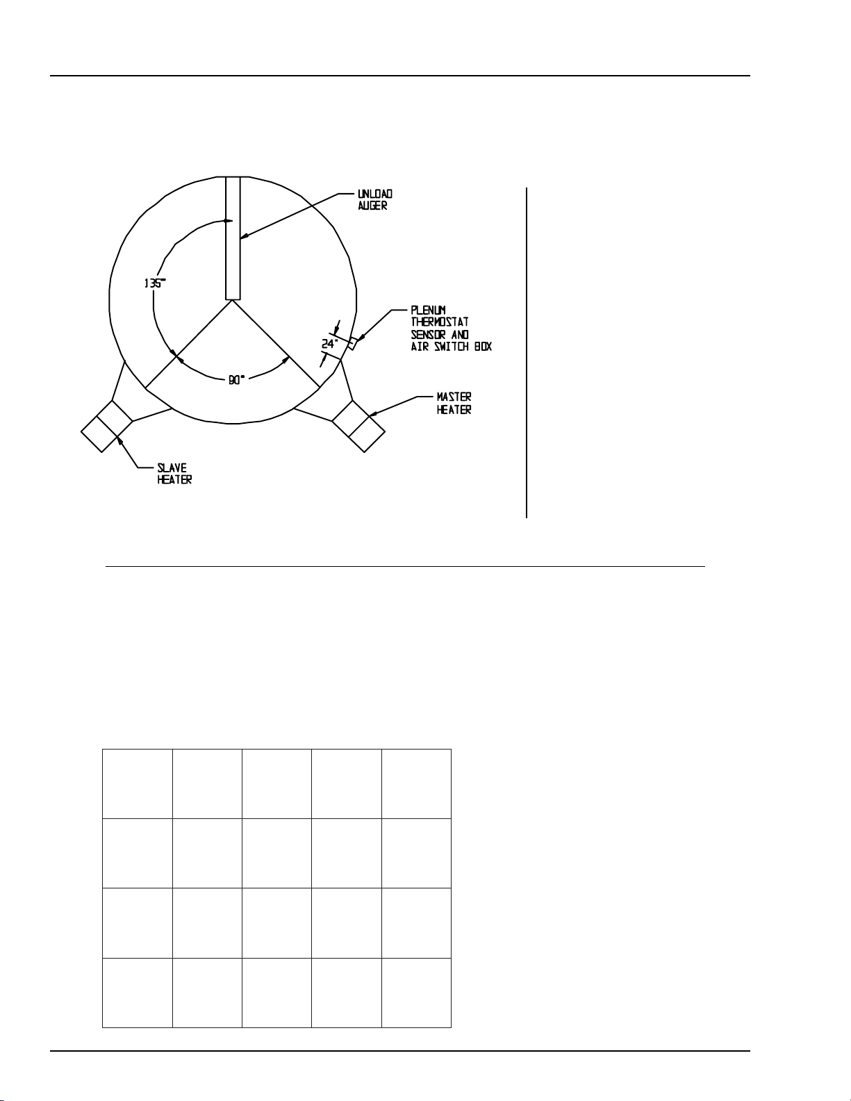
Bin Configuration
Series 2000 Downwind Heater
IMPORTANT! When
mounting (2) heaters on a
bin it is imperative that
they be situated as
illustrated in this drawing. Plenum thermostat
must be to the right of
master heater and master
heater must be to the
right of slave heater .
THIS TABLE IS NOT INTENDED AS A DRYING GUIDE.
IT SHOULD BE USED AS A REFERENCE FOR SETTING MAXIMUM PLENUM
TEMPERATURE FOR SAFE OPERATION.
Operating Temperature Table
PMET-OL
HCTAB
0
02-5
NROC
ECIR
SNAEB
&
TAEHW
EVOBA
TNEIBMA
PMET
0
01-5
EVOBA
TNEIBMA
PMET
0
02-5
EVOBA
TNEIBMA
PMET
-HGIH
PMET
YRDHCTAB
GNIRRITSON
0
021
0
001
0
011
-HGIH
PMET
HTIW
GNIRRITS
0
041
SUOUNITNOC
WOLF
)GNITALUCRICER(
0
061
IMPORTANT!
DO NOT EXCEED
PLENUM
TEMPERATURES
0
001
0
021
TON
DEDNEMMOCER
TON
DEDNEMMOCER
LISTED IN TABLE
8
Page 9
Series 2000 Downwind Heater
HEATER INSTALLATION
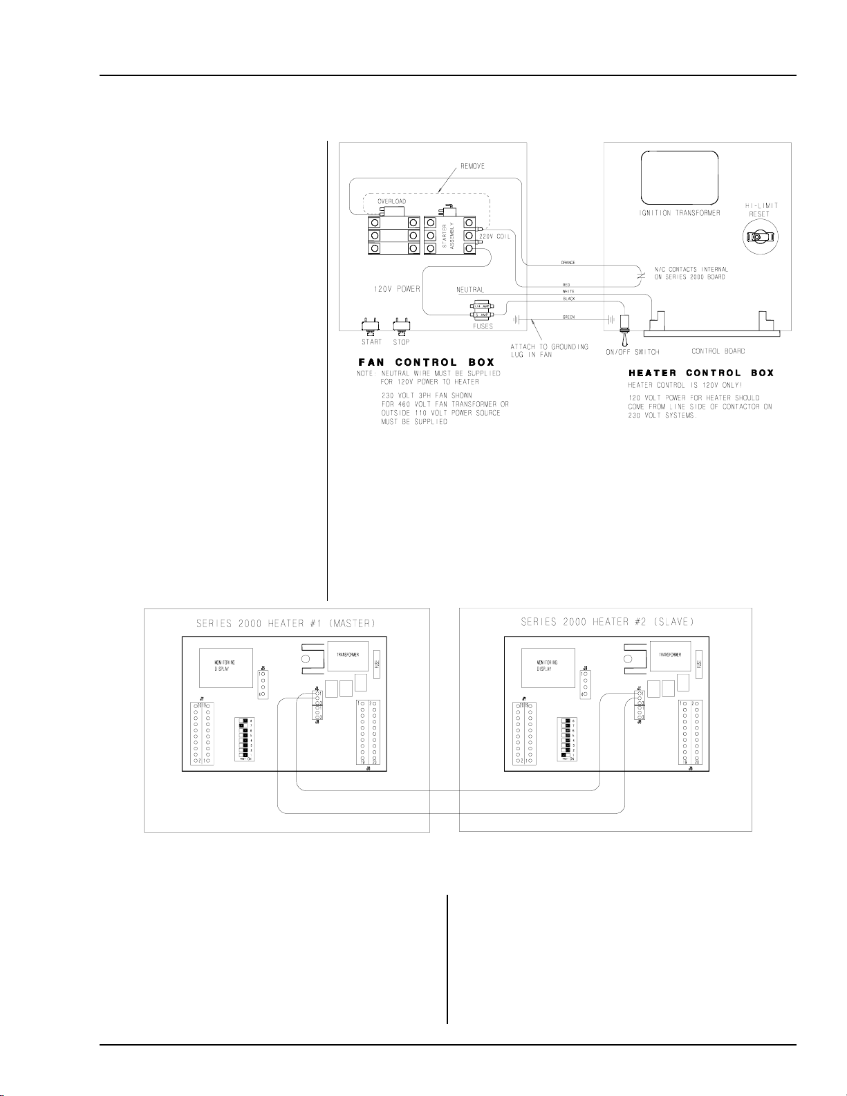
Heater Unit
1. Be sure fan unit is installed and
wired to meet local codes. Be
sure equipment is well grounded
(see page 10).
2. A separate neutral is required
for 120 volt heater circuit in 220
volt 1PH and 3PH fan units. For
460 volt fan units a separate 120
volt power supply or transformer
is required.
3. Run 5-wire black cord from
heater unit to fan unit and se-
cure to fan.
4. Orange and red wires should be
connected in series with coil in
fan. When contacts in heater be-
tween these wires open fan
Wiring
Figure 2: Wiring diagram for the fan and heater unit.
shuts down. Recommended wiring is shown in Figure 2.
5. Black and white wires should be connected to a fused 120V
power supply as shown. Green wire should be connected to
ground in fan. Heater should have power, even with fan off.
Figure 3: Secondary heater wiring diagram.
SECONDARY HEATER UNIT
1. Secondary heater unit runs as a slave of heater
unit #1 and requires no plenum temperature
sensor.
2. Run (2) 20 gauge (minimum) wires from sec-
ondary heater unit (slave) to heater unit #1
(master).
3.
Connect wires as shown in Figure 3.
4. Third heater unit may also be added to system.
If adding third unit, run connections to master
unit #1 and connect them in parallel with sec
ondary heater unit.
9
Page 10
HEATER INSTALLATION
Machine To Earth
Ground
It is very important that a machine
to earth ground rod be installed at
the fan. This is true even if there is
a ground at the pole 15 feet away.
This ground needs to be as close to
the fan as possible, but no more than
8 feet away. The ground rod should
be connected to the fan control panel
with at least a #6 solid bare copper
ground wire, or in accordance with
local requirements. The machine to
earth ground provides additional
safety if there is a short. It also provides the grounding necessary for
long life and operation of the solid
state circuit boards used on control
circuits and the electronic ignition
systems.
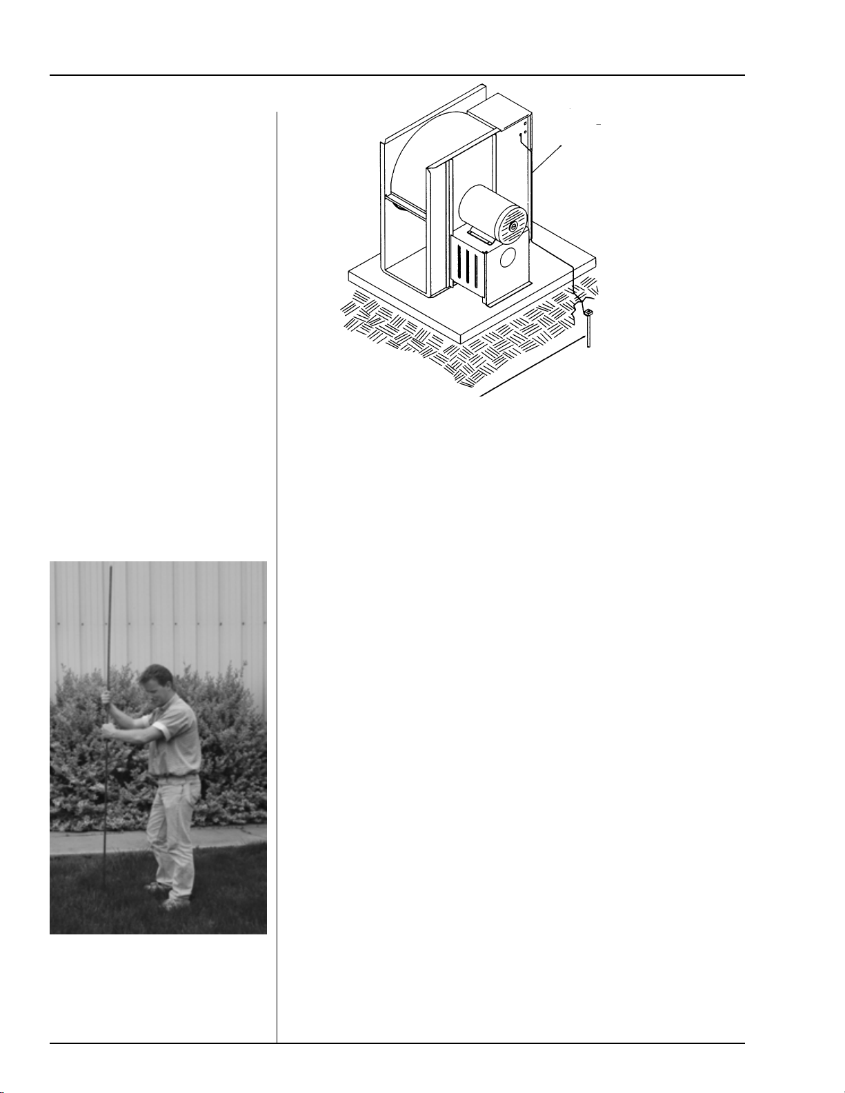
(Ground rods and wires are not supplied by Airstream). It is recommended that
the rod not be driven into dry ground. The following steps ensure proper ground
rod installation:
1. Dig a hole large enough to hold 1 to 2 gallons of water.
2. Fill hole with water.
Series 2000 Downwind Heater
Figure 4: Use a
#6 or approved
size bare copper
ground wire.
Install a 5/8"
diameter 8' long
copper-clad
ground rod, 2'
away from the
foundation and 1'
below the surface
of the ground or
in accordance
with local
requirements.
Proper Installation Of The Ground Rod
Dig a hole large enough to hold 1
or 2 gallons of water. Work the
ground rod into the earth until it is
completely in the ground.
3. Insert rod through water and jab it into the ground.
4. Continue jabbing the rod up and down, the water will work its way
down the hole, making it possible to work the rod completely
into the ground. This method of installing the rod gives a good
conductive bond with the surrounding soil.
5. Connect the bare copper ground wire to the rod with the proper
ground rod clamp.
6. Connect the bare ground wire to the fan control boxes with a
grounding lug. See figure 4.
7. Ground wire must not have any breaks or splices. Insulated
wire is not recommended for grounding.
Previously Installed Units
It is recommended that previously installed units be checked to see
that a machine to earth ground has been installed by an electrician.
10
Page 11
Series 2000 Downwind Heater
HEATER INSTALLATION
Standard electrical safety practices and codes should be used
when working with a heater.
Refer to the National Electric
Code Standard Handbook by
the National Fire Protection
Association. A qualified elec-
trician should make all wiring
installations.
ALWAYS DISCONNECT
AND LOCK OUT
BEFORE WORKING ON
OR AROUND HEATER
Fuel Connection
Liquid Propane Models
1. L.P. models are designed to run on liquid pro
pane with liquid draw from the propane tank.
A void using propane supply tanks that have been
used for vapor draw for long periods of time.
When using liquid draw systems any moisture
that may be present in tank or lines may freeze
when system is used in cold weather. To avoid
this situation, purge the system with methanol.
2. Run proper size line (see specification on page
7) to liquid pipetrain on heater. Have a qualified
gas service person inspect installation to be sure
that everything is installed according to local
codes and ordinances.
POWER
2. Run proper size line (see specifications on page
3. After installation is complete check all connec-
1. Natural gas models are designed to run directly
IMPORTANT! Do not use propane tanks that have previously been used for ammonia
unless they have been purged
according to procedures of the
National L.P. Association.
Fuel supply system must
comply with local codes for L.P .
gas installation.
external vaporizer.
7) to pipetrain on heater. Have a qualified gas
service person inspect installation to be sure that
everything is installed according to local codes
and ordinances.
tions for leaks. DO NOT USE FLAME FOR
LEAK TESTING.
Natural Gas Models
off of a supply tank or from a separate
external vaporizer.
3. After installation is complete check all connections for leaks with liquid detergent or comparable. Wear rubber gloves and eye protection.
Avoid contact with liquid propane. DO NOT
USE FLAME FOR LEAK TESTING.
Propane Vapor Models
1. Propane vapor models are designed to run directly off of a supply tank or from a separate
2. Run proper size line (see specification on page 7)
to pipetrain on heater. Have a qualified gas
service person inspect installation to be sure everything is installed according to local codes
and ordinances.
3. After installation is complete check all connections for leaks. DO NOT USE FLAME FOR
LEAK TESTING.
11
Page 12
HEATER INSTALLATION
Figure A
Series 2000 Downwind Heater
Installing Optional Humidity Sensor
1. Humidity sensor should be mounted 6-8"
right of the airswitch/temperature sensor
box. See Figure A.
2. Using sensor as a guide drill or knock-out
7/8" diameter hole in the center of the
plenum on the bin sidewall. If you are
using sensor to sense drying air humidity.
3. Insert pipe nipple from sensor housing
throughhole in side wall and use selfdrilling screws to mount to sidewall.
Figure B
4. Do not caulk sensor box openings on side
of box, they are for air escape.
12
Figure B
Page 13
Series 2000 Downwind Heater
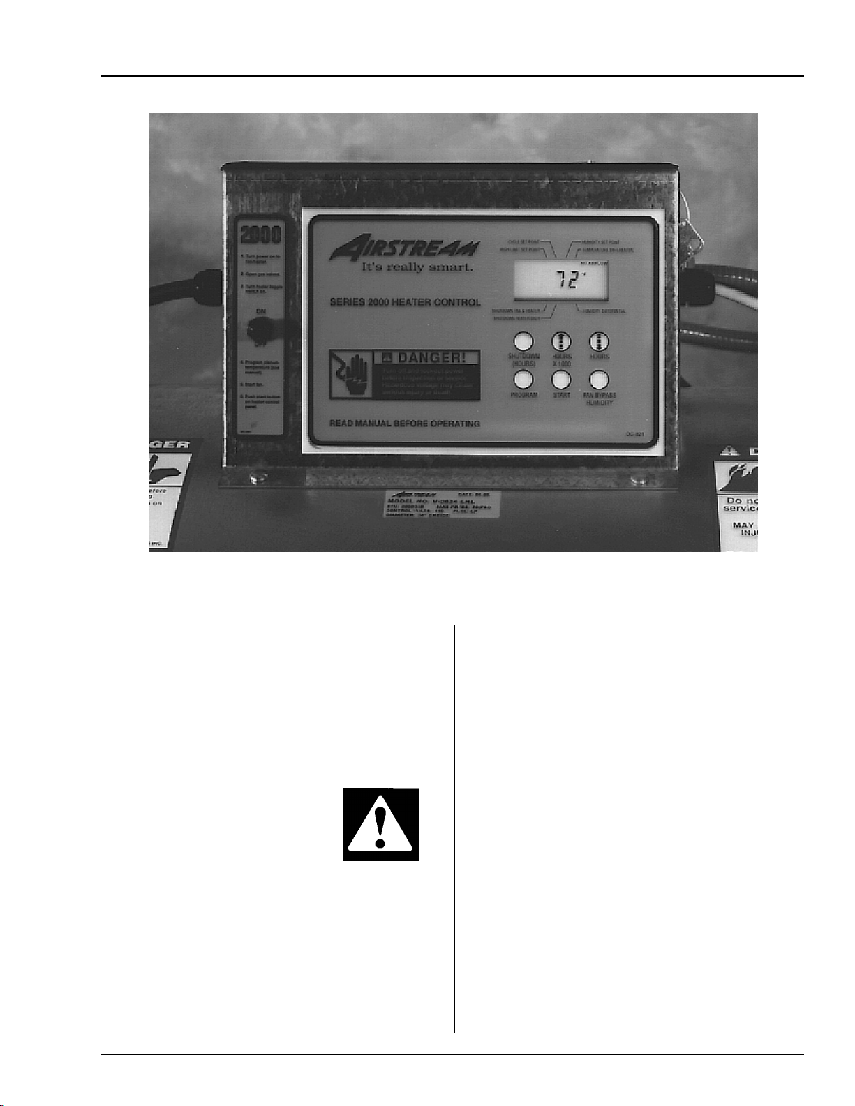
OPERATING PROCEDURE
The control panel display showing initial start up.
Standard electrical safety practices and codes should
be used when working with a heater. Refer to the
National Electric Code Standard Handbook by
the National Fire Protection Association. A quali-
fied electrician should make all wiring installations.
ALWAYS DISCONNECT
AND LOCK OUT POWER
BEFORE WORKING ON
OR AROUND HEATER
Power Up
All safety and high limit switches are checked upon
power up. If a safety or limit is open, the control displays it. The control cannot operate with a safety switch
error, and the fan cannot turn on with an error condi-
tion. There is no way to bypass an error condition. It
must be fixed. (See errors on page 21)
The air switch is also checked on power up.
The air switch must indicate no airflow. This is
necessary to check the function of the air switch.
However, if the operator for gets and turns the fan
on before the controller has been powered up,
The controller locks up with the main display alternating between a "FAN" and "ON" message. This
may be bypassed by depressing and holding the
"FAN BYPASS" switch (lower right switch). Normal operating procedure should be to power up the
controller with the fan off.
If multiple heaters are tied together, and the
master detects that the slave fan is on (the air
switch stuck?), the master will lock up displaying "SLA ERROR". This condition may be bypassed with the "FAN BYPASS" switch.
13
Page 14
OPERATING PROCEDURE
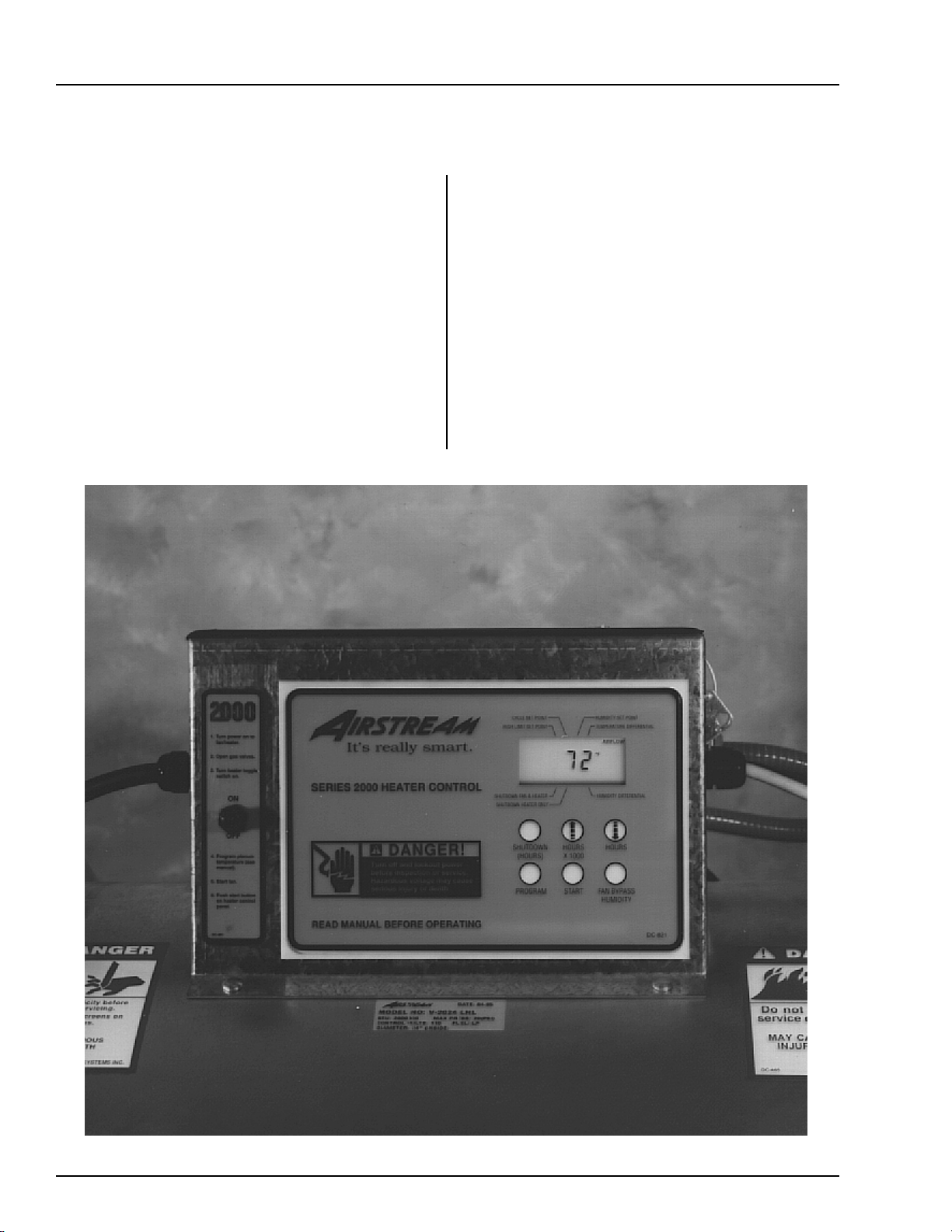
Normal Operating Displays With Heater Not Running
Series 2000 Downwind Heater
The main display shows the plenum temperature. If
the dryer has not been running, the display should
show outside temperature. The control is preset at
the factory to display temperature in centigrade or
fahrenheit.
"AIRFLOW" or "NO AIRFLOW" is displayed
if air is flowing or not flowing. "RX TX" (receive,
transmit) is displayed if multiple heaters are connected.
All safeties or high limits are continuously
checked during the off mode. A limit switch open,
or any other error condition will cause the display
to show the limit or error condition.
When drying is not occurring, and the limit
or error condition is corrected, the display returns
to its normal output. This is not the case with an
error or limit condition during the drying operation. This causes the display to lock up in the error display mode. This is to keep the display
locked up with the condition illuminated. ( see
section on "Running the Dryer" for mode explanation on page 17).
14
The heater display with fan on (airflow).
Page 15

Series 2000 Downwind Heater
Starting The Dryer
After heater power is turned on, the fan must be
turned on. Attempting to start the dryer without the
air switch indicating there is airflow will cause an airflow alarm to go off when the start switch is depressed.
The airflow alarm is simply the entire display going
blank, and the "NO AIRFLOW" message flashing for
a few seconds. The display must show "AIRFLOW"
before the dryer can be started.
T o start the dryer, just push the "ST AR T" switch.
The first message to come up will be the "PURGE"
message--the drying process begins with a 10 second purge.
When multiple heaters are connected together,
drying may be started from any heater control.
OPERATING PROCEDURE
Programming the temperature differential.
7. Press the "PROGRAM TEMPERATURE" but
ton to continue to set the "TEMPERATURE
DIFFERENTIAL".
8. Use the increase or decrease buttons to set the
"TEMPERATURE DIFFERENTIAL" to 10°*.
Setting Gas Pressure
1. At heater turn toggle switch to "ON" position.
2. Press the "PROGRAM TEMPERATURE" button.
3. Use the increase or decrease button to set the
"PLENUM HIGH LIMIT SET POINT" to desired setting (100°-160°*).
4. Press the "PROGRAM TEMPERATURE" button to continue to set the "CYCLE SETPOINT".
(hi-lo units only)
5. Use the increase or decrease buttons to set the
"CYCLE SET POINT" to desired setting (90°150°*) (hi-lo units only).
9. Press "progam temperature" button to continue
to set "relative humidity differential". Use arrow keys to adjust to 5%. ( Hudidity sensor units
only).
10. Open all manual gas shut off valves, on and to
the heater unit.
11 Start the fan unit.
12. Make sure that the blade is spinning in the right
direction. If not place the toggle switch in the
"OFF" position and correct the problem.
13. After the fan reaches full speed the display should
read "AIRFLOW" in the upper right hand corner.
If not adjust air switch. (See page 19)
14. Press the start button on the heater control.
6. Press "programs temperature" button to continue
to set the desired "relative humidity" setting,
lower setting will run heater longer. (humidity
sensor units only) Use arrow keys to set.
15. After 10 seconds the burner should ignite. If not,
turn "OFF" the toggle switch and then back "ON".
Repeat 12-15.
*Temperatures are fahrenheit.
15
Page 16

OPERATING PROCEDURE
Series 2000 Downwind Heater
16. When the burner ignites the display should read
"HI-FLAME " at the left of the display . Loosen
the nut on the main regulator and turn screw in, to
increase pressure and out to decrease pressure.
The pressure gauges should be set at 10-15 lbs.
for LP units, or 4-6 lbs.. for natural gas units. (use
the charts on the following pages to set pressure)
17. Press the "PROGRAM TEMPERA TURE" but-
ton to change the high limit set point. Press it
again to change the "CYCLE SET POINT". (hilo units only)
18. Decrease the "CYCLE SET POINT TEM
PERATURE" until the heater cycles to low
flame. (hi-lo units only)
19. Open or close the low cycle ball valve until
the gas pressure is 3-5 lbs. for LP, or 1-2 lbs.
for natural gas. (hi-lo units only)
20. Increase the cycle set point toreturn to high
flame. (hi-lo units only)
21. Watch heater run several minutes to make
sure it cycles between hi and lo flame or on
andoff properly.
22. Hi-flame pressure should be adjusted so plenum reaches cycling temperature easily.
23. Adjust pressure on on/off units so that unit is
on approximately 75% of the time.
16
Page 17

Series 2000 Downwind Heater
g
(°F)
)
g
g
(°F)
)
BTUs Per Gauge Pressure (psi) PROPANE MODELS (Approximate
Hi
2 4 6 8 10 12 14 15
ALL
MODELS
816,013 1,148,640 1,409,477 1,632,026 1,825,859 1,995,762 2,153,700 2,227,883
Gau
e Pressure (psi) Required to Maintain Temperature (Approximate)
(10-15 hp High Temperature Propane Units Only)
OPERATING PROCEDURE
10-15 hp Units
h Temperature 10-15hp 7/32" (0.219") Orifice
OPERATING PRESSURE (psi)
Fan Static
Model Pressure 60 80 100 120 140 160 180
2"24681013
10 hp4"135681114
6"11356810
2" 3 6 9 12 15
15 hp 4" 3 5 7 10 13
6"235691114
Heat Rise
10-15 hp Units
BTUs Per Gauge Pressure (psi) NATURAL GAS MODELS (Approximate
High Temperature 10-15hp 11/32" (0.344") Orifice
OPERATING PRESSURE (psi)
1234567
ALL
MODELS
859,104 1,218,432 1,489,296 1,718,208 1,921,584 2,107,632 2,276,352
e Pressure (psi) Required to Maintain Temperature (Approximate)
Gau
(10-15 hp High Temperature Natural Gas Units Only)
Heat Rise
17
Fan Static
Model Pressure 60 80 100 120 140 160 180
2" 1 1.75 2.5 3.5 4.75 6
10 hp 4" 0.75 1.25 2 2.75 3.75 4.75 6
6" 0.5 1 1.5 2 2.75 3.5 4.25
2" 1.5 2.5 3.75 5.5
15 hp 4" 1.25 2 3 4.25 5.75
6" 0.75 1.25 2 2.75 3.75 5 6
Page 18

OPERATING PROCEDURE
g
(°F)
)
g
BTUs Per Gauge Pressure (psi) PROPANE MODELS (Approximate
Hi
h Temperature 20-40hp 5/16" (0.313") Orifice
OPERATING PRESSURE (psi)
2 4 6 8 10 12 14 15
ALL
MODELS
1,663,135 2,345,140 2,878,779 3,328,663 3,721,115 4,068,100 4,393,548 4,541,914
e Pressure (psi) Required to Maintain Temperature (Approximate)
Gau
(20-40 hp High Temperature Propane Units Only)
Series 2000 Downwind Heater
20-40 hp Units
Fan Static
Model Pressure 60 80 100 120 140 160 180
2"22457810
20 hp 4" 1 2 3 4 5 7 8
6"1234567
2" 2 3 5 7 9 12 15
25 hp 4" 2 3 4 6 8 10 13
6"22456810
2"24681115
30 hp 4" 2 4 5 7 10 13
6" 2 3 4 6 8 10 13
2" 3 6 8 12
40 hp 4" 3 5 7 11 14
6"347912
Heat Rise
18
Page 19

Series 2000 Downwind Heater
g
(°F)
)
BTUs Per Gauge Pressure (psi) NATURAL GAS MODELS (Approximate
High Temperature 20-40hp 15/32" (0.469") Orifice
OPERATING PRESSURE (psi)
1234567
ALL
MODELS
1,597,824 2,266,320 2,770,656 3,195,648 3,573,216 3,919,776 4,234,416
Gau
e Pressure (psi) Required to Maintain Temperature (Approximate)
(20-40 hp High Temperature Natural Gas Units Only)
OPERATING PROCEDURE
20-40 hp Units
Fan Static
Model Pressure 60 80 100 120 140 160 180
2" 0.75 1.25 1.75 2.5 3.25 4.25 5.5
20 hp 4" 0.5 1 1.5 2 2.75 3.5 4.5
6" 0.5 0.75 1.25 1.75 2.25 3 3.75
2" 1 1.75 2.25 3.5 4.75 6.25
25 hp 4" 0.75 1.5 2.25 3.25 4 5.25 6.25
6" 0.5 1.25 1.75 2.5 3.25 4.25 5.5
2" 1.25 2 3 4.5 6
30 hp 4" 1 1.75 2.75 3.75 5 7
6" 0.75 1.5 2.25 3 4 5.25 7
2" 1.75 3 4.5 6.25
40 hp 4" 1.5 2.5 4 5.5
6" 1.25 2.25 3.5 4.75 6.75
Heat Rise
19
Page 20

OPERATING PROCEDURE
)
(App
)
(
g
)
(App
)
Lo-Temp Units
BTUs Per Gauge Pressure (psi
PROPANE MODELS
Series 2000 Downwind Heater
roximate
ALL
MODELS
Low Temperature All hp 7/64"
OPERATING PRESSURE (psi)
2 4 6 8 10 12 14 15
203,405 287,160 351,771 409,203 457,063 497,744 538,425 555,176
0.109") Orifice
Lo-Temp Units
BTUs Per Gau
NATURAL GAS MODELS
e Pressure (psi
roximate
20
ALL
MODELS
Low Temperature All hp 5/32" (0.156") Orifice
OPERATING PRESSURE (psi)
1234567
177,840 251,712 308,256 355,680 397,632 435,936 470,592
Page 21

Series 2000 Downwind Heater
Adjusting the Air Pressure Switch
AIR PRESSURE SWITCH
1. Air pressure switch must be adjusted so
that it will activate with lowest level of
grain that will be dryed in bin.
2. Put grain in bin to level desired (low).
3. With heater on and fan off display on
heater should read "no airflow".
4. Start fan. Heater display should now read
"airflow".
5. If display does not read "airflow" remove
cap from adjustment port and slowly turn
screw counter clockwise until display does
read "Airflow". Figure C
6. Shut fan off display should read "no air
flow" when fan gets to half speed. If not
repeat step 5.
Figure C
21
Page 22

OPERATING PROCEDURE
Series 2000 Downwind Heater
Adjusting The Vaporizor
1. V aporizer should be adjusted so
the vapor pipetrain runs warm
to the touch (100°-120°F).
2. Loosen 5/16" bolt on adjust-
ment bracket.
3. Swivel vaporizer away from
flame if running too hot, closer
to flame if too cold.
4. Move vaporizer only 1" at a time
and allow a few minutes for
temperature to equalize.
Adjusting the vaporizer coil on a liquid propane model. The top photo
shows the setting in, and the bottom photo shows the coil out.
5. Tighten 5/16" bolt and watch
heater run for several minutes
to verify adjustment.
Running The Dryer
The display will indicate "FLAME"
when flame is sensed. If no flame
is sensed, the "FLAME" message
will be off. The display indicates
what part of the cycle it is in. If the
unit is a hi-lo dryer, the display will
indicate whether it is in the "HIFLAME" or "LO-FLAME" part of
the cycle. (See "programming set
points" page 21 for setting the hi-lo
flame temperature). If the temperature is above the high temperature setting, the flame will be off, the
"FLAME" message will be out and the
display will be flashing "OFFCYCLE".
If the flame is shut off because
of the humidity sensor (humidistat),
the display flashes "OFF-CYCLE
HUMIDISTAT".
22
Page 23

Series 2000 Downwind Heater
OPERATING PROCEDURE
The limits are continuously
checked during the drying operation.
A limit switch open or any other error condition will cause the dryer to
shutdown, and the fan will be shutdown. If a limit opens, or an er-
ror condition occurs during drying, the control will lockup in the
error display mode. Power must
be shut off and back on to the control to clear the error condition-even if the error or limit that
caused the shutdown has been
corrected. This is to keep the dis-
play locked up with the condition
that caused the error, allowing the
operator time to determine what
caused the shutdown.
Multiple heaters may be done at any heater control console. The information programmed is automatically transmitted to all other heaters when the
programming is complete.
Hi Limit Set Point--The upper left cursor is flashing indicating the
mode. If the plenum temperature increases above this point, the flame is
shut off--"OFF-CYCLE" is displayed on screen.
Cycle Set Point--The upper 2nd from left cursor is flashing indicating
the mode. If the dryer is not a hi-lo dryer, this function is skipped. If
the plenum temperature increases above this point, the flame reduces to
"LO-FLAME".
Humidity Set Point--The upper 2nd from right cursor is flashing indi-
cating the mode. If the humidity is above this point the dryer operates
normally--flame on and off at the high limit and cycle set points. If the
humidity is below this point the dryer goes into the "OFF-CYCLE" mode.
Temperature Differential--The upper right cursor is flashing indicating
the mode. If the flame shuts off because the temperature is greater than the
high limit set point, the temperature must fall below the (Set Point minus
T emperature Differential) for the flame to come back on.
Programming Set Points
Depressing the "PROGRAM"
switch (lower left) causes the display to enter the program mode.
Each item below is programmed by
using the up and down arrow
switches. Holding down these up
and down arrow switches for about
2 seconds will cause the numbers to
increase/decrease rapidly until the
switch is released. When finished
programming an item, depressing
the "PROGRAM" switch again will
cause the new setting to be entered
into memory, and the display will
advance to the next function to be
programmed.
Programming may be done at
anytime (unless an error condition
exists) even while the dryer is in
operation.
Programming a system with
Programming the high-limit set point.
23
Page 24

OPERATING PROCEDURE
Series 2000 Downwind Heater
On hi-lo units when the unit reaches cycle set point, the flame will
switch to lo-flame and unit will not cycle back to hi-flame until (Set
Point minus Temperature Differential) is reached.
T emperature differential would normally be set for 10-15 degrees F
for high temp units, and 2-5 degrees F for lo-temp units.
Humidity Differential--The upper right cursor is flashing indicating the mode. If the flame shuts off because the humidity set point, the
humidity must rise above the ( Set Point plus Humidity Differential) for
the flame to come back on. (Normally set to 5%)
Programming Hours To Shutdown
To change the hours to shutdown, depress and hold the "SHUTDOWN
HOURS" switch. While holding in on the switch, depress the up and
down arrow switches to alter the
hours. Setting range is 0 to 200
hours.
Drying Grain In The
Hours To Shutdown
Mode
While drying grain, depress and
hold the "SHUTDOWN HOURS"
switch. While holding in on that
switch, depress the "START"
switch. After depressing the start
switch one time, the heater is in the
shutdown mode. Then, the fan and
heater shutdown when the time expires. This is indicated by the lower
left cursor flashing.
Depressing the start switch
again (while holding in on the
"SHUTDOWN HOURS" switch)
will cause only the heater to shut off.
This leaves the fan on when the time
expires. This is indicated by the 2nd
from lower left cursor flashing. Depressing the start switch one more
time returns the heater into the continuous--non-shutdown mode.
24
Setting the cycle set point.
Run Hours Display
Run hours are recorded when the
controller detects that the fan is on
(airflow). The hours may be viewed
by depressing the "HOURS" to get
hours and "HOURS X 1000" to get
the number of 1000 hours accumulated.
Multiple Heater Notes
When multiple heaters are connected together, the temperature and
humidity sensors must be connected
to the master.
Page 25

Series 2000 Downwind Heater
Modulating Valve Operation
OPERATING PROCEDURE
1. The modulating valve regulates gas flow through
the heater based on sensing unit in the plenum,
and maintains a constant drying air temperature.
2. The sensing bulb of the modulating valve should
be mounted through the bin wall with the side
reading "top" up. The bulb reacts to temperature. It changes the amount of gas (increase or
decrease), burning warmer or cooler depending
on the position of the valve SET POINT. If the
bulb is cooler than it was at the SET POINT , the
bulb senses the cooler temperature and opens
the valve further so more heat is applied to the
drying air. If the bulb is warmer than it was at
the SET POINT , the valve closes further and reduces the temperature until the air is at the valve
SET POINT .
3. It is important that the pressure regulator be set
high enough to allow the modulating valve to
deliver enough gas to maintain the plenum temperature necessary . The regulator is normally
factory set at 15 psi (propane units). To set the
regulator, run the heater and turn the modulat
ing valve T-handle in. This gets full line pressure to the burner. Then adjust regulator to read
15 psi (depending on the plenum temperature
needed).
4. Turn the fan and heater on. T o set the modulating valve, turn the T-handle out (counterclockwise)
until loose and wait a few minutes for the plenum temperature to equalize. When the temperature under the bin has equalized, gradually turn
T-handle in (clockwise) about 1/2 turn at a time.
W ait until temperature under bin has equalized as
before. If temperature under bin is less than the
desired temperature, continue turning T-handle
in, increasing gas flow and waiting for plenum
temperature to equalize until the desired temperature is the stable temperature of the ple
num. If temperature under bin is the same 10
minutes after you last made any adjustments
to the T-handle you can be certain that the
temperature under the bin is the SET POINT
of the valve. 1 turn of the T-handle equals
approximately 7 degrees F of temperature.
5. The valve will now keep the plenum temperature at the set point regardless of ambient
conditions as long as humidistat or thermostat
do not shut down the heater. A bypass orifice
is used to maintain a small flame when outside temperature is near or above the set point
of the valve. The bypass insures steady application of heat at minimum gas flow operation.
Bypass orifice will only operate correctly if
pressure regulator is set correctly .
6. To observe how the modulating valve increases
the efficiency of bin drying, check the gas pressure of the unit in the morning and compare to
the pressure read mid-afternoon. If the ambient (outside) temperature is significantly
greater later in the day (as normal), the gas pres
sure will be less. Since less heat is required to
maintain the same temperature in the plenum,
the modulating valve will have reduced the
amount of gas used by the heater.
25
Page 26

FACTORY CONFIGURATION
Series 2000 Downwind Heater
Configuration Dip
Switches (Normally Done
At GSI)
These switches are used to configure the heater control for various
types of heaters.
Stand alone heater
with no slaves, all
dip switches in the
off state.
Multiple heaters connected together through the serial link.
Master with one
slave-dip switch 7
on/all others off.
Master with two
slaves-dip switch 8
on/all others off.
Slave #1-dip switch
one and three on/all
others off.
Slave #2-dip switch
two and three on/all
others off.
Master with 3
slaves-dip switch 7
& 8 on/all others
off.
Slave #3-dip switch
one, two and three
on/all others off.
26
The backside of the control board, showing the dip switch placement.
Page 27

Series 2000 Downwind Heater
Limit Switches
ERROR CONDITIONS
The following limit switch errors light up individually on the heaters
LCD screen: PLENUM, HOUSING, VAPOR, TEMP HI LIMIT.
Note: When a shutdown does occur due to an error condition, the amount
of time elapsed since the shutdown can be viewed by pressing the down
arrow switch (up to 218 Hours).
"SLA" on the main display
and the "RX" "TX" symbols will be
flashing.
If a limit switch error or one of
the error numbers 1 through 8
occurs, that error is displayed on
Multiple Heater Error Conditions
If two or more heaters are connected together through the serial link, and the
master cannot communicate with a slave controller, the master will display
the slave where the error originates. The master displays
"SLA ERROR".
Misc Error Numbers
1 2 3 4 5 6
Temperature
probe 1 open.
7
Temperature
probe 1 short.
8 9 10 11 12
Temperature
probe 2 open.
Temperature
probe 2 short.
Airflow open.
Airflow short.
Illegal flame
sense.
Error 7 is
most likely
caused by stuck
open solenoid.
Error 7 will not
shutdown fan
until loss of
flame is detected
by control.
13
+11 volt DC
shorted to
ground.
The heater
control display
showing error
#7.
Flame probe
short error.
000
This indicates
that one of the
other on screen
errors (vapor,
plenum or
housing temp hi-
limit or flame out
or no airflow has
occurred).
Slave #1 incon-
sistent with mas-
ter with either
the drying grain
flag or the LP
main solenoid or
cycle solenoid.
Most likely
the slave got re-
set powering up
with the sole-
noids off.
(Errors 9 through 11 are displayed only if multiple heaters
are tied together through serial link).
Note: Temperature sensor connection-the temperature
sensor (bolt) must always be connected to the master.
Slave #2
inconsistent.
Same as
error 9 for slave
#1.
Slave #3
inconsistent.
Same as
error 9 for slave
#1.
Wrong voltage.
Dip switch
#5 is the voltage
selector switch.
If dip switch #5
in "ON" that se-
lects 240 VAC.
If the unit has
only 120 VAC
applied, error 12
will show up. If
dip switch #5 is
"OFF" that se-
lects 120 VAC. If
the unit has 240
VAC applied er-
ror 12 will show
up.
This is im-
portant because
if the fan heater
is set up at GSI
for 120 VAC and
the customer
connects to 240
VAC the heater
control will work,
but if allowed to
operate the so-
lenoids will have
240 VAC applied
to them which
will damage so-
lenoids.
27
Page 28

HEATER SERVICE
Series 2000 Downwind Heater
All Airstream heaters are constructed of durable
weather-resistant materials, so a minimum
amount of service should be required; however
before the unit is started for the first time each
season there are a few items that need to be
checked out. All damaged parts should be repaired
or replaced.
1. Disconnect and lock out power to fan and heater.
Open control box lid and inspect all components for moisture, vibration or rodent damage.
Inspect and tighten all loose terminal connections. Replace any damaged wiring.
2. Remove burner orifice tube and inspect for dirt
or foreign material. Clean out if necessary.
3. Inspect burner for wear or foreign material in
any of the ports. Clean or replace parts if necessary.
4. Inspect the spark plug and flame probe for cor
rosion and damage. Clean or replace if necessary.
28
The Series 2000 control box.
Page 29

Series 2000 Downwind Heater
WIRING DIAGRAM
29
Page 30

HEATER PARTS
Series 2000 Downwind Heater
10-15 Dw High Temp Heater Parts
1 HF-7076 10-15 HP Housing Assembly
2 HF-7288 Access Side Cover
3 HF-7380 Plastic View Window
4 HF-7379 Access Panel Cover Plate
5 HF-7287 Access Panel Holders
6 HF-7063 10-15 Diverter Plate
7 CD-0238 Ignitor (2 Required)
8 HF-7201 Ignitor Clamp Half (2 Required)
9 HF-7204 Ignitor Bracket
10 HF-7101 10-15 Diverter Angle
11 CD-0187 Flame Sensor Bracket (Deluxe, Sr 2000)
12 *THH-4179 Flame Sensor (Deluxe, Sr 2000)
13 HF-7290 10-15 Burner Brace
14 HH-7035 1 1/4" Coupling
15 HF-7083 1/4" Orifice (Propane)
15 HF-7034 3/8" Orifice (Natural Gas)
16 HF-7027 Orifice Tube Weldment
17 THH-4071 1/2" Elbow
18 HH-3854 1/2" x 6" Nipple
19 HH-3670 1/2" x 2.1/2" Nipple
20 S-7259 5/16" U-Bolt
21 HF-7079 Diverter Angle Cover
22 HF-7020 Vaporizer Support Weldment
23 HF-7297 Burner Support Plate
24 HF-7032 Vapor Cover Plate
25 HF-7023 HI-Fire Burner Assembly
NS HF-7261 10-40HP Spark Plug Wire
NS HF-7263 10-40HP Flame Probe Wire
30
Page 31

Series 2000 Downwind Heater
10-15 Dw Low Temp Heater Parts
HEATER PARTS
1 HF-7076 10-15 HP Housing Assembly
2 HF-7288 Access Side Cover
3 HF-7380 Plastic View Window
4 HF-7379 Access Panel Cover Plate
5 HF-7287 Access Panel Holders
6 HF-7063 10-15 Diverter Plate
7 CD-0238 Ignitor (2 Required)
8 HF-7201 Ignitor Clamp Half (2 Required)
9 HF-7204 Ignitor Bracket
10 HF-7101 10-15 Diverter Angle
11 CD-0187 Flame Sensor Bracket (Deluxe, Sr 2000)
12 *THH-4179 Flame Sensor (Deluxe, Sr 2000)
13 HF-7290 10-15 Burner Brace
14 HF-7072 LO-Fire Diverter Spacer
15 HF-7071 LO-Fire Diverter
16 HF-7070 LO-Fire Burner Assembly
17 HF-7035 7/64" Orifice (Propane)
17 HF-7036 5/32" Orifice (Natural Gas)
18 HF-7069 LO-fire Orifice Weldment
19 THH-4071 1/2" Elbow
20 HH-3854 1/2" x 6" Nipple
21 HH-3670 1/2" x 2.1/2" Nipple
22 S-7259 5/16" U-Bolt
23 HF-7079 Diverter Angle Cover
24 HF-7297 Burner Support Plate
25 HF-7032 Vapor Cover Plate
NS HF-7261 10-40HP Spark Plug Wire
NS HF-7263 10-40HP Flame Probe Wire
31
Page 32

HEATER PARTS
Series 2000 Downwind Heater
20-30 Dw High Temp Heater Parts
1 HF-7077 20-30 HP Housing Assembly
2 HF-7288 Access Side Cover
3 HF-7380 Plastic View Window
4 HF-7379 Access Panel Cover Plate
5 HF-7287 Access Panel Holders
6 HF-7064 20-30 Diverter Plate
7 CD-0238 Ignitor (2 Required)
8 HF-7201 Ignitor Clamp Half (2 Required)
9 HF-7204 Ignitor Bracket
10 HF-7102 20-30 Diverter Angle
11 CD-0187 Flame Sensor Bracket (Deluxe, Sr 2000)
12 *THH-4179 Flame Sensor (Deluxe, Sr 2000)
13 HF-7300 20-30 Burner Brace
14 HH-7035 1 1/4" Coupling
15 HF-7083 1/4" Orifice (Propane)
15 HF-7034 3/8" Orifice (Natural Gas)
16 HF-7027 Orifice Tube Weldment
17 THH-4071 1/2" Elbow
18 HH-3854 1/2" x 6" Nipple
19 HH-3670 1/2" x 2.1/2" Nipple
20 S-7259 5/16" U-Bolt
21 HF-7079 Diverter Angle Cover
22 HF-7020 Vaporizer Support Weldment
23 HF-7297 Burner Support Plate
24 HF-7032 Vapor Cover Plate
25 HF-7023 HI-Fire Burner Assembly
NS HF-7261 10-40HP Spark Plug Wire
NS HF-7263 10-40HP Flame Probe Wire
32
Page 33

Series 2000 Downwind Heater
20-30 Dw Low Temp Heater Parts
HEATER PARTS
1 HF-7077 20-30 HP Housing Assembly
2 HF-7288 Access Side Cover
3 HH-2020 Plastic View Window
4 HF-6914 Access Cover Plate
5 HF-7287 Access Panel Holders
6 HF-7064 20-30 Diverter Plate
7 CD-0238 Ignitor (2 Required)
8 HF-7201 Ignitor Clamp Half (2 Required)
9 HF-7204 Ignitor Bracket
10 HF-7102 20-30 Diverter Angle
11 CD-0187 Flame Sensor Bracket (Deluxe, Sr 2000)
12 *THH-4179 Flame Sensor (Deluxe, Sr 2000)
13 HF-7300 20-30 Burner Brace
14 HF-7072 LO-Fire Diverter Spacer
15 HF-7071 LO-Fire Diverter
16 HF-7070 LO-Fire Burner Assembly
17 HF-7035 7/64" Orifice (Propane)
17 HF-7036 5/32" Orifice (Natural Gas)
18 HF-7069 LO-fire Orifice Weldment
19 THH-4071 1/2" Elbow
20 HH-3854 1/2" x 6" Nipple
21 HH-3670 1/2" x 2.1/2" Nipple
22 S-7259 5/16" U-Bolt
23 HF-7079 Diverter Angle Cover
24 HF-7297 Burner Support Plate
25 HF-7032 Vapor Cover Plate
NS HF-7261 10-40HP Spark Plug Wire
NS HF-7263 10-40HP Flame Probe Wire
33
Page 34

HEATER PARTS
Series 2000 Downwind Heater
40hp Dw High Temp Heater Parts
1 HF-7472 40 HP Housing Assembly
2 HF-7288 Access Side Cover
3 HF-7380 Plastic View Window
4 HF-7379 Access Panel Cover Plate
5 HF-7287 Access Panel Holders
6 HF-7140 40 HP Diverter Plate
7 CD-0238 Ignitor (2 Required)
8 HF-7201 Ignitor Clamp Half (2 Required)
9 HF-7204 Ignitor Bracket
10 HF-7102 20-40 Diverter Angle
11 CD-0187 Flame Sensor Bracket (Deluxe, Sr 2000)
12 *THH-4179 Flame Sensor (Deluxe, Sr 2000)
13 HF-7304 40 Burner Brace
14 HH-7035 1 1/4" Coupling
15 HF-7083 1/4" Orifice (Propane)
15 HF-7034 3/8" Orifice (Natural Gas)
16 HF-7027 Orifice Tube Weldment
17 THH-4071 1/2" Elbow
18 HH-3854 1/2" x 6" Nipple
19 HH-3670 1/2" x 2.1/2" Nipple
20 S-7259 5/16" U-Bolt
21 HF-7079 Diverter Angle Cover
22 HF-7020 Vaporizer Support Weldment
23 HF-7297 Burner Support Plate
24 HF-7032 Vapor Cover Plate
25 HF-7023 HI-Fire Burner Assembly
NS HF-7261 10-40HP Spark Plug Wire
NS HF-7263 10-40HP Flame Probe Wire
34
Page 35

Series 2000 Downwind Heater
40hp Dw Low Temp Heater Parts
HEATER PARTS
1 HF-7472 40 HP Housing Assembly
2 HF-7288 Access Side Cover
3 HH-2020 Plastic View Window
4 HF-6914 Access Cover Plate
5 HF-7287 Access Panel Holders
6 HF-7140 40 Diverter Plate
7 CD-0238 Ignitor (2 Required)
8 HF-7201 Ignitor Clamp Half (2 Required)
9 HF-7204 Ignitor Bracket
10 HF-7102 20-40 Diverter Angle
11 CD-0187 Flame Sensor Bracket (Deluxe, Sr 2000)
12 *THH-4179 Flame Sensor (Deluxe, Sr 2000)
13 HF-7304 40 Burner Brace
14 HF-7072 LO-Fire Diverter Spacer
15 HF-7071 LO-Fire Diverter
16 HF-7070 LO-Fire Burner Assembly
17 HF-7035 7/64" Orifice (Propane)
17 HF-7036 5/32" Orifice (Natural Gas)
18 HF-7069 LO-fire Orifice Weldment
19 THH-4071 1/2" Elbow
20 HH-3854 1/2" x 6" Nipple
21 HH-3670 1/2" x 2.1/2" Nipple
22 S-7259 5/16" U-Bolt
23 HF-7079 Diverter Angle Cover
24 HF-7297 Burner Support Plate
25 HF-7032 Vapor Cover Plate
NS HF-7261 10-40HP Spark Plug Wire
NS HF-7263 10-40HP Flame Probe Wire
35
Page 36

HEATER PARTS
Series 2000 DW Gas Heater Control Box Parts
Series 2000 Downwind Heater
36
Key Part Number Description
1 HF-7316 Control Box Housing (Series 2000)
2 *HF-7276RH *Series 2000 rebuilt board assembly (w/decal)
2 HF-7276H Series 2000 board assembly (w/decal)
3 HH-1442 Toggle Switch
4 HF-7277 Switch Boot
5 HF-7255 Ballast Resistor
6 HH-1093 Transformer 2 pole
7 F-942 Control Box Lid
8 HH-1092 High Limit Switch 180 Degree
9 FH-1310 Cord Connector
10 HF-7414 Recessed Plastic Plug
11 HF-7454 High Limit Switch Box Top
12 HF-7439 High Limit Switch 250 Degree
13 HF-7455 High Limit Switch Box Bottom
14 DC-821 Front Panel Decal
Page 37

Series 2000 Downwind Heater
Air Switch Temperature Sensor Box
HEATER PARTS
Key Part Number Description LBS. KGS.
1 HF-7414 Recessed Plastic Plug 0.10 0.05 $0.05
2 DC-1103 Adjustment Decal 0.02 0.01 $1.10
3 HF-7461 Box Lid 0.88 0.40 $2.10
4 HH-7063 Air Pressure Switch 1.00 0.45 $36.00
5 HF-7236 Thermistor Temp Sensor 0.10 0.05 $26.00
6 HF-7460 Switch Mounting Bracket 1.00 0.45 $3.90
7 HF-7458 Box Half (Requires 2) 1.23 0.56 $4.25
8 HF-7459 Bin Mounting Plate 0.89 0.40 $2.10
NS D03-0322 Filter 0.10 0.05 $4.26
NS HF-7462 Air Switch Assembly w/ Temp Sensor 6.00 2.72 $129.00
NS HF-7471 Air Switch Assembly w/o Temp Sensor 5.80 2.63 $102.00
37
Page 38

HEATER PARTS
Series 2000 Downwind Heater
Dw Propane Vapor Pipetrain Parts
38
1 TFC-0023 1/2" 0-30 PSI Regulator (Deluxe, Sr 2000)
2 HH-3670 1/2" x 2 1/2" Nipple
3 TFC-0032 1/2" Solenoid (Deluxe, Sr. 2000)
4 HH-2029 1/2" x 1 1/2" Nipple
5 S-3853 1/2" x 1/4" x 1/2" Tee
6 HH-2984 30 PSI gauge
7 HH-2653 Modulating Valve
8 HH-1251 1/2" Strainer
9 HH-2028 1/2" Female Union
Page 39

Series 2000 Downwind Heater
Dw Natural Gas Vapor Pipetrain Parts
HEATER PARTS
1 TFC-0051 3/4" Ball Valve
2 THH-4136 3/4" x 3" Nipple
3 TFC-0081 3/4" Solenoid (Deluxe, Sr 2000)
4 THH-4121 3/4" Close Nipple
5 THH-4158 3/4" x 1/4" x 3/4" Tee
6 D08-0022 15 PSI Gauge
7 D67-0008 3/4" Strainer
8 HF-7230 3/4" Female Union
9 HH-7064 3/4" Modulating Valve (Optional)
39
Page 40

HEATER PARTS
Dw Propane Vapor Hi-lo Pipetrain Parts
Series 2000 Downwind Heater
40
1 TFC-0023 1/2" 0-30 PSI Regulator (Deluxe, Sr 2000)
2 HH-3670 1/2" x 2 1/2" Nipple
3 TFC-0032 1/2" Solenoid (Deluxe, Sr 2000)
4 HH-2029 1/2" x 1 1/2" Nipple
5 HH-1453 1/2" x 1/2" x 1/2" Tee
6 THH-4067 1/2" Street Elbow
7 THH-4127 1/2" Cross
8 THH-4032 1/2" x 1/4" Reducer Bushing
9 HH-2984 30 PSI gauge
10 TFC-0030 1/2" Ball Valve
11 HH-7019 1/2" Gas Hose
12 HH-1251 1/2" Strainer
13 HH-2028 1/2" Female Union
Page 41

Series 2000 Downwind Heater
Dw Natural Gas Hi-lo Pipetrain Parts
HEATER PARTS
1 TFC-0051 3/4" Ball Valve
2 THH-4136 3/4" x 3" Nipple
3 TFC-0081 3/4" Solenoid (Deluxe, Sr 2000)
4 THH-4121 3/4" Close Nipple
5 THH-4174 3/4" x 3/4" x 1/2" Tee
6 THH-4066 3/4" Street Elbow
7 THH-4068 3/4" Cross
8 THH-4042 3/4" x 1/4" Reducer Bushing
9 D08-0022 15 PSI Gauge
10 D07-0028 3/4" x 1/2" Reducer Bushing
11 HH-2029 1/2" x 1 1/2" Nipple
12 TFC-0030 1/2" Ball Valve
13 THH-4067 1/2" Street Elbow
14 HH-7019 1/2" Gas Hose
15 D67-0008 3/4" Strainer
16 HF-7230 3/4" Female Union
17 THH-4125 3/4" x 2" Nipple
41
Page 42

HEATER PARTS
Series 2000 Downwind Heater
Dw Lp Pipetrain Parts
42
1 HH-1251 1/2" Strainer
2 D07-0019 1/2" x 1 1/2" Nipple Sh. 80
3 TFC-0030 1/2" Ball Valve
4 HH-4845 1/4" Relief Valve
5 TFC-0092 1/2" Solenoid Valve 300 PSI
6 THH-4023 1/2" x 1/4" Reducer Bushing
7 THH-4058 1/2" x 1/2" x 1/2" Tee Sh. 80
8 CD-0197 Vaporizer Coil
9 HH-7013 200 Degree Vapor High Limit
10 D07-0009 5/16" x 24" LP Gas Hose
Page 43

Series 2000 Downwind Heater
______________________________________________________________________________________________________________
_____________________________________________________________________________________________________
__________________________________________________________________________________________________________
______________________________________________________________________________________________________
______________________________________________________________________________________________________
____________________________________________________________________________________________________________
_________________________________________________________________________________________________________________
_______________________________________________________________________________________________________________
______________________________________________________________________________________________________________
_____________________________________________________________________________________________________
__________________________________________________________________________________________________________
______________________________________________________________________________________________________
______________________________________________________________________________________________________
NOTES
____________________________________________________________________________________________________________
_________________________________________________________________________________________________________________
_______________________________________________________________________________________________________________
______________________________________________________________________________________________________________
_____________________________________________________________________________________________________
__________________________________________________________________________________________________________
______________________________________________________________________________________________________
______________________________________________________________________________________________________
____________________________________________________________________________________________________________
_________________________________________________________________________________________________________________
_______________________________________________________________________________________________________________
__________________________________________________________________________________________________________
43
Page 44

WARRANTY
THE GSI GROUP , INC. ("GSI") WARRANTS ALL PRODUCTS MANUF ACTURED BY GSI TO BE FREE
OF DEFECTS IN MATERIAL AND WORKMANSHIP UNDER NORMAL USAGE AND CONDITIONS
FOR A PERIOD OF 36 MONTHS AFTER RETAIL SALE TO THE ORIGINAL END USER OF SUCH
PRODUCTS. GSI'S ONLY OBLIGATION IS, AND PURCHASER'S SOLE REMEDY SHALL BE FOR
GSI, TO REP AIR OR REPLACE, AT GSI'S OPTION AND EXPENSE, PRODUCTS THA T , IN GSI'S SOLE
JUDGMENT, CONTAIN A MATERIAL DEFECT DUE TO MATERIALS OR WORKMANSHIP. ALL
DELIVERY AND SHIPMENT CHARGES TO AND FROM GSI'S FACTORY WILL BE PURCHASER'S
RESPONSIBILITY. EXPENSES INCURRED BY OR ON BEHALF OF THE PURCHASER WITHOUT
PRIOR WRITTEN AUTHORIZATION FROM AN AUTHORIZED EMPLOYEE OF GSI SHALL BE THE
SOLE RESPONSIBILITY OF THE PURCHASER.
EXCEPT FOR THE ABOVE ST A TED EXPRESS LIMITED WARRANTIES, GSI MAKES NO W ARRANTY
OF ANY KIND, EXPRESSED OR IMPLIED, INCLUDING, WITHOUT LIMITATION, WARRANTIES
OF MERCHANTABILITY OR FITNESS FOR A PA RTICULAR PURPOSE OR USE IN CONNECTION
WITH (i) PRODUCT MANUFACTURED OR SOLD BY GSI OR (ii) ANY ADVICE, INSTRUCTION,
RECOMMENDA TION O R SUGGESTION PROVIDED BY AN AGENT , REPRESENT A TIVE OR EMPLOYEE
OF GSI REGARDING OR RELATED TO THE CONFIGURATION, INSTALLATION, LAYOUT, SUITABILITY FOR A PARTICULAR PURPOSE, OR DESIGN OF SUCH PRODUCT OR PRODUCTS.
Series 2000 Downwind Heater
IN NO EVENT SHALL GSI BE LIABLE FOR ANY DIRECT , INDIRECT , INCIDENT AL OR CONSEQUENTIAL DAMAGES, INCLUDING, WITHOUT LIMITATION, LOSS OF ANTICIPATED PROFITS
OR BENEFITS. PURCHASER'S SOLE AND EXCLUSIVE REMEDY SHALL BE LIMITED TO THAT
STATED ABOVE, WHICH SHALL NOT EXCEED THE AMOUNT PAID FOR THE PRODUCT PURCHASED. THIS WARRANTY IS NOT TRANSFERABLE AND APPLIES ONLY TO THE ORIGINAL
PURCHASER. GSI SHALL HAVE NO OBLIGA TION OR RESPONSIBILITY FOR ANY REPRESENTATIVE OR WARRANTIES MADE BY OR ON BEHALF OF ANY DEALER, AGENT OR DISTRIBUTOR
OF GSI.
GSI ASSUMES NO RESPONSIBILITY FOR FIELD MODIFICATIONS OR ERECTION DEFECTS
WHICH CREATE STRUCTURAL OR STORAGE QUALITY PROBLEMS. MODIFICATIONS TO THE
PRODUCT NOT SPECIFICALLY COVERED BY THE CONTENTS OF THIS MANUAL WILL NULLIFY ANY PRODUCT WARRANTY THAT MIGHT HAVE BEEN OTHERWISE AVAILABLE.
THE FOREGOING W ARRANTY SHALL NOT COVER PRODUCTS OR P AR TS WHICH HAVE BEEN
DAMAGED BY NEGLIGENT USE, MISUSE, AL TERATION OR ACCIDENT. THIS WARRANTY COVERS ONL Y PRODUCTS MANUF ACTURED BY GSI. THIS WARRANTY IS EXCLUSIVE AND IN LIEU
OF ALL OTHER WARRANTIES EXPRESS OR IMPLIED. GSI RESERVES THE RIGHT TO MAKE
DESIGN OR SPECIFICATION CHANGES A T ANY TIME.
PRIOR TO INST ALLATION, PURCHASER HAS THE RESPONSIBILITY TO RESEARCH AND COMPLY WITH ALL FEDERAL, STATE AND LOCAL CODES WHICH MAY APPLY TO THE LOCATION
AND INST ALLATION.
44
Page 45

Series 2000 Downwind Heater
1004 E. Illinois St.
Assumption, IL 62510
Phone 217-226-4421
Fax 217-226-4498
August 1999
45
 Loading...