

Page 1

PNEG-588-04
Downwind Centrifugal Heater
Installation and Operation
Model #:_______________
Serial #:_______________
Owner ’s Manual
PNEG-588-04
Date: 05-30-13
Page 2

Check List
Personnel operating or working around this equipment should read this manual. This manual
must be delivered with equipment to its owner. Failure to read this manual and its safety
instructions is a misuse of the equipment. Any misuse of the equipment may void the warranty.
1. All wire connections
2. Spark plug gap 0.063 (1/16")
3. Pipe train tightness and gas leaks
4. Flame sensor tight
5. Fuse in place, extra fuse provided
6. Flame out light
7. Indicator light
8. Pressure gauge
9. Regulator adjusted
10. Shut off valve operates correctly
11. Vapor High-Limit
12. Unit cycles ON to OFF
13. Heat rise even across transition
14. Unit cycles HIGH to LOW (HIGH-LOW only)
15. Mod valve holds temperature within 1° (mod units only)
16. All decals and serial number tag
17. Aesthetic appearance
18. Manual
Tester Signature:
Date:_____________________________________
______________________________
2 PNEG-588-04 Deluxe Downwind Heater Installation and Operation
Page 3

Table of Contents
Contents
Chapter 1 Introduction .......................................................................................................................................... 4
Chapter 2 Safety ..................................................................................................................................................... 5
Safety Guidelines .................................................................................................................................. 5
Chapter 3 Decals .................................................................................................................................................... 6
Roof Damage Warning and Disclaimer ................................................................................................. 6
Chapter 4 Specifications ....................................................................................................................................... 9
Chapter 5 Installation .......................................................................................................................................... 11
Vertical Profile Angle Configuration .................................................................................................... 11
Deluxe Heater Electrical Installation ................................................................................................... 14
Deluxe Heater - Second Heater Installation ........................................................................................ 16
Fuel Connection .................................................................................................................................. 17
Liquid Propane Models .................................................... ... ... .... ... ... ... ... .... ... ...................................... 17
Propane Vapor Models ....................................................................................................................... 17
Natural Gas Models ............................................................................................................................ 17
Bin Configuration ................................................................................................................................. 18
Transition High-Limit Installation ......................................................................................................... 19
Plenum Thermostat Installation ........................ ............. ................ ................ ................ ...................... 20
Chapter 6 Operation ............................................................................................................................................ 21
Operating Temperature Table .......................... ... ... ... .... ... ... ... .... ... .......................................... ...... ...... 21
Cycling Heater Operation .................................................................................................................... 21
High-Low Heater Operation ................................................... .......................................... ... .... ...... ...... 22
Modulating Valve Operation ............................................................................................................. ... 23
BTU per Gauge Pressure - Propane ................................................................................................... 24
Gauge Pressure Required to Maintain Temperature Rise - Propane ................................................. 25
BTU per Gauge Pressure - Natural Gas ............................................................................................. 26
Gauge Pressure Required to Maintain Temperature Rise - Natural Gas ............................................ 27
Adjusting the Vaporizer ................................................................................................................. ... ... 28
Chapter 7 Service ................................................................................................................................................. 29
Seasonal Inspection and Service ........................................................................................................ 29
Chapter 8 Parts List ............................................................................................................................................. 31
Heater Housing: CHD-15 .............................................................................................................. ... ... 32
Heater Housing: CHD-30 and CHD-40 ............................................................................................... 33
Propane Vapor Pipe Train: All Models ................................................................................................ 34
Liquid Propane Pipe Train: All Models ................................................................................................ 35
Natural Gas Pipe Train: CHD-15 ......................................................................................................... 36
Natural Gas Pipe Train: CHD-30 and CHD-40 .......... .... ...................................... .... ... ... ... ... .... ............ 37
LP Supply Pipe Train .......................................................................................................................... 38
3/4" High-Low Pipe Train Option ......................................................................................................... 39
3/4" Modulating Pipe Train Option ................................................................................................... ... 40
1.0" Pipe Train Options: High-Low and Modulating ............................................................................ 41
Deluxe Heater Control Box ................................................................................................................. 42
Chapter 9 Test Fire Procedure ............................................................................................................................ 44
Test Firing Deluxe Burner Control ................................. ................... ................... .................... ............ 44
Chapter 10 Deluxe Heater Wiring Diagram ........................................................................................................ 45
Chapter 11 Miscellaneous Parts by Description ............................................................................................... 46
Chapter 12 Warranty ............................................................................................................................................ 49
PNEG-588-04 Deluxe Downwind Heater Installation and Operation 3
Page 4
1. Introduction
CAUTION
This product has sharp edges, which may cause serious injury. To avoid injury,
handle sharp edges with caution and always use proper protective clothing
and equipment.
Thank you for choosing a GSI Group product. It is designed to give excellent performance and service for
many years.
It is the plan of The GSI Group to improve its product whenever possible and practical to do so. We reserve
the right to change, improve and modify products at any time without obligation to make changes,
improvements and modifications on equipment sold previously.
Our foremost concern is your safety and the safety of others associated with this equipment. We want to
keep you as a customer. This manual is to help you understand safe operating procedures and some
problems which may be encountered by the operator and other personnel.
As owner and/or operator, it is your responsibility to know what requirements, hazards, and precautions
exist and to inform all personnel associated with the equipment or in the area. Safety precautions may be
required from the personnel. Avoid any alterations to the equipment. Such alterations may p roduce a very
dangerous situation where SERIOUS INJURY or DEATH may occur.
This equipment shall be installed in accordance with the current installation codes and applicable
regulations which should be carefully followed in all cases. Authorities having jurisdiction should be
consulted before installations are made.
THIS MANUAL DESCRIBES THE OPERATION OF THE CENTRIFUGAL DOWNWIND HEATER
DESIGNED FOR MEDIUM TO HIGH TEMPERATURE GRAIN CONDITIONING. ANY OTHER USE IS
CONSIDERED A MISUSE OF THE PRODUCT.
4 PNEG-588-04 Deluxe Downwind Heater Installation and Operation
Page 5
2. Safety
DANGER
WARNING
CAUTION
NOTICE
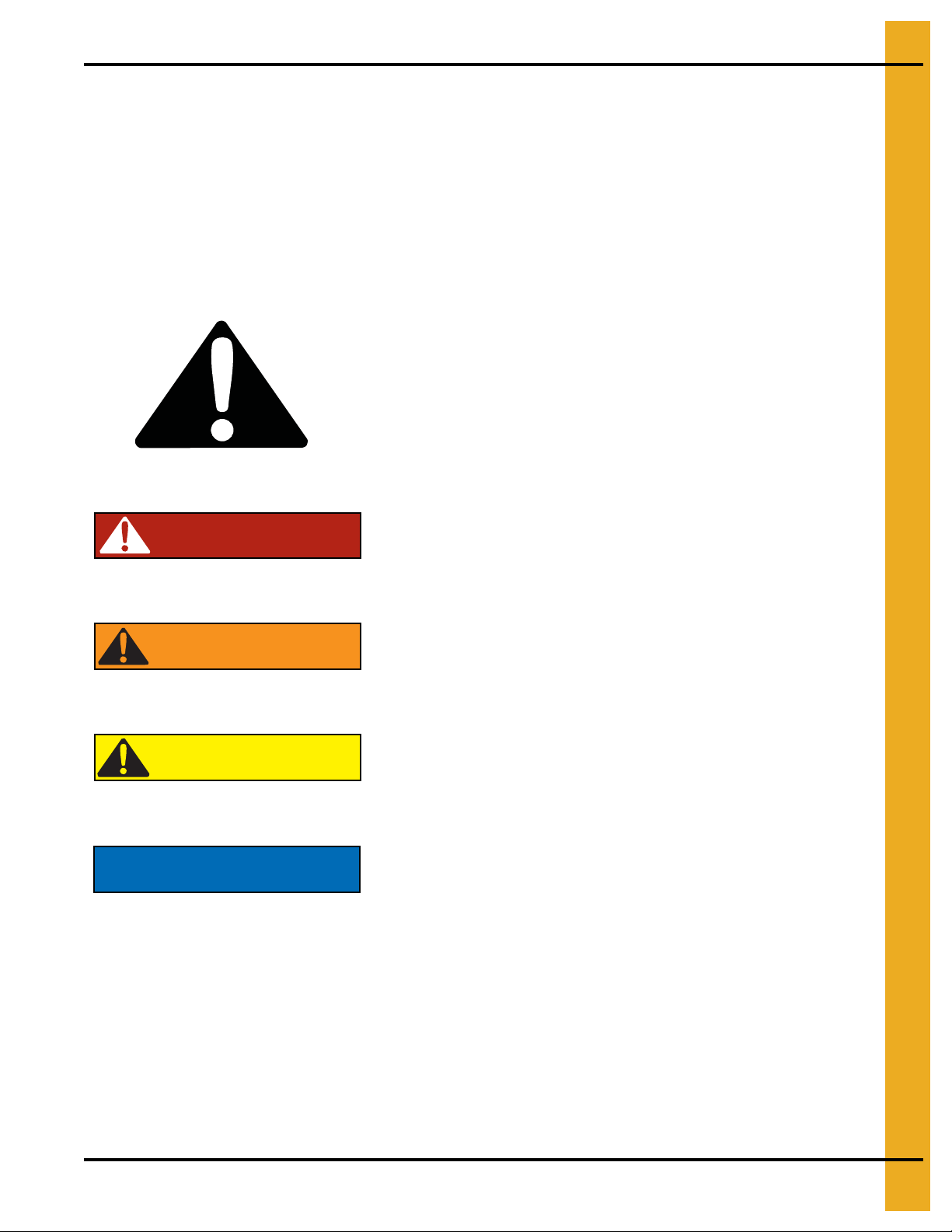
This is the safety alert symbol. It is used to alert you
to potential personal injury hazards. Obey all safety
messages that follow this symbol to avoid possible
injury or death.
WARNING indicates a hazardous situation which, if not
avoided, could result in death or serious injury.
CAUTION, used with the safety alert symbol, indicates a
hazardous situation which, if not avoided, could result in
minor or moderate injury.
NOTICE is used to address practices not related to
personal injury.
DANGER indicates a hazardous situation which, if not
avoided, will result in death or serious injury.
Safety Guidelines
This manual contains information that is important for you, the owner/operator, to know and understand.
This information relates to protecting personal safety and preventing equipment problems. It is the
responsibility of the owner/operator to inform anyone operating or working in the area of this equipment
of these safety guidelines. To help you recognize this information, we use the symbols that are defined
below. Please read the manual and pay attention to these sections. Failure to read this manual and its
safety instructions is a misuse of the equipment and may lead to serious injury or death.
PNEG-588-04 Deluxe Downwind Heater Installation and Operation 5
Page 6
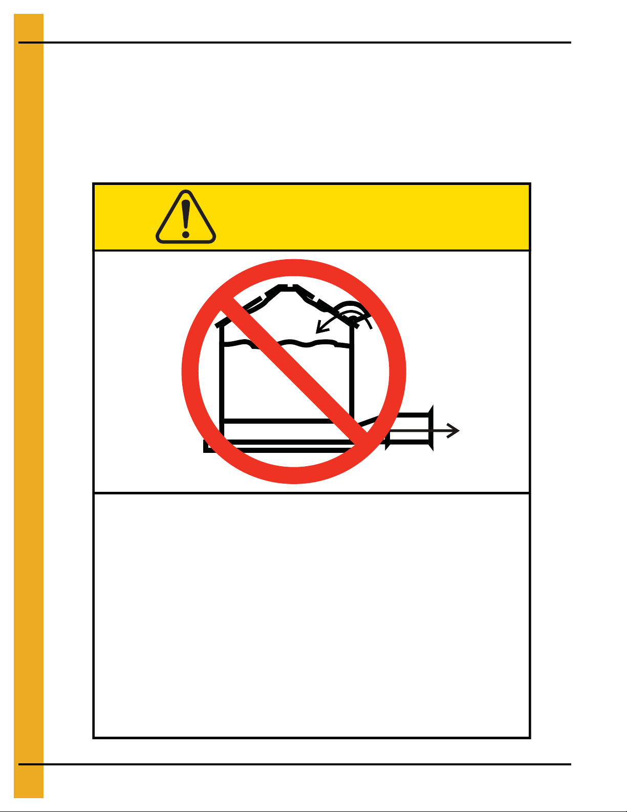
3. Decals
Excessive vacuum (or pressure) may
damage roof. Use positive aeration
system. Make sure all roof vents are
open and unobstructed. Start roof
fans when supply fans are started.
Do not operate when conditions exist
that may cause roof vent icing.
DC-969
CAUTION
GSI Group, Inc. 217-226-4421
Roof Damage Warning and Disclaimer
The manufacturer does not warrant any roof damage caused by excessive vacuum or internal
pressure from fans or other air moving systems. Adequate ventilation and/or “makeup air” devices
should be provided for all powered air handling systems. The manufacturer does not reco mmend
the use of downward flow systems (suction). Severe roof damage can result from any block age of
air passages. Running fans during high humidity/cold weather conditions can cause air exhaust
or intake ports to freeze.
6 PNEG-588-04 Deluxe Downwind Heater Installation and Operation
Page 7
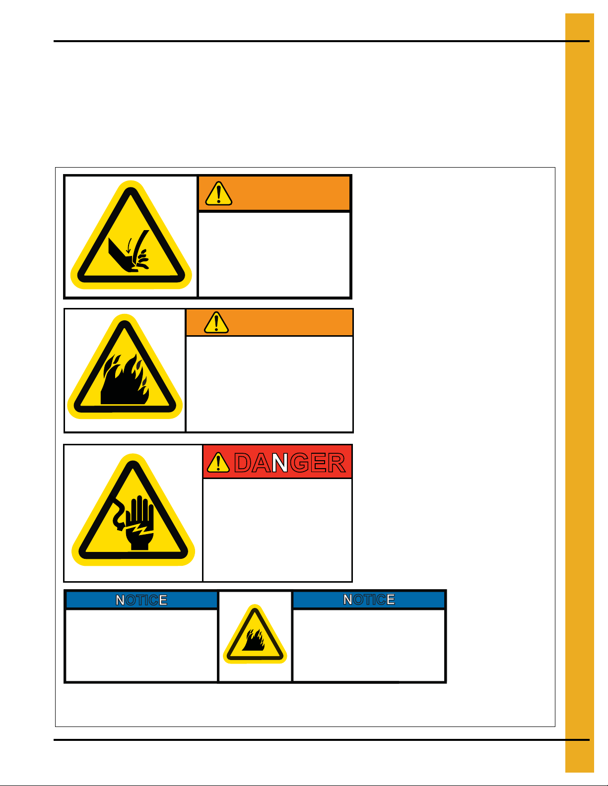
3. Decals
Stay clear of rotating
blade. Blade could start
automatically. Can cause
serious injury. Disconnect
power before servicing.
DC-1225GSI Group 217-226-4421
WARNING
DANGER
HIGH VOLTAGE
Will cause injury
or death.
Lockout power
before servicing.
DC-889
GSI Group Inc. 217-226-4421
Thermostat must be installed for
operation.
Failure to do so may damage
equipment and cause fire.
DC-1702
NOTICE
NOTICE
Le thermostat doit être installé
pour fonctionner.
Omettre cette installation peut
endommager l’équipement et
provoquer un feu.
GSI Group 217-226-4421
Part #: DC-1225
Size: 4-7/8" x 2-1/4"
Located above access door on heater housing.
(See Note Below.)
Part #: DC-1227
Size: 4-7/8" x 2-1/4"
Located above access door on heater housing.
(See Note Below.)
NOTE: May be substituted with
DC-1559 combination decals.
Part #: DC-889
Size: 2.813" x 1.375"
Located inside control box.
Part #: DC-1702
Size: 1-1/2" x 3-1/4"
Located on the outside of the control box lid.
Safety decals should be read and understood by all people in the grain handling area. If a decal is
damaged or is missing contact:
GSI Decals
1004 E. Illinois St.
Assumption, IL. 62510
Phone: 1-217-226-4421
A free replacement will be sent to you.
GSI Group 217-226-4421
WARNING
Flame and pressure beyond
door. Do not operate with
service door removed. Keep
head and hands clear. Can
cause serious injury.
DC-1227
PNEG-588-04 Deluxe Downwind Heater Installation and Operation 7
Page 8
3. Decals
DANGER
DC-1224
High voltage.
Will cause serious
injury or death.
Lockout power
before servicing.
Part Number: DC-1224
Size: 2-5/8" x 4-5/8"
Located on the outside of the control box lid.
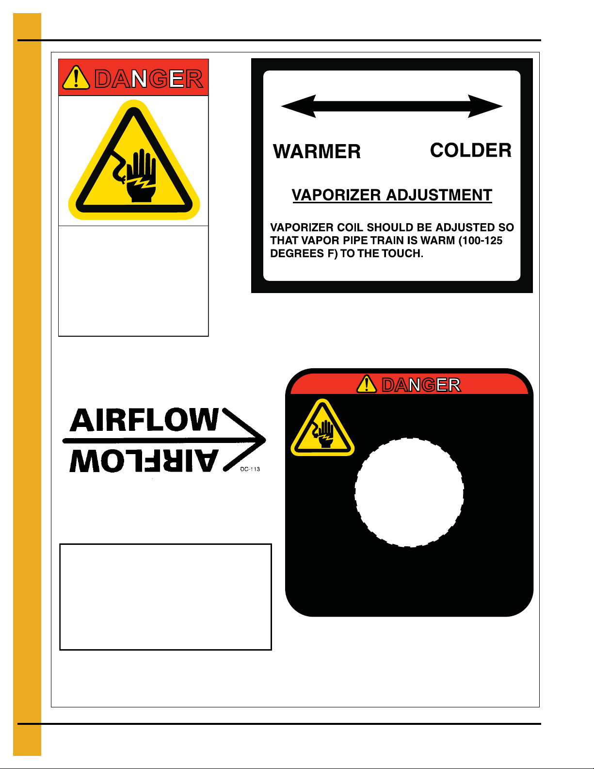
Part #: DC 113
Size: 4-3/4" x 1-5/8"
Located above access door on heater housing.
Part #: DC 1 165
Size: 3-1/4" x 3-1/4"
Located on the outside of the transition high-limit assembly.
DC-108
Hi-Limit
Reset Button
Part #: DC-108
Size: 1.0" x 2.0"
Located in control box next to housing high-limit switch.
DC-535
Part #: DC-535
Size: 2-1/2" x 3.0"
Located on the outside of the heater housing near
the vaporizer coil on LP units.
DANGER
HIGH VOLTAGE.
Will cause injury or death.
Lockout power before servicing.
HAUTE TENSION.
Causera des blessures ou la mort.
Fermez le courant avant l’entretien.
Remove plug to
reset high limit.
Enlevez le contact pour
reinitialiser la limite élévée.
DC-1165
8 PNEG-588-04 Deluxe Downwind Heater Installation and Operation
Page 9
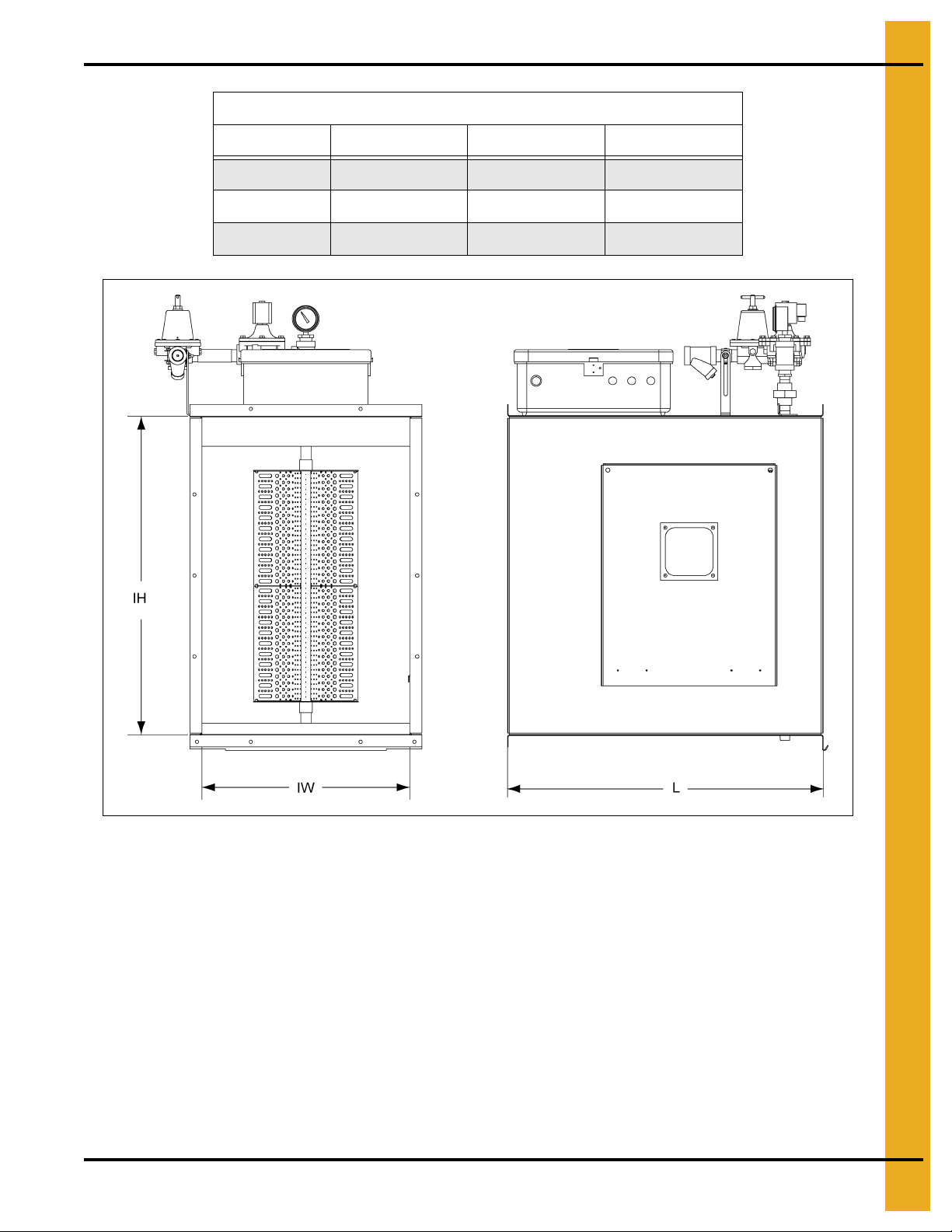
Heater Dimensions
Model # IH IW L
CHD-15 30-1/4" 19-1/2" 33.00"
CHD-30 33-1/4" 21-3/4" 33.00"
CHD-40 33-1/4" 23.69" 33.00"
4. Specifications
Figure 4A
PNEG-588-04 Deluxe Downwind Heater Installation and Operation 9
Page 10
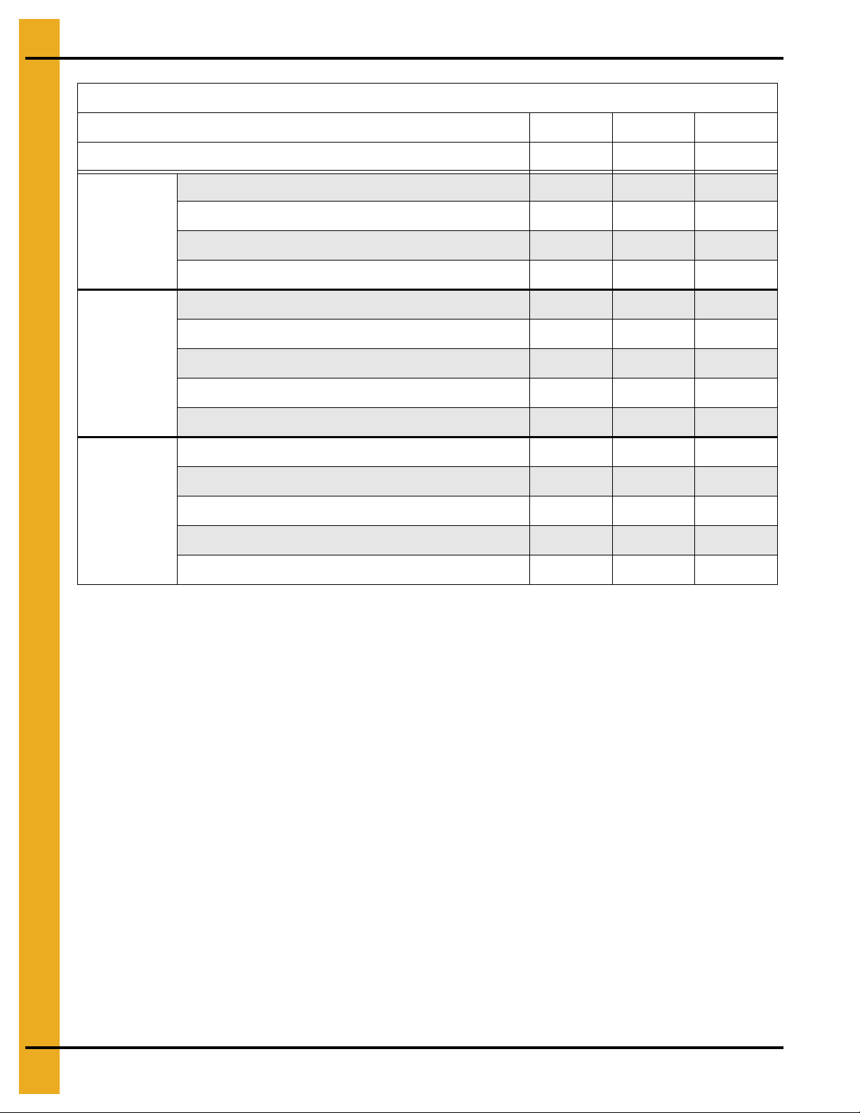
4. Specifications
Fuel Specifications and Recomme nd ati ons
Liquid
Propane
Models (LP)
Propane
Vapor
Models (VN)
Natural Gas
Models (VN)
Model #
BTU Rating
Orifice Size 7/32" 17/64" 5/16"
Operating Pressure Range, Heater Gauge Pressure (PSI) **
Typical Maximum Fuel Flow (GPH) * 25 36 46
Minimum Liquid Line Size 1/2" 1/2" 1/2"
Orifice Size 7/32" 17/64" 5/16"
Operating Pressure Range, Heater Gauge Pressure (PSI) **
Typical Maximum Fuel Flow (CFH) * 961 1379 1755
Minimum Line Size, 100' Run
Minimum Pressure to Heater at Connection (PSI) 20 20 20
Orifice Size
Operating Pressure Range, Heater Gauge Pressure (PSI) ** 1-7 1-7 1-7
Typical Maximum Vapor Fuel Flow (CFH) *
Minimum Line Size, 100' Run 1.0" 1.0" 1-1/4"
CHD-15 CHD-30 CHD-40
2,300,000 3,300,000 4,200,000
1-15 1-15 1-15
1-15 1-15 1-15
1.0" 1.0" 1-1/4"
21/64" 25/64" 7/16"
2212 3173 4038
Minimum Pressure to Heater at Connection (PSI)
* Maximum fuel flow rates listed assume full heat output for gas line sizing purposes. In normal operation, the fuel flow rates
would be substantially lower than indicated, due to actual pressure setting used and cycling of the burner.
** The gas pressures listed show the operating limits for each model heater and are not necessarily the recommended
operating pressure. The actual gas operating pressure should be within these limits, but will vary depending on the type
of grain and the drying system. The maximum setting assumes ideal conditions of relatively low static pressure conditions
with high fan airflow and good quality combustion. High static pressure conditions will require lower maximum gas pressure
setting than specified.
10 10 10
10 PNEG-588-04 Deluxe Downwind Heater Installation and Operation
Page 11
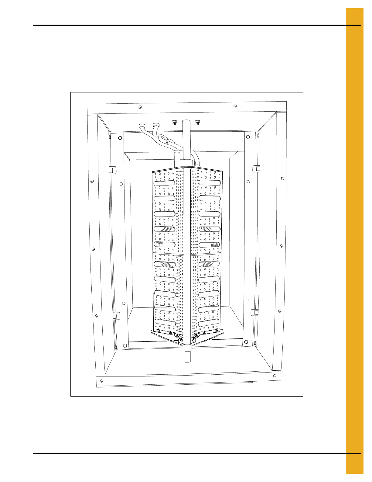
5. Installation
Vertical Profile Angle Configuration
Vertical profile angles have been added to the Downwind Centrifugal Heaters to increase burner
performance quality. These angles have been factory installed with the angle configuration of the smallest
horsepower fan rated for the heater. As a result, some changes will be require d at the time o f installation
once the fan and heater combination is known. This document describes the proper configurations of the
vertical angles inside the heater housing.
Figure 5A
IMPORTANT: Use of the vertical profile angles requires that the upper and lower pro file angles have their
90° bend on the window side of the heater as shown in Figure 5A.
PNEG-588-04 Deluxe Downwind Heater Installation and Operation 11
Page 12
5. Installation
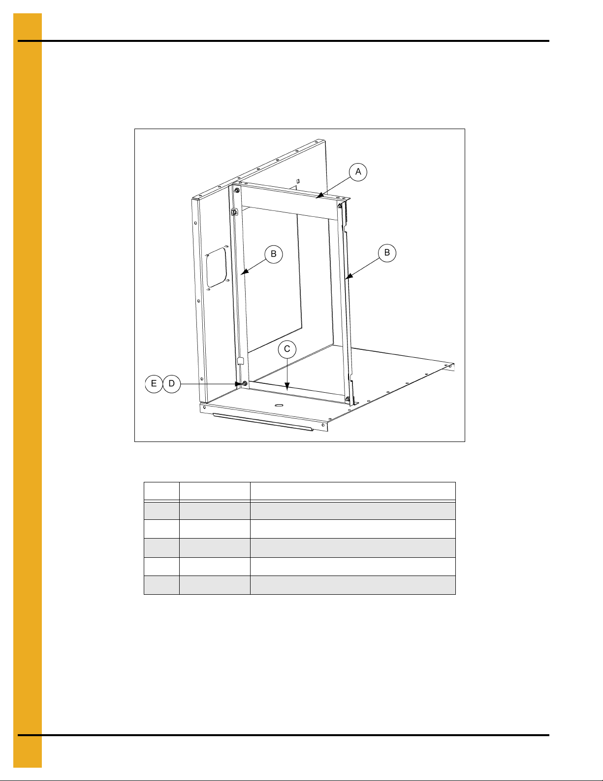
CF-10 Centrifugal Fan and CHD-15 Model Heater
Figure 5B shows the factory configuration. No change is required to the heater.
Retrofit applications require holes to be drilled in the upper and lower profile angles and the vertical angle
to be installed with the noted hardware.
Figure 5B CHD-15 Heater
Ref # Part # Description
A Upper Angle
B HF-8076 Profile Angle - Side for CHD-15 (2)
C Lower Angle
D S-3611 Flange Nut 5/16"-18 YDP Grade 2 (4)
E S-6606 Flange Bolt 5/16"-18 x 3/4" ZN Grade 5 (4)
CF-15 Centrifugal Fan and CHD-15 Model Heater
The vertical profile angles must be removed for correct operation of the heater.
12 PNEG-588-04 Deluxe Downwind Heater Installation and Operation
Page 13
5. Installation
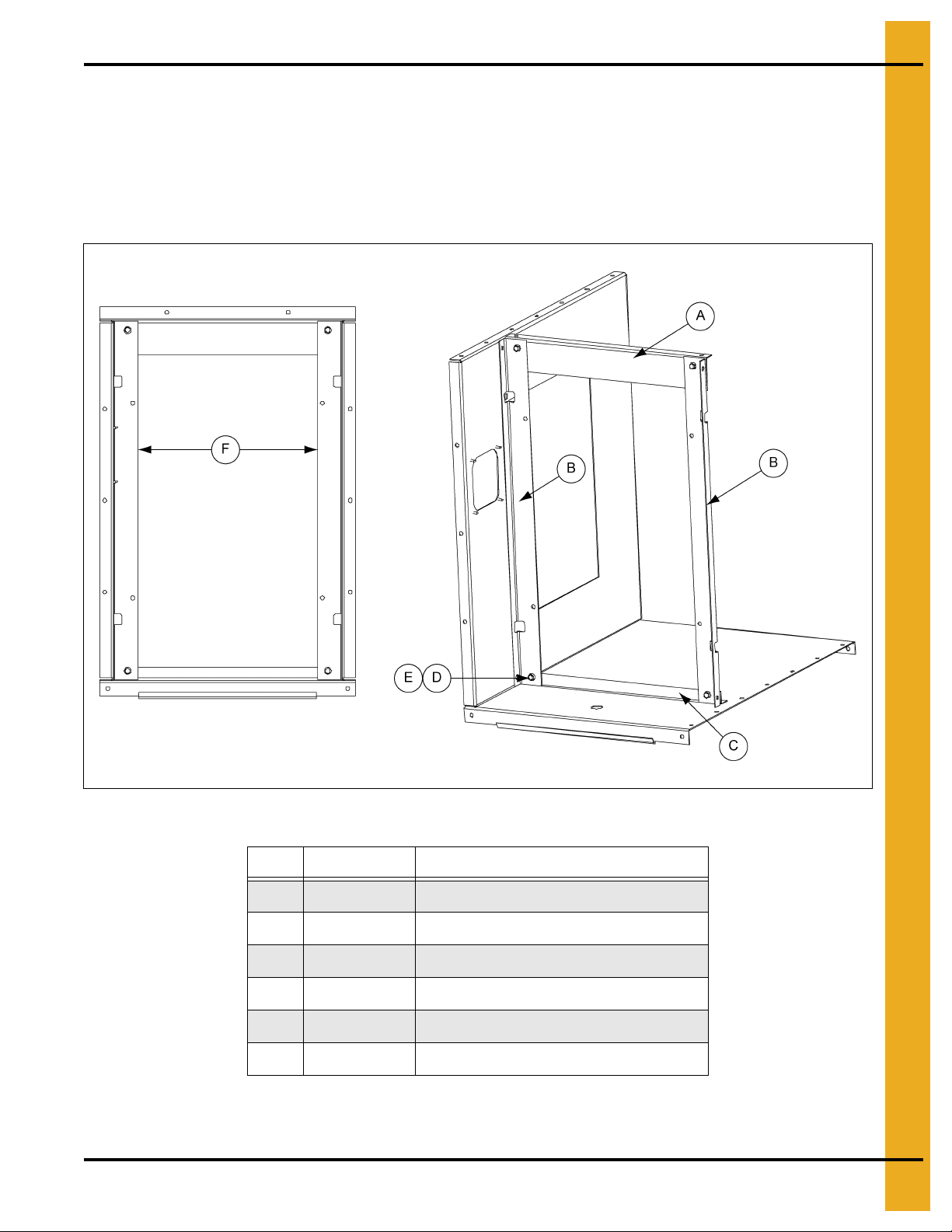
CF-20 Centrifugal Fan and CHD-30 Model Heater
Figure 5C shows the factory configuration for the 20 HP application. Here the long leg of the angle points
toward the center of the heater to provide a 17" wide opening across the housing at the location of the
angles. No change is required to the heater.
Retrofit applications require holes to be drilled in the upper and lower profile angles and the vertical profile
angles to be installed with the noted hardware.
Figure 5C CHD-30 Heater for CF-20 Fan
Ref # Part # Description
A Upper Angle
B HF-8071 Profile Angle - Side for CHD-30 (2)
C Lower Angle
D S-3611 Flange Nut 5/16"-18 YDP Grade 2 (4)
E S-6606 Flange Bolt 5/16"-18 x 3/4" ZN Grade 5 (4)
F 17"
PNEG-588-04 Deluxe Downwind Heater Installation and Operation 13
Page 14
5. Installation
Always disconnect and lock out power before working on or around heater.
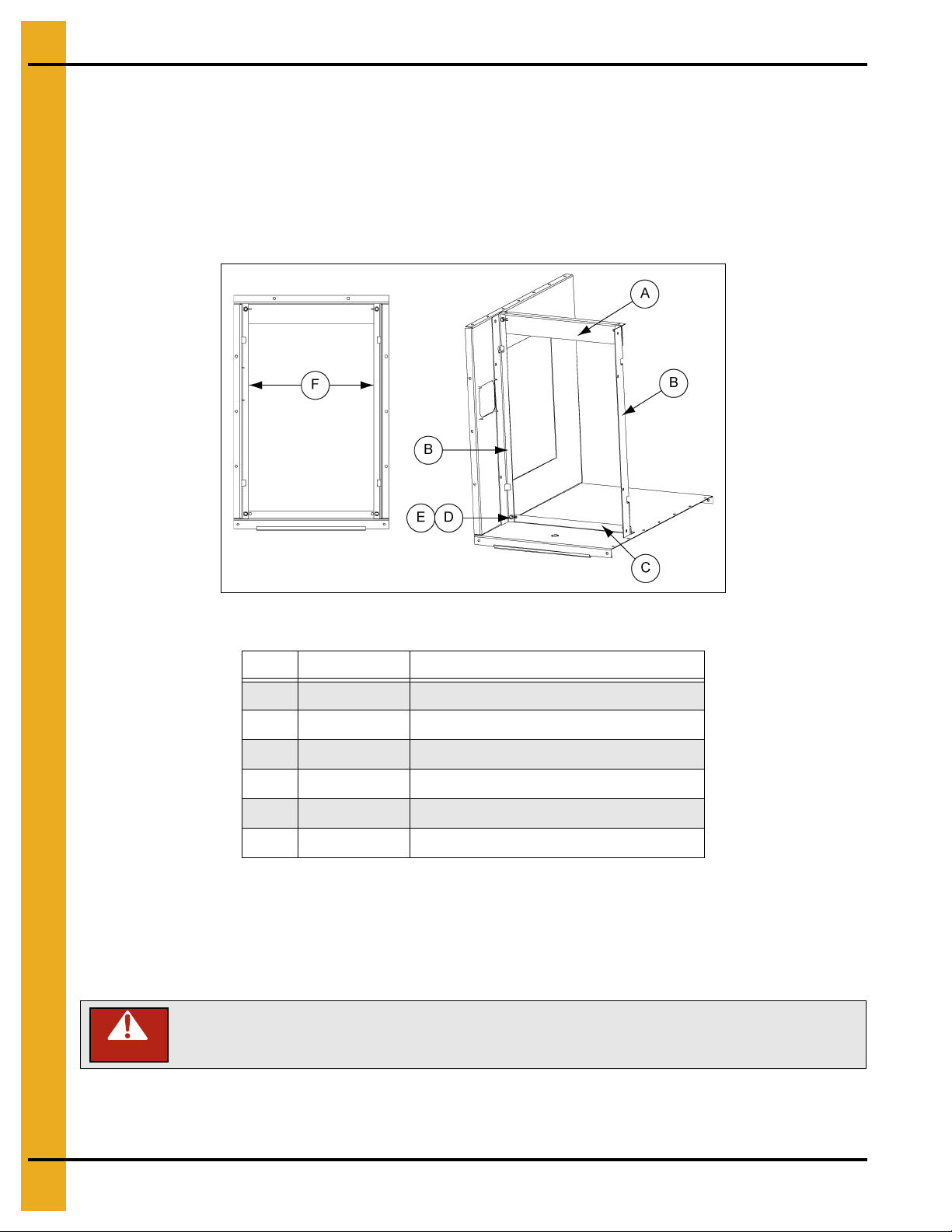
CF-25 Centrifugal Fan and CHD-30 Model Heater
Figure 5D shows the configuration for the 25 HP application. The vertical profile angles must be
repositioned. Flip each angle end for end and install it with the short leg of the angle pointing toward the
center of the heater. This provides a 19-1/2" wide opening across the heater housing at the location of
the angles.
Retrofit applications require holes to be drilled in the upper and lower profile angles and the vertical profile
angles to be installed with the noted hardware.
Figure 5D CHD-30 Heater for CF-25 Fan
Ref # Part # Description
A Upper Angle
B HF-8071 Profile Angle - Side for CHD-30 (2)
C Lower Angle
D S-3611 Flange Nut 5/16"-18 YDP Grade 2 (4)
E S-6606 Flange Bolt 5/16"-18 x 3/4" ZN Grade 5 (4)
F 19-1/2"
CF-30 Centrifugal Fan and CHD-30 Model Heater
The vertical profile angles must be removed for correct operation of the heater.
Deluxe Heater Electrical Installation
DANGER
Standard electrical safety practices and codes should be used when working with a heater. Refer to the
National Electric Code Standard handbook by the National Fire Protection Association. A qualified
electrician should make all wiring installations.
14 PNEG-588-04 Deluxe Downwind Heater Installation and Operation
Page 15
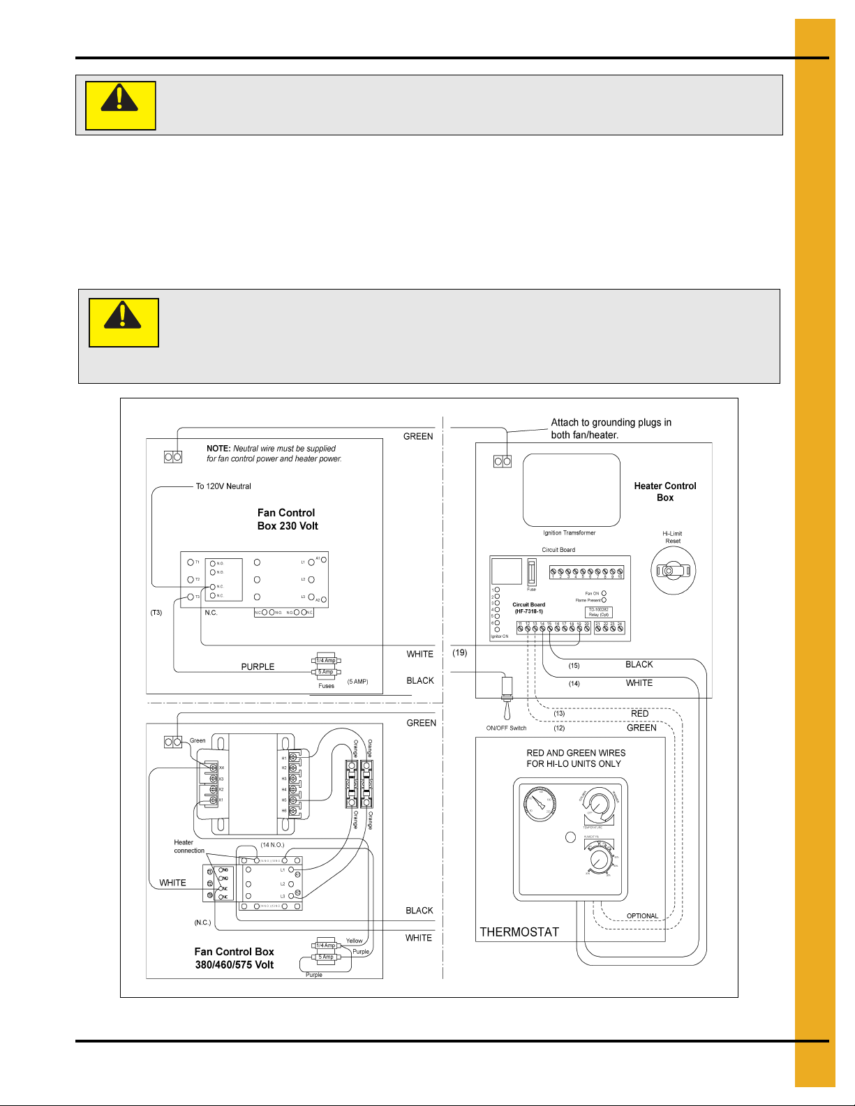
Heater Power Connection
CAUTION
Heater must be interlocked with fan for safe operation.
Thermostat must be installed for safe operation.
Heater power is 120 VAC. Damage will occur if connected to high voltage
power source.
1. Connect power cord to fan control box.
2. Make field connections in fan box as shown in Figure 5E.
3. Connect deluxe thermostat control as shown in Figure 5E.
NOTE: Heater control is 120V only.
CAUTION
5. Installation
PNEG-588-04 Deluxe Downwind Heater Installation and Operation 15
Figure 5E
Page 16

5. Installation
Deluxe Heater - Second Heater Installation
For Deluxe Units Using HF-7318-1 Control Board
Two (2) Deluxe Heaters may be connected to one grain drying system and wired so they cycle together.
One of the heaters should have a thermostat connected to it as per the installation instructions. That
heater will be referred to as the master. The other heater (without the thermostat) will be referred to
as the slave.
Installation for ON/OFF Units
1. Install relay base (TD-100283) in master heater control box.
2. Connect wire between terminal 6 on circuit board and terminal 14 on relay base in master heater.
3. Connect wire between terminal 13 on relay base and terminal 8 on circuit board in master heater.
4. Run two (2) wires (18 gauge) between master and slave heaters.
5. Connect wires to terminal 5 and 9 (points A and B) on relay base in master heater.
6. Connect wire from terminal 9 in master to terminal 14 (point F) in slave unit.
7. Connect wire from terminal 5 in master to terminal 15 (point E) in slave unit.
8. Install relay (TD-100282) in relay base.
Additional Steps for High-Low Units
1. Run two (2) wires (18 gauge) between master and slave unit.
2. Connect wires to terminals 21 and 22 (points C and D) on circuit board in main heater.
3. Connect wire from terminal 21 in master to terminal 12 (point H) in slave unit.
4. Connect wire from terminal 22 in master to terminal 13 (point G) in slave unit.
5. Install relay (TD-100282) in relay base.
Figure 5F The Control Board (HF-7318-1)
16 PNEG-588-04 Deluxe Downwind Heater Installation and Operation
Page 17
5. Installation
Do not use propane tanks which have previously been used for ammonia unless
they have been purged according to procedures of the national LP association.
Investigate to be sure that the fuel supply sys tem complies with all loca l codes for
LP gas installations.
CAUTION
Do not use flame for leak testing.
Fuel Connection
Liquid Propane Models
1. LP models are designed to run on liquid propane, with liquid draw from the propane tank. Avoid using
propane supply tanks that have been use for vapor draw for long pe riods of time. When u sing liquid
draw systems any moisture that may be present in tank or lines may freeze when system is used in
cold weather. To avoid this, the usual precaution is to purge the system with methanol.
2. Run proper size line (See Specifications on Page 9) to pipe train on heater. Have a qualified gas
service person inspect installation to be sure everything is installed according to local codes
and ordinances.
3. After installation is complete, check all connections for leaks. Use liquid detergent or comparable
substance. Wear rubber gloves and eye protection. Avoid contact with liquid propane.
DANGER
Propane Vapor Models
1. Propane vapor models are designed to run directly off of supply tank or from a separate
external vaporizer.
2. Run proper size line (See Specifications on Page 9) to pipe train on heater. Have a qualified gas
service person inspect installation to be sure everything is installed according to local codes
and ordinances.
3. After installation is complete, check all connections for leaks.
Natural Gas Models
1. Natural gas models are similar to vapor models, but have a larger orifice to accommodate lower
pressure, sometimes found with natural gas.
2. Run proper size line (See Specifications on Page 9) to pipe train on heater. Have a qualified gas
service person inspect installation to be sure everything is installed according to local codes
and ordinances.
3. After installation is complete, check all connections for leaks.
PNEG-588-04 Deluxe Downwind Heater Installation and Operation 17
Page 18

5. Installation
Bin Configuration
Figure 5G
Ref # Description
A Unload Auger
B Plenum Thermostat
C Master Heater
D Slave Heater
IMPORTANT: When mounting two (2) heaters on a bin it is imperative that they be situated as shown in
Figure 5G. Plenum thermostat must be to the right of master heater and master heater must
be to the right of slave heater.
18 PNEG-588-04 Deluxe Downwind Heater Installation and Operation
Page 19

Transition High-Limit Installation
1. Mark location on transition one foot up from the bottom (entrance collar) and centered in
the transition.
2. Drill or knock out 7/8" diameter hole on marked location.
3. Install transition high-limit using supplied self-drilling screws.
5. Installation
Figure 5H Sensor placement on transition connecting heater to the bin.
PNEG-588-04 Deluxe Downwind Heater Installation and Operation 19
Page 20

5. Installation
CAUTION
Thermostat must be installed to operate as plenum high-limit safety.
Plenum Thermostat Installation
The plenum thermostat must be ordered separately from the heater unit.
1. Follow installation instructions provided with the thermostat assembly.
2. Position the housing so that the bolt flanges are vertical and the cord exits the housing from the
bottom. Mark position.
3. Use six (6) (4.00") or eight (8) (2.66") self-drilling screws to mount the housing to the bin sidewall.
DO NOT TIGHTEN COMPLETELY. Insert corrugation seal into gap between housing and sidewall.
Tighten screws.
4. Caulk between the housing and the sidewall to seal.
Heater control device (thermostat or humidistat) is required for heater warranty on all heaters.
Figure 5I Plenum thermostat mounted on bin wall.
Figure 5J Side view of thermostat showing
corrugation seal.
20 PNEG-588-04 Deluxe Downwind Heater Installation and Operation
Page 21

6. Operation
CAUTION
Do not exceed plenum temperatures listed in table
Do not operate above rated maximum BTU output. Fire damage to grain product
and drying structure will occur. Refer to burner specifications for maximum BTU.
Operating Temperature Table
NOTE: This table is not intended as a d rying guide. It should be used as a reference for setting maximum
plenum temperature for safe operation.
Grain
Corn
Rice
Beans and
Wheat
Low Temperature
Batch
5-20°Above
Ambient Temperature
5-10°Above
Ambient Temperature
5-20°Above
Ambient Temperature
High Temperature
Batch Dry No Stirring
120° 140° 140°
100° 100° Not Recommended
110° 120° Not Recommended
High Temperature
with Stirring
CAUTION
Cycling Heater Operation
1. Thermostat must be wired into heater control box for heater to operate.
Continuous Flow
(Recirculating)
2. Open all manual shut off valves to heater unit.
3. Start fan. This will supply power to heater.
4. Turn thermostat dial to its highest setting.
5. Turn toggle switch ON.
6. Heater should now be lit. If not check to see that all gas is ON.
7. Watch thermometer on plenum and when it reaches desired temperature turn thermostat back slowly
until heater cycles OFF.
8. Gas pressure should be adjusted, so burner is on 75% of the time.
9. Watch plenum temperature as burner goes through a few cycles, to be sure that it is
operating properly.
PNEG-588-04 Deluxe Downwind Heater Installation and Operation 21
Page 22

6. Operation
High-Low Heater Operation
1. High-limit and cycling thermostat must be wired into heater control box for heater to operate.
2. Open all manual shut off valves to heater unit.
3. Start fan. This will supply power to heater.
4. Turn thermostat dial to its highest setting.
5. Turn toggle switch ON. Both indicator lights should illuminate indicating power to the control circuit.
6. Heater should now be lit. If not check to see that all gas is ON.
7. Loosen the retaining nut holding bypass valve screw in place. Open the bypass valve all the way.
8. Turn thermostat dial back slowly until heater cycles to low flame.
9. Adjust bypass valve so that low-flame pressure is at desired setting. (As low as possible.)
10. Turn thermostat dial to desired setting and wait for bin plenum to come up to temperature. Heater
should cycle to low flame after a few minutes.
11. If heater does not cycle to low flame increase high flame gas pressure by adjusting the regulator.
12. High flame should be adjusted, so the heater cycles at least once a minute. Low flame should be
adjusted so there is enough flame for unit to keep operating.
13. Watch as burner goes through a few cycles, to be sure that it is o perating properly back to high flame.
Figure 6A
Ref # Description
A Bypass Valve
B Retaining Nut
C Bypass Valve Screw
22 PNEG-588-04 Deluxe Downwind Heater Installation and Operation
Page 23

6. Operation
Modulating Valve Operation
1. The modulating valve regulates gas flow through the heater based on sensing unit in the plenum and
maintains a constant drying air temperature.
2. The sensing bulb of the modulating valve should be mounted through the bin wall with the side
reading “top” up. The bulb reacts to temperature. It changes the amount of gas (increase or
decrease), burning warmer or cooler depending on the position of the valve SET POINT. If the bulb
is cooler than it was at the SET POINT, the bulb senses the cooler temperature and opens the valve
further so more heat is applied to the drying air. If the bulb is warmer than it was at the SET POINT,
the valve closes further and reduces the temperature until the air is at the valve SET POINT.
3. It is important that the pressure regulator be set high enough to allow the modulating valve to deliver
enough gas to maintain the plenum temperature necessary. The regulat or is normally factory set at
15 PSI (propane units). To set the regulator, run the heater and turn the mo dulating valve T-handle
in. This gets full line pressure to the burner. Then adjust regulator to read 15 PSI (depending on the
plenum temperature needed).
4. Turn the fan and heater ON. To set the modulating valve, turn the T-handle out (counterclockwise)
until loose and wait a few minutes for the plenum temperature to equalize. When the temperature
under the bin has equalized, gradually turn T-handle in (clockwise) about 1/2 turn at a time. Wait until
temperature under bin has equalized as before. If temperature under bin is less than the desired
temperature, continue turning T-handle in, increasing gas flow and waiting for plenum temperature
to equalize until the desired temperature is the stable temperature of the plenum. If temperature
under bin is the same 10 minutes after you last made any adjustments to the T-handle you can be
certain that the temperature under the bin is the SET POINT of the valve. 1 Turn of the T-handle
equals approximately 7°F of temperature.
5. The valve will now keep the plenum temperature at the set point regardless of ambient conditions as
long as humidistat or thermostat do not shut down the heater. A bypass orifice is used to maintain a
small flame when outside temperature is near or above the set point of the valve. The bypass insures
steady application of heat at minimum gas flow operation. By pass orifice will only operate correctly
if pressure regulator is set correctly.
6. To observe how the modulating valve increases the efficiency of bin drying, check the gas pressure
of the unit in the morning and compare to the pressure read mid-afternoon. If the ambient (outside)
temperature is significantly greater later in the day (as normal), the ga s p r essure will be less. Sin ce
less heat is required to maintain the same temperature in the plenum, the modulating valve will have
reduced the amount of gas used by the heater.
PNEG-588-04 Deluxe Downwind Heater Installation and Operation 23
Page 24

6. Operation
BTU per Gauge Pressure - Propane
BTU Per Gauge Pressure - Propane (Approximate)
Gauge Pressure (PSI) 10-15 20-30 40-50
1 576,713 847,122 1,174,963
2 816,013 1,203,679 1,663,135
3 997,881 1,469,302 2,034,050
4 1,148,640 1,694,244 2,345,140
5 1,287,434 1,895,256 2,622,728
6 1,409,477 2,077,124 2,878,779
7 1,524,341 2,244,634 3,108,507
8 1,632,026 2,404,965 3,328,663
9 1,725,353 2,541,366 3,520,103
10 1,825,859 2,687,339 3,721,115
11 1,995,762 2,938,604 4,068,100
12 2,153,700 3,173,118 4,393,548
13 2,227,883 3,280,803 4,541,914
24 PNEG-588-04 Deluxe Downwind Heater Installation and Operation
Page 25

6. Operation
Gauge Pressure Required to Maintain Temperature Rise - Propane
Gauge Pressure (PSI) Required to Maintain Temperature Rise (Approximate)
Propane - High Temperature Units Only
Fan Model
10
15
20
25
Static Pressure
(Inches)
2 2 4 6 8 11
4 23569
6 2 2 3 5 6
2 36911
4 3 5 7 10 13
6 23579
2 3 4 6 9 11
4 245710
6 2 3 4 6 8
2 46913
4 3 5 8 11 15
6 346911
60 80 100 120 140
Heat Rise °F
30
40
50
2 4 7 10 15
4 46913
6 3 5 8 11 15
2 36911
4 3 5 8 11 13
6 347913
2 4 6 9 13
4 3581115
6 3 5 7 10 13
PNEG-588-04 Deluxe Downwind Heater Installation and Operation 25
Page 26

6. Operation
BTU per Gauge Pressure - Natural Gas
BTU Per Gauge Pressure - Natural Gas (Approximate)
Gauge Pressure (PSI) 10-15 20-30 40-50
1 893,360 1,264,640 1,587,040
2 1,266,720 1,794,000 2,250,560
3 1,548,560 2,192,320 2,750,800
4 1,785,680 2,529,280 3,173,040
5 1,996,800 2,827,760 3,548,480
6 2,191,280 3,102,320 3,891,680
7 2,367,040 3,351,920 4,204,720
26 PNEG-588-04 Deluxe Downwind Heater Installation and Operation
Page 27

Gauge Pressure Required to Maintain Temperature Rise Natural Gas
Gauge Pressure (PSI) Required to Maintain Temperature Rise (Approximate)
Natural Gas - High Temperature Units Only
6. Operation
Fan
Model
10
15
20
25
Static Pressure
(Inches)
2 1 2 3 4 5
4 12234
6 1 1 2 2 3
2 23457
4 1 2 3 4 6
6 12234
2 1 2 3 4 5
4 12345
6 1 2 2 3 4
2 2346
4 2 3 4 5 7
6 12346
60 80 100 120 140
Heat Rise °F
30
40
50
2 2 3 5 7
4 2346
6 2 3 4 5 7
2 2357
4 2 3 4 6
6 23457
2 2 4 5 7
4 2356
6 2 3 4 5 7
PNEG-588-04 Deluxe Downwind Heater Installation and Operation 27
Page 28
6. Operation
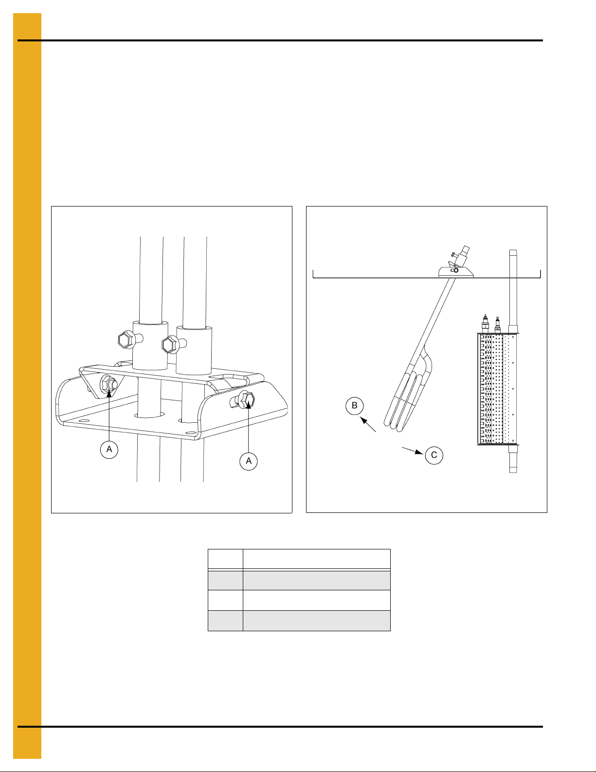
Adjusting the Vaporizer
1. Vaporizer should be adjusted so the vapor pipe train runs warm to the touch (100°-120°F).
2. Loosen 5/16" pivot bolts on adjustment bracket.
3. Tilt vaporizer away from burner to cool. Tilt toward burner to heat. Vaporizer may be raised or lowered
for vertical adjustments.
4. Tighten 5/16" pivot bolts to fix vaporizer position.
IMPORTANT: Only move vaporizer 1" at a time. Allow heater to run a few minutes for temperature
to equalize.
Figure 6B
Ref # Description
A Pivot Bolts
BCooler
C Warmer
Figure 6C
Vaporizer adjustment: Away from burner to cool. Toward burner to heat.
28 PNEG-588-04 Deluxe Downwind Heater Installation and Operation
Page 29

7. Service
Seasonal Inspection and Service
All parts are made of weather-proof construction and are designed to require a minimum of service;
however, we recommend the following items be checked and serviced, as described, before the unit is
used each season. Replace any damaged or questionable parts.
THESE CHECKS WILL HELP ELIMINATE POSSIBLE MINOR FAULTS AND ASSURE DEPENDABLE
OPERATION OF THE EQUIPMENT WHEN IT IS NEEDED.
1. Check fan and service it as described within the fan installation and operation manual.
2. Shut off electrical power. Remove heater control box cover and inspect for moisture, rodent damage
or accumulated foreign material remove any foreign material present. INSPECT AND TIGHTEN ALL
LOOSE TERMINAL CONNECTIONS. Replace any damaged or deteriorated wiring.
3. Shut off fuel and remove and clean gas line strainer.
4. Remove the orifice from the burner venturi and inspect for obstructions. Also, inspect and clean out
the burner venturi and the ports within the burner cup. Blow out with compressed air or disassemble
and thoroughly clean these parts. Foreign material in the venturi or burner cup will impair heater
operation and cannot be expected to burn out when the heater is started.
5. Inspect and clean the electrodes on the ignitor plug. Use an ignition point file to remove carbon and
rust between the electrode surfaces.
6. Inspect flame rod and ignitor plug wires for possible damage or poor connections.
7. After completing all checks and performing any necessary service, check the control device, as
described under the following appropriate heading.
Heaters Equipped with a Humidistat Control
Temporarily remove humidistat control from air plenum chamber of bin. Rotate the knob through the
20% to 80% humidity range. The switch within the humidistat should produce a small “click” when the le ver
passes the point of prevailing humidity.
NOTE: For additional information, refer to instructions that accompanied the humidistat.
Heaters Equipped with a Thermostat Control
Slowly rotate the thermostat dial through its temperature range. The switch within the thermostat should
produce a small “click” when the dial passes the point of prevailing temperature. Set the dial to a setting
at least 10°F above the prevailing temperature and proceed to the next step.
8. Test operate the fan and heater. Make sure to follow operating instructions, INCLUDING. After fan
starts operating and the heater purge interval has elapsed (approximately 20 seconds delay), the
heater should come ON and start operating.
9. Slowly change the humidistat or thermostat setting and cycle the heater OFF and ON to make sure
the device is controlling the heater and is operating properly.
PNEG-588-04 Deluxe Downwind Heater Installation and Operation 29
Page 30

7. Service
10. LP MODELS ONLY - After heater has been operating for some time and temperatures have
stabilized, check temperature of the gas line between outlet side of vaporizer and the gas regulator.
If gas line becomes “frosted” with an accumulation o f ice build-u p, adjust vaporize r slightly closer to
the flame. If line reaches a high temperature where it is hot to the touch, adjust vaporizer further away
from the flame.
NOTE: If gas temperature exceeds approximately 220°F, the vapor high-limit thermostat will
open the electrical circuit to the liquid gas solenoid valve and shut off fuel flow to stop the
heater. This condition can be verified by temporarily connecting a jumper wire across the
connections of the high-limit and observing that the burner re-lights. If high-limit vapor
thermostat causes the burner to stop operating, it may also cause the burner to go into a
safety lock out condition. Refer to heater operating instructions for restarting procedure.
11. Vaporizers should be inspected and serviced prior to each season of operation, including
the following:
a. Carefully inspect the surfaces of the vaporizer coil and the inlet and vapor outlet pipes for
evidence of severe corrosion or abrasion of metal which could cause subsequent leakage of
liquid propane, gross overheating and fire hazard.
b. Insecure mounting of either the vaporizer or burner, due to loosened bolts, can cause interference
between burner vanes and vaporizer pipes, with the natural vibration of the unit causing erosion
of the pipe metal at the point of maintained contact.
c. If there has been significant abrasion of the steel vaporizer pipe, it must be replaced.
12. When satisfied that heater is operating properly, make sure to reset the control d evice to the p roper
setting and restore the fan and heater for normal type operation.
IMPORTANT: Use care when troubleshooting this product. Limit exposure to potential hazards by
following all recommended safety practices.
30 PNEG-588-04 Deluxe Downwind Heater Installation and Operation
Page 31

1. Heater Housing: CHD-15 - (See Page 32.)
2. Heater Housing: CHD-30 and CHD-40 - (See Page 33.)
3. Propane Vapor Pipe Train: All Models - (See Page 34.)
4. Liquid Propane Pipe Train: All Models - (See Page 35.)
5. Natural Gas Pipe Train: CHD-15 - (See Page 36.)
6. Natural Gas Pipe Train: CHD-30 and CHD-40 - (See Page 37.)
7. LP Supply Pipe Train - (See Page 38.)
8. 3/4" High-Low Pipe Train Option - (See Page 39.)
8. Parts List
9. 3/4" Modulating Pipe Train Option - (See Page 40.)
10. 1.0" Pipe Train Options: High-Low and Modulating - (See Page 41.)
11. Deluxe Heater Control Box - (See Pages 42-43.)
PNEG-588-04 Deluxe Downwind Heater Installation and Operation 31
Page 32

8. Parts List
Heater Housing: CHD-15
Heater Housing: CHD-15 Parts List
Ref # Part # Description
1 HF-7653 Downwind Housing Bottom: 10-15
2 HF-7654 Downwind Housing Side: R.H. 10-15
3 HF-7652 Downwind Housing Top: 10-15
4 HF-7655 Downwind Housing Side: L.H. 10-15
5 HF-7854 Access Panel Downwind Heater - Blank
6 HF-7287 Access Panel Bracket - Downwind Heaters
7 HF-7379 Heater Cover Plate 1996<
8 HF-7380 Window Access 0.060 x 6 x 6 Plastic
9 HF-7662 Downwind Housing Profile Bottom: 10-15
10 HF-7661 Downwind Housing Profile Top: 10 -15
11 401-5369-4 Burner Mounting Bracket - CFDH
12 HF-7796 Cover Plate - Downwind Vaporizer Hole
13 415-4312-5 Burner Sub-Assembly CFDH27
14 THH-4179 Flame Sensor 6" Long Rod
15 HH-1650 Spark Plug Auburn #I-31
32 PNEG-588-04 Deluxe Downwind Heater Installation and Operation
Page 33

Heater Housing: CHD-30 and CHD-40
8. Parts List
Heater Housing: CHD-30 Parts List Heater Housing: CHD-40 Parts List
Ref # Part # Description Ref # Part # Description
1 HF-7781 Downwind Housing Bottom: 20-30 1 HF-7803 Downwind Housing Bottom: 40
2 HF-7783
3 HF-7780 Downwind Housing Top: 20-30 3 HF-7802 Downwind Housing Top: 40
4 HF-7784
5 HF-7854 Access Panel Downwind Heater - Blank 5 HF-7854 Access Panel Downwind Heater - Blank
6 HF-7287
7 HF-7379 Heater Cover Plate 1996< 7 HF-7379 Heater Cover Plate 1996<
8 HF-7380
9 HF-7786 Downwind Housing Profile Bottom: 20-30 9 HF-7805 Downwind Housing Profile Bottom: 40
10 HF-7785
11 401-5369-4 Burner Mounting Bracket - CFDH 11 401-5369-4 Burner Mounting Bracket - CFDH
12 HF-7796
13 415-4434-7 Burner Sub-Assembly CFDH30/33 13 415-4434-7 Burner Sub-Assembly CFDH30/33
14 THH-4179
Downwind Housing Side: R.H. 20-30/40 2 HF-7783 Downwind Housing Side: R.H. 20-30/40
Downwind Housing Side: L.H. 20-30/40 4 HF-7784 Downwind Housing Side: L.H. 20-30/40
Access Panel Bracket - Downwind Heaters 6 HF-7287 Access Panel Bracket - Downwind Heaters
Window Access 0.060 x 6 x 6 Plastic 8 HF-7380 Window Access 0.060 x 6 x 6 Plastic
Downwind Housing Profile Top: 20-30 10 HF-7804 Downwind Housing Profile Top: 40
Cover Plate - Downwind Vaporizer Hole 12 HF-7796 Cover Plate - Downwind Vaporizer Hole
Flame Sensor 6" Long Rod 14 THH-4179 Flame Sensor 6" Long Rod
15 HH-1650 Spark Plug Auburn #I-31 15 HH-1650 Spark Plug Auburn #I-31
PNEG-588-04 Deluxe Downwind Heater Installation and Operation 33
Page 34

8. Parts List
Propane Vapor Pipe Train: All Models
Propane Vapor Pipe Train: All Models Parts List
Ref # Part # Description Ref # Part # Description
1 HH-1251 Strainer, 1/2" Y 250# WOG SCH 80 12 707-1175-9 Union, 3/4" SCH 40 Black
2 007-1747-0 Plug, Pipe 1/4"
3 THH-4088 Nipple, 1/2" x 4" SCH 40 Black 14 HF-7794 Orifice Holder - Quad Heater - 3/4"
4 HH-1096 Clamp, 1/2" Conduit
5 HF-7575 Pipe Train Bracket: Downwind Unipipe 15 HF-7749 Orifice Plug (3/4) Drill: 17/64" (CHD-30)
6 TFC-0023-50 Regulator, 1/2" NPT - CSA 50 PSI
7 THH-4032 Nipple, 1/2" Close SCH 40 Black 16 007-1106-9 Tee, 1" x 1" x 3/4"
8 THH-4149 Elbow, 3/4"-1/2" Reduce SCH 40
9 HH-7101 Nipple, 3/4" x 6" SCH 40 Black 18 HH-2984 Gauge, Pressure 0-30# LP
10 056-2223-8 Solenoid Valve 3/4" NPT 115V Din
11 THH-4121 Nipple, 3/4" Close SCH 40 Black (CHD-15)
11 HH-7102 Nipple, 3/4" x 2-3/4" SCH 40 Black (CHD-30)
13 THH-4121 Nipple, 3/4" Close SCH 40 Black
15 HF-7 701 Orifice Plug (3/4) Drill: 7/32" (CHD-15)
15 HF-7 809 Orifice Plug (3/4) Drill: 5/16" (CHD-40)
17 THH-4001 Reducer, 1" x 1/4" Hex Bushing S40 BL
11 THH-4122 Nipple, 3/4" x 4-1/2" SCH 40 Black (CHD-40)
34 PNEG-588-04 Deluxe Downwind Heater Installation and Operation
Page 35

Liquid Propane Pipe Train: All Models
8. Parts List
Liquid Propane Pipe Train: All Models Parts List
Ref # Part # Description Ref # Part # Description
1 HF-7686 Pipe Train Asembly, LP Supply DW 04 17 THH-4149 Elbow, 3/4"-1/2" Reduce SCH 40
2 HF-7509 Hose, 1/2" x 18" LP Gas Assembly
3 HH-4847 Elbow, 1/2"-90° SCH 80 Black 19 056-2223-8 Solenoid Valve 3/4" NPT 115V Din
4 CD-0197 Vaporizor Coil for Downwind Heaters
5 410-1783-1 Vaporizer Adjusting Weldment 20 HH-7102 Nipple, 3/4" x 2-3/4" SCH 40 Black (CHD-30)
6 HF-7795 Pivot Bracket: Downwind Vaporizer 04
7 THH-4058 Tee, 1/2" x 1/2" x 1/2" SCH 80 Black 21 THH-4001 Reducer, 1" x 1/4" Hex Bushing S40 BL
8 HH-7013 Switch, Screw-In Vapor High-limit
9 THH-4071 Elbow, 1/2"-90° SCH 40 Black 23 007-1106-9 Tee, 1" x 1" x 3/4"
10 D07-0009 Hose, 3/8" x 24" LG LP Gas 350 Max
11 HH-1096 Clamp, 1/2" Condui t 25 THH-4121 Nipple, 3/4" Close SCH 40 Black
12 HF-7575 Pipe Train Bracket: Downwind Unipipe
13 THH-4071 Elbow , 1/2"-90° SCH 40 Black 27 HF-7701 Orifice Plug (3/4) Drill: 7/32" (CHD-15)
14 THH-4088 Nipple, 1/2" x 4" SCH 40 Black
18 D08-0020 Nipple, 3/4" x 6" SCH 80 Black
20 THH-4121 Nipple, 3/4" Close SCH 40 Black (CHD-15)
20 THH-4122 Nipple, 3/4" x 4-1/2" SCH 40 Black (CHD-40)
22 HH-2984 Gauge, Pressure 0-30# LP
24 707-1175-9 Union, 3/4" SCH 40 Black
26 HF-7794 Orifice Holder - Quad Heater - 3/4"
27 HF-7749 Orifice Plug (3/4) Drill: 17 /64" (CHD-30)
15 TFC-0023-50 Regulator, 1/2" NPT - CSA 50 PSI 27 HF-7809 Orifice Plug (3/4) Drill: 5/16" (CHD-40)
16 THH-4032 Nipple, 1/2" Close SCH 40 Black
PNEG-588-04 Deluxe Downwind Heater Installation and Operation 35
Page 36

8. Parts List
Natural Gas Pipe Train: CHD-15
Natural Gas Pipe Train: CHD-15 Parts List
Ref # Part # Description
1 D67-0008 Strainer, 3/4" Y 250# WOG SCH 80 Black
2 D07-0024 Plug, 1/2" Pipe Solid Black
3 D08-0018 Nipple, 3/4" x 4" SCH 40 Black
4 D62-0005 Clamp, 3/4" Conduit
5 HF-7575 Pipe T rain Bracket: Downwind Unipipe
6 D58-0002 Valve, 3/4" NPT Ball Shut Off
7 THH-4066 Elbow, 3/4"-90° Street SCH 40 Black
8 HH-7101 Nipple, 3/4" x 6" SCH 40 Black
9 056-2223-8 Solenoid Valve 3/4" NPT 115V Din
10 THH-4121 Nipple, 3/4" Close SCH 40 Black
11 707-1175-9 Union, 3/4" SCH 40 Black
12 THH-4121 Nipple, 3/4" Close SCH 40 Black
13 HF-7794 Orifice Holder - Quad Heater - 3/4"
14 HF-7708 Orifice Plug (3/4) Drill: 21/64"
15 007-1106-9 Tee, 1" x 1" x 3/4"
16 THH-4001 Reducer, 1" x 1/4" Hex Bushing S40 BL
17 D08-0022 Gauge, Pressure 0-15#
36 PNEG-588-04 Deluxe Downwind Heater Installation and Operation
Page 37

Natural Gas Pipe Tr ain: CHD-30 and CHD-40
8. Parts List
Natural Gas Pipe Train: CHD-30 and CHD-40 Parts List
Ref # Part # Description
1 TF-1283 Strainer, 1" Y
2 D07-0024 Plug, 1/2" Pipe Solid Black
3 THH-4059 Nipple, 1" x 5-1/2" SCH 40 Black
4 THH-4170 Clamp, 1" Conduit
5 HF-7575 Pipe Train Bracket: Downwind Unipipe
6 TFC-0093 Valve, 1" NPT Bronze Ball - CGA
7 THH-4164 Elbow, 1"-90° Street SCH 40 Black
8 THH-4059 Nipple, 1" x 5-1/2" SCH 40 Black (CHD-30)
8 007-11 10-1 Nipple, 1" x 7" (CHD-40)
9 056-2224-6 Solenoid Valve 1" NPT 115V Din
10 THH-4117 Nipple, 1" Close SCH 40 Black
11 707-1175-9 Union, 3/4" SCH 40 Black
12 THH-4121 Nipple, 3/4" Close SCH 40 Black
13 HF-7794 Orifice Holder - Quad Heater - 3/4"
14 HF-7750 Orifice Plug (3/4) Dr ill: 25/64" (CHD-30)
14 HF-7810 Orifice Plug (3/4) Drill: 7/16" (CHD-40)
15 THH-4137 Tee, 1" x 1" x 1" NPT SCH 40 Black
16 THH-4001 Reducer, 1" x 1/4" Hex Bushing S40 BL
17 D08-0022 Gauge, Pressure 0-15#
PNEG-588-04 Deluxe Downwind Heater Installation and Operation 37
Page 38

8. Parts List
LP Supply Pipe Train
LP Supply Pipe Train Parts List
Ref # Part # Description
1 HH-1251 Strainer, 1/2" Y 250# WOG SCH 80
2 007-1747-0 Plug, Pipe 1/4"
3 D07-0019 Nipple, 1/2" x 1-1/2" SCH 80 Black
4 007-1226-5 Ball Valve 1/2" w/ Lever Handle
5 HF-7586 Nipple, 1/2" x 2" SCH 80 Black
6 HH-1096 Clamp, 1/2" Conduit
7 HF-1026 Pipe Train Bracket: Vane Axial Heaters
8 TFC-0100 Valve, 1/2" NPT Solenoid LP w/ Din
9 TFC-0027 Valve, 1/4" NPT 250 PSI Relief
10 HH-4846 Tee, 1/2" x 1/2" x 1/4" SCH 80 Black
11 HH-1932 Elbow, 1/2" Pipe/1/2" Flare Brass
38 PNEG-588-04 Deluxe Downwind Heater Installation and Operation
Page 39
3/4" High-Low Pipe Train Option
8. Parts List
3/4" High-Low Pipe Train Option Parts List
Ref # Part # Description
1 D08-0020 Nipple, 3/4" x 6" SCH 40 Black
2 THH-4125 Nipple, 3/4" x 2" SCH 40 Black
3 056-2228-7 Solenoid Valve 3/4" NPT 115V Bypass
4 THH-4121 Nipple, 3/4" Close SCH 40 Black
PNEG-588-04 Deluxe Downwind Heater Installation and Operation 39
Page 40

8. Parts List
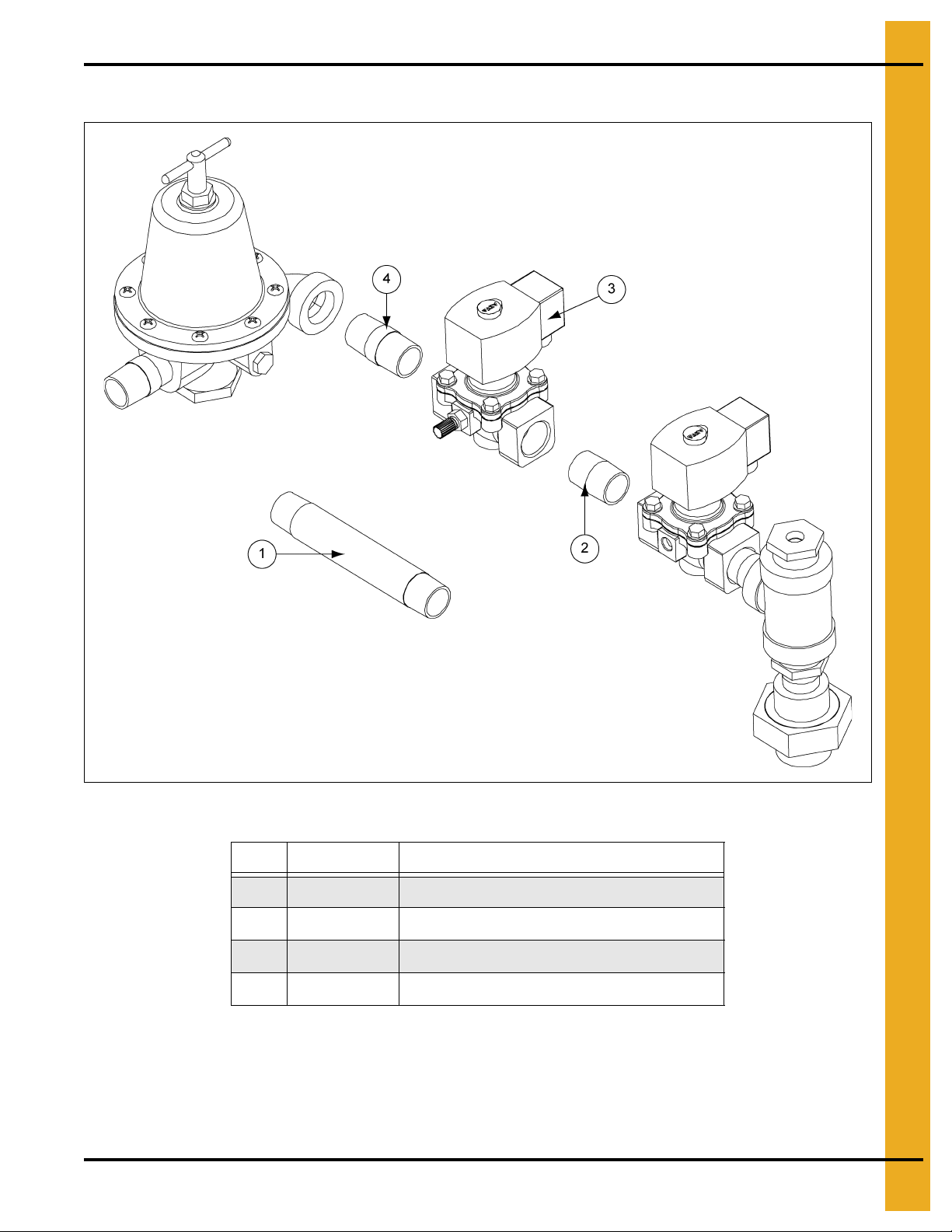
3/4" Modulating Pipe Train Option
3/4" Modulating Pipe Train Option Parts List
Ref # Part # Description
1 THH-4164 Elbow, 1"-90° Street SCH 40 Black
2 THH-4115 El bow, 1"-90° SCHED SCH 40 Black
3 THH-4151 Nipple, 1" x 3" SCH 40 Black
4 THH-4059 Nipple, 1" x 5-1/2" SCH 40 Black
High-Low or Modulating Valves can be ordered factory installed or added in the field. Field installation
requires the removal of the long pipe nipple (See Ref #1 on Page 39 ). Once removed, the components
for the appropriate valve should be added in the same location. Pipe sealant should always be used to
prevent leaks.
40 PNEG-588-04 Deluxe Downwind Heater Installation and Operation
Page 41

8. Parts List
1.0" Pipe Train Options: High-Low and Modulating
High-Low or Modulating Valves can be ordered factory installed or added in the field. Field installation
requires the removal of the 1" 90° street elbow (Ref #1). Once removed, the components for the
appropriate valve should be added in the same location. 1.0" Pipe train options will require additional
support brackets: HF-7575 and THH-4170. Pipe sealant should always be used to prevent leaks.
1.0" Pipe Train Options: High-Low and Modulating Parts List
Ref # Part # Description
1 THH-4164 Elbow, 1"-90° Street SCH 40 Black
2 THH-4115 Elbow, 1"-90° SCHED SC H 40 Bla ck
3 THH-4151 Nipple, 1" x 3" SCH 40 Black
4 THH-4059 Nipple, 1" x 5-1/2 " SCH 40 Black
5 THH-4151 Nipple, 1" x 3" SCH 40 Black
6 056-2230-3 Solenoid Valve 1" NPT 115V w/ Bypass
7 HF-7847 Valve, Mod 1-1/4" 90/210F 15' Cap
8 THH-4083 Reducer, 1-1/4 -1" Hex Bushing SCH
9 HF-7575 Pipe Train Bracket: Downwind Unipipe
10 THH-4170 Clamp, 1" Conduit
PNEG-588-04 Deluxe Downwind Heater Installation and Operation 41
Page 42

8. Parts List
Deluxe Heater Control Box
42 PNEG-588-04 Deluxe Downwind Heater Installation and Operation
Page 43

Deluxe Heater Control Box Parts List
Ref # Part # Description
1 HF-7719 Downwind Heater Box - CNC OPS
2 069-1376-8 Control Box Lid - Poly Blank
3 D03-0696 Latch, Farm Fans Control Box
4 DC-1695 Decal, Heater Plastic Control Box Deluxe
5 90-0009 Lamp, Oil Tight 1/4" TAB 120V
6 HF-7696 Switch 2 Position Selector: Lever
7 D63-0006 Block, Contact N.O.
8 HF-7318-1 Deluxe Circuit Board
9 HF-7211 Snap Track 4" x 6" (Ciruit Board)
10 HH-1487 Transformer Single Pole 120V
11 HH-1092 Switch, High-Limit 180°
8. Parts List
12 HF-7698 Backing Plate - Heater Controls
13 FH-7404 Fuse, 2 Amp 1/4" x 1-1/4" Slow Blow
14 E160-1137 Lug Ground, #TA-2 (CSA)
15 DC-1165 Decal, Danger Transition High-Limit
16 HF-7439 Switch, High-Limit 250° (Not Shown)
17 HF-7454 High-Limit Box Body - Transition High-Limit
18 HF-7455 High-Limit Box Lid - Transition High-Limit
19 HF-7414 Plug, Plastic 7/8" Recessed
20 FH-1310 Connector, Cord HEYCO #3231
21 FH-1309 Lock Nut 1/2" with Pipe Threads
PNEG-588-04 Deluxe Downwind Heater Installation and Operation 43
Page 44

9. Test Fire Procedure
Test Firing Deluxe Burner Control
1. Turn ON power and fuel to the fan and heater. Set the controlling thermostat to call for heat.
2. Start fan and move heater switch to the “ON” position.
a. The “FAN ON” indicator light on the board should now be lit.
b. If light is not ON, confirm 120V at terminals 19 and 20. If no power exists, check for power at
the fuse in the fan control box and all safety high-limit switches. Make the needed repairs to
restore power to the terminals 19 and 20.
c. If power exists at terminals 19 and 20, be sure the circuit between 17 and 18 for the air switch
is closed.
3. With the “FAN ON” indicator lit, the troubleshooting lights 1 through 5 should be ON at the end of a
20 second purge cycle. The “IGNITOR ON” indicator will now light.
4. Heater should ignite, and “FLAME PRESENT” indicator should be lit. If flame is present and light not
ON. Adjust sensor into flame until light is ON when flame is burning. It may be necessary to adjust
sensor after changing gas pressure settings.
5. If heater does not light, follow the troubleshooting lights on the wiring schematic decal and correct
faults. Be aware that light #1 relates to the fuse on the board and not the fuse in the fan cont rol box.
If the fuse in the fan box is blown, no lights on the board will be ON.
6. Cycle the controlling thermostat to ensure the heater responds to the call for heat. If the unit is
HIGH-LOW fire, the #6 light will indicate during high-fire.
7. Heater is now ready for normal operation. Set the desired temperature on the thermostat and check
fuel pressure settings.
44 PNEG-588-04 Deluxe Downwind Heater Installation and Operation
Page 45

10. Deluxe Heater Wiring Diagram
PNEG-588-04 Deluxe Downwind Heater Installation and Operation 45
Page 46

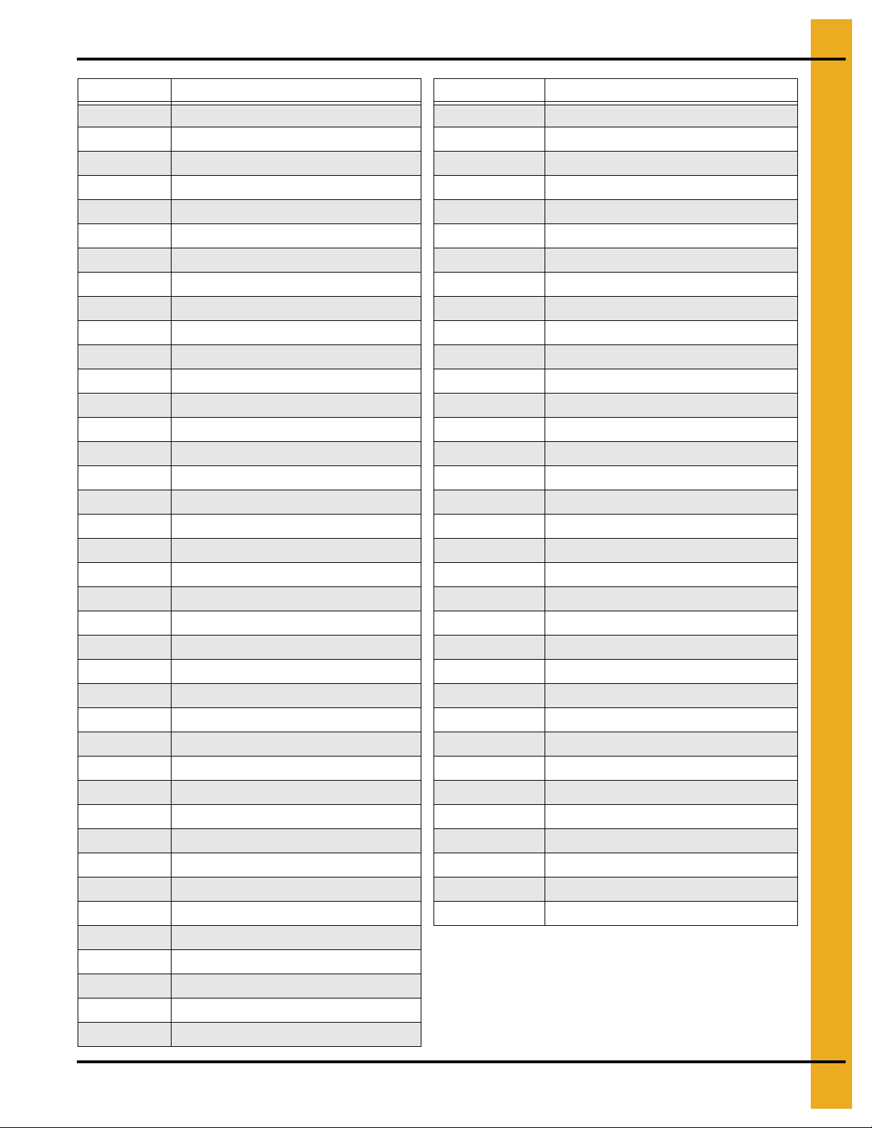
11. Miscellaneous Parts by Description
Part # Description Part # Description
HF-7200 250° Bin High-Limit Assembly HF-7719 Downwind Heater Box - CNC OPS
HF-7431 Access Panel Assembly Dow nwind Heater HF-7653 Downwind Housing Bottom: 10-15
HF-7287 Access Panel Bracket - Do wnwind Heaters HF-7781 Downwind Housing Bottom: 20-30
HF-7288 Access Panel Do wnwind Heater HF-7803 Downwind Housing Bottom: 40
D03-0099 Adapter Tab 0.187" x 0.187" HF-7662 Downwind Housing Profile Bottom: 10-15
HF-7698 Backing Plate - Heater Controls HF-7786 Downwind Housing Profile Bottom: 20-30
D63-0006 Block, Contact N.O. HF-7805 Downwind Housing Profile Bottom: 40
S-6606 Flange Bolt 5/16"-18 x 3/4" ZN Grade 5 HF-7661 Downwind Housing Profile Top: 10-15
S-1 101 Bolt, HHCS 1/4"-20 x 1/2" ZN Grade 2 HF-7785 Downwind Housing Profile Top: 20-30
756-1485-9 Boot - For Flame Rod and Igniter-A HF-7804 Downwind Housing Profile T op: 40
HF-7665 Burner Mounting Grip: Downwind Heater FH-7050 Elbow, 3/8" 90° PVC w/ Nut
415-4312-5 Burner Sub-Assembly CFDH27 HF-7655 Downwind Housing Side: L.H. 10-15
415-4434-7 Burner Sub-Assembly CFDH30/33 D03-0696 Latch, Farm Fans Control Box
HH-1096 Clamp, 1/2" Conduit HF-7784 Downwind Housing Side: L.H. 20-30/40
HF-7710 Conduit Assembly - Downwind Flame Rod Wire HF-7654 Downwind Housing Side: R.H. 10-15
415-4222-6 Conduit Assembly - Downwind Heater to Fan HF-7783 Downwind Housing Side: L.H. 20-30/40
HF-7709 Conduit Assembly - Downwind Ignition Wire FH-7404 Fuse, 2 Amp 1/4" x 1-1/4" Slow Blow
HF-7723 Conduit Assembly - Liquid Solenoid w/ Din DW HF-7652 Downwind Housing T op: 10-15
HF-7722 Conduit Assembly - Main Solenoid w/ Din DW HF-7780 Downwind Housing Top: 20-30
FH-1310 Con nector, Cord HEYCO #3231 HF-7802 Downwind Housing Top : 40
069-1376-8 Control Box Lid - Poly Blank 025-1203-6 Plug, Hole - 7/8" Diameter Liquid Tight
HF-7694 Control Box Sub-Assembly: Downwind Deluxe THH-4071 Elbow, 1/2"-90° SCH 40 Black
HF-7796 Cover Plate - Downwind Vaporizer Hole HH-4847 Elbow, 1/2"-90° SCH 80 Black
DC-889 Decal, Danger High Voltage THH-4153 Elbow, 1" x 1/2" - 90° Reducing SCH 40
420-1422-5 Decal, 115 Volt 1 Phase FH-1309 Lock Nut 1/2" with Pipe Threads
DC-113 Decal, Air Flow THH-4149 Elbow, 3/4"-1/2" Reduce SCH 40
DC-1224 Decal, Danger High Voltage (LG) 90-0009 Lamp, Oil Tight 1/4" TAB 120V
DC-1254 Decal, Ground Lug 24 Per Sheet E160-1137 Lug Ground, #TA-2 (CSA)
DC-108 Decal, High-Limit Button THH-4179 Flame Sensor 6" Long Rod
DC-1718 Decal, Warning Heater Fire S-2052 Foam Strip 1/8" Thread x 1/2" Wide
DC-1559 Decal, Warning: DC-1225/DC-1227 025-1202-8 Gasket - Adapter Plate/Motor C
DC-1170 Decal, Deluxe Heater Wiring HH-2984 Gauge, Pre s sure 0-30# LP
DC-1702 Decal: Caution Use TSTAT w/ Heater HF-7379 Heater Cover Plate 1996<
FH-7038 Fitting, Sealtite PVC 3/8" HF-7509 Hose, 1/2" x 18" LP Gas Assembly
DC-1695 Decal, Heater Plastic Control Box Deluxe D07-0009 Hose, 3/8" x 24" LG LP Gas 350 Max
HF-7318-1 Deluxe Circuit Board HH-7014 Jumper J6-2 Terminal Strip
FH-7049 Ada pter, Connector PVC 3/8" Straight w/ Nut PNEG-588-04 Ma nual, Heater Deluxe Downwind 04
006-1354-7 Din Connector - 1/2" NPT 090-1705-4 Screw, MS #8-32 x 3/8" Phillip s PHSEMS
HH-7046 Crimp, Disconnect 0.187" Female 007-1110-1 Nipple, 1" x 7"
46 PNEG-588-04 Deluxe Downwind Heater Installation and Operation
Page 47
11. Miscellaneous Parts by Description
Part # Description Part # Description
090-1701-3 Screw, MS #10-24 x 1/2" PHS ZN S-7192 Screw, MS #8-32 x 5/8" PHP ZN
THH-4117 Nipple, 1" Close SCH 40 Black D03-0247 Wire Tie 5" Panduit #PLT 1.5M-M
THH-4059 Nipple, 1" x 5-1/2" SCH 40 Black WR-18GRN/YLW Wire, 18 Gauge Green/Yellow Stranded
THH-4032 Nipple, 1/2" Close SCH 40 Black 07098556 Shroud 16" Motor Cord
090-1699-9 Rivet, Pop 1/8" Diameter x 0.775" Long CH-6873 Silicone Cartridge Clear RTV
THH-4088 Nipple, 1/2" x 4" SCH 40 Black WR-18BLU Wire, 18 Gauge Blue Stranded
THH-4121 Nipple, 3/4" Close SCH 40 Black WR-18FPGR Wire, 18 Gauge GR Teflon Flame SNS
HH-7098 Nipple, 3/4" x 12" SCH 40 Black WR-18GRN/YLW Wire, 18 Gauge Green/Yellow Stranded
D08-0020 Nipple, 3/4" x 6" SCH 40 Black WR-18FPRD Wire, 18 Gauge RD Teflon Flame SNS
S-7215 Flange Nut 1/4"-20 ZINC WR-7MM Wire, 7 MM Silicone Ignitor
S-280 Screw, SDS #10-16 x 5/8" HWH ZN E105-1102 Wire Kit - VA/DW Heaters Deluxe
S-968 Flange Nut 3/8"-16 ZN Grade 5 D02-0039 Wire Tie Anchors
S-2786 Screw, TCSF #8-32 x 3/8" RHP ZN E305-0282 WR 126" (18 Black) 1/4 Spade/3/8"
S-3611 Flan ge Nut 5/1 6-18 ZN YDP HH-1650 Spark Plug Auburn #I-31
S-8927 Jam Nut M14 x 1-1/4" Black HH-1251 Strainer, 1/2" Y 250# WOG SCH 80
07098556 Shroud 16" Motor Cord DC-1461 Decal, Tag Attention Pre ssure Gauges
HF-7794 Orifice Holder- Quad Heater - 3/4" HH-1092 Switch, High-Limit 180°
HF-7749 Orifice Plug (3/4) Drill: 17/64" HH-7013 Switch, Screw-In Vapor High-Limit
006-1363-8 Sealing Washer 0.85 I.D. Black 707-1175-9 Union, 3/4" SCH 40 Black
HF-7708 Orifice Plug (3/4) Drill: 21/64" 007-1106-9 Tee, 1" x 1" x 3/4"
HF-7750 Orifice Plug (3/4) Drill: 25/64" THH-4137 Tee, 1" x 1" x 1" NPT SCH 40 Black
HF-7809 Orifice Plug (3/4) Drill: 5/16" THH-4058 Tee, 1/2" x 1/2" x 1/2" SCH 80 Black
HH-1 1 06 Terminal, 3/16" Eyelet HH-1487 Transformer Single Pole 120V
HF-7211 Snap Track 4" x 6" (Ciruit Board) HF-7705 Piping Sub-Assembly 1.0 (CHD-30)
HF-7810 Orifice Plug (3/4) Drill: 7/16" HF-7808 Piping Sub-Assembly 1.0 (CHD-40)
S-4764 Spade Terminal MV14-6FBX Fork HF-77 04 Pipin g Sub-Assembly 3/4 (CHD-15)
HF-7701 Orifice Plug (3/4) Drill: 7/32" 056-2224-6 Solenoid Valve 1" NPT 115V Din
S-7598 Paint, Black Spray 056-2223-8 Solenoid Valve 3/4" NPT 115V Din
HF-7696 Switch 2 Position Selector: Lever 410-1783-1 Vaporizer Adjusting Weldment
007-1747-0 Plug, Pipe 1/4" CD-0197 Vaporizor Coil for Downwind Heaters
HF-7686 Pipe Train Assembly: LP Supply DW 04 S-3674 Flat Washer #10 SAE ZN
HF-7575 Pipe Train Bracket: Downwind Unipipe HF-7380 Window Access 0.060 x 6 x 6 Plastic
HF-1026 Pipe Train Bracket: Vane Axial Heaters WR-18BRN Wire 18 Gauge Brown Stranded
WR-18WHT Wire 18 Gauge White Stranded WR-18YLW Wire 18 Gauge Yellow Stranded
HF-7795 Pivot Bracket: Downwind Vaporizer 04
045-1068-1 Terminal Strip Assembly 20A 2 Position W
THH-4001 Reducer, 1" x 1/4" Hex Bushing S40 BL
TFC-0023-50 Regulator, 1/2" NPT - CSA 50 PSI
090-1709-6 Retainer Nut 5/16"-18 x 0.120" ZN
PNEG-588-04 Deluxe Downwind Heater Installation and Operation 47
Page 48

NOTES
48 PNEG-588-04 Deluxe Downwind Heater Installation and Operation
Page 49

12. Warranty
9101239_1_CR_rev7.DOC (revised July 2009)
GSI Group, LLC Limited Warranty
The GSI Group, LLC (“GSI”) warrants products which it manufactures to be free of defects in materials and workmanship
under normal usage and conditions for a period of 12 months after sale to the original end-user or if a foreign sale,
14 months from arrival at port of discharge, whichever is earlier. The end-user’s sole remedy (and GSI’s only obligation)
is to repair or replace, at GSI’s option and expense, products that in GSI’s judgment, contain a material defect in materials
or workmanship. Expenses incurred by or on behalf of the end-user without prior written authorization from the GSI
Warranty Group shall be the sole responsibility of the end-user.
Warranty Extensions:
The Limited Warranty period is extended for the following products:
Product Warranty Period
Performer Series Direct Drive Fan Motor 3 Years
AP Fans and Flooring
Cumberland
Feeding/Watering
Systems
Grain Systems Grain Bin Structural Design 5 Years
Grain Systems
Farm Fans
Zimmerman
All Fiberglass Housings Lifetime
All Fiberglass Propellers Lifetime
Feeder System Pan Assemblies 5 Years **
Feed Tubes (1-3/4" and 2.00") 10 Years *
Centerless Augers 10 Years *
Watering Nipples 10 Years *
Portable and Tower Dryers 2 Years
Portable and Tower Dryer Frames and
Internal Infrastructure †
5 Years
* Warranty prorated from list price:
0 to 3 years - no cost to end-user
3 to 5 years - end-user pays 25%
5 to 7 years - end-user pays 50%
7 to 10 years - end-user pays 75%
** Warranty prorated from list price:
0 to 3 years - no cost to end-user
3 to 5 years - end-user pays 50%
† Motors, burner components
and moving parts not included.
Portable dryer screens included.
Tower dryer screens not included.
GSI further warrants that the portable and tower dryer frame and basket, excluding all auger and auger drive components,
shall be free from defects in materials for a period of time beginning on the twelfth (12
and continuing until the sixtieth (60
th
) month from the date of purchase (extended warranty period). During the extended
th
) month from the date of purchase
warranty period, GSI will replace the frame or basket components that prove to be defective under normal conditions of
use without charge, excluding the labor, transportation, and/or shipping costs incurred in the performance of this
extended warranty.
Conditions and Limitations:
THERE ARE NO WARRANTIES THAT EXTEND BEYOND THE LIMITED WARRANTY DESCRIPTION SET FORTH
ABOVE. SPECIFICALLY, GSI MAKES NO FURTHER WARRANTY OF ANY KIND, EXPRESS OR IMPLIED,
INCLUDING, WITHOUT LIMITATION, WARRANTIES OF MERCHANTABILITY OR FITNESS FOR A PARTICULAR
PURPOSE OR USE IN CONNECTION WITH: (I) PRODUCT MANUFACTURED OR SOLD BY GSI OR (II) ANY ADVICE,
INSTRUCTION, RECOMMENDATION OR SUGGESTION PROVIDED BY AN AGENT, REPRESENTA TIVE OR
EMPLOYEE OF GSI REGARDING OR RELATED TO THE CONFIGURATION, INSTALLATION, LAYOUT, SUITABILITY
FOR A PARTICULAR PURPOSE, OR DESIGN OF SUCH PRODUCTS.
GSI shall not be liable for any direct, indirect, incidental or consequential damages, including, without limitation, loss of
anticipated profits or benefits. The sole and exclusive remedy is set forth in the Limited Warranty, which shall not exceed
the amount paid for the product purchased. This warranty is not transferable and applies only to the original end-user. GSI
shall have no obligation or responsibility for any representations or warranties made by or on behalf of any dealer, agent
or distributor.
GSI assumes no responsibility for claims resulting from construction defects or unauthorized modifications to products
which it manufactured. Modifications to products not specifically delineated in the manual accompanying the equipment at
initial sale will void the Limited Warranty.
This Limited Warranty shall not extend to products or parts which have been damaged by negligent use, misuse, alteration,
accident or which have been improperly/inadequately maintained. This Limited Warranty extends solely to products
manufactured by GSI.
Prior to installation, the end-user has the responsibility to comply with federal, state and local codes which apply to the
location and installation of products manufactured or sold by GSI.
PNEG-588-04 Deluxe Downwind Heater Installation and Operation 49
Page 50

This equipment shall be installed in accordance with
the current installation codes and applicable
regulations, which should be carefully followed in all
cases. Authorities having jurisdiction should be
consulted before installations are made.
Copyright © 2013 by GSI Group
Printed in the USA
GSI Group
1004 E. Illinois St.
Assumption, IL 62510-0020
Phone: 1-217-226-4421
Fax: 1-217-226-4420
www.gsiag.com
CN-302062
 Loading...