

Page 1
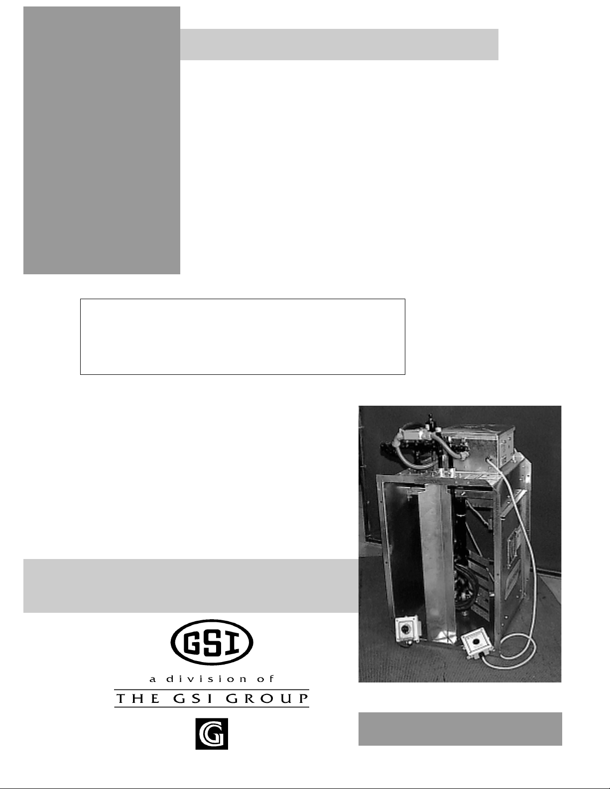
Deluxe Centrifugal Heater
Deluxe Downwind
Centrifugal Heater
Installation And
Operating Instructions
MODEL # CH - __ __ - __ __ - D (HIGH)
MODEL # CL - __ __ - __ __ - D (LOW)
Owner's
Manual
MANUAL # PNEG-588
1
Page 2

CHECK LIST
_____ 1. All wire connections
_____ 2. Spark plug gap - .125
_____ 3. Pipetrain tightness and gas leaks
_____ 4. Flame sensor tight
_____ 5. Fuse in place, extra fuse provided
_____ 6. Flame out light
_____ 7. Indicator light
_____ 8. Pressure gauge
_____ 9. Regulator adjusted
_____ 10. Shut off valve operates correctly
_____ 11. Vapor high limit
Deluxe Centrifugal Heater
_____ 12. Unit cycles ON to OFF
_____ 13. Heat rise even across transition
_____ 14. Unit cycles HI to LO (HI-LO only)
_____ 15. Mod valve holds temp within 1 degree (mod units only)
_____ 16. All decals and serial number tag
_____ 17. Aesthetic appearance
_____ 18. Manual
Tester Signature___________________________________________
Date____________________________________
2
Page 3

Deluxe Centrifugal Heater
Roof Damage Warning and Disclaimer.............................................................................4
Safety Alert Decals.......................................................................................................5
Centrifugal Heater Installation......................................................................................6
Fuel Connection.....................................................................................................6
Heater Electrical Installation (230V Fans).............................................................7
Heater Electrical Installation (460V Fans)..............................................................8
Plenum Thermostat Mounting...............................................................................9
Transition Hi-Limit Installation................................................................................9
Bin Configuration and Operating Temperature Table..............................................10
Second Heater Installation....................................................................11
Temperature Heater Specifications......................................................................12
Heater Dimensional Specifications.......................................................................12
Centrifugal Heater Operating Procedure..........................................................................13
T ABLE OF CONTENTS
Standard Heater Operation..................................................................................13
Hi-Lo Heater Operation.........................................................................................13
Modulating Valve Operation....................................................................................14
BTU's Per Gauge Pressure (PSI) Propane Models (Approximate)......................15
BTU's Per Gauge Pressure (PSI) Natural Gas Models (Approximate).................16
Adjusting The Vaporizor........................................................................................17
Centrifugal Heater Wiring Diagram.............................................................................18
10-15 DW High Temp Heater Parts.........................................................................19
10-15 DW Low Temp Heater Parts...................................................................................20
20-30 DW High Temp Heater Parts....................................................................21
20-30 DW Low Temp Heater Parts.............................................................22
40HP DW High Temp Heater Parts........................................................................23
40HP DW Low Temp Heater Parts.........................................................................24
DW Gas Heater Control Box Parts..........................................................................25
DW Propane Vapor Pipetrain Parts............................................................................26
DW Natural Gas Vapor Pipetrain Parts.............................................................................27
DW Propane Vapor Hi-Lo Pipetrain Parts.................................................................28
DW Natural Vapor Hi-Lo Pipetrain Parts.........................................................................29
DW LP Pipetrain Parts...........................................................................30
Notes...........................................................................................................................31
Warranty...............................................................................................32
3
Page 4
SAFETY
Deluxe Centrifugal Heater
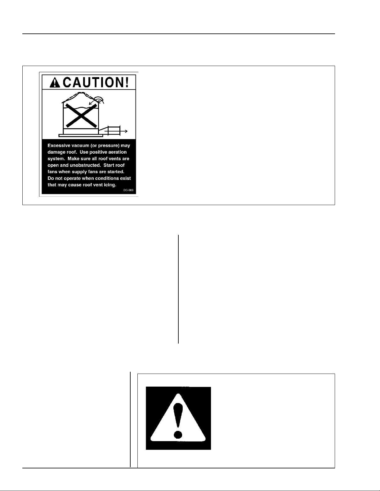
Roof Damage Warning And Disclaimer
GSI DOES NOT WARRANT ANY ROOF DAMAGE CAUSED
BY EXCESSIVE VACUUM OR INTERNAL PRESSURE FROM
FANS OR OTHER AIR MOVING SYSTEMS. ADEQUATE VEN-
TILATION AND/OR "MAKEUP AIR" DEVICES SHOULD BE
PROVIDED FOR ALL POWERED AIR HANDLING SYSTEMS.
GSI DOES NOT RECOMMEND THE USE OF DOWNWARD
FLOW SYSTEMS (SUCTION). SEVERE ROOF DAMAGE CAN
RESULT FROM ANY BLOCKAGE OF AIR PASSAGES. RUN-
NING FANS DURING HIGH HUMIDITY/COLD WEATHER
CONDITIONS CAN CAUSE AIR EXHAUST OR INTAKE PORTS
TO FREEZE.
Heater Operation
Thank you for choosing a GSI product. It is de-
signed to give excellent performance and service
for many years.
This manual describes the operation of the De-
luxe Downwind Centrifugal Heater. It is designed for
low to medium temperature grain conditioning, and is
ideal for the aeration of rice, popcorn or other select
grains. It is available in both propane vapor and natural
gas models.
The principal concern of GSI is your safety and
the safety of others associated with grain handling
Safety Alert Symbol
The symbol shown is used to call
your attention to instructions con-
cerning your personal safety. Watch
for this symbol; it points out impor-
tant safety precautions. It means
"ATTENTION", "WARNING",
"CAUTION", and "DANGER".
Read the message and be cautious
to the possibility of personal injury
or death.
equipment. This manual is written to help you un-
derstand safe operating procedures, and some of the
problems that may be encountered by the operator
or other personnel.
As owner and/or operator, it is your responsi-
bility to know what requirements, hazards and pre-
cautions exist, and to inform all personnel associ-
ated with the equipment, or who are in the area.
Avoid any alterations to the equipment. Such alter-
ations may produce a very dangerous situation,
where serious injury or death may occur.
WARNING! BE ALERT!
Personnel operating or working around
electric fans should read this manual.
This manual must be delivered with the
equipment to its owner. Failure to read
this manual and its safety instructions is
a misuse of the equipment.
4
Page 5
Deluxe Centrifugal Heater
The GSI Group Inc. recommends con-
tacting your local power company, and hav-
ing a representative survey your installation
so the wiring is compatible with their sys-
tem, and adequate power is supplied to your
unit.
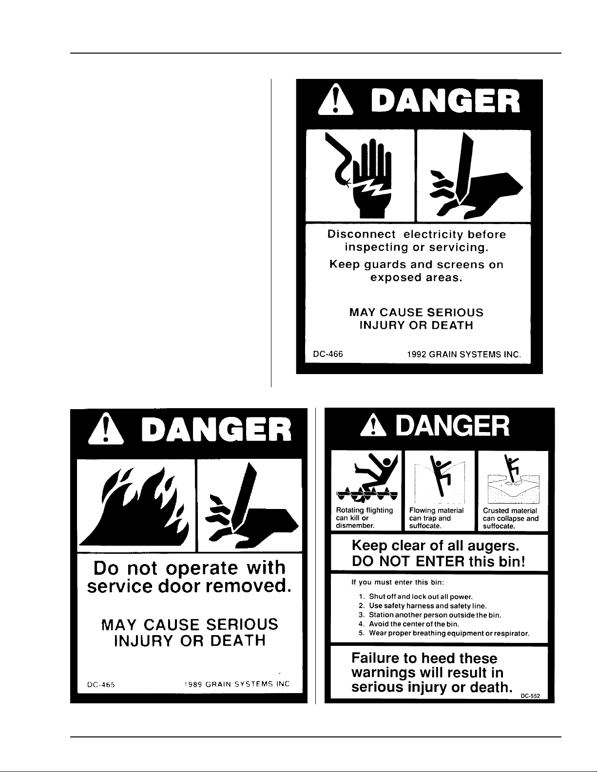
Safety decals should be read and un-
derstood by all people in the grain han-
dling area. The bottom right decal should
be present on the inside bin door cover of
the two ring door, 24" porthole door cover
and the roof manway cover.
If a decal is damaged or is missing
contact:
The GSI Group Inc.
1004 E. Illinois St.
Assumption, IL 62510
217-226-4421
A free replacement will be sent to you.
SAFETY ALERT DECALS
5
Page 6
INSTALLATION
Liquid Propane Models
Deluxe Centrifugal Heater
Fuel Connection
Important! Do not use propane tanks which have previously
been used for ammonia unless they have been purged accord-
ing to procedures of the National L. P. Association.
Be sure fuel supply system complies with all local codes
for L. P. gas installations.
1. LP models are designed to run on liquid pro
pane, with liquid draw from the propane tank.
Avoid using propane supply tanks that have
been used for vapor draw for long periods of
time. When using liquid draw systems any mois-
ture that may be present in tank or lines may
freeze when system is used in cold weather. To
avoid this, the usual precaution is to purge the
system with methanol.
2. Run proper size line (see specifications) to liq-
uid pipetrain on heater. Have a qualified gas
service man inspect installation to be sure that
everything is installed according to local codes
and ordinances.
3. After installation is complete check all connec-
tions for leaks with liquid detergent or compa-
rable. Wear rubber gloves and eye protection.
Avoid contact with liquid propane. DO NOT USE
FLAME FOR LEAK TESTING.
Propane Vapor Models
2. Run proper size line (see specifications) to pipe-
train on heater. Have a qualified gas service
person inspect installation to be sure everything
is installed according to local codes and ordi-
nances.
3. After installation is complete check all connec-
tions for leaks.
DO NOT USE FLAME FOR LEAK TESTING.
(See above for other precautions.)
Natural Gas Models
1. Natural gas models are similar to vapor models,
but have a larger orifice to accommodate
lower pressure sometimes found with natural
gas.
2. Run proper size line (see specifications) to pipe-
train on heater. Have a qualified gas service
man inspect installation to be sure everything is
installed according to local codes and ordi-
nances.
1. Propane vapor models are designed to run di-
rectly off of supply tank or from a separate ex-
ternal vaporizer.
6
3. After installation is complete check all connec-
tions for leaks. DO NOT USE FLAME FOR
LEAK TESTING. (See above for other precau-
tions.)
Page 7
Deluxe Centrifugal Heater
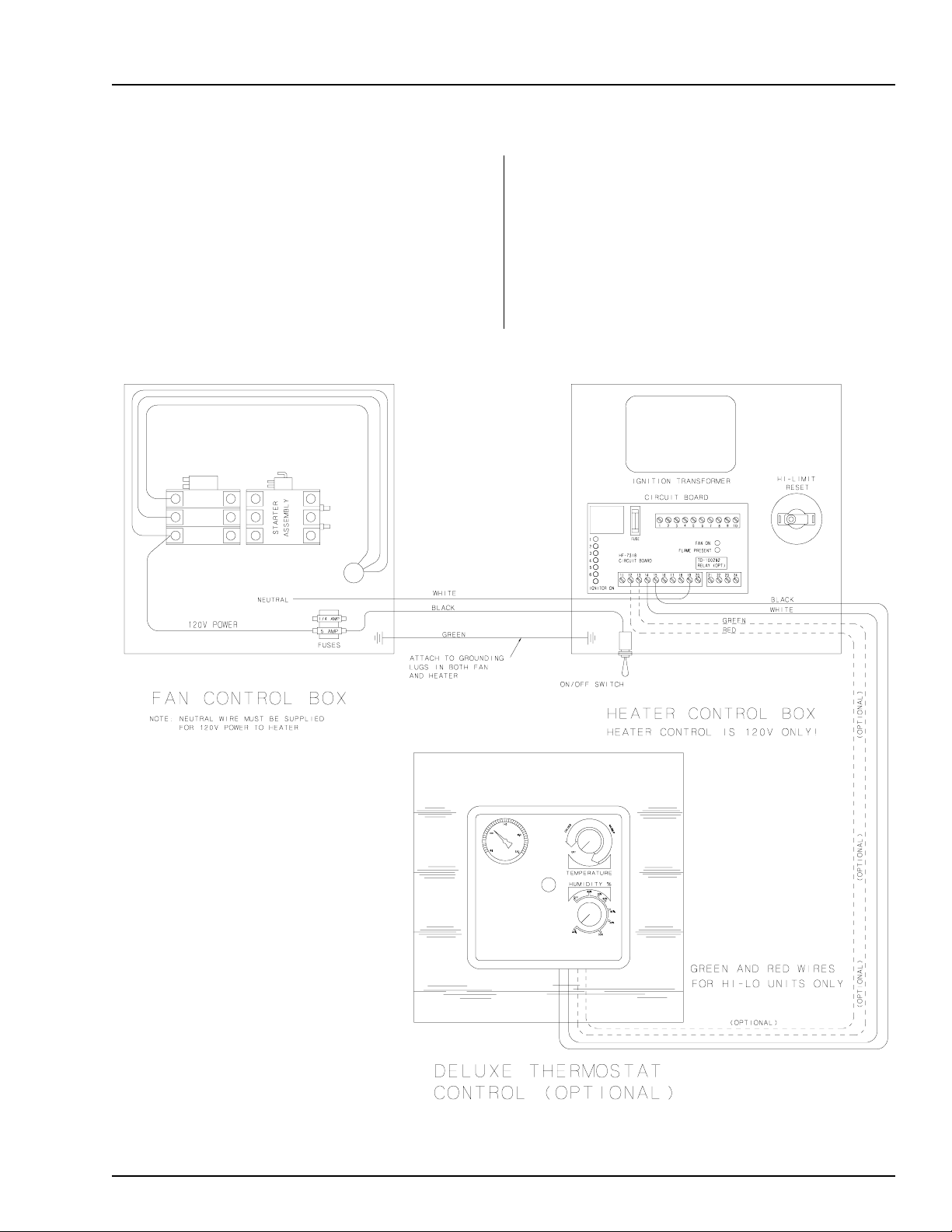
Electrical Installation (230v Fans)
INSTALLATION
1. Connect power cord to fan control box.
2. Make field connections of wires in fan box as
shown in Figure 1.
3. Connect deluxe thermostat control ( optional)
in heater box as shown in Figure 1.
IMPORTANT! HEATER MUST BE INTER-
LOCKED WITH FAN FOR SAFE OPERATION.
IMPORTANT! THERMOSTAT MUST
BE INSTALLED FOR SAFE OPERATION.
Figure 1: 230 volt fan control box.
7
Page 8
INSTALLATION
Deluxe Centrifugal Heater
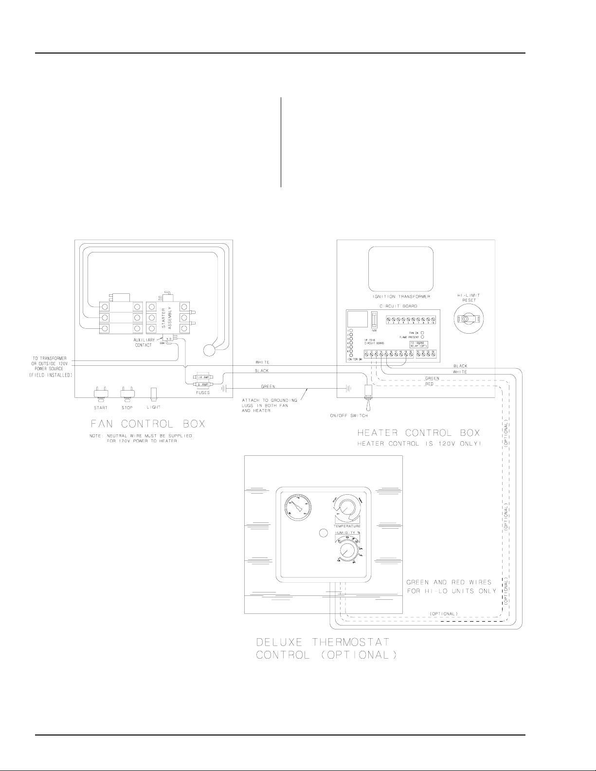
Electrical Installation (460v Fans)
1. Connect power cord to fan control box.
2. Make field connections of wires in fan box
as shown in Figure 2. 110V power supply
or .5KVA 460V to 110V transformer must be
used to supply power for heater.
IMPORTANT! HEATER MUST BE INTER-
LOCKED WITH FAN FOR SAFE OPERATION.
3. Connect deluxe thermostat control (optional) as
shown in Figure 2. IMPORTANT! THERMO-
STAT MUST BE INSTALLED FOR SAFE
OPERATION.
Figure 2: 460 volt fan control box.
8
Page 9
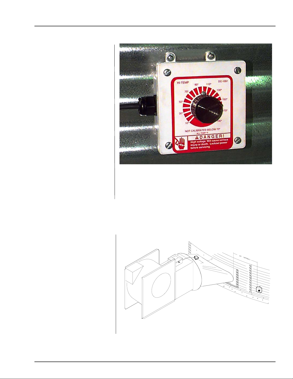
Deluxe Centrifugal Heater
Plenum Thermostat
Mounting
The plenum thermostat is the 4 x 4
white box with knob that is
preconnected to heater when heater
is ordered with thermostat.
1. 24" to the right side of the transi-
tion, drill one
temp) or 1
in the center of the plenum in a
valley (4.00" corrugation) or hill
(2.66" corrugation) on bin
sidewall.
3
/8" hole (high
1
/2" hole (low temp)
INSTALLATION
2. Insert the probe through the hole.
3. Position the housing so that the
tabs are vertical, and the cord
exits the housing horizontally.
1. Mark location on transition one
(1) foot up from the bottom
(entrance collar) and centered
in the transition.
2. Drill or knock out 7/8" diameter
hole on marked location.
3. Install transition hi-limit using
supplied self drilling screws.
Plenum thermostat mounting on bin wall.
4. Use 4 self drilling screws to mount the housing to the bin sidewall.
5. Caulk between the housing and the sidewall to seal.
Transition Hi-limit Installation
Figure 3: The transition connecting the heater to the bin with the plenum
thermostat in place.
9
Page 10
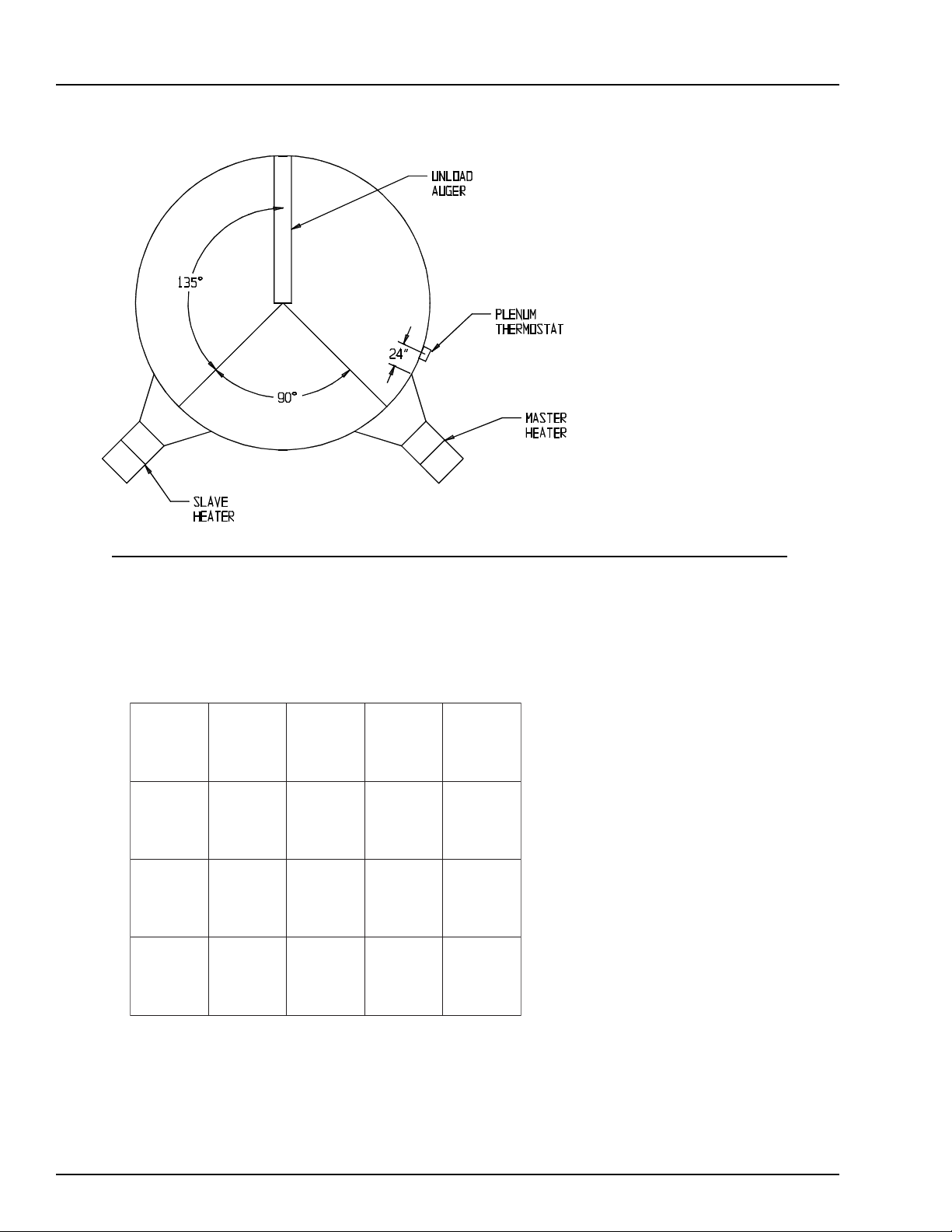
BIN CONFIGURATION
Deluxe Centrifugal Heater
IMPORTANT!
When mounting (2)
heaters on a bin it is
imperative that they
be situated as in above
drawing. Plenum
thermostat must be to
the right of master
heater and master
heater must be to the
right of slave heater.
Operating Temperature Table
PMET-OL
HCTAB
0
02-5
NROC
ECIR
SNAEB
&
TAEHW
EVOBA
TNEIBMA
PMET
0
01-5
EVOBA
TNEIBMA
PMET
0
02-5
EVOBA
TNEIBMA
PMET
-HGIH
PMET
YRDHCTAB
GNIRRITSON
0
021
0
001
0
011
THIS TABLE IS NOT INTENDED AS A DRYING GUIDE.
IT SHOULD BE USED AS A REFERENCE FOR SETTING MAXIMUM PLENUM
TEMPERATURE FOR SAFE OPERATION.
-HGIH
PMET
HTIW
GNIRRITS
0
041
SUOUNITNOC
WOLF
)GNITALUCRICER(
0
061
IMPORTANT!
DO NOT EXCEED
PLENUM
TEMPERATURES
0
001
0
021
TON
DEDNEMMOCER
TON
DEDNEMMOCER
LISTED IN TABLE
10
Page 11

Deluxe Centrifugal Heater
SECOND HEATER INSTALLATION
For Units Using
HF-7318 Control Board
2 Deluxe heaters may be connected to one grain
drying system and wired so they cycle together.
One of the heaters should have a thermostat
connected to it as per the installation instructions.
That heater will be referred to as the master. The
other heater (without the thermostat) will be
referred to as the slave.
Installation For
Standard Units
1. Install relay base (TD-100283) in master
heater control box.
2. Connect wire between term 6 on circuit board
and terminals 14 on relay base in master
heater.
3. Connect wire between term 13 on relay base
and terminals 8 on circuit board in master
heater.
4. Run 2 wires (18 gage) between master and
slave heaters.
5. Connect wires to terminal 5 and 9 (points A
and B) on relay base in master heater.
6. Connect wire from terminal 9 in master to
terminal 14 (point F) in slave unit.
7. Connect wire from terminal 5 in master to
terminal 15 (point E) in slave unit.
8. Install relay (TD-100282) in relay base.
Additional Steps For
Hi-Lo Units
1. Run 2 wires (18 gage) between master and slave
unit.
2. Connect wires to terminals 21 and 22 (points C
and D) on circuit board in main heater.
3. Connect wire from terminal 21 in master to
terminal 12 (point H) in slave unit.
4. Connect wire from terminal 22 in master to
terminal 13 (point G) in slave unit.
5. Install relay (TD-100282) in relay base.
Figure 4: The HF-7318 control board.
11
Page 12

INSTALLATION
Deluxe Centrifugal Heater
Centrifugal Heater Specifications
All models
Liquid models
Vapor models
Natural gas
models
BTU rating
Weight
Maximum fuel flow (GPH)
Orifice size
Minimum operating pressure
Maximum operating pressure
Minimum line size
Maximum fuel flow (CFH)
Orifice size
Minimum operating pressure
Maximum operating pressure
Minimum line size
Maximum fuel flow (CFH)
Orifice size
Minimum operating pressure
Maximum operating pressure
Minimum line size
Heater Dimensional Specifications
Hi-Temp Model
4000000
145
43
.25
3
30
3/8"
1590
.25
2
30
1"
4200
.375
1
15
1.1/4"
Lo-Temp Model
500000
135
N/A
N/A
N/A
N/A
N/A
210
.109
1
15
1/2"
500
.156
1
7
1"
Heater Size
Inside Height
Inside Width
Inside length
10-15
30.1/4"
19.1/2"
24"
20-30
33.1/4"
21.3/4"
24"
40
33.1/4"
23.11/16"
24"
12
Page 13

Deluxe Centrifugal Heater
Standard Heater Operation
OPERATING PROCEDURE
1. Thermostat must be wired into heater con-
trol box for heater to operate.
2. Open all manual shut-off valves to heater unit.
3. Start fan. This will supply power to heater.
4. Turn thermostat dial to its highest setting.
5. Turn toggle switch on.
6. Heater should now be lit. If not check to see
that all gas is on.
7. Set thermostat to desired setting (see de-
luxe thermostat manual for adjusting deluxe
thermostat control).
8. Gas pressure should be adjusted so burner
is on 75 per cent of the time.
9. Watch as burner goes through a few cycles,
to be sure that it is operating properly.
Hi-lo Heater Operation
3. Start fan. This will supply power to heater.
4. Turn thermostat dial to its highest setting.
5. Turn toggle switch on.
6. After 20 seconds both red lights should light up
indicating power to the control circuit.
7. Heater should now be lit. If not, check to see
that all gas is on.
8. Open low-fire ball valve all the way.
9. Turn thermostat dial back slowly until heater
cycles to low flame.
10. Adjust ball valve so that low flame pressure is
at desired setting.
11. Turn thermostat dial to desired editing and wait
for bin plenum to come up to temperature.
Heater should cycle to low flame after a few
minutes. If heater does not cycle to low flame
increase hi-flame gas pressure.
1. Thermostat must be wired into heater control
box for heater to operate.
2. Open all manual shut-off valves to heater unit.
12. Low-flame should be adjusted so that tempera-
ture drops slowly until burner goes back to
high flame.
13. Watch as burner goes through a few cycles, to
be sure that it is operating properly.
13
Page 14

OPERATING PROCEDURE
Modulating Valve Operation
Deluxe Centrifugal Heater
1. The modulating valve regulates gas flow through
the heater based on sensing unit in the plenum,
and maintains a constant drying air temperature.
2. The sensing bulb of the modulating valve should
be mounted through the bin wall with the side
reading "top" up. The bulb reacts to temperature. It changes the amount of gas (increase or
decrease), burning warmer or cooler depending
on the position of the valve SET POINT. If the
bulb is cooler than it was at the SET POINT, the
bulb senses the cooler temperature and opens
the valve further so more heat is applied to the
drying air. If the bulb is warmer than it was at
the SET POINT, the valve closes further and reduces the temperature until the air is at the valve
SET POINT.
3. It is important that the pressure regulator be set
high enough to allow the modulating valve to
deliver enough gas to maintain the plenum temperature necessary. The regulator is normally
factory set at 15 psi (propane units). To set the
regulator, run the heater and turn the modulating valve T-handle in. This gets full line pressure to the burner. Then adjust regulator to read
15 psi (depending on the plenum temperature
needed).
4. Turn the fan and heater on. To set the modulating valve, turn the T-handle out (counterclockwise)
until loose and wait a few minutes for the plenum temperature to equalize. When the temperature under the bin has equalized, gradually turn
T-handle in (clockwise) about 1/2 turn at a time.
Wait until temperature under bin has equalized as
before. If temperature under bin is less than the
desired temperature, continue turning T-handle
in, increasing gas flow and waiting for plenumtemperature to equalize until the desired temperature is the stable temperature of the ple
num. If temperature under bin is the same 10
minutes after you last made any adjustments
to the T-handle you can be certain that the
temperature under the bin is the SET POINT
of the valve. 1 turn of the T-handle equals
approximately 7 degrees F of temperature.
5. The valve will now keep the plenum temperature at the set point regardless of ambient
conditions as long as humidistat or thermostat
do not shut down the heater. A bypass orifice
is used to maintain a small flame when outside temperature is near or above the set point
of the valve. The bypass insures steady application of heat at minimum gas flow operation.
Bypass orifice will only operate correctly if
pressure regulator is set correctly.
6. To observe how the modulating valve increases
the efficiency of bin drying, check the gas pressure of the unit in the morning and compare to
the pressure read mid-afternoon. If the ambient (outside) temperature is significantly
greater later in the day (as normal), the gas pressure will be less. Since less heat is required to
maintain the same temperature in the plenum,
the modulating valve will have reduced the
amount of gas used by the heater.
14
Page 15

Deluxe Centrifugal Heater
Btu's Per Gauge Pressure (Psi) Propane Models (Approximate)
OPERATING PROCEDURE
High Temperature
Operating Pressure (PSI)
All
Models
Gauge Pressure (Psi) Required To Maintain Temperature (Approximate)
Fan Model
10HP
15HP
20HP
25HP
30HP
40HP
2
1064880
Models
Static
Pressure
2"
4"
6"
2"
4"
6"
2"
4"
6"
2"
4"
6"
2"
4"
6"
2"
4"
6"
4
15028006184261082129770102383430142811780183180300223510530263828320304123130
Low Temperature
Operating Pressure (PSI)
2
All
203405428716063517708409200104570601249774014555180
(High Temp Units Only)
Heat Rise Degrees F
60
80
1
1
1
2
2
1
3
3
2
4
4
3
5
5
4
8
7
6
2
2
1
4
3
2
5
4
4
8
6
5
9
8
6
14
12
10
100
4
3
2
6
4
3
8
7
7
12
10
8
14
12
10
20
19
16
120
5
4
3
8
6
4
11
9
8
17
14
11
21
18
14
29
26
22
140
7
6
4
10
8
6
15
13
11
22
19
15
28
23
19
30
160
8
8
5
13
10
8
20
17
14
28
24
20
30
24
180
10
9
6
17
13
9
24
21
18
30
24
30
15
Page 16

OPERATING PROCEDURE
Btu's Per Gauge Pressure (Psi) Natural Gas Models (Approximate)
High Temperature
Deluxe Centrifugal Heater
Operating Pressure (PSI)
All
Models
All
Models
Gauge Pressure (Psi) Required To Maintain Temperature (Approximate)
Fan Model
10HP
15HP
20HP
25HP
30HP
40HP
2
1590000
1
195000
Static
Pressure
2"
4"
6"
2"
4"
6"
2"
4"
6"
2"
4"
6"
2"
4"
6"
2"
4"
6"
2375000
276000
60
1
1
.75
1
1
1
1.75
1.25
1
2
2
1.75
2.5
2
2
3
2.75
2.5
4
6
2749000
8
3180000
10
3555000
12
3886000
14
4195000
Low Temperature
Operating Pressure (PSI)
2
3
338000
4
390000
5
436000
6
478000
7
500000
(High Temp Units Only)
Heat Rise Degrees F
80
1.5
1.5
1.25
1.75
1.5
1.25
2.5
2
1.75
3.25
3
2.5
4
3.5
3
6
5
4
100
2
1.75
1.5
2.5
2
1.5
3.5
3
2.5
5
4
3.5
6.5
5
4
10
8
6.5
120
2.5
2
1.75
3.25
2.5
1.75
5
4
3.25
7.5
6
5
9
8
6
14
11
9
140
3
2.5
2
4
3.25
2.25
7
5
4
10
8.5
7
13
11
8.5
15
13
160
3.5
3
2.25
5
4
3
9.5
7
5
13
11
9.5
14
11
180
4
3.5
2.5
7
5.5
3.75
12
9
7
14
12
14
16
Page 17

Deluxe Centrifugal Heater
OPERATING PROCEDURE
Adjusting The Vaporizor
1. Vaporizer should be adjusted so
the vapor pipe train runs warm
to the touch (100°-120°F).
2. Loosen 5/16" bolts on adjust-
ment bracket.
3. Raise vaporizer if running too
hot, lower if too cold.
4. Move vaporizer only 1" at a time
and allow a few minutes for tem-
perature to equalize.
5. Tighten 5/16" bolts and watch
heater run for several minutes
to verify adjustment.
Adjusting the vaporizer coil on a liquid propane model.
The top photo shows the setting up (cool),
and the bottom photo shows the coil down (hot).
17
Page 18

WIRING DIAGRAM
Deluxe Centrifugal Heater
18
Page 19

Deluxe Centrifugal Heater
10-15 Dw High Temp Heater Parts
HEA TER PARTS
1 HF-7076 10-15 HP Housing Assembly
2 HF-7288 Access Side Cover
3 HF-7380 Plastic View Window
4 HF-7379 Access Panel Cover Plate
5 HF-7287 Access Panel Holders
6 HF-7063 10-15 Diverter Plate
7 CD-0238 Ignitor (2 Required)
8 HF-7201 Ignitor Clamp Half (2 Required)
9 HF-7204 Ignitor Bracket
10 HF-7101 10-15 Diverter Angle
11 CD-0187 Flame Sensor Bracket (Deluxe, Sr 2000)
12 *THH-4179 Flame Sensor (Deluxe, Sr 2000)
13 HF-7290 10-15 Burner Brace
14 HH-7035 1 1/4" Coupling
15 HF-7083 1/4" Orifice (Propane)
15 HF-7034 3/8" Orifice (Natural Gas)
16 HF-7027 Orifice Tube Weldment
17 THH-4071 1/2" Elbow
18 HH-3854 1/2" x 6" Nipple
19 HH-3670 1/2" x 2.1/2" Nipple
20 S-7259 5/16" U-Bolt
21 HF-7079 Diverter Angle Cover
22 HF-7020 Vaporizer Support Weldment
23 HF-7297 Burner Support Plate
24 HF-7032 Vapor Cover Plate
25 HF-7023 HI-Fire Burner Assembly
NS HF-7261 10-40HP Spark Plug Wire
NS HF-7263 10-40HP Flame Probe Wire
19
Page 20

HEATER PARTS
Deluxe Centrifugal Heater
10-15 Dw Low Temp Heater Parts
1 HF-7076 10-15 HP Housing Assembly
2 HF-7288 Access Side Cover
3 HF-7380 Plastic View Window
4 HF-7379 Access Panel Cover Plate
5 HF-7287 Access Panel Holders
6 HF-7063 10-15 Diverter Plate
7 CD-0238 Ignitor (2 Required)
8 HF-7201 Ignitor Clamp Half (2 Required)
9 HF-7204 Ignitor Bracket
10 HF-7101 10-15 Diverter Angle
11 CD-0187 Flame Sensor Bracket (Deluxe, Sr 2000)
12 *THH-4179 Flame Sensor (Deluxe, Sr 2000)
13 HF-7290 10-15 Burner Brace
14 HF-7072 LO-Fire Diverter Spacer
15 HF-7071 LO-Fire Diverter
16 HF-7070 LO-Fire Burner Assembly
17 HF-7035 7/64" Orifice (Propane)
17 HF-7036 5/32" Orifice (Natural Gas)
18 HF-7069 LO-fire Orifice Weldment
19 THH-4071 1/2" Elbow
20 HH-3854 1/2" x 6" Nipple
21 HH-3670 1/2" x 2.1/2" Nipple
22 S-7259 5/16" U-Bolt
23 HF-7079 Diverter Angle Cover
24 HF-7297 Burner Support Plate
25 HF-7032 Vapor Cover Plate
NS HF-7261 10-40HP Spark Plug Wire
NS HF-7263 10-40HP Flame Probe Wire
20
Page 21

Deluxe Centrifugal Heater
20-30 Dw High Temp Heater Parts
HEATER PARTS
1 HF-7077 20-30 HP Housing Assembly
2 HF-7288 Access Side Cover
3 HF-7380 Plastic View Window
4 HF-7379 Access Panel Cover Plate
5 HF-7287 Access Panel Holders
6 HF-7064 20-30 Diverter Plate
7 CD-0238 Ignitor (2 Required)
8 HF-7201 Ignitor Clamp Half (2 Required)
9 HF-7204 Ignitor Bracket
10 HF-7102 20-30 Diverter Angle
11 CD-0187 Flame Sensor Bracket (Deluxe, Sr 2000)
12 *THH-4179 Flame Sensor (Deluxe, Sr 2000)
13 HF-7300 20-30 Burner Brace
14 HH-7035 1 1/4" Coupling
15 HF-7083 1/4" Orifice (Propane)
15 HF-7034 3/8" Orifice (Natural Gas)
16 HF-7027 Orifice Tube Weldment
17 THH-4071 1/2" Elbow
18 HH-3854 1/2" x 6" Nipple
19 HH-3670 1/2" x 2.1/2" Nipple
20 S-7259 5/16" U-Bolt
21 HF-7079 Diverter Angle Cover
22 HF-7020 Vaporizer Support Weldment
23 HF-7297 Burner Support Plate
24 HF-7032 Vapor Cover Plate
25 HF-7023 HI-Fire Burner Assembly
NS HF-7261 10-40HP Spark Plug Wire
NS HF-7263 10-40HP Flame Probe Wire
21
Page 22

HEATER PARTS
Deluxe Centrifugal Heater
20-30 Dw Low Temp Heater Parts
1 HF-7077 20-30 HP Housing Assembly
2 HF-7288 Access Side Cover
3 HH-2020 Plastic View Window
4 HF-6914 Access Cover Plate
5 HF-7287 Access Panel Holders
6 HF-7064 20-30 Diverter Plate
7 CD-0238 Ignitor (2 Required)
8 HF-7201 Ignitor Clamp Half (2 Required)
9 HF-7204 Ignitor Bracket
10 HF-7102 20-30 Diverter Angle
11 CD-0187 Flame Sensor Bracket (Deluxe, Sr 2000)
12 *THH-4179 Flame Sensor (Deluxe, Sr 2000)
13 HF-7300 20-30 Burner Brace
14 HF-7072 LO-Fire Diverter Spacer
15 HF-7071 LO-Fire Diverter
16 HF-7070 LO-Fire Burner Assembly
17 HF-7035 7/64" Orifice (Propane)
17 HF-7036 5/32" Orifice (Natural Gas)
18 HF-7069 LO-fire Orifice Weldment
19 THH-4071 1/2" Elbow
20 HH-3854 1/2" x 6" Nipple
21 HH-3670 1/2" x 2.1/2" Nipple
22 S-7259 5/16" U-Bolt
23 HF-7079 Diverter Angle Cover
24 HF-7297 Burner Support Plate
25 HF-7032 Vapor Cover Plate
NS HF-7261 10-40HP Spark Plug Wire
NS HF-7263 10-40HP Flame Probe Wire
22
Page 23

Deluxe Centrifugal Heater
40hp Dw High Temp Heater Parts
HEATER PARTS
1 HF-7472 40 HP Housing Assembly
2 HF-7288 Access Side Cover
3 HF-7380 Plastic View Window
4 HF-7379 Access Panel Cover Plate
5 HF-7287 Access Panel Holders
6 HF-7140 40 HP Diverter Plate
7 CD-0238 Ignitor (2 Required)
8 HF-7201 Ignitor Clamp Half (2 Required)
9 HF-7204 Ignitor Bracket
10 HF-7102 20-40 Diverter Angle
11 CD-0187 Flame Sensor Bracket (Deluxe, Sr 2000)
12 *THH-4179 Flame Sensor (Deluxe, Sr 2000)
13 HF-7304 40 Burner Brace
14 HH-7035 1 1/4" Coupling
15 HF-7083 1/4" Orifice (Propane)
15 HF-7034 3/8" Orifice (Natural Gas)
16 HF-7027 Orifice Tube Weldment
17 THH-4071 1/2" Elbow
18 HH-3854 1/2" x 6" Nipple
19 HH-3670 1/2" x 2.1/2" Nipple
20 S-7259 5/16" U-Bolt
21 HF-7079 Diverter Angle Cover
22 HF-7020 Vaporizer Support Weldment
23 HF-7297 Burner Support Plate
24 HF-7032 Vapor Cover Plate
25 HF-7023 HI-Fire Burner Assembly
NS HF-7261 10-40HP Spark Plug Wire
NS HF-7263 10-40HP Flame Probe Wire
23
Page 24

HEATER PARTS
Deluxe Centrifugal Heater
40hp Dw Low Temp Heater Parts
1 HF-7472 40 HP Housing Assembly
2 HF-7288 Access Side Cover
3 HH-2020 Plastic View Window
4 HF-6914 Access Cover Plate
5 HF-7287 Access Panel Holders
6 HF-7140 40 Diverter Plate
7 CD-0238 Ignitor (2 Required)
8 HF-7201 Ignitor Clamp Half (2 Required)
9 HF-7204 Ignitor Bracket
10 HF-7102 20-40 Diverter Angle
11 CD-0187 Flame Sensor Bracket (Deluxe, Sr 2000)
12 *THH-4179 Flame Sensor (Deluxe, Sr 2000)
13 HF-7304 40 Burner Brace
14 HF-7072 LO-Fire Diverter Spacer
15 HF-7071 LO-Fire Diverter
16 HF-7070 LO-Fire Burner Assembly
17 HF-7035 7/64" Orifice (Propane)
17 HF-7036 5/32" Orifice (Natural Gas)
18 HF-7069 LO-fire Orifice Weldment
19 THH-4071 1/2" Elbow
20 HH-3854 1/2" x 6" Nipple
21 HH-3670 1/2" x 2.1/2" Nipple
22 S-7259 5/16" U-Bolt
23 HF-7079 Diverter Angle Cover
24 HF-7297 Burner Support Plate
25 HF-7032 Vapor Cover Plate
NS HF-7261 10-40HP Spark Plug Wire
NS HF-7263 10-40HP Flame Probe Wire
24
Page 25

Deluxe Centrifugal Heater
Dw Gas Heater Control Box Parts
HEATER PARTS
Key Part Number Description
1 HF-7315 Control Box Housing
2 HH-7015 Snap trak
3 HF-7318 Circuit Board Assembly
4 HH-1487 Igniton Transformer
5 HH-1092 High Limit Switch 180 Degree
6 F-942 Control Box Lid
7 HH-1442 Toggle Switch
8 TFH-2021 Red Light (110V)
9 DC-1166 Decal Deluxe Heater Front Panel
10 HF-7455 High Limit Switch Box Bottom
11 FH-1310 Cord Connector
12 HF-7439 High Limit Switch 250 Degree
13 HF-7454 High Limit Switch Box Top
14 HF-7414 Recessed Plastic Plug
Revised 2/4/98
25
Page 26

HEA TER PARTS
Deluxe Centrifugal Heater
Dw Propane Vapor Pipetrain Parts
26
1 TFC-0023 1/2" 0-30 PSI Regulator (Deluxe, Sr 2000)
2 HH-3670 1/2" x 2 1/2" Nipple
3 TFC-0032 1/2" Solenoid (Deluxe, Sr. 2000)
4 HH-2029 1/2" x 1 1/2" Nipple
5 S-3853 1/2" x 1/4" x 1/2" Tee
6 HH-2984 30 PSI gauge
7 HH-2653 Modulating Valve
8 HH-1251 1/2" Strainer
9 HH-2028 1/2" Female Union
Page 27

Deluxe Centrifugal Heater
Dw Natural Gas Vapor Pipetrain Parts
HEA TER PARTS
1 TFC-0051 3/4" Ball Valve
2 THH-4136 3/4" x 3" Nipple
3 TFC-0081 3/4" Solenoid (Deluxe, Sr 2000)
4 THH-4121 3/4" Close Nipple
5 THH-4158 3/4" x 1/4" x 3/4" Tee
6 D08-0022 15 PSI Gauge
7 D67-0008 3/4" Strainer
8 HF-7230 3/4" Female Union
9 HH-7064 3/4" Modulating Valve (Optional)
27
Page 28

HEATER PARTS
Deluxe Centrifugal Heater
Dw Propane Vapor Hi-lo Pipetrain Parts
28
1 TFC-0023 1/2" 0-30 PSI Regulator (Deluxe, Sr 2000)
2 HH-3670 1/2" x 2 1/2" Nipple
3 TFC-0032 1/2" Solenoid (Deluxe, Sr 2000)
4 HH-2029 1/2" x 1 1/2" Nipple
5 HH-1453 1/2" x 1/2" x 1/2" Tee
6 THH-4067 1/2" Street Elbow
7 THH-4127 1/2" Cross
8 THH-4032 1/2" x 1/4" Reducer Bushing
9 HH-2984 30 PSI gauge
10 TFC-0030 1/2" Ball Valve
11 HH-7019 1/2" Gas Hose
12 HH-1251 1/2" Strainer
13 HH-2028 1/2" Female Union
Page 29

Deluxe Centrifugal Heater
Dw Natural Gas Hi-lo Pipetrain Parts
HEA TER PARTS
1 TFC-0051 3/4" Ball Valve
2 THH-4136 3/4" x 3" Nipple
3 TFC-0081 3/4" Solenoid (Deluxe, Sr 2000)
4 THH-4121 3/4" Close Nipple
5 THH-4174 3/4" x 3/4" x 1/2" Tee
6 THH-4066 3/4" Street Elbow
7 THH-4068 3/4" Cross
8 THH-4042 3/4" x 1/4" Reducer Bushing
9 D08-0022 15 PSI Gauge
10 D07-0028 3/4" x 1/2" Reducer Bushing
11 HH-2029 1/2" x 1 1/2" Nipple
12 TFC-0030 1/2" Ball Valve
13 THH-4067 1/2" Street Elbow
14 HH-7019 1/2" Gas Hose
15 D67-0008 3/4" Strainer
16 HF-7230 3/4" Female Union
17 THH-4125 3/4" x 2" Nipple
29
Page 30

HEATER PARTS
Deluxe Centrifugal Heater
Dw Lp Pipetrain Parts
30
1 HH-1251 1/2" Strainer
2 D07-0019 1/2" x 1 1/2" Nipple Sh. 80
3 TFC-0030 1/2" Ball Valve
4 HH-4845 1/4" Relief Valve
5 TFC-0092 1/2" Solenoid Valve 300 PSI
6 THH-4023 1/2" x 1/4" Reducer Bushing
7 THH-4058 1/2" x 1/2" x 1/2" Tee Sh. 80
8 CD-0197 Vaporizer Coil
9 HH-7013 200 Degree Vapor High Limit
10 D07-0009 5/16" x 24" LP Gas Hose
Revised 2/4/98
Page 31

Deluxe Centrifugal Heater
______________________________________________________________________________________________________________
_____________________________________________________________________________________________________
__________________________________________________________________________________________________________
______________________________________________________________________________________________________
______________________________________________________________________________________________________
____________________________________________________________________________________________________________
_________________________________________________________________________________________________________________
_______________________________________________________________________________________________________________
______________________________________________________________________________________________________________
_____________________________________________________________________________________________________
__________________________________________________________________________________________________________
______________________________________________________________________________________________________
______________________________________________________________________________________________________
NOTES
____________________________________________________________________________________________________________
_________________________________________________________________________________________________________________
_______________________________________________________________________________________________________________
______________________________________________________________________________________________________________
_____________________________________________________________________________________________________
__________________________________________________________________________________________________________
______________________________________________________________________________________________________
______________________________________________________________________________________________________
____________________________________________________________________________________________________________
_________________________________________________________________________________________________________________
_______________________________________________________________________________________________________________
__________________________________________________________________________________________________________
31
Page 32

WARRANTY
THE GSI GROUP, INC. ("GSI") WARRANTS ALL PRODUCTS MANUFACTURED BY GSI TO BE FREE OF
DEFECTS IN MATERIAL AND WORKMANSHIP UNDER NORMAL USAGE AND CONDITIONS FOR A PE-
RIOD OF 36 MONTHS AFTER RETAIL SALE TO THE ORIGINAL END USER OF SUCH PRODUCTS. GSI'S
ONLY OBLIGATION IS, AND PURCHASER'S SOLE REMEDY SHALL BE FOR GSI, TO REPAIR OR REPLACE,
AT GSI'S OPTION AND EXPENSE, PRODUCTS THAT, IN GSI'S SOLE JUDGMENT, CONTAIN A MATERIAL
DEFECT DUE TO MATERIALS OR WORKMANSHIP. ALL DELIVERY AND SHIPMENT CHARGES TO AND
FROM GSI'S FACTORY WILL BE PURCHASER'S RESPONSIBILITY. EXPENSES INCURRED BY OR ON BE-
HALF OF THE PURCHASER WITHOUT PRIOR WRITTEN AUTHORIZATION FROM AN AUTHORIZED EM-
PLOYEE OF GSI SHALL BE THE SOLE RESPONSIBILITY OF THE PURCHASER.
EXCEPT FOR THE ABOVE STATED EXPRESS LIMITED WARRANTIES, GSI MAKES NO WARRANTY OF
ANY KIND, EXPRESSED OR IMPLIED, INCLUDING, WITHOUT LIMITATION, WARRANTIES OF MERCHANT-
ABILITY OR FITNESS FOR A PARTICULAR PURPOSE OR USE IN CONNECTION WITH (i) PRODUCT MANU-
FACTURED OR SOLD BY GSI OR (ii) ANY ADVICE, INSTRUCTION, RECOMMENDATION OR SUGGESTION
PROVIDED BY AN AGENT, REPRESENTATIVE OR EMPLOYEE OF GSI REGARDING OR RELATED TO THE
CONFIGURATION, INSTALLATION, LAYOUT, SUITABILITY FOR A PARTICULAR PURPOSE, OR DESIGN
OF SUCH PRODUCT OR PRODUCTS.
Deluxe Centrifugal Heater
IN NO EVENT SHALL GSI BE LIABLE FOR ANY DIRECT, INDIRECT, INCIDENTAL OR CONSEQUEN-
TIAL DAMAGES, INCLUDING, WITHOUT LIMITATION, LOSS OF ANTICIPATED PROFITS OR BENEFITS.
PURCHASER'S SOLE AND EXCLUSIVE REMEDY SHALL BE LIMITED TO THAT STATED ABOVE, WHICH
SHALL NOT EXCEED THE AMOUNT PAID FOR THE PRODUCT PURCHASED. THIS WARRANTY IS NOT
TRANSFERABLE AND APPLIES ONLY TO THE ORIGINAL PURCHASER. GSI SHALL HAVE NO OBLIGA-
TION OR RESPONSIBILITY FOR ANY REPRESENTATIVE OR WARRANTIES MADE BY OR ON BEHALF OF
ANY DEALER, AGENT OR DISTRIBUTOR OF GSI.
GSI ASSUMES NO RESPONSIBILITY FOR FIELD MODIFICATIONS OR ERECTION DEFECTS WHICH
CREATE STRUCTURAL OR STORAGE QUALITY PROBLEMS. MODIFICATIONS TO THE PRODUCT NOT
SPECIFICALLY COVERED BY THE CONTENTS OF THIS MANUAL WILL NULLIFY ANY PRODUCT WAR-
RANTY THAT MIGHT HAVE BEEN OTHERWISE AVAILABLE.
THE FOREGOING WARRANTY SHALL NOT COVER PRODUCTS OR PARTS WHICH HAVE BEEN DAM-
AGED BY NEGLIGENT USE, MISUSE, ALTERATION OR ACCIDENT. THIS WARRANTY COVERS ONLY PROD-
UCTS MANUFACTURED BY GSI. THIS WARRANTY IS EXCLUSIVE AND IN LIEU OF ALL OTHER WAR-
RANTIES EXPRESS OR IMPLIED. GSI RESERVES THE RIGHT TO MAKE DESIGN OR SPECIFICATION
CHANGES AT ANY TIME.
PRIOR TO INSTALLATION, PURCHASER HAS THE RESPONSIBILITY TO RESEARCH AND COMPLY
WITH ALL FEDERAL, STATE AND LOCAL CODES WHICH MAY APPLY TO THE LOCATION AND INSTAL-
LATION.
32
Page 33

Deluxe Centrifugal Heater
1004 E. Illinois St.
Assumption, IL 62510
Phone 217-226-4421
Fax 217-226-4498
April 1998
33
 Loading...