

Page 1
SERIES TWO HEATER
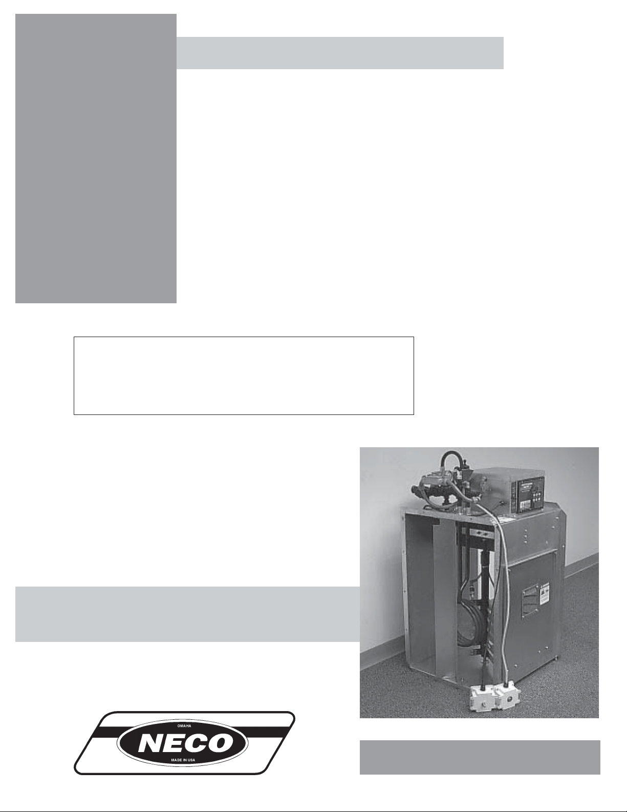
Neco Series Two
Centrifugal Heater
Installation And
Operating Instructions
MODEL # CHN - __ __ - __ __ - 2 __ (HIGH)
MODEL # CLN - __ __ - __ __ - 2 __ (LOW)
Owner's
Manual
MANUAL # PNEG-584
1
Page 2

CHECK LIST
_____ 1. Check all wire connections
_____ 2. Spark plug and flame sensor tightness set plug gap to 1/8"
_____ 3. Check plug in terminal strips on back of circuit board to be sure they are plugged into proper
position.
_____ 4. Software settings correct for type of heater (hi-low , on-off)
_____ 5. Dip switch settings correct for heater model (slave, master)
_____ 6. Most current software version installed
_____ 7. Turn heater toggle switch on. Most current software version should be displayed first, fol
lowed by temperature. Screen should read "NO AIRFLOW".
_____ 8. Turn fan on. Screen should read "AIRFLOW".
_____ 9. Program hi-limit set point to 140 degrees F.
_____ 10. Program cycle set point to 120 degrees F (only on hi-lo units).
_____ 11. Program differential to 10 degrees F/
_____ 12. Turn gas on to heater unit.
_____ 13. Press start switch on heater. Screen should flash "PURGE".
_____ 14. After 10 second purge heater should light screen, and should read "HI-FLAME".
_____ 15. Adjust pressure to 10 psi (lp units) 5 psi (ng units).
_____ 16. Check pipe train for leaks with soapy water.
_____ 17. T emperature should rise to 120 degrees. Screen should read "LO-FLAME" and unit
_____ 18. Adjust pressure with ball valve to 2 psi (lp units) 1 psi (ng units). (hi-lo units only)
_____ 19. On standard units temperature will rise to 140 degrees. Screen will read "OFF-CYCLE".
Heater will shut off at this point.
_____ 20. Temperature will drop 10 degrees and unit will cycle back to hi-flame. Screen should read
"HI-FLAME".
_____ 21. Observe unit go through 3 cycles.
_____ 22. Pull wire off of housing hi-limit switch. Screen should read "ERROR 000" and "HOUSING
TEMP HI-LIMIT". Heater should shut down and lock out. Fan should shut off.
_____ 23. Turn heater toggle switch on. Most current software version should be displayed first,
_____ 24. Turn fan on. Screen should read "AIRFLOW".
_____ 25. Press start switch on heater. Screen should flash "PURGE".
_____ 26. After 10 second purge heater should light. Screen should read "HI-FLAME". "FLAME" should
_____ 27. Shut gas off to heater and allow gas to burn out of system.
_____ 28. 2-4 seconds after flame goes out on heater, "FLAME" in lower right hand corner of screen
should go out. Unit should begin to spark.
_____ 29. After 10 seconds fan and heater should shut down and lock out. Screen should read
_____ 30. Check heater visually to see that all decals are in place and correctly located.
_____ 31. Place owners manual in control box.
SERIES TWO HEATER
"FLAME" should appear on lower right hand corner of screen.
should cycle to lo-flame. (hi-lo units only)
followed by temperature. Screen should read "NO AIRFLOW".
appear on lower right hand corner of screen.
"ERROR 000" and "FLAME OUT".
Tester Signature___________________________________________
Date____________________________________
2
Page 3

SERIES TWO HEATER
Warranty.......................................................................................................................4
Roof W arning, Operation & Safety .....................................................................................5
Safety Alert Decals.......................................................................................................6
Series T wo Heater Installation......................................................................................7
Centrifugal Heater Specifications...........................................................................7
Heater Dimensional Specifications........................................................................7
Plenum T emperature Sensor Mounting.................................................................8
Transition Hi-Limit Installation................................................................................8
Heater Unit W iring..................................................................................................9
Secondary Heater Unit Wiring................................................................................9
Machine T o Earth Ground.....................................................................................10
Proper Installation Of The Ground Rod.................................................................10
Previously Installed Units......................................................................................10
Fuel Connection For Liquid Propane Models.........................................................11
Fuel Connection For Propane V apor Models........................................................1 1
Fuel Connection For Natural Gas Models............................................................11
Series T wo Heater Operating Procedure.........................................................................12
Power Up..............................................................................................................12
Normal Operating Displays With Heater Not Running..........................................13
Starting The Dryer.................................................................................................14
Setting Gas Pressure ............................................................................................14
BTU's Per Gauge Pressure (PSI) Propane Models (Approximate)......................15
BTU's Per Gauge Pressure (PSI) Natural Gas Models (Approximate).................16
Adjusting The V aporizor ........................................................................................17
Programming Set Points.......................................................................................18
Programming Hours T o Shut Down.......................................................................19
Drying Grain In The Hours T o Shut Down Mode...................................................19
Run Hours Display...............................................................................................19
Multiple Heater Notes............................................................................................19
Factory Configuration..................................................................................................20
Configuration Dip Switches (Normally Done At GSI)............................................20
Error Conditions..........................................................................................................21
Limit Switches......................................................................................................21
Multiple Heater Error Conditions...........................................................................21
Misc Error Numbers..............................................................................................21
Series T wo Heater Service..........................................................................................22
Series T wo Heater Wiring..........................................................................................23
Notes...........................................................................................................................24
T ABLE OF CONTENTS
TABLE OF CONTENTS
3
Page 4
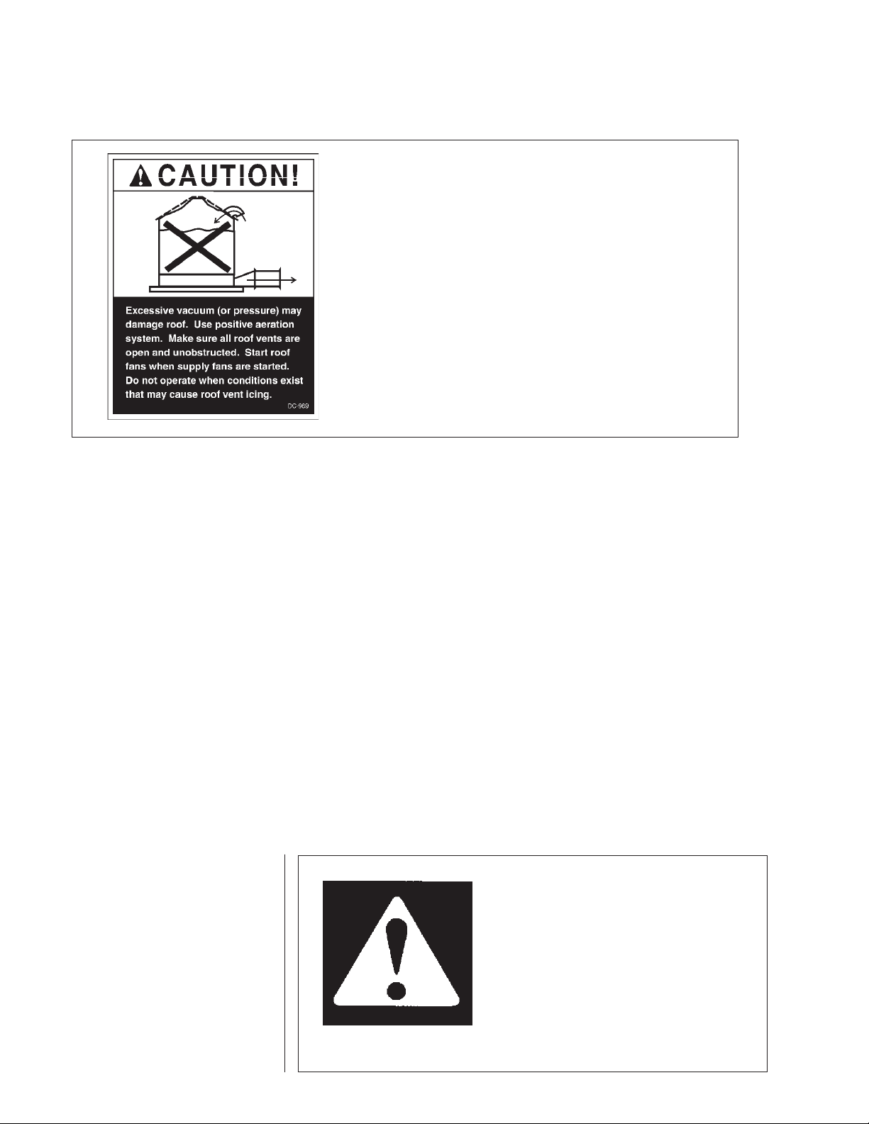
ROOF WARNING AND DISCLAIMER
Roof Damage Warning And Disclaimer
GSI DOES NOT WARRANT ANY ROOF DAMAGE CAUSED
BY EXCESSIVE V ACUUM OR INTERNAL PRESSURE FROM
F ANS OR OTHER AIR MOVING SYSTEMS. ADEQUA TE VENTILA TION AND/OR "MAKEUP AIR" DEVICES SHOULD BE
PROVIDED FOR ALL POWERED AIR HANDLING SYSTEMS.
GSI DOES NOT RECOMMEND THE USE OF DOWNWARD
FLOW SYSTEMS (SUCTION). SEVERE ROOF DAMAGE CAN
RESUL T FROM ANY BLOCKAGE OF AIR P ASSAGES. RUNNING F ANS DURING HIGH HUMIDITY/COLD WEATHER
CONDITIONS CAN CAUSE AIR EXHAUST OR INT AKE PORTS
SERIES TWO HEATER
HEATER OPERATION
Thank you for choosing a Neco product. It is designed
to give excellent performance and service for many
years.
This manual describes the operation of the Neco Series
Two Heater. It is designed for low to medium temperature grain conditioning, and is ideal for the aeration of
rice, popcorn or other select grains. It is available in both
propane vapor and natural gas models.
The principal concern of Neco is your safety and
the safety of others associated with grain handling
equipment. This manual is written to help you under-
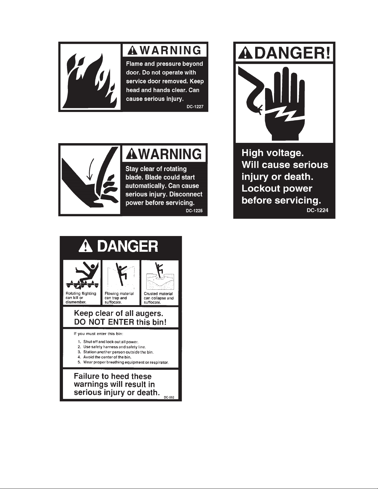
SAFETY ALERT SYMBOL
The symbol shown is used to call
your attention to instructions concerning your personal safety . W atch
for this symbol; it points out important safety precautions. It means
"ATTENTION", "WARNING",
"CAUTION", and "DANGER".
Read the message and be cautious
to the possibility of personal injury
or death.
4
stand safe operating procedures, and some of the problems that may be encountered by the operator or other
personnel.
As owner and/or operator, it is your responsibility to
know what requirements, hazards and precautions exist,
and to inform all personnel associated with the equipment, or who are in the dryer area. Avoid any alterations
to the equipment. Such alterations may produce a very
dangerous situation, where serious injury or death may
occur.
WARNING! BE ALERT!
Personnel operating or working around
electric fans should read this manual.
This manual must be delivered with the
equipment to its owner. Failure to read
this manual and its safety instructions is
a misuse of the equipment.
Page 5
SERIES TWO HEATER
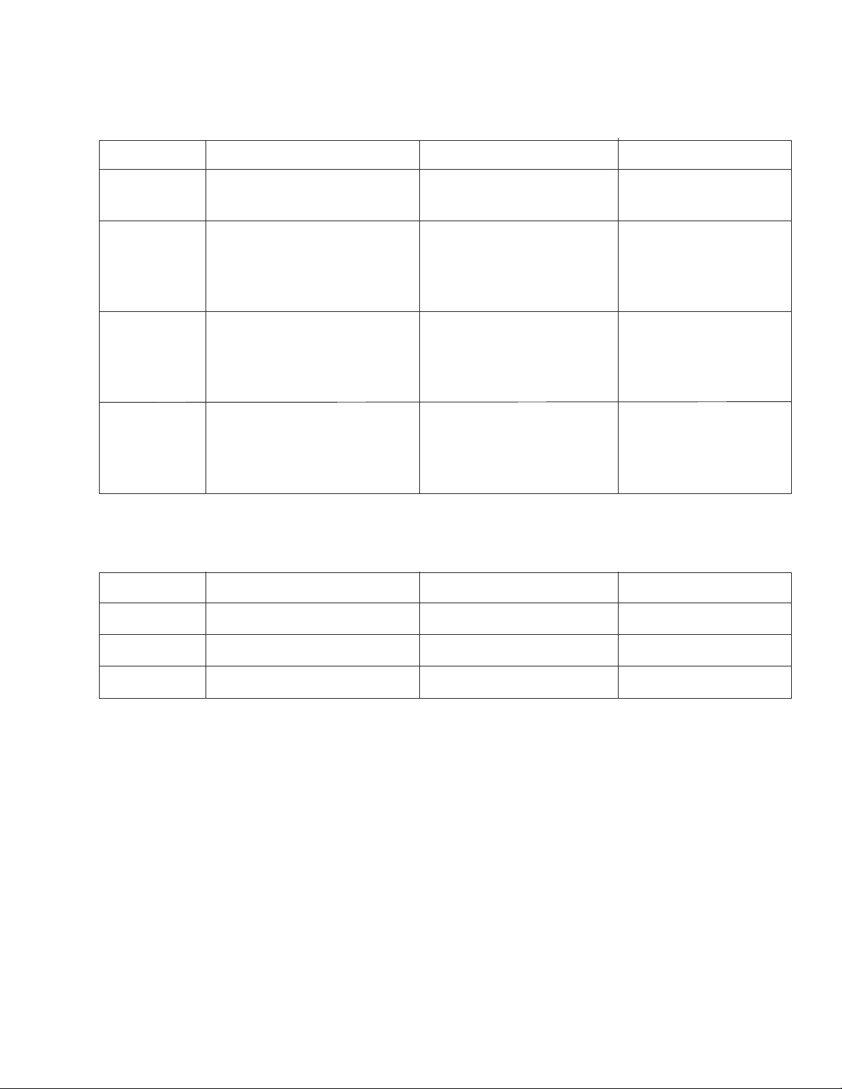
SAFTY ALERT DECALS
IMPOR TANT: Safety decals should be read and
understood by all people in the grain handlng area.
The bottom right decal should be present on the inside
bin door cover and the roof manway cover. If a decal
is damaged or is missing contact:
5
Page 6

SAFTY ALERT DECALS
SAFETY FIRST
General Safety Statements
The GSI Group Inc’ s Principal concern is your
safety and the safety of others associated with grain
handling equipment. W e want to keep you as a customer . This manual is to help you understand safe
operating procedures and some problems which may
be encountered by the operator and other personnel.
As owner and/or operator, it is your responsibility to know what requirements, hazards and precautions exist and inform all personnel associated with,
or in the area of the Fill/Feed System. Safety precautions may be required from the personnel. A void
any alteration to the equipment. Such alterations may
produce a very dangerous situation, where serious
injury or death may occur .
SERIES TWO HEATER
CAUTION
CAUTION used without the safety alert symbol indicates a potentially hazardous situation which, if not
avoided, may result in property damage.
BE ALERT!
Danger!
Personnel operating or working around electrical equip-
ment should read this manual.
This manual must be delivered with equipment to
its owner. Failure to read this manual and its safety
instructions is a misuse of the equipment.
This product is intended for the use of conveying feed only . Any other use is a misuse of the
product!
This is the safety alert symbol.
It is used to alert you to potential personal injury hazards.
Obey all safety messages that
follow this symbol to avoid possible injury
or death.
DANGER
DANGER indicates an imminently hazardous situation
which, if not avoided, will result in death or serious injury
WARNING
WARNING indicates a potentially hazardous situation
which , if not avoided, could result in death or serious
injury.
CAUTION
This product has sharp edges! These sharp
edges may cause serious injury . To avoid injury handle
sharp edges with caution and use proper protective
clothing and equipment at all times.
The GSI Group Inc. recommends that you
contact your local power company and have a representative review your installation so your wiring will
be compatible with their system and so that you will
have adequate power supplied to your unit.
The Chain Disk drive unit weights 159 lbs
(72kg). All precautions should be taken when lifting
and/or moving. Use at least two men when moving
the unit anywhere.
The safety pages that follow are to show you
where you can find the safety decals. The photographs show exactly where the decals should be. If a
decal has been damaged or is missing contact The
GSI Group, Inc. for a free replacement.
CAUTION indicates a potentially hazardous situation which, ifnot avoided, may result in minor or
moderate injury .
6
Page 7
SERIES TWO HEATER
CENTRIFUGAL HEATER SPECIFICATIONS
HEATER INST ALLATION
All models
Liquid models
Vapor models
Natural gas
models
Hi-Temp Model
BTU rating
Weight
Maximum fuel flow (GPH)
Orifice size
Minimum operating pressure
Maximum operating pressure
Minimum line size
Maximum fuel flow (CFH)
Orifice size
Minimum operating pressure
Maximum operating pressure
Minimum line size
Maximum fuel flow (CFH)
Orifice size
Minimum operating pressure
Maximum operating pressure
Minimum line size
4000000
145
43
.25
3
30
3/8"
1590
.25
2
30
1"
4200
.375
1
15
1.1/4"
HEATER DIMENSIONAL SPECIFICATIONS
Lo-Temp Model
500000
135
N/A
N/A
N/A
N/A
N/A
210
.109
1
15
1/2"
500
.156
1
7
1"
Heater Size
Inside Height
Inside Width
Inside length
10-15
30.1/4"
19.1/2"
24"
20-30
33.1/4"
21.3/4"
24"
40
33.1/4"
23.11/16"
24"
7
Page 8
HEATER INST ALLATION
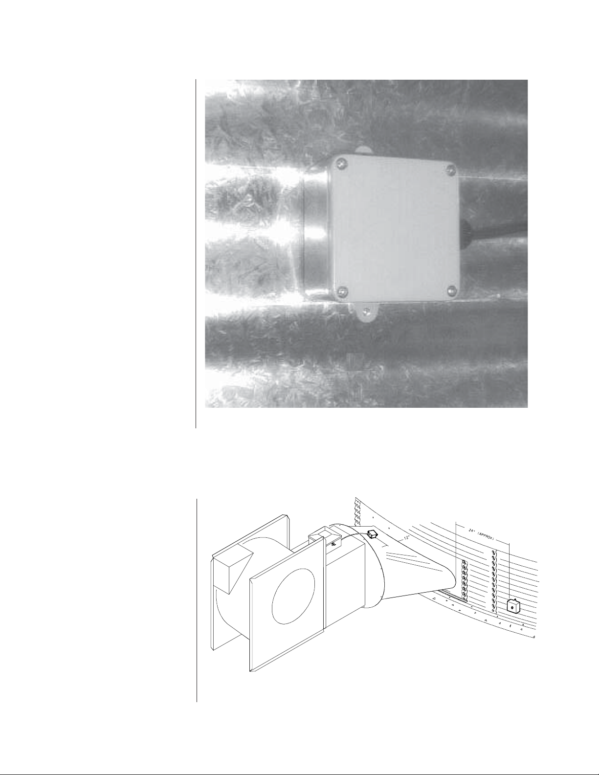
PLENUM TEMPERA TURE
SENSOR MOUNTING
The plenum temperature sensor is
the white PVC junction box with bolt
extending from outside attached by
a cord to the fan/heater control box.
1. 24" to the right side of the transition, drill one 3/8" hole in the center of the plenum in a valley on
the bin sidewall.
2. Insert the probe through the hole.
3. Position the housing so that the
tabs are vertical, and the cord
exits the housing horizontally.
SERIES TWO HEATER
4. Use two self drilling screws to mount
the housing to the bin sidewall.
5. Caulk between the housing and
the sidewall to seal.
TRANSITION HI-LIMIT INSTALLATION
1. Mark location on transition one
(1) foot up from the bottom
(entrance collar) and centered
in the transition.
2. Drill or knock out 7/8" diameter
hole on marked location.
3. Install transition hi-limit using
supplied self drilling screws.
Plenum temperature sensor installation.
Figure 1: The transition connecting the heater to the bin with the plenum
thermostat in place.
8
Page 9
SERIES TWO HEATER
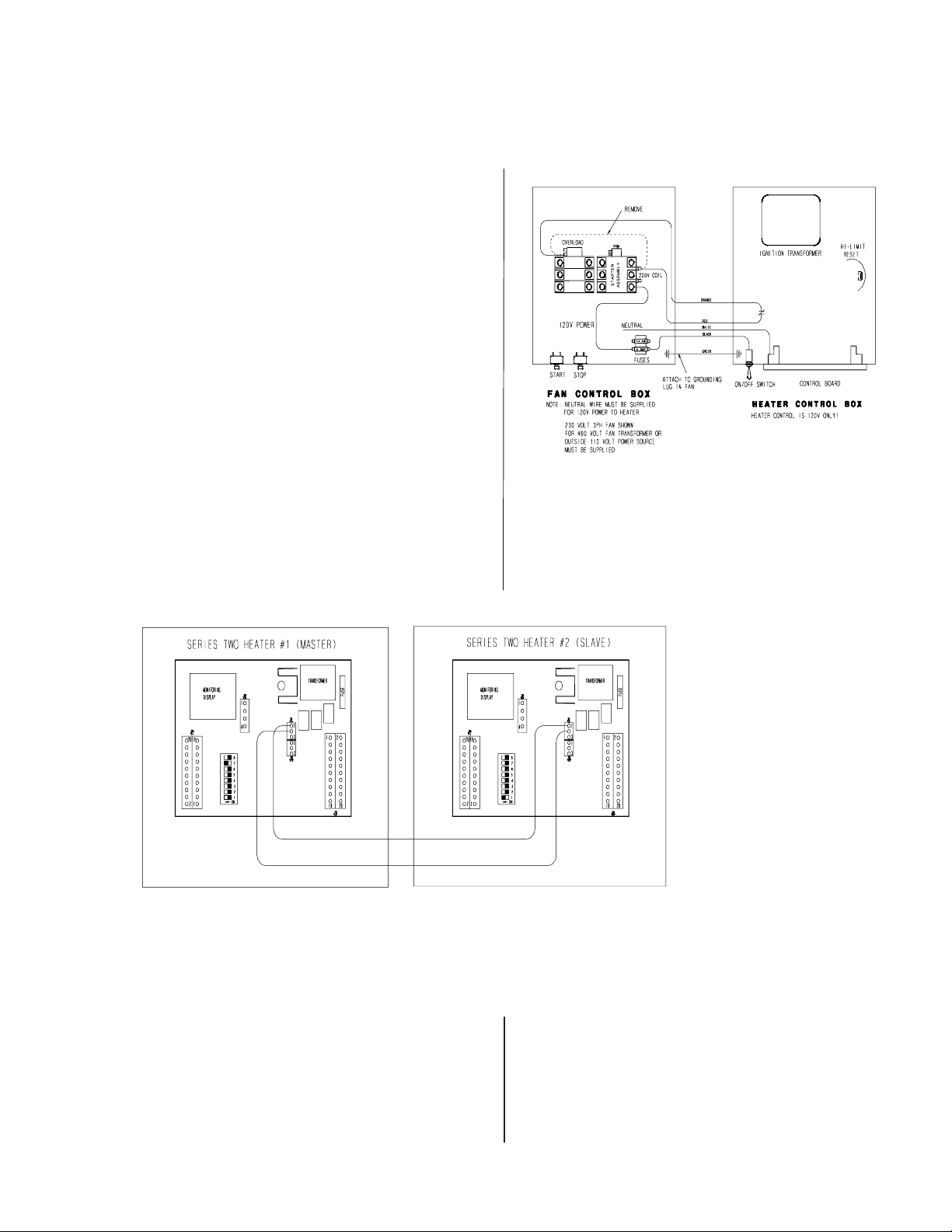
WIRING
HEA TER UNIT
1. Be sure fan unit is installed and wired to meet local
codes. Be sure equipment is well grounded (see page 9).
2. A separate neutral is required for 120 volt heater
circuit in 220 volt 1PH and 3PH fan units. For 460 volt
fan units a separate 120 volt power supply or transformer
is required.
3. Run S-wire black cord from heater unit to fan unit
and secure to fan.
HEATER INST ALLATION
4. Orange and red wires should be connected in series
with coil in fan. When contacts in heater between these
wires open fan shuts down. Recommended wiring is
shown in Figure 2.
5. Black and white wires should be connected to a fused
Figure 2: Wiring diagram for the fan and heater unit.
120V power supply as shown. Green wire should be connected to ground in fan.
Figure 3: Secondary heater wiring diagram.
SECONDARY
HEA TER UNIT
1. Secondary heater unit runs as a slave of heater unit
#1 and re-quires no plenum or grain temperature sensor.
2. Run (2) 20 gauge (minimum) wires from secondary
heater unit (slave) to heater unit #1 (master).
3.
Connect wires as shown in Figure 3.
4. Third heater unit may also be added to system. If
adding third unit, run connections to master unit #1 and
connect them inparallel with secondary heater unit.
9
Page 10

HEATER INST ALLATION
SERIES TWO HEATER
Transformer and Wiring Voltage DropPower Supply
An adequate power supply and proper wiring are
important factors for maximum performance and long
life of the dryer . Electrical service must be adequate
enough to prevent low voltage damage to motors and
control circuits (see Electrical Load Informationon page
40) In 220V 1 ph and 220V 3 ph systems a sepa-
rate neutral wire is required for the 120V heater
circuit, and should be connected to terminal #1 in
the master heater . Do not run in conduit with motor power lines.
Machine To Earth Grounding
It is very important that a Machine T o Earth ground
be installed at the worksite. The complete unit must be
wired and grounded to all local applicable codes. The
proper grounding will provide safty to the operators and
ensure long life to all circuit boards.
It is necessary to know the distance from the unit to
the available transformer, and the horsepower of your
fan unit. Advise the service representative of your local
power supplier that an additional load will be placed on
the line. Each fan motor should be wired through a fused
or circuit breaker disconnect switch. Check the KVA
rating of the transformers, considering horsepower and
load. The power supply wiring , main switch equipment
and transformers must provide adequate motor starting and operating voltage. Voltage drop during startup
should not exceed 14% of normal voltage, and after
motor is running at full speed it should be within 8% of
normal voltage. Check Electrical Load Information for
HP ratings and maximum amp loads to properly size
wire and fusing elements. Standard electrical safty practices and codes should be used. (Refer to National Electrical Code)
10
Page 11

SERIES TWO HEATER
Standard electrical safety practices and codes should
be used when working with a heater. Refer to the
National Electric Code Standard Handbook by the
National Fire Protection Association. A qualified
electrician should make all wiring installations.
HEATER INST ALLATION
IMPORTANT! Do not use propane tanks that have
previously been used for ammonia unless they have
been purged according to procedures of the National L.P . Association.
Fuel supply system must comply with local codes
for L.P . gas installation.
FUEL CONNECTION
LIQUID PROP ANE
MODELS
1. L.P. models are designed to run on liquid propane
with liquid draw from the propane tank. Avoid using
propane supply tanks that have been used for vapor
draw for long periods of time. When using liquid
draw systems any moisture that may be present in
tank or lines may freeze when system is used in cold
weather. To avoid this situation, purge the system
with methanol.
2. Run proper size line (see specification on page 6) to
liquid pipe train on heater. Have a qualified gas ser
vice person inspect installation to be sure that every
thing is installed according to local codes and ordi
nances.
3. After installation is complete check all connections
for leaks with liquid detergent or comparable. Wear
rubber gloves and eye protection. A void contact with
liquid propane. DO NOT USE FLAME FOR LEAK
TESTING.
AL WAYS DISCONNECT AND LOCK OUT
POWER
BEFORE WORKING ON OR AROUND
HEATER
PROP ANE VAPOR
MODELS
1. Propane vapor models are designed to run directly
off of a supply tank or from a separate external va
porizer.
2. Run proper size line (see specifications on page 6) to
pipe train on heater. Have a qualified gas service
person inspect installation to be sure that everything
is installed according to local codes and ordinances.
3. After installation is complete check all connections
for leaks. DO NOT USE FLAME FOR LEAK
TESTING.
NATURAL GAS MODELS
1. Natural gas models are designed to run directly off
of a supply tank or from a separate external vapor
izer.
2. Run proper size line (see specification on page 6) to
pipe train on heater. Have a qualified gas service
person inspect installation to be sure everything is
installed according to local codes and ordinances.
3. After installation is complete check all connections
for leaks. DO NOT USE FLAME FOR LEAK
TESTING.
11
Page 12

HEATER OPOERA TION PROCEDURE
SERIES TWO HEATER
The control panel display showing initial start up.
Standard electrical safety practices and codes should be
used when working with a heater. Refer to the National Electric Code Standard Handbook by the National Fire Protection Association. A qualified elec-
trician should make all wiring installations.
POWER UP
All safety and high limit switches are checked upon power
up. If a safety or limit is open, the control displays it. The
control cannot operate with a safety switch error, and the
fan cannot turn on with an error condition. There is no way
to bypass an error condition. It must be fixed. (see errors on
page 20)
The air switch is also checked on power up. The
air switch must indicate no airflow . This is necessary
to check the function of the air switch. However, if
the opera-tor forgets and turns the fan on before the
controller has been powered up, the controller locks
up with the main display alternating between a "FAN"
and "ON" message. This may be bypassed by depressing and holding the "F AN BYPASS" switch (lower right
switch). Normal operating procedure should be to power
up the controller with the fan off.
If multiple heaters are tied together, and the master detects that the slave fan is on (the air switch
stuck?), the master will lock up displaying "SLA ERROR". This condition may be bypassed with the "F AN
BYPASS" switch.
ALWAYS DISCONNECT
AND LOCK OUT POWER
BEFORE WORKING ON OR
AROUND HEATER
12
Page 13

SERIES TWO HEATER
HEATER OPOERA TION PROCEDURE
NORMAL OPERATING
DISPLAYS WITH HEATER
NOT RUNNING
The main display shows the plenum temperature. If the
dryer has not been running, the display should show outside temperature. The control is preset at the factory to
display temperature in centigrade or fahrenheit "AIRFLOW" or "NO AIRFLOW" is displayed if air is flowing
or not flowing. "RX TX" (receive, transmit) is displayed
if multiple heaters are connected.
its are continuously checked during the off mode. A limit
switch open, or any other error condition will cause the
display to show the limit or error condition. When drying
All safeties or high lim-
is not occurring, and the limit or error condition is corrected, the display returns to its normal
output. This is not the case with an error or limit condition during the drying operation. This causes the display to lock up in the error display mode. This is to
keep the display locked up with the condition illuminated. (see section on "Running the Dryer" for mode
explanation on page 16)
The heater display with fan off ( no airflow).
13
Page 14

HEATER OPOERA TION PROCEDURE
SERIES TWO HEATER
ST ARTING THE DRYER
After heater power is turned on, the
fan must be turned on. Attempting
to start the dryer without the air
switch indicating there is airflow will
cause an airflow alarm to go off when
the start switch is depressed. The airflow alarm is simply the entire display
going blank, and the "NO AIRFLOW"
message flashing for a few seconds.
The display must show "AIRFLOW"
before the dryer can be started.
To start the dryer, just push the
"ST ART" switch. The first message
to come up will be the "PURGE"
message--the drying process begins
with a 10 second purge.
When multiple heaters are connected together, drying may be
started from any heater control.
SETTING GAS PRESSURE
1. At heater turn toggle switch
to "ON" position.
2. Press the "PROGRAM TEM-
PERATURE" button.
3. Use the increase or decrease
button to set the "PLENUM
HIGH LIMIT SET POINT" to
desired setting (100°-160°*).
4. Press the "PROGRAM TEM-
PERA TURE" button to continue
to set the "CYCLE SET
POINT". (hi-lo units only)
5. Use the increase or decrease
buttons to set the "CYCLE SET
POINT" to desired setting
(90°-150°*) (hi-lo units only).
Programming the temperature
differential.
6. Press the "PROGRAM TEMPERA TURE" button to continue
to set the "TEMPERATURE
DIFFERENTIAL".
7. Use the increase or decrease
buttons to set the "TEMPERATURE DIFFERENTIAL" to
10°*.
8. Open all manual gas shut off
valves, on and to the heater unit.
9. Start the fan unit.
10. Make sure that the blade is spinning in the right direction. If not
place the toggle switch in the
"OFF" position and correct the
problem.
11. After the fan reaches full speed
the display should read "AIRFLOW" in the upper right hand
corner.
12. Press the start button on the
heater control.
13. After 10 seconds the burner
should ignite. If not, turn "OFF"
the toggle switch and then back
"ON". Repeat 12-15.
14. When the burner ignites the dis-
play should read "HI-FLAME" at
the left of the display. Loosen the
nut on the main regulator and turn
screw in, to increase pressure and
out to decrease pressure. The
pressure gauge should be set at
10-15 lbs. for LP units, or 4-6 lbs.
for natural gas units. (use the
charts on the following pages to
set pressure)
15. Press the "PROGRAM TEMPERATURE" button to
change the high limit set
point. Press i t
again to change the "CYCLE
SET POINT". (hi-lo units only)
16. Decrease the "CYCLE SET
POINT TEMPERATURE" until
the heater cycles to low flame. (hilo units only)
17 . Open or close the low cycle ball
valve until the gas pressure is
3-5 lbs. for LP, or 1-2 lbs. for
natural gas. (hi-lo units only)
18. Increase the cycle set point to
return to high flame. (hi-lo units only)
19. Watch heater run several min-
utes to make sure it cycles between hi and lo flame or on and
off properly .
20. Hi-flame pressure should be
adjusted so plenum reaches cycling temperature easily .
21. Adjust pressure on on/off units
so that unit is on approximately
75% of the time.
14
*Temperatures are fahrenheit.
Page 15

SERIES TWO HEATER
HEATER OPOERA TION PROCEDURE
10 - 15 HP UNITS
BTU’s Per Gauge Pr essure (PSI)
PROPOANE MODELS
(Approximate)
HIGH TEMPERATURE 10-15hp 7/32" orifice
OPERATING PRESSURE (PSI)
246810121415
ALL
MODELS 816013 1148640 1409477 1632026 1825859 1995762 2153700 2227883
Gauge Pressure (Psi) Required To Maintain Temperature ( Approximate )
( 10-15 Horsepower High Temp Propane Units Only )
Static
Fan Model Pressure 60 80 100 120 140 160 180
2"24681013
10HP 4" 1 3 5 6 8 11 14
6"11356810
2" 3 6 9 12 15
15HP 4" 3 5 7 10 13
6"235691114
Heat Rise De gr ee s F
BTU’s Per Gauge Pressur e (PSI)
NA TURAL GAS MODELS
(Approximate)
HIGH TEMPERA TURE 10-15hp 1 1/32” orifice
OPERA TING PRESSURE (PSI)
1234567
ALL
MODELS 859104 1218432 1489296 1718208 1921584 2107632 2276352
Gauge Pressure (Psi) Required To Maintain Temperature ( Approximate )
( 10-15 Horsepower High Temp Natural Gas Units Only )
Static
Fan Model Pressure 60 80 100 120 140 160 180
2" 1 1.75 2.5 3.5 4.75 6
10HP 4" 0.75 1.25 2 2.75 3.75 4.75 6
6" 0.5 1 1.5 2 2.75 3.5 4.25
2" 1.5 2.5 3.75 5.5
15HP 4" 1.25 2 3 4.25 5.75
6" 0.75 1.25 2 2.75 3.75 5 6
Heat Rise De gr ee s F
15
Page 16

HEATER OPOERA TION PROCEDURE
SERIES TWO HEATER
20 - 40 HP UNITS
BTU’ s Per Gauge Pressure (PSI) PROP ANE MODELS (Appr oximate)
HIGH TEMPERA TUR E 20-4 0hp 5/16" or ifice
OPERATING PRESSURE (PSI)
2 4 6 8 10 12 14 15
ALL
MODELS 1663135 2345140 2878779 3328663 3721115 4068100 4393548 4541914
Gauge Pressure (Psi) Required To Maintain Temperature ( Approximate )
( 20-40 Horsepower High Temp Propane Units Only )
Static
Fan Model Pressure 60 80 100 120 140 160 180
2"22457810
20HP 4"1234578
6"1234567
2"235791215
25HP 4" 2 3 4 6 8 10 13
6"22456810
2"24681115
30HP 4" 2 4 5 7 10 13
6"234681013
2"36812
40HP 4" 3 5 7 11 14
6"347912
Heat Rise Degr ees F
BTU’s Per Gauge Pressur e (PSI) NA TURAL GAS MODELS (Approximate)
HIGH TEMPERA TURE 20-40hp 15/32” orifice
OPERA TING PRESSURE (PSI)
1234567
ALL
MODELS 1597824 2266320 2770656 3195648 3573216 3919776 4234416
Gauge Pressure (Psi) Required To Maintain Temperature ( Approximate )
( 20-40 Horsepower High Temp Natural Gas Units Only )
Static
Fan Model Pressure 60 80 100 120 140 160 180
2" 0.75 1.25 1.75 2.5 3.25 4.25 5.5
20HP 4" 0.5 1 1.5 2 2.75 3.5 4.5
6" 0 .5 0.75 1.25 1.75 2.25 3 3.75
2" 1 1.75 2.25 3.5 4.75 6.25
25HP 4" 0.75 1.5 2.25 3.25 4 5.25 6.25
6" 0.5 1.25 1.75 2.5 3.25 4.25 5.5
2" 1.25 2 3 4.5 6
30HP 4" 1 1.75 2.75 3.75 5 7
6" 0.75 1.5 2.25 3 4 5.25 7
2" 1.75 3 4.5 6.25
40HP 4" 1.5 2.5 4 5.5
6" 1.25 2.25 3.5 4.75 6.75
Heat Rise Degr ees F
16
Page 17

SERIES TWO HEATER
HEATER OPOERA TION PROCEDURE
Lo Temp Units
BTU’s Per Gauge Pr essure (PSI)
PROP ANE MODELS
(Approximate)
LOW TEMPERA TURE ALL HP’s 7/64” orifice
OPERA TING PRESSURE (PSI)
246810121415
ALL
MODELS 203405 287160 351771 409203 457063 497744 538425 555176
BTU’s Per Gauge Pr essure (PSI)
NA TURAL GAS MODELS
(Approximate)
LOW TEMPERA TURE ALL HP’s 5/32” orifice
OPERA TING PRESSURE (PSI)
1234567
ALL
MODELS 177840 251712 308256 355680 397632 435936 470592
17
Page 18

HEATER OPOERA TION PROCEDURE
SERIES TWO HEATER
ADJUSTING THE
VAPORIZOR
1. V aporizer should be adjusted so
the vapor pipe train runs warm
to the touch (100°-120°F).
2. Loosen 5/16" bolts on adjustment bracket.
3. Raise vaporizer if running too
hot, lower if too cold.
4. Move vaporizer only 1" at a
time and allow a few minutes for
temperature to equalize.
5. Tighten 5/16" bolts and watch
heater run for several minutes
to verify adjustment.
18
Adjusting the vaporizer coil on a liquid propane model.
The top photo shows the setting up (cool),
and the bottom photo shows the coil down (hot).
Page 19

SERIES TWO HEATER
HEATER OPOERA TION PROCEDURE
The limits are continuously checked during the drying operation. A limit switch open or any other error
condition will cause the dryer to shut down, and the fan
will be shutdown. If a limit opens, or an error condi-
tion occurs during drying, the control will lockup in
the error display mode. Power must be shut off and
back on to the control to clear the error condition--
even if the error or limit that caused the shutdown
has been corrected. This is to keep the display locked up
with the condition that caused the error, allowing the operator time to determine what caused the shutdown.
PROGRAMMING SET POINTS
Depressing the "PROGRAM" switch (lower left) causes
the display to enter the program mode. Each item below
is programmed by using the up and down arrow switches.
Holding down these up and down arrow switches for
about 2 seconds will cause the numbers to increase/decrease rapidly until the switch is released. When finished programming an item, depressing the "PROGRAM"
switch again will cause the new setting to be entered into
memory, and the display will advance to the next function to be programmed.
Programming may be done at
anytime (unless an error condition exists) even while the dryer
is in operation.
Programming a system with
multiple heaters may be done at any
heater control console. The information programmed is automatically
transmitted to all other heaters when
the programming is complete.
Hi Limit Set Point--The upper
left cursor is flashing indicating the
mode. If the plenum temperature
increases above this point, the flame
is shut off--"OFF-CYCLE" is displayed on screen.
Cycle Set Point--The upper 2nd
from left cursor is flashing indicat-
ing the mode. If the dryer is not a hi-lo dryer, this
function is skipped. If the plenum temperature increases
above this point, the flame reduces to "LO-FLAME".
Humidity Set Point--The upper 2nd from right cursor is flashing indicating the mode. If the humidity is
above this point the dryer operates normally--flame on
and off at the high limit and cycle set points. If the humidity is below this point the dryer goes into the "OFFCYCLE" mode. Note: At this time a true humidity
sensor has not been introduced. To use this option,
set the humidity setting to 50% and use a humidistat
switch. When the humidity is high the switch is closed,
indicating high humidity. At this setting, the dryer runs
normally .
Temperature Differential--The upper right cursor is
flashing indicating the mode. If the flame shuts off because
the temperature is greater than the high limit set point, the
temperature must fall below the (Set Point minus T emperature Differential) for the flame to come back on.
Programming the high-limit set point.
19
Page 20

HEATER OPOERA TION PROCEDURE
PROGRAMMING HOURS TO SHUT DOWN
On hi-lo units when the unit reaches cycle set point,
the flame will switch to lo-flame and unit will not cycle
back to hi-flame until (Set Point minus T emperature Differential) is reached.
Temperature differential would normally be set for
10-15 degrees F for high temp units, and 2-5 degrees F
for lo-temp units.
Humidity Differential--The upper right cursor is
flashing indicating the mode. If the flame shuts off
because
the humidity must rise above the (Set Point plus Humidity Differential) for the flame to come back on.
the humidity is less than the humidity set point,
To change the hours to shut down, depress and hold the
"SHUTDOWN HOURS" switch. While holding in on
the switch, depress the up and down arrow switches to
alter the hours. Setting range is 0 to 200 hours.
DRYING GRAIN IN THE HOURS TO SHUT
While drying grain, depress and hold the "SHUTDOWN
HOURS" switch. While holding in on that switch, depress the "START" switch. After depressing the start
switch one time, the heater is in the shutdown mode. Then,
SERIES TWO HEATER
DOWN MODE
the fan and heater shut down when
the time expires. This is indicated by
the lower left cursor flashing.
Depressing the start switch again
(while holding in on the "SHUTDOWN HOURS" switch) will cause
only the heater to shut off. This leaves
the fan on when the time expires. This
is indicated by the 2nd from lower left
cursor flashing. Depressing the start
switch one more time returns the
heater into the continuous--non-shutdown mode.
20
RUN HOURS DISPLA Y
Run hours are recorded when the
controller detects that the fan is on
(airflow). The hours may be viewed
by depressing the "HOURS" to get
hours and "HOURS X 1000" to get
the number of 1000 hours accumulated.
MUL TIPLE HEATER NOTES
When multiple heaters are connected
together, the temperature and humidity sensors must be connected to the
master.
Setting the cycle set point.
Page 21

SERIES TWO HEATER
F ACTORY CONFIGURATION
CONFIGURATION DIP
SWITCHES (NORMALLY
DONE AT FACTORY)
These switches are used to configure the heater control for various
types of heaters.
Stand alone heater
with no slaves, all
dip switches in the
off state.
Multiple heaters connected together through the serial link.
Master with one
slave-dip switch 7
on/all others off.
Master with two
slaves-dip switch 8
on/all others off.
Slave #1-dip switch
one on/all others
off.
Slave #2-dip switch
two on/all others
off.
Master with 3
slaves-dip switch 7
& 8 on/all others
off.
Slave #3-dip switch
one & two on/all
others off.
The backside of the control board, showing the dip switch placement.
21
Page 22

ERROR CONDITIONS
SERIES TWO HEATER
LIMIT SWITCHES
The following limit switch errors light
up individually on the heaters LCD
screen: PLENUM, HOUSING, V APOR, TEMP HI LIMIT.
Note: When a shutdown does occur due to an error condition, the
amount of time elapsed since the shut-
down can be viewed by pressing the
down arrow switch (up to 218 hours).
MULTIPLE HEATER ERROR
CONDITIONS
If two or more heaters are connected
together through the serial link, and the
master cannot communicate with
a slave controller, the master will display "SLA" on the main display and
the "RX" "TX" symbols will be flashing.
If a limit switch error or one of the
error numbers 1 through 8 occurs,
that error is displayed on the slave
where the error originates. The master displays "SLA ERROR".
MISC ERROR NUMBERS
1 2 3 4 5 6
Temperature
probe 1 open.
7
Temperature
probe 1 short.
8 9 10 11 12
Temperature
probe 2 open.
Temperature
probe 2 short.
Airflow open.
Airflow short.
Illegal flame sense.
Error 7 is
most likely caused
by stuck open
solenoid. Error 7
will not shut
down fan until
loss of flame is
detected by
control.
13
+11 volt DC
shorted to ground.
The heater
control display
showing error
000.
Flame probe short
error.
000
This indicates that
one of the other
on screen errors
(vapor, plenum or
housing temp hilimit or flame out
or no airflow has
occured.
Slave #1 inconsistent with master
with either the
drying grain flag or
the LP main solenoid or cycle solenoid.
Most likely the
slave got reset
powering up with
the solenoids off.
(Errors 9 through 11 are displayed only if multiple heaters are tied
together through serial link).
Note: Temperature sensor connection -the temperature
sensor (bolt) must always be connected to the master.
Slave #2 inconsistent. Same as
error 9 for slave
#1.
Slave #3 inconsistent. Same as
error 9 for slave
#1.
Wrong voltage.
Dip switch
#5 is the voltage
selector switch. If
dip switch #5 in
"ON" that selects
240 VAC. If the
unit has only 120
VAC applied, error 12 will show
up. If dip switch
#5 is"OFF" that
selects 120 VAC.
If the unit has 240
VAC applied error
12 will show up.
This is important because if
the heater is set
up at NECO for
120 VAC and the
customer connects
to 240 VAC the
heater control
will work, but if
allowed to operate
the solenoids will
have 240 VAC applied to them
which will damage
solenoids.
22
Page 23

SERIES TWO HEATER
HEATER SERVICE
All NECO heaters are constructed of durable weatherresistant materials, so a minimum amount of service
should be required; however before the unit is started
for the first time each season there are a few items
that need to be checked out. All damaged parts should
be repaired or replaced.
1. Disconnect and lock out power to fan and heater.
Open control box lid and inspect all components for
moisture, vibration or rodent damage. Inspect and
tighten all loose terminal connections. Replace any
damaged wiring.
2. Remove burner orifice tube and inspect for dirt or
foreign material. Clean out if necessary.
3. Inspect burner for wear or foreign material in any of
the ports. Clean or replace parts if necessary .
4. Inspect the spark plug and flame probe for corrosion
and damage. Clean or replace if necessary.
The Series Two control box.
23
Page 24

HEATER WIRING
SERIES TWO HEATER
24
Page 25

SERIES TWO HEATER
______________________________________________________________________________________________________
_______________________________________________________________________________________________________
______________________________________________________________________________________________________
__________________________________________________________________________________________________________
___________________________________________________________________________________________________________
__________________________________________________________________________________________________________
________________________________________________________________________________________________________
__________________________________________________________________________________________________________
_________________________________________________________________________________________________________
NOTES
_______________________________________________________________________________________________________
_________________________________________________________________________________________________________
_______________________________________________________________________________________________________
__________________________________________________________________________________________________
___________________________________________________________________________________________________
_____________________________________________________________________________________________________
____________________________________________________________________________________________________
________________________________________________________________________________________________________
_______________________________________________________________________________________________________
________________________________________________________________________________________________________
_________________________________________________________________________________________________________
________________________________________________________________________________________________________
______________________________________________________________________________________________________
________________________________________________________________________________________________________
____________________________________________________________________________________________________
_______________________________________________________________________________________________________
______________________________________________________________________________________________________
___________________________________________________________________________________________________________
25
Page 26

WARRANTY
NECO WARRANTS ALL PRODUCTS MANUFACTURED BY NECO TO BE FREE OF DEFECTS IN MATERIAL AND WORKMANSHIP UNDER NORMAL USAGE AND CONDITIONS FOR A PERIOD OF 36 MONTHS
AFTER RETAIL SALE TO THE ORIGINAL END USER OF SUCH PRODUCTS. NECO'S ONLY OBLIGATION
IS, AND PURCHASER'S SOLE REMEDY SHALL BE FOR NECO, TO REPAIR OR REPLACE, AT NECO'S
OPTION AND EXPENSE, PRODUCTS THAT, IN NECO'S SOLE JUDGMENT, CONTAIN A MATERIAL DEFECT DUE TO MATERIALS OR WORKMANSHIP. ALL DELIVERY AND SHIPMENT CHARGES TO AND
FROM NECO'S FACTORY WILL BE PURCHASER'S RESPONSIBILITY. EXPENSES INCURRED BY OR ON
BEHALF OF THE PURCHASER WITHOUT PRIOR WRITTEN AUTHORIZATION FROM AN AUTHORIZED EMPLOYEE OF NECO SHALL BE THE SOLE RESPONSIBILITY OF THE PURCHASER.
EXCEPT FOR THE ABOVE STATED EXPRESS LIMITED WARRANTIES, NECO MAKES NO WARRANTY
OF ANY KIND, EXPRESSED OR IMPLIED, INCLUDING, WITHOUT LIMITATION, WARRANTIES OF MERCHANTABILITY OR FITNESS FOR A PARTICULAR PURPOSE OR USE IN CONNECTION WITH (i) PRODUCT MANUFACTURED OR SOLD BY NECO OR (ii) ANY ADVICE, INSTRUCTION, RECOMMENDATION OR
SUGGESTION PROVIDED BY AN AGENT, REPRESENTATIVE OR EMPLOYEE OF NECO REGARDING OR
RELATED TO THE CONFIGURATION, INSTALLATION, LAYOUT, SUITABILITY FOR A PARTICULAR PURPOSE, OR DESIGN OF SUCH PRODUCT OR PRODUCTS.
SERIES TWO HEATER
IN NO EVENT SHALL NECO BE LIABLE FOR ANY DIRECT, INDIRECT, INCIDENTAL OR CONSEQUENTIAL DAMAGES, INCLUDING, WITHOUT LIMITATION, LOSS OF ANTICIPATED PROFITS OR BENEFITS. PURCHASER'S SOLE AND EXCLUSIVE REMEDY SHALL BE LIMITED TO THAT STATED ABOVE,
WHICH SHALL NOT EXCEED THE AMOUNT PAID FOR THE PRODUCT PURCHASED. THIS WARRANTY
IS NOT TRANSFERABLE AND APPLIES ONLY TO THE ORIGINAL PURCHASER. NECO SHALL HAVE NO
OBLIGATION OR RESPONSIBILITY FOR ANY REPRESENTATIVE OR WARRANTIES MADE BY OR ON
BEHALF OF ANY DEALER, AGENT OR DISTRIBUTOR OF NECO.
NECO ASSUMES NO RESPONSIBILITY FOR FIELD MODIFICATIONS OR ERECTION DEFECTS WHICH
CREATE STRUCTURAL OR STORAGE QUALITY PROBLEMS. MODIFICATIONS TO THE PRODUCT NOT
SPECIFICALLY COVERED BY THE CONTENTS OF THIS MANUAL WILL NULLIFY ANY PRODUCT WARRANTY THAT MIGHT HAVE BEEN OTHERWISE AVAILABLE.
THE FOREGOING WARRANTY SHALL NOT COVER PRODUCTS OR PARTS WHICH HAVE BEEN
DAMAGED BY NEGLIGENT USE, MISUSE, ALTERATION OR ACCIDENT. THIS WARRANTY COVERS
ONLY PRODUCTS MANUFACTURED BY NECO. THIS WARRANTY IS EXCLUSIVE AND IN LIEU OF ALL
OTHER WARRANTIES EXPRESS OR IMPLIED. NECO RESERVES THE RIGHT TO MAKE DESIGN OR
SPECIFICATION CHANGES AT ANY TIME.
PRIOR TO INSTALLATION, PURCHASER HAS THE RESPONSIBILITY TO RESEARCH AND COMPLY
WITH ALL FEDERAL, STATE AND LOCAL CODES WHICH MAY APPLY TO THE LOCATION AND INSTALLATION.
26
Page 27

SERIES TWO HEATER
Neco
Box 12277, 9364 N. 45 St.
Omaha, Nebraska 68112
phone 402-453-6912
fax 402-453-0471
February 1999
27
 Loading...