

Page 1
SEREIS ONE HEATER
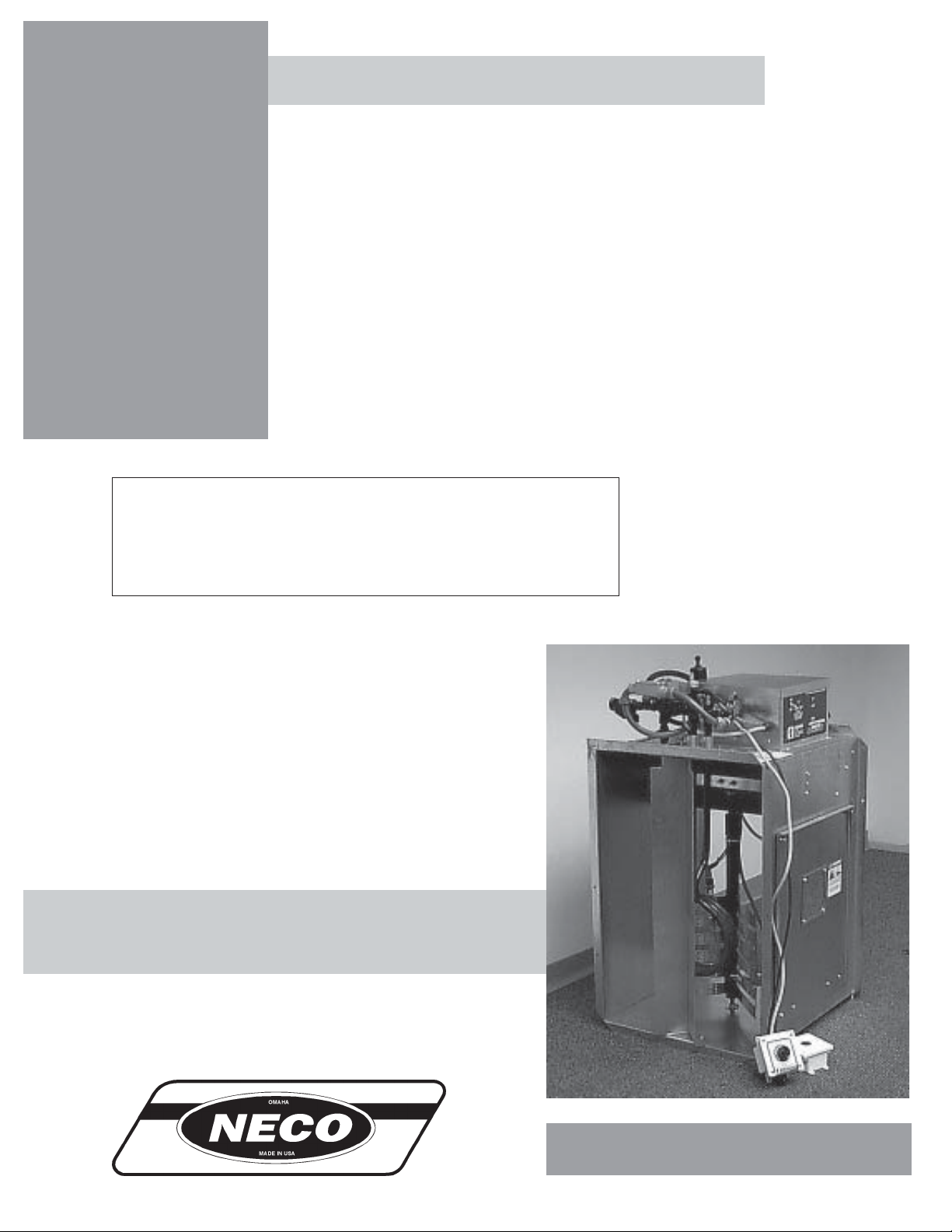
Neco Series One
Centrifugal Heater
Installation And
Operating Instructions
MODEL # CHN - __ __ - __ __ - D (HIGH)
MODEL # CLN - __ __ - __ __ - D (LOW)
Owner's
Manual
MANUAL # PNEG-583
Version 2 2/99
1
Page 2

SEREIS ONE HEATER
CENTRIFUGAL HEATER CHECK LIST
_____ 1. All wire connections
_____ 2. Spark plug gap - .125
_____ 3. Pipe train tightness and gas leaks
_____ 4. Flame sensor tight
_____ 5. Fuse in place, extra fuse provided
_____ 6. Flame out light
_____ 7. Indicator light
_____ 8. Pressure gauge
_____ 9. Regulator adjusted
_____ 10. Shut off valve operates correctly
_____ 11. Vapor high limit
_____ 12. Unit cycles ON to OFF
_____ 13. Heat rise even across transition
_____ 14. Unit cycles HI to LO (HI-LO only)
_____ 15. Mod valve holds temp within 1 degree (mod units only)
_____ 16. All decals and serial number tag
_____ 17. Aesthetic appearance
_____ 18. Manual
Tester Signature___________________________________________
Date____________________________________
2
Page 3

SEREIS ONE HEATER
CENTRIFUGAL HEATER OPERATING INSTRUCTIONS
Warranty.......................................................................................................................4
Roof Warning, Operation & Safety...............................................................................5
Safety Alert Decals.......................................................................................................6
Centrifugal Heater Installation......................................................................................7
Fuel Connection.....................................................................................................7
Heater Electrical Installation (230V Fans)..............................................................8
Heater Electrical Installation (460V Fans)..............................................................9
Plenum Thermostat Mounting...............................................................................10
Transition Hi-Limit Installation................................................................................10
TABLE OF CONTENTS
Temperature Heater Specifications......................................................................11
Heater Dimensional Specifications.......................................................................11
Centrifugal Heater Operating Procedure..........................................................................12
Standard Heater Operation..................................................................................12
Hi-Lo Heater Operation.........................................................................................12
BTU's Per Gauge Pressure (PSI) Propane Models (Approximate)......................13
BTU's Per Gauge Pressure (PSI) Natural Gas Models (Approximate).................14
Adjusting The Vaporizor........................................................................................15
Centrifugal Heater Wiring Diagram.............................................................................16
Second Heater Installation..........................................................................................17
Notes...........................................................................................................................18
3
Page 4
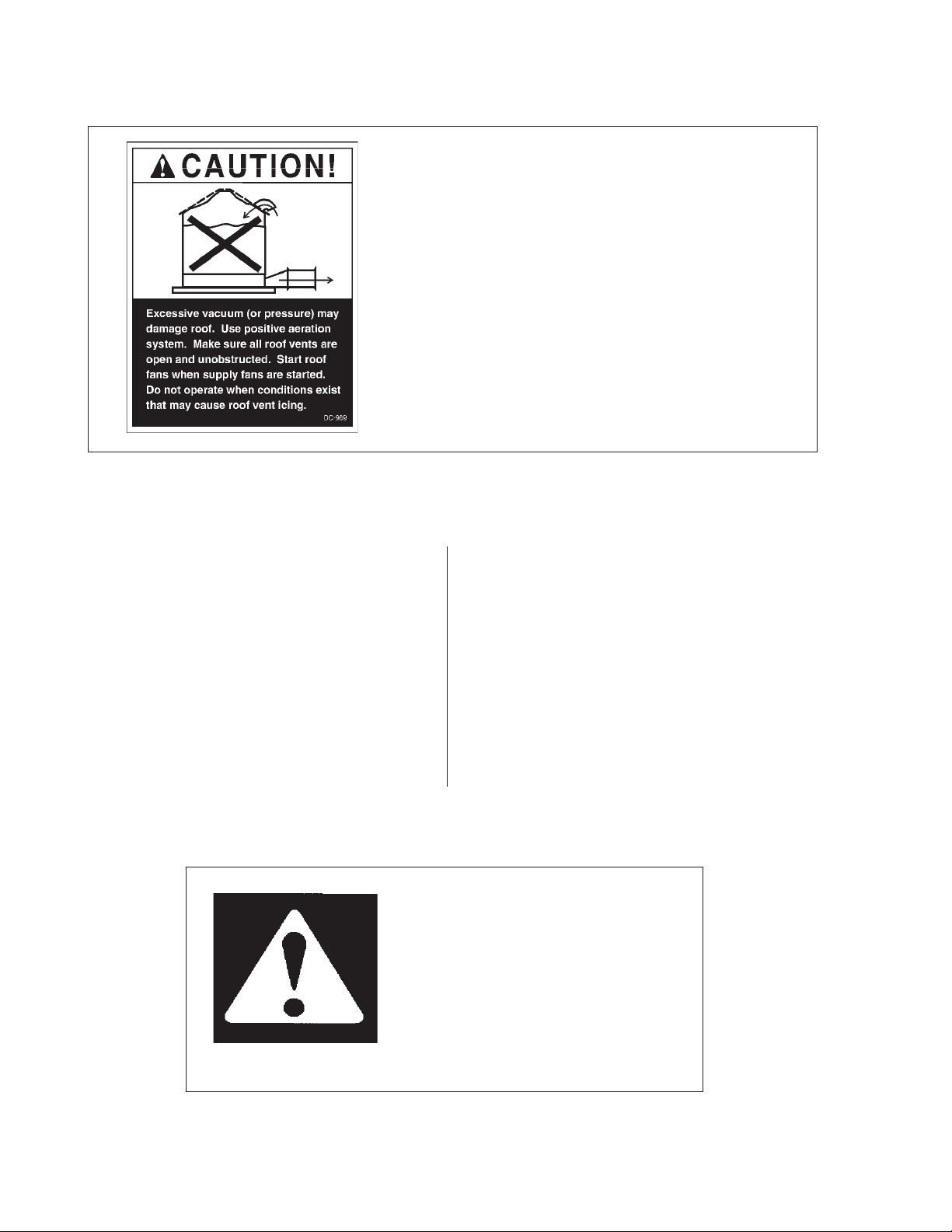
ROOF WARNING AND DISCLAIMER
Roof Damage Warning And Disclaimer
GSI DOES NOT W ARRANT ANY ROOF DAMAGE CAUSED
BY EXCESSIVE VACUUM OR INTERNAL PRESSURE FROM
FANS OR OTHER AIR MOVING SYSTEMS. ADEQUA TE VENTILA TION AND/OR "MAKEUP AIR" DEVICES SHOULD BE
PROVIDED FOR ALL POWERED AIR HANDLING SYSTEMS.
GSI DOES NOT RECOMMEND THE USE OF DOWNWARD
FLOW SYSTEMS (SUCTION). SEVERE ROOF DAMAGE CAN
RESUL T FROM ANY BLOCKAGE OF AIR PASSAGES. RUNNING F ANS DURING HIGH HUMIDITY/COLD WEATHER
CONDITIONS CAN CAUSE AIR EXHAUST OR INT AKE PORTS
SEREIS ONE HEATER
HEATER OPERATION
Thank you for choosing a Neco product. It is designed
to give excellent performance and service for many
years.
This manual describes the operation of the Neco Series
One Centrifugal Heater. It is designed for low to medium
temperature grain conditioning, and is ideal for the aeration
of rice, popcorn or other select grains.
It is available in both propane vapor and natural gas
models.
The principal concern of Neco is your safety and the
safety of others associated with grain handling equipment.
SAFETY ALERT SYMBOL
WARNING! BE ALERT!
Personnel operating or working around
electric fans should read this manual.
This manual must be delivered with the
equipment to its owner. Failure to read
this manual and its safety instructions is
This manual is written to help you understand safe operating procedures, and some of the problems that may be
encountered by the operator or other personnel.
As owner and/or operator, it is your responsibility to
know what requirements, hazards and precautions exist,
and to inform all personnel associated with the equipment, or who are in the dryer area. Avoid any alterations
to the equipment. Such alterations may produce a very
dangerous situation, where serious injury or death may
occur.
The symbol shown is used to call your attention to instructions concerning your personal safety. Watch for this
symbol; it points out important safety precautions. It means "ATTENTION", "WARNING", "CAUTION", and
"DANGER". Read the message and be cautious to the possibility of personal injury or death.
4
Page 5
SEREIS ONE HEATER
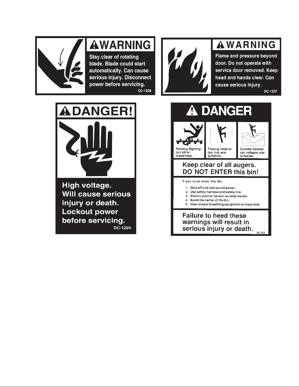
SAFTY ALERT DECALS
IMPOR TANT: Safety decals should be read and understood by all people in the grain handlng area. The
bottom right decal should be present on the inside bin door cover and the roof manway cover. If a decal is
damaged or is missing contact:
5
Page 6
SAFTY ALERT DECALS
SAFETY FIRST
General Safety Statements
The GSI Group Inc’ s Principal concern is your
safety and the safety of others associated with grain
handling equipment. W e want to keep you as a customer . This manual is to help you understand safe
operating procedures and some problems which may
be encountered by the operator and other personnel.
As owner and/or operator, it is your responsibility to know what requirements, hazards and precautions exist and inform all personnel associated with,
or in the area of the Heater System. Safety precautions may be required from the personnel. Avoid any
alteration to the equipment. Such alterations may produce a very dangerous situation, where serious injury
or death may occur .
SEREIS ONE HEATER
CAUTION
CAUTION used without the safety alert symbol indicates a potentially hazardous situation which, if not
avoided, may result in property damage.
BE ALERT!
Danger!
Personnel operating or working around electrical equip-
ment should read this manual.
This manual must be delivered with equipment to
its owner . Failure to read this manual and its safety
instructions is a misuse of the equipment.
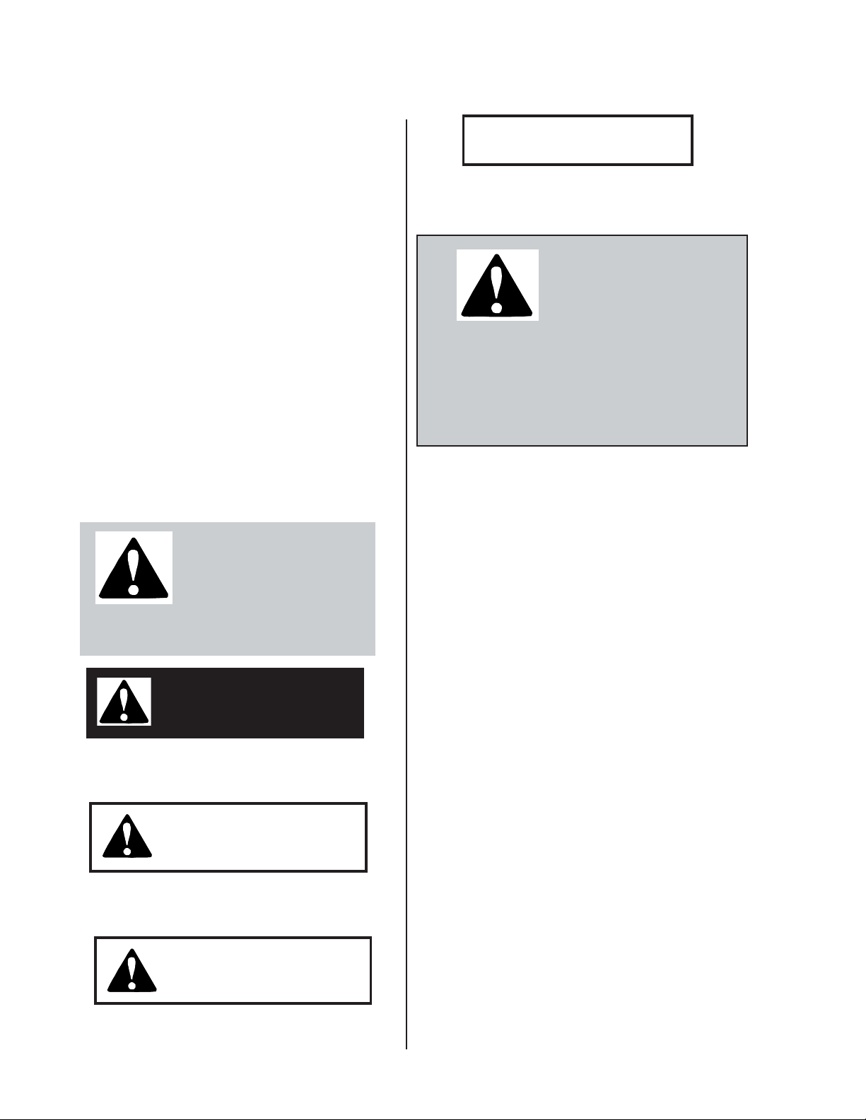
This is the safety alert symbol.
It is used to alert you to potential personal injury hazards.
Obey all safety messages that
follow this symbol to avoid possible injury
or death.
DANGER
DANGER indicates an imminently hazardous situation
which, if not avoided, will result in death or serious injury
WARNING
WARNING indicates a potentially hazardous situation
which , if not avoided, could result in death or serious
injury.
This product has sharp edges! These sharp
edges may cause serious injury . To avoid injury handle
sharp edges with caution and use proper protective
clothing and equipment at all times.
The GSI Group Inc. recommends that you
contact your local power company and have a representative review your installation so your wiring will
be compatible with their system and so that you will
have adequate power supplied to your unit.
The Chain Disk drive unit weights 159 lbs
(72kg). All precautions should be taken when lifting
and/or moving. Use at least two men when moving
the unit anywhere.
The safety pages that follow are to show you
where you can find the safety decals. The photographs show exactly where the decals should be. If a
decal has been damaged or is missing contact The
GSI Group, Inc. for a free replacement.
CAUTION
CAUTION indicates a potentially hazardous situation which, ifnot avoided, may result in minor or
moderate injury.
6
Page 7
SEREIS ONE HEATER
HEATER INST ALLATION
FUEL CONNECTION
Important! Do not use propane tanks which have previously
been used for ammonia unless they have been purged according to procedures of the National L. P. Association.
Be sure fuel supply system complies with all local codes
for L. P. gas installations.
LIQUID PROP ANE
MODELS
1. LP models are designed to run on liquid propane, with
liquid draw from the propane tank.A void using propane supply tanks that have been used for vapor
draw for long periods of time. When using liquid draw
systems any moisture that may be present in tank or
lines may freeze when system is used in cold weather.
T o avoid this, the usual precaution is to purge the
system with methanol.
2. Run proper size line (see specifications) to liquid pipe
train on heater. Have a qualified gas service man
inspect installation to be sure that everything is installed according to local codes and ordinances.
3. After installation is complete check all connections
for leaks with liquid detergent or comparable. Wear
rubber gloves and eye protection. Avoid contact
with liquid propane. DO NOT USE FLAME FOR
LEAK TESTING.
PROP ANE VAPOR MODELS
2. Run proper size line (see specifications) to pipe train
on heater. Have a qualified gas service person in
spect installation to be sure everything iinstalled according to local codes and ordinances.
3. After installation is complete check all connections
for leaks. DO NOT USE FLAME FOR LEAK
TESTING. (see above for other precautions.)
NATURAL GAS MODELS
1. Natural gas models are similar to vapor models, but
have a larger orifice to accommodate lower pres
sure sometimes found with natural gas.
2. Run proper size line (see specifications) to pipe train
on heater. Have a qualified gas service
man inspect installation to be sure everything is in
stalled according to local codes and ordinances.
3. After installation is complete check all connections
for leaks. DO NOT USE FLAME FOR LEAK
TESTING. (See above for other precautions.)
1. Propane vapor models are designed to run directly
off of supply tank or from a separate external vapor1izer .
7
Page 8

HEATER INST ALLATION
SEREIS ONE HEATER
Transformer and Wiring Voltage DropPower Supply
An adequate power supply and proper wiring are
important factors for maximum performance and long
life of the dryer . Electrical service must be adequate
enough to prevent low voltage damage to motors and
control circuits. In 220V 1 ph and 220V 3 ph systems
a separate neutral wire is required for the 120V
heater circuit, and should be connected to terminal
#1 in the master heater . Do not run in conduit with
motor power lines.
Machine To Earth Grounding
It is very important that a Machine T o Earth ground
be installed at the worksite. The complete unit must be
wired and grounded to all local applicable codes. The
proper grounding will provide safty to the operators and
ensure long life to all circuit boards.
It is necessary to know the distance from the unit to
the available transformer, and the horsepower of your
fan unit. Advise the service representative of your local
power supplier that an additional load will be placed on
the line. Each fan motor should be wired through a fused
or circuit breaker disconnect switch. Check the KVA
rating of the transformers, considering horsepower and
load. The power supply wiring , main switch equipment
and transformers must provide adequate motor starting and operating voltage. Voltage drop during startup
should not exceed 14% of normal voltage, and after
motor is running at full speed it should be within 8% of
normal voltage. Check Electrical Load Information for
HP ratings and maximum amp loads to properly size
wire and fusing elements. Standard electrical safty practices and codes should be used. (Refer to National Electrical Code)
8
Page 9

SEREIS ONE HEATER
HEATER ELECTRICAL INSTALLATION (230V FANS)
HEATER INST ALLATION
1. Connect power cord to fan control box.
2. Make field connections of wires in fan box as shown
in Figure 1. IMPORTANT! HEATER MUST BE INTERLOCKED WITH FAN FOR SAFE OPERATION.
3. Connect deluxe thermostatcontrol (optional) in
heater box as shown in Figure 1. IMPOR TANT! THERMOSTAT MUST BE INSTALLED FOR SAFE OPERATION.
Figure 1: 230 volt fan control box.
9
Page 10

HEATER INST ALLATION
HEATER ELECTRICAL INSTALLATION (460V FANS)
SEREIS ONE HEATER
1. Connect power cord to fan control box.
2. Make field connections of wires in fan box as
shown in Figure 2. 110V power supply or .5KVA 460V
to 110V transformer must be used to supply power for
heater.IMPORTANT! HEATER MUST BE INTERLOCKED WITH FAN FOR SAFE OPERATION.
3. Connect deluxe thermostat control (optional) as
shown in Figure 2. IMPORTANT! THERMOSTAT
MUST BE INSTALLED FOR SAFE OPERATION.
10
Figure 2: 460 volt fan control box.
Page 11

SEREIS ONE HEATER
PLENUM THERMOSTAT
MOUNTING
The plenum thermostat is the 4 x 4 white box with knob
that is preconnected to heater when heater is ordered
with thermostat.
HEATER INST ALLATION
1. 24" to the right side of the transition, drill one
(high temp) or 1
1
/2" hole (low temp) in the center of
3
/8" hole
the plenum in a valley (4.00" corrugation) or hill (2.66"
corrugation) on bin sidewall.
2. Insert the probe through the hole.
3. Position the housing so that the tabs are vertical, and
the cord exits the housing horizontally.
4. Use 4 self drilling screws to mount the housing to the bin
sidewall.
5. Caulk between the housing and the sidewall to seal.
TRANSITION HI-LIMIT INSTALLATION
1. Mark location on transition one
(1) foot up from the bottom
(entrance collar) and centered
in the transition.
Plenum thermostat mounting on bin wall.
2. Drill or knock out 7/8" diameter
hole on marked location.
3. Install transition hi-limit using
supplied self drilling screws.
Figure 3: The transition connecting the heater to the bin with the plenum
thermostat in place.
11
Page 12

HEATER INST ALLATION
CENTRIFUGAL HEATER SPECIFICATIONS
SEREIS ONE HEATER
All models
Liquid models
Vapor models
Natural gas
models
Hi-Temp Model
BTU rating
Weight
Maximum fuel flow (GPH)
Orifice size
Minimum operating pressure
Maximum operating pressure
Minimum line size
Maximum fuel flow (CFH)
Orifice size
Minimum operating pressure
Maximum operating pressure
Minimum line size
Maximum fuel flow (CFH)
Orifice size
Minimum operating pressure
Maximum operating pressure
Minimum line size
4000000
145
43
.25
3
30
3/8"
1590
.25
2
30
1"
4200
.375
1
15
1.1/4"
HEATER DIMENSIONAL SPECIFICATIONS
Lo-Temp Model
500000
135
N/A
N/A
N/A
N/A
N/A
210
.109
1
15
1/2"
500
.156
1
7
1"
Heater Size
Inside Height
Inside Width
Inside length
10-15
30.1/4"
19.1/2"
24"
20-30
33.1/4"
21.3/4"
24"
40
33.1/4"
23.11/16"
24"
12
Page 13

SEREIS ONE HEATER
OPERATING PROCEDURE
STANDARD HEA TER
OPERATION
1. Thermostat must be wired into heater control box for
heater to operate.
2. Open all manual shut-off valves to heater unit.
3. Start fan. This will supply power to heater.
4. Turn thermostat dial to its highest setting.
5. Turn toggle switch on.
6. Heater should now be lit. If not check to see that all
gas is on.
7. Set thermostat to desired setting (see deluxe thermostat manual for adjusting deluxe thermostat control).
6. After 20 seconds both red lights should light up indi
cating power to the control circuit.
7. Heater should now be lit. If not check to see that all
gas is on.
8. Open low-fire ball valve all the way .
9. Turn thermostat dial back slowly until heater cycles
to low flame.
10. Adjust ball valve so that low-flame pressure is at
desired setting.
1 1 . Turn thermostat dial to desired setting and wait for
bin plenum to come up to temperature. Heater should
cycle to low flame after a few minutes. If heater
does not cycle to low flame increase hi-flame gas
pressure.
8. Gas pressure should be adjusted so burner is on 75
percent of the time.
9. Watch as burner goes through a few cycles, to be
sure that it is operating properly .
HI-LO HEA TER
OPERATION
1. Thermostat must be wired into heater control box for
heater to operate.
2. Open all manual shut-off valves to heater unit.
3. Start fan. This will supply power to heater.
12. Low-flame should be adjusted so that temperature
drops slowly until burner goes back to high flame.
13. Watch as burner goes through a few cycles, to be
sure that it is operating properly .
4. Turn thermostat dial to its highest setting.
5. Turn toggle switch on.
13
Page 14

OPERATING PROCEDURE
SEREIS ONE HEATER
10 - 15 HP UNITS
BTU’s Per Gauge Pr essure (PSI)
PROPOANE MODELS
(Approximate)
HIGH TEMPERA TURE 10-15hp 7/32" orifice
OPERATING PR ESSURE (PSI)
2 4 6 8 10121415
ALL
MODELS 816013 1148640 1409477 1632026 1825859 1995762 2153700 2227883
Gauge Pressu re (Psi) Requi red To Mainta in Tem perature ( Approxim ate )
( 10-15 Horsepower High T emp Propane Units O nly )
Static
Fan Model Pressure 60 80 100 120 140 160 180
2" 2 4 6 8 10 13
10HP 4" 1 3 5 6 8 11 14
6"11356810
2" 3 6 9 12 15
15HP 4" 3 5 7 10 13
6"235691114
Heat Rise Degrees F
BTU’s Per Gauge Pr essure (PSI)
NA TURAL GAS MODELS
(Approximate)
HIGH TEMPERA TURE 10-15hp 1 1/32” orifice
OPERA TING PRESSURE (PSI)
1234567
ALL
MODELS 859104 1218432 1489296 1718208 1921584 2107632 2276352
Gauge Pressu re (Psi) Requi red To Mainta in Tem perature ( Approxim ate )
( 10-15 Horsepower High T emp Natural Gas Units O nly )
Static
Fan Model Pressure 60 80 100 120 140 160 180
2" 1 1.75 2.5 3.5 4.75 6
10HP 4" 0.75 1.25 2 2.75 3.75 4.75 6
6" 0.5 1 1.5 2 2.75 3.5 4.25
2" 1.5 2.5 3.75 5.5
15HP 4" 1.25 2 3 4.25 5.75
6" 0.75 1.25 2 2.75 3.75 5 6
Heat Rise Degrees F
14
Page 15

SEREIS ONE HEATER
OPERATING PROCEDURE
20 - 40 HP UNITS
BTU’s Per Gauge Pr essure (PSI) PROP ANE MODELS (Approximate)
HIGH TEMPER A TUR E 20 -40h p 5/1 6" ori fice
OPERATING PRESSURE (PSI)
2 4 6 8 10 12 14 15
ALL
MODELS 1663135 2345140 2878779 3328663 3721115 4068100 4393548 4541914
Gauge Pressure (Psi) Required To Maintain Temperature ( Approximate )
( 20-40 Horsepower High Temp Propane Units Only )
Static
Fan Model Pressure 60 80 100 120 140 160 180
2"22457810
20HP 4"1234578
6"1234567
2"235791215
25HP 4" 2 3 4 6 8 10 13
6"22456810
2"24681115
30HP 4" 2 4 5 7 10 13
6"234681013
2"36812
40HP 4" 3 5 7 11 14
6"347912
Heat Rise Degrees F
BTU’ s Per Gauge Pressure (PSI) NA TURAL GAS MODELS (Approximate)
HIGH TEMPERA TURE 20-40hp 15/32” orifice
OPERA TING PRESSURE (PSI)
1234567
ALL
MODELS 159782 4 2266320 2770656 3195648 3573216 3919776 4234416
Gauge Pressure (Psi) Required To Maintain Temperature ( Approximate )
( 20-40 Horsepower High Temp Natural Gas Units Only )
Static
Fan Model Pressure 60 80 100 120 140 160 180
2" 0.75 1.25 1.75 2.5 3.25 4.25 5.5
20HP 4" 0.5 1 1.5 2 2.75 3.5 4.5
6" 0.5 0.75 1.25 1.75 2.25 3 3.75
2" 1 1.75 2.25 3.5 4.75 6.25
25HP 4" 0.75 1.5 2.25 3.25 4 5.25 6.25
6" 0.5 1.25 1.75 2.5 3.25 4.25 5.5
2" 1.25 2 3 4.5 6
30HP 4" 1 1.75 2.75 3.75 5 7
6" 0.75 1.5 2.25 3 4 5.25 7
2" 1.75 3 4.5 6.25
40HP 4" 1.5 2.5 4 5.5
6" 1.25 2.25 3.5 4.75 6.75
Heat Rise Degrees F
15
Page 16

OPERATING PROCEDURE
SEREIS ONE HEATER
Lo Temp Units
BTU’s Per Gauge Pr essure (PSI)
PROP ANE MODELS
(Approximate)
LOW TEMPERA TURE ALL HP’s 7/64” orifice
OPERA TING PRESSURE (PSI)
2 4 6 8 10 12 14 15
ALL
MODELS 203405 287160 351771 409203 457063 497744 538425 555176
BTU’s Per Gauge Pr essure (PSI)
NA TURAL GAS MODELS
(Approximate)
LOW TEMPERA TURE ALL HP’s 5/32” orifice
OPERA TING PRESSURE (PSI)
1234567
ALL
MODELS 177840 251712 308256 355680 397632 435936 470592
16
Page 17

SEREIS ONE HEATER
BTU'S PER GAUGE PRESSURE (PSI) NA TURAL GAS MODELS (APPROXIMATE)
OPERATING PROCEDURE
HIGH TEMPERATURE
Operating Pressure (PSI)
All
Models
All
Models
Fan Model
10HP
15HP
20HP
25HP
30HP
40HP
2
1590000
4
2375000
6
2749000
8
3180000
10
3555000
12
3886000
LOW TEMPERATURE
Operating Pressure (PSI)
1
195000
2
276000
3
338000
4
390000
5
436000
6
478000
GAUGE PRESSURE (PSI) REQUIRED TO MAINTAIN TEMPERATURE (APPROXIMATE)
(HIGH TEMP UNITS ONLY)
Static
Pressure
2"
4"
6"
2"
4"
6"
2"
4"
6"
2"
4"
6"
2"
4"
6"
2"
4"
6"
60
1
1
.75
1
1
1
1.75
1.25
1
2
2
1.75
2.5
2
2
3
2.75
2.5
80
1.5
1.5
1.25
1.75
1.5
1.25
2.5
2
1.75
3.25
3
2.5
4
3.5
3
6
5
4
Heat Rise Degrees F
100
2
1.75
1.5
2.5
2
1.5
3.5
3
2.5
5
4
3.5
6.5
5
4
10
8
6.5
120
2.5
1.75
3.25
2.5
1.75
3.25
7.5
14
11
140
3
2
5
4
6
5
9
8
6
9
2.5
2
4
3.25
2.25
7
5
4
10
8.5
7
13
11
8.5
15
13
160
3.5
3
2.25
5
4
3
9.5
7
5
13
11
9.5
14
11
14
4195000
7
500000
180
4
3.5
2.5
7
5.5
3.75
12
9
7
14
12
14
17
Page 18

OPERATING PROCEDURE
SEREIS ONE HEATER
ADJUSTING THE V APORIZOR
1. V aporizer should be adjusted so the vapor pipe train
runs warm to the touch (100°-120°F).
2. Loosen 5/16" bolts on adjustment bracket.
3. Raise vaporizer if running too hot, lower if too cold.
4. Move vaporizer only 1" at a time and allow a few
minutes for tem-perature to equalize.
5. Tighten 5/16" bolts and watch heater run for several
minutes to verify adjustment.
Adjusting the vaporizer coil on a liquid propane model.
The top photo shows the setting up (cool),
and the bottom photo shows the coil down (hot).
18
Page 19

SEREIS ONE HEATER
WIRING DIAGRAM
SERIES ONE WIRING DIAGRAM
19
Page 20

SECOND HEATER INST ALLATION
SEREIS ONE HEATER
FOR UNITS USING
HF-7318 CONTROL BOARD
Second heater control is available with the HF-7318 heater
control board. For standard units no extra parts are required. For HI-LO units (1) TD-100282 relay must be
installed. INSTALLATION SHOULD BE MADE BY
A QUALIFIED ELECTRICIAN. When points are called
out in instructions they are in reference to points on drawing below text.
INSTALLATION FOR STANDARD UNITS
1. Run (2) wires from main heater (heater that thermo
stat is connected to) to second heater.
2. Connect 2 wires to terminals 23 and 24 (points B and
A) of second heater control terminal strip in main
heater.
3. Connect other end of these wires to terminals 14 and
15 (points F and E) on lower left hand corner of HF7318 board in second heater.
INSTALLATION FOR
HI-LO UNITS
1. Plug (1) TD-100282 relay into empty socket on HF7100 control board in main heater.
2. Run (4) wires from main heater (heater that thermo
stat is connected to) to second heater.
3. Connect 2 of the wires to terminal 23 and 24 (points
B and A) of second heater control terminal strip in
main heater.
4. Connect other end of these wires to terminals 14 and
15 (points F and E) on lower left hand corner of HF7318 board in second heater.
5. Connect other 2 wires to terminal 21 and 22 (points
D and C) of second heater control terminal strip in
main heater.
6. Connect other end of these wires to terminals 12 and
13 (points H and G) on lower left hand corner of HF7318 board in second heater.
20
Figure 4: The HF-7318 control board.
Page 21

SEREIS ONE HEATER
______________________________________________________________________________________________________________
_____________________________________________________________________________________________________
__________________________________________________________________________________________________________
______________________________________________________________________________________________________
______________________________________________________________________________________________________
____________________________________________________________________________________________________________
_________________________________________________________________________________________________________________
_______________________________________________________________________________________________________________
______________________________________________________________________________________________________________
_____________________________________________________________________________________________________
__________________________________________________________________________________________________________
NOTES
______________________________________________________________________________________________________
______________________________________________________________________________________________________
____________________________________________________________________________________________________________
_________________________________________________________________________________________________________________
_______________________________________________________________________________________________________________
______________________________________________________________________________________________________________
_____________________________________________________________________________________________________
__________________________________________________________________________________________________________
______________________________________________________________________________________________________
______________________________________________________________________________________________________
____________________________________________________________________________________________________________
_________________________________________________________________________________________________________________
_______________________________________________________________________________________________________________
__________________________________________________________________________________________________________
21
Page 22

WARRANTY
NECO WARRANTS ALL PRODUCTS MANUFACTURED BY NECO TO BE FREE OF DEFECTS IN MATERIAL AND WORKMANSHIP UNDER NORMAL USAGE AND CONDITIONS FOR A PERIOD OF 36 MONTHS
AFTER RETAIL SALE TO THE ORIGINAL END USER OF SUCH PRODUCTS. NECO'S ONLY OBLIGATION
IS, AND PURCHASER'S SOLE REMEDY SHALL BE FOR NECO, TO REPAIR OR REPLACE, AT NECO'S
OPTION AND EXPENSE, PRODUCTS THAT, IN NECO'S SOLE JUDGMENT, CONTAIN A MATERIAL DEFECT DUE TO MATERIALS OR WORKMANSHIP. ALL DELIVERY AND SHIPMENT CHARGES TO AND
FROM NECO'S FACTORY WILL BE PURCHASER'S RESPONSIBILITY. EXPENSES INCURRED BY OR ON
BEHALF OF THE PURCHASER WITHOUT PRIOR WRITTEN AUTHORIZATION FROM AN AUTHORIZED
EMPLOYEE OF NECO SHALL BE THE SOLE RESPONSIBILITY OF THE PURCHASER.
EXCEPT FOR THE ABOVE STATED EXPRESS LIMITED WARRANTIES, NECO MAKES NO WARRANTY
OF ANY KIND, EXPRESSED OR IMPLIED, INCLUDING, WITHOUT LIMITATION, WARRANTIES OF MERCHANTABILITY OR FITNESS FOR A PARTICULAR PURPOSE OR USE IN CONNECTION WITH (i) PRODUCT MANUFACTURED OR SOLD BY NECO OR (ii) ANY ADVICE, INSTRUCTION, RECOMMENDATION OR
SUGGESTION PROVIDED BY AN AGENT, REPRESENTATIVE OR EMPLOYEE OF NECO REGARDING OR
RELATED TO THE CONFIGURATION, INSTALLATION, LAYOUT, SUITABILITY FOR A PARTICULAR PURPOSE, OR DESIGN OF SUCH PRODUCT OR PRODUCTS.
SEREIS ONE HEATER
IN NO EVENT SHALL NECO BE LIABLE FOR ANY DIRECT, INDIRECT, INCIDENTAL OR CONSEQUENTIAL DAMAGES, INCLUDING, WITHOUT LIMITATION, LOSS OF ANTICIPATED PROFITS OR BENEFITS. PURCHASER'S SOLE AND EXCLUSIVE REMEDY SHALL BE LIMITED TO THAT STATED ABOVE,
WHICH SHALL NOT EXCEED THE AMOUNT PAID FOR THE PRODUCT PURCHASED. THIS WARRANTY
IS NOT TRANSFERABLE AND APPLIES ONLY TO THE ORIGINAL PURCHASER. NECO SHALL HAVE NO
OBLIGATION OR RESPONSIBILITY FOR ANY REPRESENTATIVE OR WARRANTIES MADE BY OR ON
BEHALF OF ANY DEALER, AGENT OR DISTRIBUTOR OF NECO.
NECO ASSUMES NO RESPONSIBILITY FOR FIELD MODIFICATIONS OR ERECTION DEFECTS WHICH
CREATE STRUCTURAL OR STORAGE QUALITY PROBLEMS. MODIFICATIONS TO THE PRODUCT NOT
SPECIFICALLY COVERED BY THE CONTENTS OF THIS MANUAL WILL NULLIFY ANY PRODUCT WARRANTY THAT MIGHT HAVE BEEN OTHERWISE AVAILABLE.
THE FOREGOING WARRANTY SHALL NOT COVER PRODUCTS OR PARTS WHICH HAVE BEEN
DAMAGED BY NEGLIGENT USE, MISUSE, ALTERATION OR ACCIDENT. THIS WARRANTY COVERS
ONLY PRODUCTS MANUFACTURED BY NECO. THIS WARRANTY IS EXCLUSIVE AND IN LIEU OF ALL
OTHER WARRANTIES EXPRESS OR IMPLIED. NECO RESERVES THE RIGHT TO MAKE DESIGN OR
SPECIFICATION CHANGES AT ANY TIME.
PRIOR TO INSTALLATION, PURCHASER HAS THE RESPONSIBILITY TO RESEARCH AND COMPLY
WITH ALL FEDERAL, STATE AND LOCAL CODES WHICH MAY APPLY TO THE LOCATION AND INSTALLATION.
22
Page 23

SEREIS ONE HEATER
23
Page 24

SEREIS ONE HEATER
24
Neco
Box 12277, 9364 N. 45 St.
Omaha, Nebraska 68112
phone 402-453-6912
fax 402-453-0471
February 1999
 Loading...