

Page 1
T H E G S I G R O U P , I N C.
1 9 9 81 9 9 8
1 9 9 8
1 9 9 81 9 9 8
S
ERVICE SCHOOLERVICE SCHOOL
ERVICE SCHOOL
ERVICE SCHOOLERVICE SCHOOL
GSI DRYING SYSTEMSGSI DRYING SYSTEMS
GSI DRYING SYSTEMS
GSI DRYING SYSTEMSGSI DRYING SYSTEMS
PNEG-573PNEG-573
PNEG-573
PNEG-573PNEG-573
PORTABLE DRYERS,PORTABLE DRYERS,
PORTABLE DRYERS,
PORTABLE DRYERS,PORTABLE DRYERS,
FANS & HEATERSFANS & HEATERS
FANS & HEATERS
FANS & HEATERSFANS & HEATERS
1
Page 2

2
Page 3

AIRSTREAM DRYER SERVICEAIRSTREAM DRYER SERVICE
AIRSTREAM DRYER SERVICE
AIRSTREAM DRYER SERVICEAIRSTREAM DRYER SERVICE
TABLE OF CONTENTSTABLE OF CONTENTS
TABLE OF CONTENTS
TABLE OF CONTENTSTABLE OF CONTENTS
Warranty............................................................................................................................5
Safety First........................................................................................................................6
Safety Alert Decals............................................................................................................6
Safety Precautions............................................................................................................8
C-Series Dryer Control Panel Featuring The Electronic Monitoring Control System........9
Safety Circuit Shutdown Messages..........................................................................15
Series 2000 Dryer Control Panel Featuring The Competitor Series 2000 Control System.....16
Special Features.................................................................................................................21
Safety Circuit Shutdown Messages...................................................................................21
Series 2000 Error Conditions.....................................................................................................22
Error Code Breakdown.......................................................................................................22
Pre Start Checks For All Portable Dryers...................................................................23
Pre Season Inspection.............................................................................................24
Startup & Operation For All Portable Dryers...............................................................28
Continuous Flow And Continuous Batch Startup Procedures.................................29
120 & 1200 Series Continuous Flow Metering Roll Settings-Full Heat.....................30
120 & 1200 Series Continuous Flow Metering Roll Settings-Dry & Cool..................31
1200S Series Continuous Flow Metering Roll Settings-Full Heat.............................32
1200S Series Continuous Flow Metering Roll Settings-Dry & Cool..........................33
Fan & Heater Switch Settings...................................................................................35
120 & 1200 Series Batch Timer Settings..............................................................36
120 & 1200 Series Staged Batch Timer Settings......................................................37
1200S Series Batch Timer Settings..........................................................................38
1200S Series Staged Batch Timer Settings..............................................................39
Operating Tips...........................................................................................................39
Operating Pressures.................................................................................................40
Burner Temperatures................................................................................................41
Moisture Control Setting............................................................................................41
Moisture Control Tips...............................................................................................41
20-30% Moisture Corn (Continuous Flow)................................................................42
Drying Corn Using The All Heat Process..................................................................42
Dryeration Process...................................................................................................43
Startup With Dryer Full Of Wet Grain.......................................................................44
3
Page 4

AIRSTREAM DRYER SERVICEAIRSTREAM DRYER SERVICE
AIRSTREAM DRYER SERVICE
AIRSTREAM DRYER SERVICEAIRSTREAM DRYER SERVICE
TABLE OF CONTENTS(con't)TABLE OF CONTENTS(con't)
TABLE OF CONTENTS(con't)
TABLE OF CONTENTS(con't)TABLE OF CONTENTS(con't)
End Of Season Dryer Shutdown................................................................................44
SCR Speed Information.............................................................................................45
Capacity Information.................................................................................................45
Fuel Formula Constants............................................................................................46
Maintaining Grain Quality..........................................................................................47
Equilibrium Moisture Chart........................................................................................47
Approximate Allowable Holding Time.......................................................................48
Approximate Hours Of Fan Operation To Change Bin Temperature.........................48
Service Guide For All Portable Dryers.............................................................................49
Seasonal Inspection And Service..............................................................................50
Lubrication Instructions For Ball Bearing Motors......................................................50
Suggested Lubricants..............................................................................................51
Fan Propellor Removal And Installation.................................................................52
Fan Motor Removal And Installation.........................................................................53
Heater Parts Removal And Installation.....................................................................54
Metering Roll Servicing............................................................................................55
How To Determine A Metering Roll Problem............................................................56
1200 & 1200S C-Series Wiring Diagrams......................................................................57
Competitor Series 2000 Wiring Diagrams...................................................................69
Trouble Analysis For All Portable Dryers.......................................................................78
C-Series Quick Reference Guide-Electronic Monitoring Control System.......................84
Notes.......................................................................................................................................85
4
Page 5
AIRSTREAM DRYER SERVICEAIRSTREAM DRYER SERVICE
AIRSTREAM DRYER SERVICE
AIRSTREAM DRYER SERVICEAIRSTREAM DRYER SERVICE
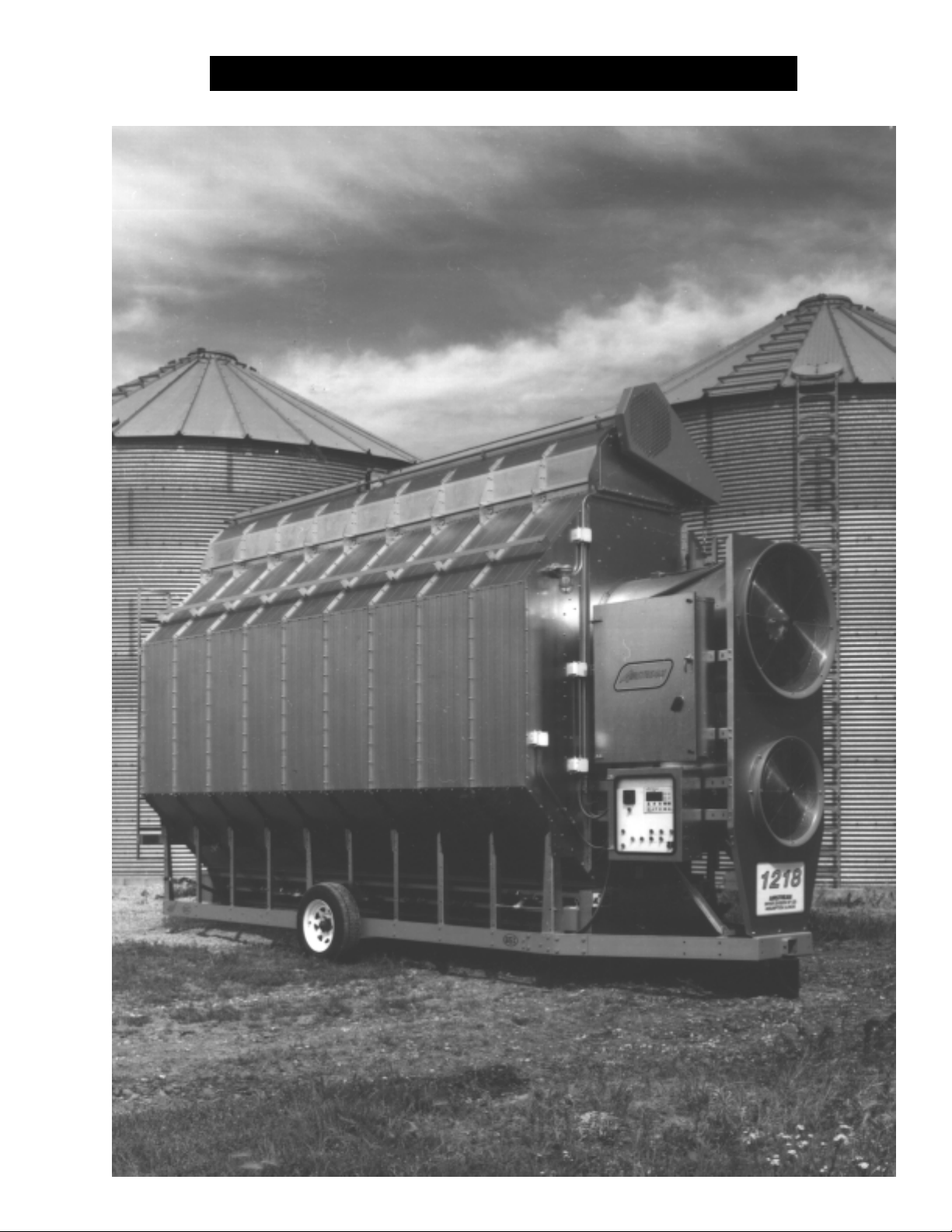
Thank you for choosing an Airstream
product. These products are the fin-
est built on the market today, and are
designed to give excellent perfor-
mance and service for many years.
Grain Systems, Inc. warrants its
products to be free of defects in ma-
terial and workmanship. The only
obligation of the manufacturer is to
repair or replace components which
have been submitted and found to
be defective within 24 months after
installation of the dryer, and within
12 months of a fan or heater pur-
chase. If so found to be defective,
the components will be repaired or
replaced without charge, this con-
stituting and entirely fulfilling the
warranty obligation. Grain Systems,
Inc. assumes no liability for ex-
penses incurred without written au-
This service school manual de-
scribes the operation and service for
all portable grain dryers, including
general grain drying information.
Dryer models are available
WARRANTYWARRANTY
WARRANTY
WARRANTYWARRANTY
thorizations; in no event shall liabil-
ity include special or consequen-
tial damages, or exceed the sell-
ing price of the product.
This warranty does not cover
products or parts which have been
damaged by negligent use, mis-
use, alteration or accident. Elec-
tric motors, tires, and other com-
ponents supplied by outside manu-
facturers have separate warran-
ties, from those suppliers. This
warranty is exclusive and in lieu of
all other warranties, expressed or
implied. Grain Systems, Inc. re-
serves the right to make design or
for liquid propane or natural gas fuel
supply, with either single phase 230
volt, or three phase 220 or 440 volt
electrical power (diesel and 380 volt
options also available).
specification changes at any time,
without any contingent obligations
to purchasers of products al-
ready sold.
All instructions shall be con-
strued as recommendation only.
Because of the many variable con-
ditions in actual installation, Grain
Systems, Inc. assumes no liability
for results arising from the use of
such recommendations. Any alter-
ation in design or operation of any
Grain Systems, Inc. product must
be submitted and approved in writ-
ing by Grain Systems, Inc. before
the alteration is made.
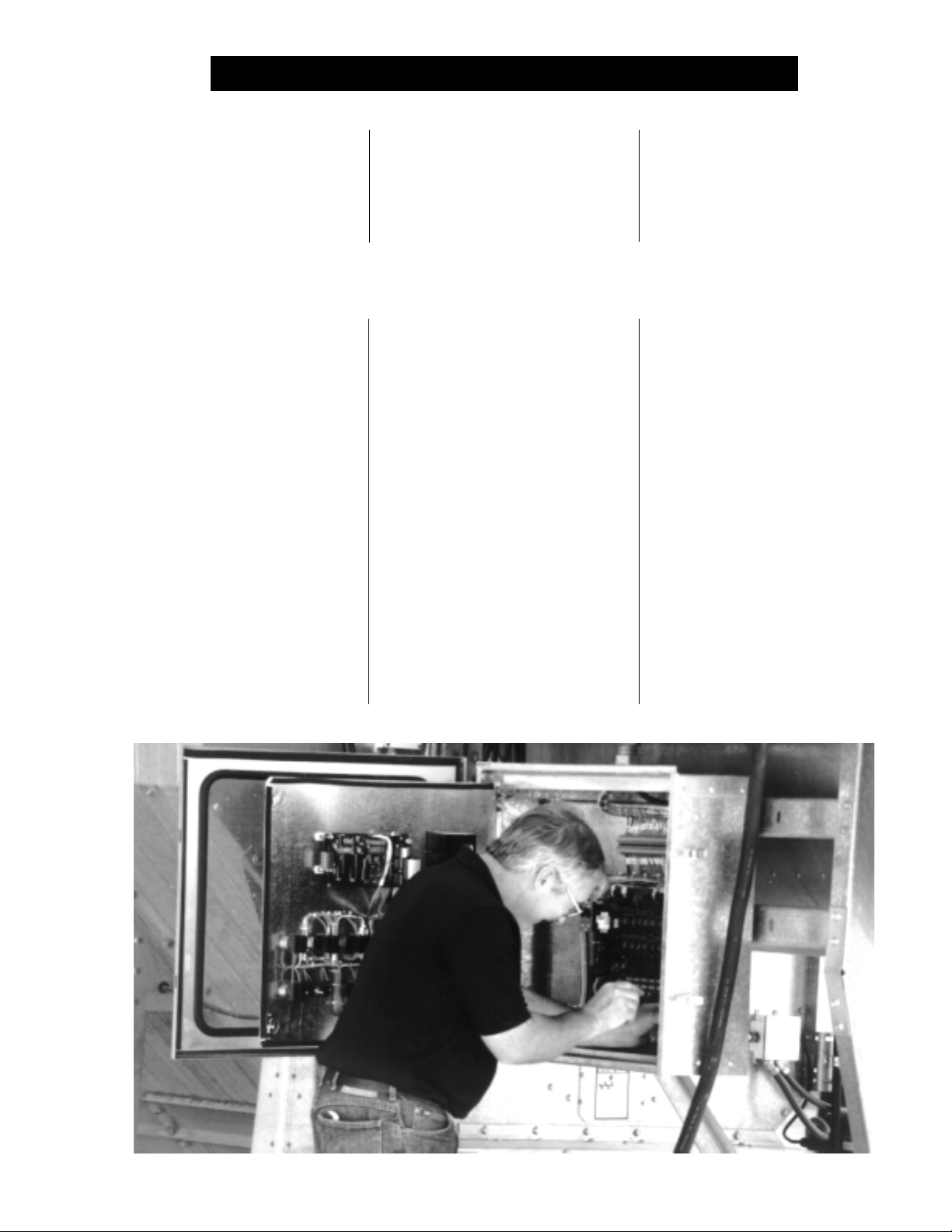
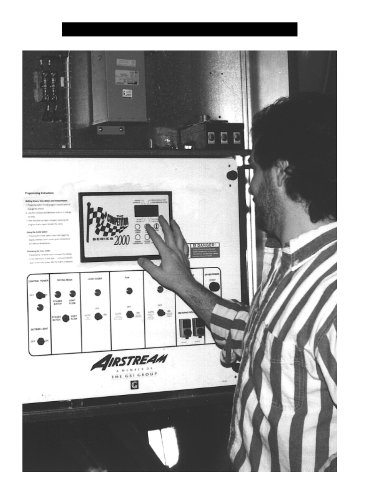
Airstream Service Technician checks the wiring on a single module grain dryer.Airstream Service Technician checks the wiring on a single module grain dryer.
Airstream Service Technician checks the wiring on a single module grain dryer.
Airstream Service Technician checks the wiring on a single module grain dryer.Airstream Service Technician checks the wiring on a single module grain dryer.
5
Page 6
SAFETY FIRSTSAFETY FIRST
SAFETY FIRST
SAFETY FIRSTSAFETY FIRST
Grain Systems, Inc.'s principle con-
cern is your safety and the safety of
others associated with grain han-
dling equipment. This manual was
written with that thought in mind. We
want to keep you as a customer.
This manual is to help you under-
The symbol shown below is used to
call your attention to instructions
concerning your personal safety.
Watch for this symbol; it points out
important safety precautions. It
means "ATTENTION", "WARNING",
"CAUTION", and "DANGER". Read
the message that follows and be
cautious to the possibility of per-
sonal injury or death.
stand safe operating proceedures
and some problems which may be
encountered by the operator and
other personnel.
As owner and/or operator, it is
your responsibility to know what re-
quirements, hazards and precau-
SAFETY ALERT SYMBOLSAFETY ALERT SYMBOL
SAFETY ALERT SYMBOL
SAFETY ALERT SYMBOLSAFETY ALERT SYMBOL
WARNING! BE ALERT!WARNING! BE ALERT!
WARNING! BE ALERT!
WARNING! BE ALERT!WARNING! BE ALERT!
Personnel operating or working around
grain drying equipment should read this
manual. This manual must be delivered
with equipment to its owner. Failure to
read this manual and its safety instruc-
tions is a misuse of the equipment.
tions exist, and to inform all person-
nel associated with the equipment
or who are in the area. Avoid any
alterations to the equipment. Such
alterations may produce a very dan-
gerous situation, where serious in-
jury or death may occur.
Grain Systems, Inc. recommends
that you contact your local power com-
pany and have a representative sur-
vey your equipment installation so
your wiring will be compatible with
their system and you will have ad-
equate power supplied to your unit.
6
SAFETY ALERT DECALSSAFETY ALERT DECALS
SAFETY ALERT DECALS
SAFETY ALERT DECALSSAFETY ALERT DECALS
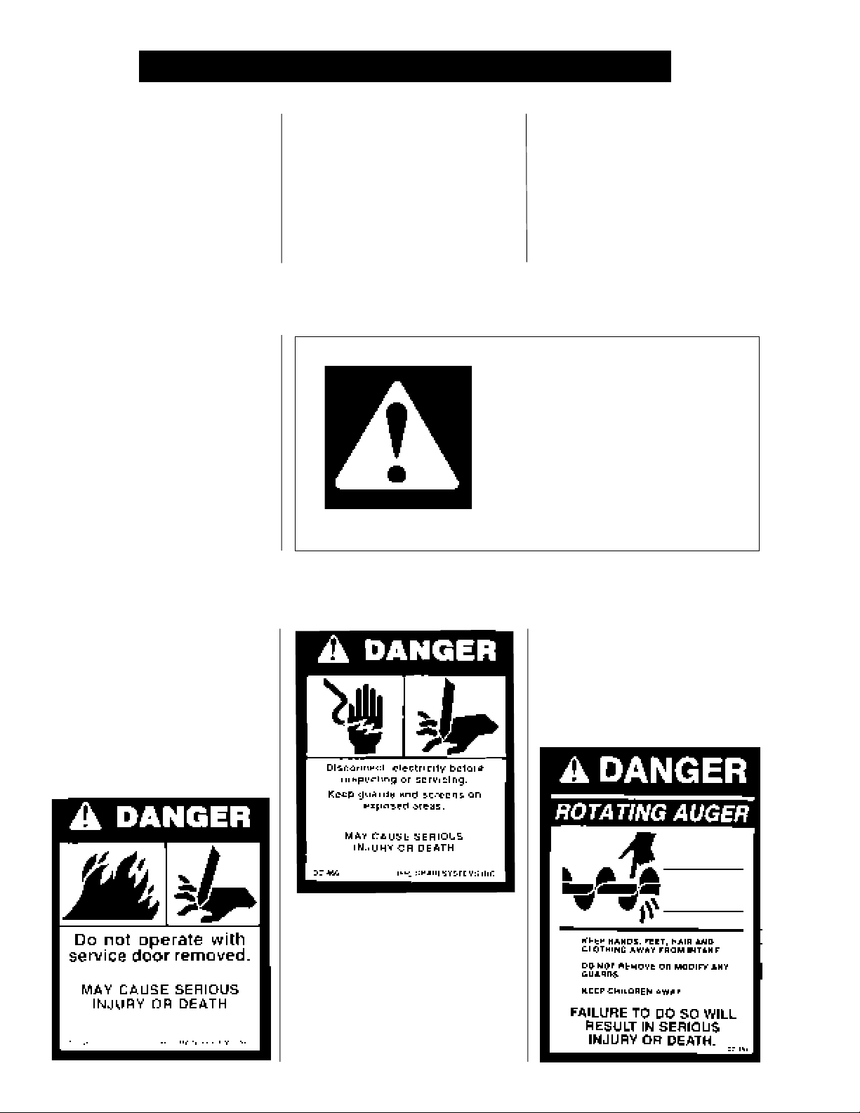
Safety decals should be read and
understood by all people in and
around the grain drying area. If the
following safety decals are not dis-
played on your dryer, or if they are
damaged, contact Grain Systems,
Inc. for replacement.
A CAREFUL OPERATORA CAREFUL OPERATOR
A CAREFUL OPERATOR
A CAREFUL OPERATORA CAREFUL OPERATOR
IS THE BEST INSURANCE IS THE BEST INSURANCE
IS THE BEST INSURANCE
IS THE BEST INSURANCE IS THE BEST INSURANCE
AGAINST AN ACCIDENTAGAINST AN ACCIDENT
AGAINST AN ACCIDENT
AGAINST AN ACCIDENTAGAINST AN ACCIDENT
Page 7
SAFETY ALERT DECALSSAFETY ALERT DECALS
SAFETY ALERT DECALS
SAFETY ALERT DECALSSAFETY ALERT DECALS
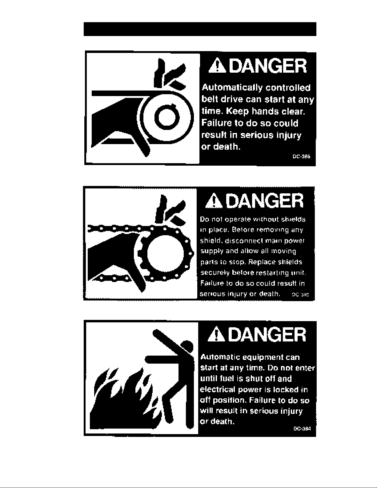
Three decals displayed on all Airstream Dryers. Belt drives, chain driven meter rollsThree decals displayed on all Airstream Dryers. Belt drives, chain driven meter rolls
Three decals displayed on all Airstream Dryers. Belt drives, chain driven meter rolls
Three decals displayed on all Airstream Dryers. Belt drives, chain driven meter rollsThree decals displayed on all Airstream Dryers. Belt drives, chain driven meter rolls
and combustible fuels must be treated with caution.and combustible fuels must be treated with caution.
and combustible fuels must be treated with caution.
and combustible fuels must be treated with caution.and combustible fuels must be treated with caution.
7
Page 8

SAFETY PRECAUTIONSSAFETY PRECAUTIONS
SAFETY PRECAUTIONS
SAFETY PRECAUTIONSSAFETY PRECAUTIONS
1. Read and understand the operating manual before trying to operate the
dryer, fan or heater.
2. Never operate a dryer while the
3. Power supply should be OFF for service of
Use CAUTION in checking voltage or other procedures requiring power
to be ON.
4. Check for gas leaks at all
detected, do not operate dryer. Shut down and repair before further
operation.
5. Never attempt to operate a dryer by jumping or otherwise bypassing
any safety devices on the unit.
6. Set
7. Keep the dryer clean. Do not allow fine material to accumulate in the
8.
pressure regulatorpressure regulator
pressure regulator to avoid excessive gas pressure applied to burner
pressure regulatorpressure regulator
during ignition and
ing procedures. Do not exceed maxi
perature.
num chambernum chamber
num chamber. Also occasionally clean the
num chambernum chamber
auger drive beltsauger drive belts
Keep
auger drive belts tight
auger drive beltsauger drive belts
when burner is in operation. See chart for operat-
guardsguards
guards are removed.
guardsguards
electrical componentselectrical components
electrical components.
electrical componentselectrical components
gas pipegas pipe
gas pipe connections. If any leaks are
gas pipegas pipe
mum recommended drying tem-
outside screensoutside screens
outside screens of the dryer.
outside screensoutside screens
enough to prevent slippage.
ple-ple-
ple-
ple-ple-
USE CAUTIONUSE CAUTION
USE CAUTION
USE CAUTIONUSE CAUTION
IN THE OPERATIONIN THE OPERATION
IN THE OPERATION
IN THE OPERATIONIN THE OPERATION
OF THIS EQUIPMENTOF THIS EQUIPMENT
OF THIS EQUIPMENT
OF THIS EQUIPMENTOF THIS EQUIPMENT
The design and manufacture of a
dryer is directed toward operator
safety. However, the very nature of
a grain dryer having a
high voltage
and high speed
present a hazard to personnel which
can not be completely safeguarded
against, without interfering with effi-
cient operation and reasonable ac-
cess to components.
Use extreme caution in working
around high speed
heaters, augers and auxiliary con-heaters, augers and auxiliary con-
heaters, augers and auxiliary con-
heaters, augers and auxiliary con-heaters, augers and auxiliary con-
veyorsveyors
veyors, which may start without
veyorsveyors
warning when the dryer is operating
on automatic control.
electrical equipmentelectrical equipment
electrical equipment
electrical equipmentelectrical equipment
rotating partsrotating parts
rotating parts, does
rotating partsrotating parts
gas burnergas burner
gas burner,
gas burnergas burner
fans, gas firedfans, gas fired
fans, gas fired
fans, gas firedfans, gas fired
KEEP THE DRYER CLEAN
DO NOT ALLOW FINE
9. Use CAUTION in working around high speed
and auxiliary conveyorsand auxiliary conveyors
and auxiliary conveyors which START AUTOMATICALLY.
and auxiliary conveyorsand auxiliary conveyors
10. Do not operate in any area where combustible material will be drawn into
fanfan
the
fan.
fanfan
11. Before attempting to remove and reinstall any
read the recommended procedure listed within the servicing section of
the manual.
12. Be certain that capacities of
augerauger
auger capacities.
augerauger
13. Clean grain is easier to dry. Fine material increases resistance to airflow
and requires removal of extra moisture.
READ THESE INSTRUCTIONSREAD THESE INSTRUCTIONS
READ THESE INSTRUCTIONS
READ THESE INSTRUCTIONSREAD THESE INSTRUCTIONS
BEFORE OPERATION AND SERVICEBEFORE OPERATION AND SERVICE
BEFORE OPERATION AND SERVICE
BEFORE OPERATION AND SERVICEBEFORE OPERATION AND SERVICE
SAVE FOR FUTURE REFERENCESAVE FOR FUTURE REFERENCE
SAVE FOR FUTURE REFERENCE
SAVE FOR FUTURE REFERENCESAVE FOR FUTURE REFERENCE
8
auxiliary conveyorsauxiliary conveyors
auxiliary conveyors are matched to dryer
auxiliary conveyorsauxiliary conveyors
fans, gas burners, augersfans, gas burners, augers
fans, gas burners, augers
fans, gas burners, augersfans, gas burners, augers
propellerpropeller
propeller, make certain to
propellerpropeller
MATERIAL TO ACCUMULATE
IN THE PLENUM CHAMBER
OR SURROUNDING THE
OUTSIDE OF THE DRYER
Continued safe, dependable opera-
tion of automatic equipment de-
pends, to a great degree, upon the
owner. For a safe and dependable
drying system, follow the recom-
mendations within this manual, and
make it a practice to regularly in-
spect the operation of the unit for any
developing problems or unsafe con-
ditions.
Take special note of the safety
precautions listed before attempting
to operate a dryer, fan or heater.
Page 9
C-SERIES DRYER CONTROL PANELC-SERIES DRYER CONTROL PANEL
C-SERIES DRYER CONTROL PANEL
C-SERIES DRYER CONTROL PANELC-SERIES DRYER CONTROL PANEL
9
Page 10
C-SERIES DRYER CONTROL PANELC-SERIES DRYER CONTROL PANEL
C-SERIES DRYER CONTROL PANEL
C-SERIES DRYER CONTROL PANELC-SERIES DRYER CONTROL PANEL
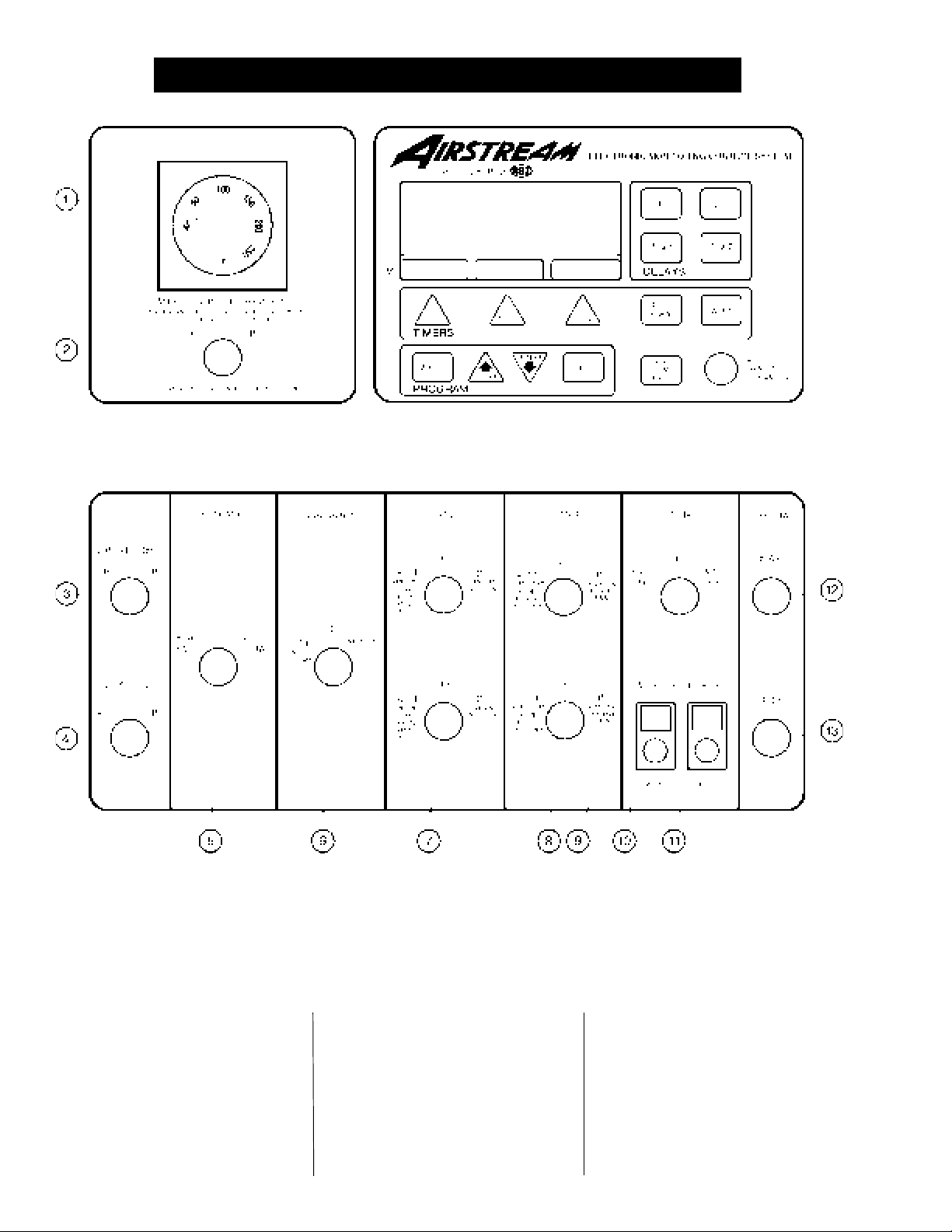
Figure 1: The C-Series grain dryer control panel with the Electronic Monitoring Control System in the upper right panel.Figure 1: The C-Series grain dryer control panel with the Electronic Monitoring Control System in the upper right panel.
Figure 1: The C-Series grain dryer control panel with the Electronic Monitoring Control System in the upper right panel.
Figure 1: The C-Series grain dryer control panel with the Electronic Monitoring Control System in the upper right panel.Figure 1: The C-Series grain dryer control panel with the Electronic Monitoring Control System in the upper right panel.
C-SERIES DRYER CONTROL PANEL FEATURINGC-SERIES DRYER CONTROL PANEL FEATURING
C-SERIES DRYER CONTROL PANEL FEATURING
C-SERIES DRYER CONTROL PANEL FEATURINGC-SERIES DRYER CONTROL PANEL FEATURING
THE ELECTRONIC MONITORING CONTROL SYSTEMTHE ELECTRONIC MONITORING CONTROL SYSTEM
THE ELECTRONIC MONITORING CONTROL SYSTEM
THE ELECTRONIC MONITORING CONTROL SYSTEMTHE ELECTRONIC MONITORING CONTROL SYSTEM
MOISTURE CONTROLMOISTURE CONTROL
MOISTURE CONTROL
control panel control panel
The
control panel provides easy
control panel control panel
access to gauges and controls, and
the ILLUMINATED SWITCHES pro-
vide a quick reference for every op-
erating function. The patent pend-
Electronic Monitoring ControlElectronic Monitoring Control
ing
Electronic Monitoring Control
Electronic Monitoring ControlElectronic Monitoring Control
SystemSystem
System is a computerized control
SystemSystem
10
system that gives instant information
regarding dryer operation.
MOISTURE CONTROLMOISTURE CONTROL
MOISTURE CONTROL
MOISTURE CONTROLMOISTURE CONTROL
THERMOSTAT(1)THERMOSTAT(1)
THERMOSTAT(1)
THERMOSTAT(1)THERMOSTAT(1)
This electronic
the moisture level of discharged grain
by sensing grain column temperature.
THERMOSTAT controls
MOISTURE CONTROLMOISTURE CONTROL
SWITCH(2)SWITCH(2)
SWITCH(2)
SWITCH(2)SWITCH(2)
This switch turns the power ON or
OFF to the MOISTURE CONTROL
THERMOSTAT. It lights up when
the grain column temperature is be-
low the thermostat set point.
Page 11

C-SERIES DRYER CONTROL PANELC-SERIES DRYER CONTROL PANEL
C-SERIES DRYER CONTROL PANEL
C-SERIES DRYER CONTROL PANELC-SERIES DRYER CONTROL PANEL
CONTROL POWERCONTROL POWER
CONTROL POWER
CONTROL POWERCONTROL POWER
SWITCH(3)SWITCH(3)
SWITCH(3)
SWITCH(3)SWITCH(3)
The power to the
toring Control Systemtoring Control System
toring Control System is turned
toring Control Systemtoring Control System
ON or OFF with this switch.
OUTSIDE LIGHT(4)OUTSIDE LIGHT(4)
OUTSIDE LIGHT(4)
OUTSIDE LIGHT(4)OUTSIDE LIGHT(4)
The dryer
or OFF here. It also may be set on
AUTO, which turns the light on while
the dryer is running and off if a shut-
down occurs.
DRYING MODE SWITCH(5)DRYING MODE SWITCH(5)
DRYING MODE SWITCH(5)
DRYING MODE SWITCH(5)DRYING MODE SWITCH(5)
This is used to select STAGED
BATCH or CONTINUOUS FLOW
drying. The switch will light only
after the
Control SystemControl System
Control System has been turned
Control SystemControl System
ON, the safety circuit is okay and
the RESET button on the control
panel has been pressed.
LOAD AUGER SWITCH(6)LOAD AUGER SWITCH(6)
LOAD AUGER SWITCH(6)
LOAD AUGER SWITCH(6)LOAD AUGER SWITCH(6)
This is used to select the operation
of the
and MANUAL position the
gerger
ger will operate if the dryer is low
gerger
on grain and will automatically shut
off when the dryer is full. In the
AUTO position only, the dryer will
shutdown after a preset period of
time set on the OUT OF GRAIN
TIMER, or if grain flow is interrupted
to the dryer. The switch will light
whenever the
ing.
to AUTO or MANUAL it also controls
the operation of any
equipmentequipment
equipment being utilized, such as
equipmentequipment
an
service lightservice light
service light is turned ON
service lightservice light
Electronic MonitoringElectronic Monitoring
Electronic Monitoring
Electronic MonitoringElectronic Monitoring
load augerload auger
load auger. In both the AUTO
load augerload auger
(Note: When this switch is set
auxiliary auger or conveyor.auxiliary auger or conveyor.
auxiliary auger or conveyor.
auxiliary auger or conveyor.auxiliary auger or conveyor.
Electronic Moni-Electronic Moni-
Electronic Moni-
Electronic Moni-Electronic Moni-
load au-load au-
load au-
load au-load au-
load augerload auger
load auger is operat-
load augerload auger
auxiliary loadauxiliary load
auxiliary load
auxiliary loadauxiliary load
FAN SWITCHES(7)FAN SWITCHES(7)
FAN SWITCHES(7)
FAN SWITCHES(7)FAN SWITCHES(7)
fanfan
Each
fan is turned ON or OFF with
fanfan
this switch. The ON position oper-
ates the
STAGED BATCH and CONTINU-
OUS FLOW modes. The AUTO po-
sition operates the
BATCH during the dry and cool
cycle. The switch will light up when-
ever the airflow switch is sensing
airflow and the dryer is full of grain.
This switch is used to turn the
burner burner
burner ON or OFF. The AUTO po-
burner burner
sition operates the
STAGED BATCH during the dry
cycle. The ON position will operate
the
ning. The switch will light up only when
the flame sensor detects the flame.
The UNLOAD switch turns the
tering rolls and discharge augertering rolls and discharge auger
tering rolls and discharge auger
tering rolls and discharge augertering rolls and discharge auger
ON or OFF, and selects the opera-
tion of the
• In the
MOISTURE CONTROL switch is
ON, and the DRYING MODE
switch is turned to CONTINUOUS
FLOW, the METERING ROLL
SPEED will alternate between the
HIGH speed metering roll potenti-
ometer setting and the LOW
speed metering roll potentiometer
setting depending on the control
signal from the MOISTURE CON-
TROL THERMOSTAT. The
charge augercharge auger
charge auger will operate con-
charge augercharge auger
tinuously.
fanfan
fan continuously during
fanfan
fan fan
fan in STAGED
fan fan
HEATER SWITCHES(8)HEATER SWITCHES(8)
HEATER SWITCHES(8)
HEATER SWITCHES(8)HEATER SWITCHES(8)
burnerburner
burner in
burnerburner
burnerburner
burner only when the
burnerburner
UNLOAD SWITCH(9)UNLOAD SWITCH(9)
UNLOAD SWITCH(9)
UNLOAD SWITCH(9)UNLOAD SWITCH(9)
metering rollsmetering rolls
metering rolls.
metering rollsmetering rolls
2 SPEED
position if the
fanfan
fan is run-
fanfan
me-me-
me-
me-me-
dis-dis-
dis-
dis-dis-
• In the 1 SPEED position, if the
MOISTURE CONTROL switch is
ON, and the DRYING MODE
switch is turned to CONTINUOUS
FLOW, the METERING ROLL
SPEED will operate at the HIGH
speed metering roll potentiometer
setting or turn OFF depending on
the control signal from the MOIS-
TURE CONTROL THERMOSTAT.
discharge augerdischarge auger
The
discharge auger will operate
discharge augerdischarge auger
whenever the
erating.
• In both the 1 SPEED or the 2
SPEED position, if the MOIS-
TURE CONTROL THERMOSTAT
is OFF, and the DRYING MODE
switch is turned to CONTINUOUS
FLOW, the METERING ROLL
SPEED can be manually con-
trolled by adjusting the HIGH
speed metering roll potentiometer.
discharge auger discharge auger
The
discharge auger will operate
discharge auger discharge auger
continuously.
• If the DRYING MODE switch is
turned to STAGED BATCH, the
UNLOAD switch should be set to
the 1 SPEED position. The
charge auger and meteringcharge auger and metering
charge auger and metering
charge auger and meteringcharge auger and metering
rollsrolls
rolls will only operate during
rollsrolls
the unload cycle of the staged
batch operation, and the ME-
TERING ROLL SPEED is ad-
justed using the HIGH speed
metering roll potentiometer.
Note: When this switch is set to
AUTO or MANUAL it also controls
the operation of any
equipmentequipment
equipment being utilized, such as
equipmentequipment
auxiliary auger or conveyorauxiliary auger or conveyor
an
auxiliary auger or conveyor.
auxiliary auger or conveyorauxiliary auger or conveyor
metering rolls metering rolls
metering rolls are op-
metering rolls metering rolls
dis-dis-
dis-
dis-dis-
auxiliary loadauxiliary load
auxiliary load
auxiliary loadauxiliary load
11
Page 12
C-SERIES DRYER CONTROL PANELC-SERIES DRYER CONTROL PANEL
C-SERIES DRYER CONTROL PANEL
C-SERIES DRYER CONTROL PANELC-SERIES DRYER CONTROL PANEL
LOW SPEED METERINGLOW SPEED METERING
LOW SPEED METERING
LOW SPEED METERINGLOW SPEED METERING
ROLL POTENTIOMETER(10)ROLL POTENTIOMETER(10)
ROLL POTENTIOMETER(10)
ROLL POTENTIOMETER(10)ROLL POTENTIOMETER(10)
This is used to adjust the LOW
speed of the
2 SPEED and MOISTURE CON-
TROL THERMOSTAT are in use.
HIGH SPEED METERINGHIGH SPEED METERING
HIGH SPEED METERING
HIGH SPEED METERINGHIGH SPEED METERING
ROLL POTENTIOMETER(11)ROLL POTENTIOMETER(11)
ROLL POTENTIOMETER(11)
ROLL POTENTIOMETER(11)ROLL POTENTIOMETER(11)
This is used to:
• Set the HIGH speed of the
ing rolling roll
ing roll when the 2 SPEED auto-
ing rolling roll
matic moisture control feature of the
dryer is utilized.
• Set the speed of the
when the 1 SPEED automatic
metering rollmetering roll
metering roll when the
metering rollmetering roll
meter-meter-
meter-
meter-meter-
metering rollsmetering rolls
metering rolls
metering rollsmetering rolls
moisture control feature of the
dryer is utilized.
• Set the speed of the
rolls rolls
rolls during continuous flow op-
rolls rolls
eration when the moisture control
is not used.
• Set the rate of grain discharge from
the dryer during the unload cycle of
staged batch dryer operation.
DRYER POWERDRYER POWER
DRYER POWER
DRYER POWERDRYER POWER
START SWITCH(12)START SWITCH(12)
START SWITCH(12)
START SWITCH(12)START SWITCH(12)
This switch starts and operates the
dryer based on switch settings. If
other switch settings are in the OFF
position, individual dryer compo-
meteringmetering
metering
meteringmetering
nents can be operated by turning the
DRYING MODE switch to CON-
TINUOUS FLOW, pressing the
DRYER POWER START button and
then turning ON the desired dryer
component.
DRYER POWERDRYER POWER
DRYER POWER
DRYER POWERDRYER POWER
STOP SWITCH(13)STOP SWITCH(13)
STOP SWITCH(13)
STOP SWITCH(13)STOP SWITCH(13)
This switch stops all dryer func-
tions. If an automatic dryer shut-
down occurs, first determine and
correct the cause of the shutdown.
Then, press the DRYER POWER
STOP button to reset the dryer be-
fore restarting.
12
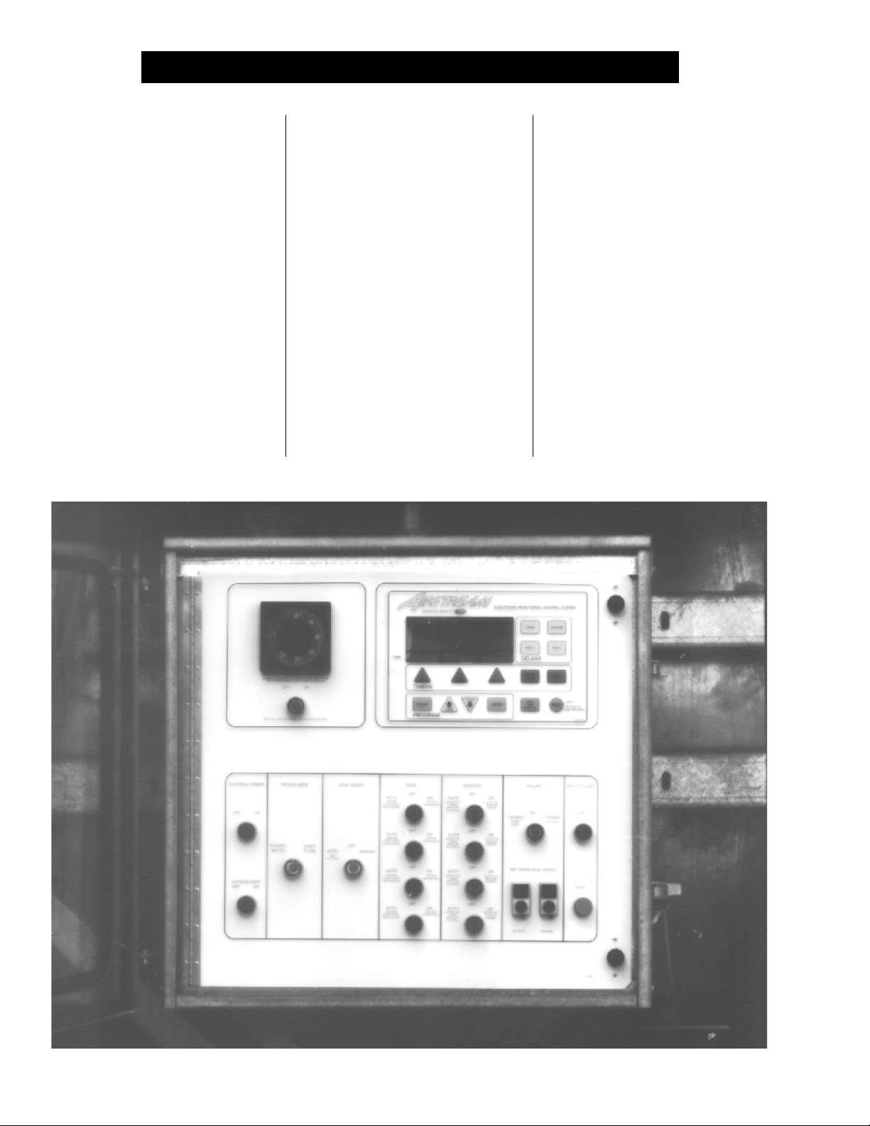
An Airstream C-Series Dryer Control Panel (four fan model) mounted on the dryer.An Airstream C-Series Dryer Control Panel (four fan model) mounted on the dryer.
An Airstream C-Series Dryer Control Panel (four fan model) mounted on the dryer.
An Airstream C-Series Dryer Control Panel (four fan model) mounted on the dryer.An Airstream C-Series Dryer Control Panel (four fan model) mounted on the dryer.
Page 13
C-SERIES DRYER CONTROL PANELC-SERIES DRYER CONTROL PANEL
C-SERIES DRYER CONTROL PANEL
C-SERIES DRYER CONTROL PANELC-SERIES DRYER CONTROL PANEL
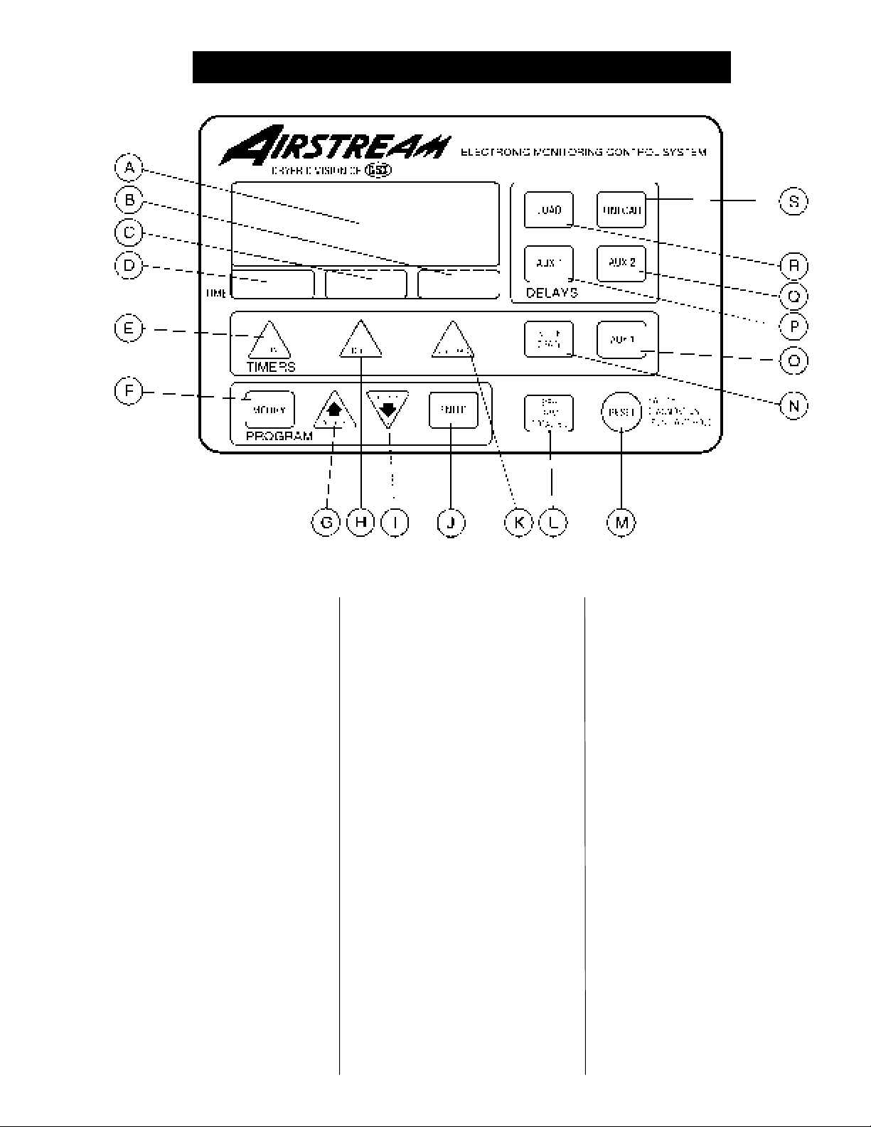
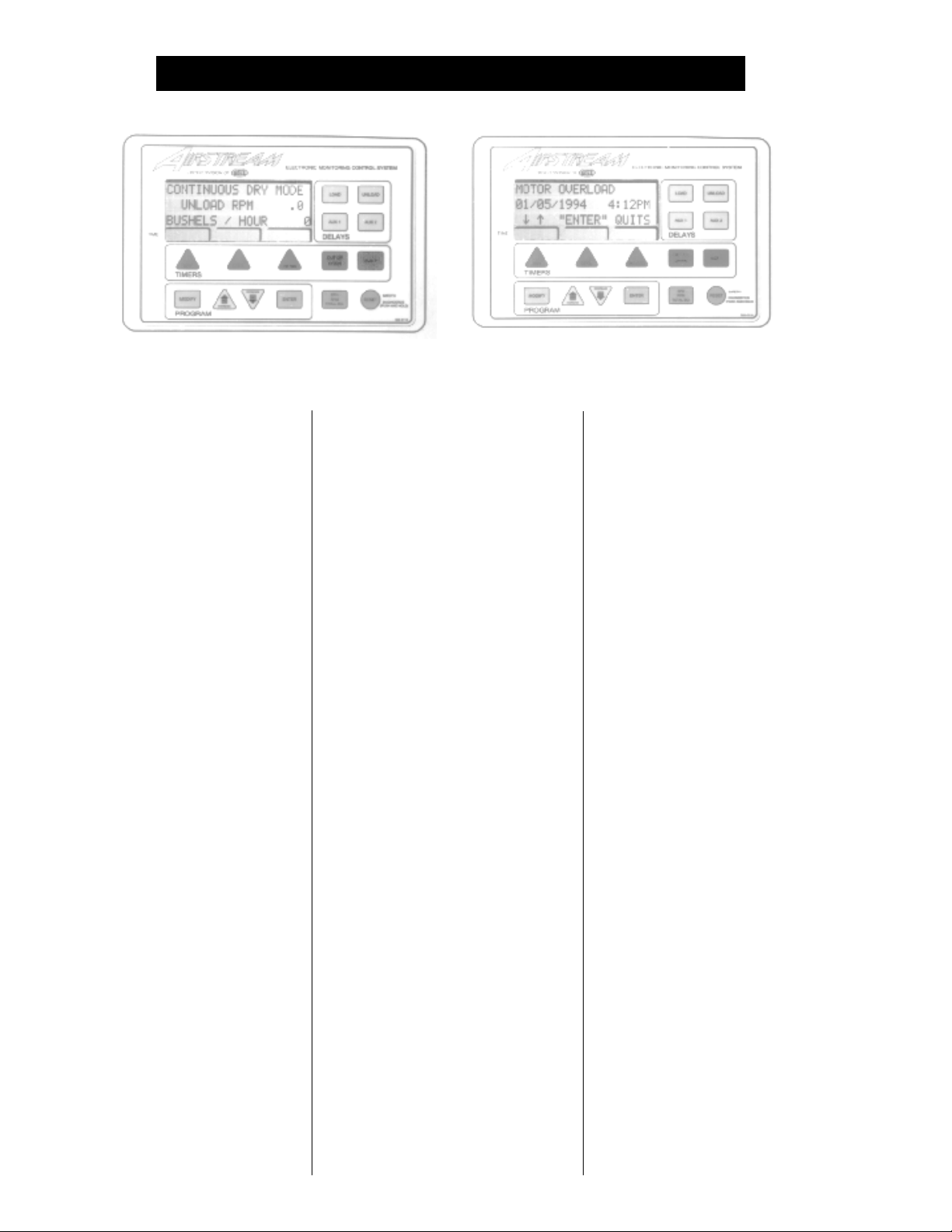
Figure 2: The C-Series Airstream Electronic Monitoring Control System.Figure 2: The C-Series Airstream Electronic Monitoring Control System.
Figure 2: The C-Series Airstream Electronic Monitoring Control System.
Figure 2: The C-Series Airstream Electronic Monitoring Control System.Figure 2: The C-Series Airstream Electronic Monitoring Control System.
ELECTRONICELECTRONIC
ELECTRONIC
ELECTRONICELECTRONIC
MONITORING CONTROLMONITORING CONTROL
MONITORING CONTROL
MONITORING CONTROLMONITORING CONTROL
SYSTEMSYSTEM
SYSTEM
SYSTEMSYSTEM
Electronic Monitoring ControlElectronic Monitoring Control
The
Electronic Monitoring Control
Electronic Monitoring ControlElectronic Monitoring Control
SystemSystem
System (fig. 2) controls all timing
SystemSystem
functions and safety circuit checks.
It is designed to simplify dryer op-
eration by providing printed mes-
sages and warnings on its liquid
crystal display (LCD).
TURNING ON THETURNING ON THE
TURNING ON THE
TURNING ON THETURNING ON THE
ELECTRONICELECTRONIC
ELECTRONIC
ELECTRONICELECTRONIC
MONITORING CONTROLMONITORING CONTROL
MONITORING CONTROL
MONITORING CONTROLMONITORING CONTROL
SYSTEMSYSTEM
SYSTEM
SYSTEMSYSTEM
Turn the CONTROL POWER switch
to ON. The monitor will display a
copyright message and model num-
ber, total running time in hours and
minutes and the current time and
date (fig. 2-A). To activate the control-
ler press the RESET button (fig. 2-M).
SETTING THE DRY, COOL,SETTING THE DRY, COOL,
SETTING THE DRY, COOL,
SETTING THE DRY, COOL,SETTING THE DRY, COOL,
UNLOAD AND BATCHUNLOAD AND BATCH
UNLOAD AND BATCH
UNLOAD AND BATCHUNLOAD AND BATCH
TIMERSTIMERS
TIMERS
TIMERSTIMERS
The DRY, COOL and UNLOAD tim-
ers (fig. 2-E, H, K) are used to set
the cycle times in the STAGED
BATCH DRYING MODE only. To
use and display the settings on
these three TIMERS, the DRYING
MODE switch (fig. 1-6) must be in
the STAGED BATCH position. The
current setting on these three TIM-
ERS is displayed directly above
each TIMER button (fig. 2-B, C, D).
To change the setting of these TIM-
ERS follow these instructions:
1. Press the DRY, COOL or UN-
LOAD TIMER button (fig. 2-E,
H, K).
2. Press the MODIFY button (fig.
2-F).
3. Press the INCREASE or DE-
CREASE (fig. 2-G, I) button to
adjust the settings.
4. Press the ENTER button to en-
ter new setting into the control-
ler (fig. 2-J).
After the DRY, COOL or UNLOAD
button is pressed, screen messages
on the LCD display of the
Monitoring Control SystemMonitoring Control System
Monitoring Control System direct
Monitoring Control SystemMonitoring Control System
the dryer operation through the proper
sequence for setting the TIMERS.
During operation the remaining time
on each TIMER is displayed. If the
power goes out or if the dryer is
stopped, these times are saved by the
controller. When the dryer is restarted
the TIMERS will continue timing
down from these times. They will
return to their initial setting if the
RESET button (fig. 2, M) is pushed.
ElectronicElectronic
Electronic
ElectronicElectronic
13
Page 14
C-SERIES DRYER CONTROL PANELC-SERIES DRYER CONTROL PANEL
C-SERIES DRYER CONTROL PANEL
C-SERIES DRYER CONTROL PANELC-SERIES DRYER CONTROL PANEL
The Airstream Electronic Monitoring Control System showing several different LCD displays.The Airstream Electronic Monitoring Control System showing several different LCD displays.
The Airstream Electronic Monitoring Control System showing several different LCD displays.
The Airstream Electronic Monitoring Control System showing several different LCD displays.The Airstream Electronic Monitoring Control System showing several different LCD displays.
SETTING THE OUT OFSETTING THE OUT OF
SETTING THE OUT OF
SETTING THE OUT OFSETTING THE OUT OF
GRAIN TIMERGRAIN TIMER
GRAIN TIMER
GRAIN TIMERGRAIN TIMER
If the dryer runs out of grain while
the LOAD AUGER switch (fig. 1-7)
is in the AUTO position, the OUT OF
GRAIN timer (fig. 2-N) automatically
shuts OFF the dryer after the period
of time preset on the TIMER. When
pressed, the display will show the
amount of time left on the TIMER
and the percentage of time used by
the last load. A second screen will
appear with the TIMER'S setting,
and may be modified as described
in the BATCH TIMER section.
SETTING THE LOAD ANDSETTING THE LOAD AND
SETTING THE LOAD AND
SETTING THE LOAD ANDSETTING THE LOAD AND
UNLOAD DELAYSUNLOAD DELAYS
UNLOAD DELAYS
UNLOAD DELAYSUNLOAD DELAYS
Electronic Monitoring ControlElectronic Monitoring Control
The
Electronic Monitoring Control
Electronic Monitoring ControlElectronic Monitoring Control
System System
System has four built in TIMER de-
System System
lays. The LOAD DELAY (fig. 2-R) is
used to delay the starting of the
augerauger
auger when the dryer is unloading
augerauger
to prevent the
ing and stopping. The UNLOAD
DELAY (fig. 2-S) is used to control
the amount of time the
gerger
ger runs after the
gerger
stop to allow for
Both the LOAD and UNLOAD DE-
LAYS are set using the same pro-
load augerload auger
load auger from start-
load augerload auger
metering rollsmetering rolls
metering rolls
metering rollsmetering rolls
auger auger
auger cleanout.
auger auger
loadload
load
loadload
unload au-unload au-
unload au-
unload au-unload au-
cedure as the TIMERS. The AUX 1
(fig.2-P) and AUX 2 (fig. 2-Q) DE-
LAYS are presently not being used.
UTILIZING THEUTILIZING THE
UTILIZING THE
UTILIZING THEUTILIZING THE
BUSHEL COUNTERBUSHEL COUNTER
BUSHEL COUNTER
BUSHEL COUNTERBUSHEL COUNTER
When the dryer is operating, the
LCD display (fig. 2-A) shows the
DRYER MODE OF OPERATION on
the first line, the BUSHELS PER
HOUR or the METERING ROLL
RPM on the second line and the
TOTAL BUSHELS DRIED on the
third line. By pressing the BPH/
RPM/TOTAL BU button (fig. 2-L) the
second line will alternate between
the METERING ROLL RPM's or the
BUSHEL PER HOUR rate that the
metering rollsmetering rolls
metering rolls are removing grain
metering rollsmetering rolls
from the dryer. The TOTAL BUSH-
ELS DRIED reading is the total since
the bushel counter was last reset.
To reset the BUSHEL COUNTER,
press and hold the RESET button
(fig. 2-M) for five seconds. Press the
ENTER button (fig. 2-J) through the
date and time settings, and follow
the instructions displayed on the
LCD for resetting the counter.
In the BATCH MODE, the first
line of the LCD display tells which
TIMER is being used, and the sec-
ond line switches between TOTAL
BATCHES, UNLOAD RPM or TOTAL
BUSHELS. The third line indicates
TOTAL DRY TIME, and the fourth line
is TIME REMAINING on the TIMERS.
DRYER SAFETY CIRCUITDRYER SAFETY CIRCUIT
DRYER SAFETY CIRCUIT
DRYER SAFETY CIRCUITDRYER SAFETY CIRCUIT
Electronic Monitoring ControlElectronic Monitoring Control
The
Electronic Monitoring Control
Electronic Monitoring ControlElectronic Monitoring Control
System System
System continuously checks all
System System
safety circuits on the dryer, and will
automatically shut the dryer down
should a problem occur. The cause
of the dryer shutdown will be dis-
played on the LCD display (fig. 2-
A), and a beeper will sound on the
controller. To restart the dryer after
a safety shutdown, first correct the
reason for the shutdown, and then
press the DRYER POWER STOP
(FIG. 1-14) button to reset the circuit.
Press the START button (fig. 1-13).
Electronic Monitoring Electronic Monitoring
The
Electronic Monitoring
Electronic Monitoring Electronic Monitoring
Control System Control System
Control System stores in its
Control System Control System
memory the time, date and cause for
the last 25 dryer safety shutdowns.
To review this information, hold the
RESET button in for five seconds.
The procedure for reviewing the
safety circuit shutdown log will be
displayed on the LCD display.
14
Page 15

C-SERIES DRYER CONTROL PANELC-SERIES DRYER CONTROL PANEL
C-SERIES DRYER CONTROL PANEL
C-SERIES DRYER CONTROL PANELC-SERIES DRYER CONTROL PANEL
SAFETY CIRCUIT SHUTDOWN MESSAGESSAFETY CIRCUIT SHUTDOWN MESSAGES
SAFETY CIRCUIT SHUTDOWN MESSAGES
SAFETY CIRCUIT SHUTDOWN MESSAGESSAFETY CIRCUIT SHUTDOWN MESSAGES
BURNER VAPOR HIGHBURNER VAPOR HIGH
BURNER VAPOR HIGH
BURNER VAPOR HIGHBURNER VAPOR HIGH
TEMPERATURETEMPERATURE
TEMPERATURE
TEMPERATURETEMPERATURE
The LP gas vapor
sorsor
sor located in the
sorsor
downstream from the vaporizer, has
opened indicating that the vaporizer
is running too hot and must be read-
justed. This sensor is set at 200°F
and automatically resets itself when
cool. The message will distinguish
between burners.
BURNER WARNING FLAMEBURNER WARNING FLAME
BURNER WARNING FLAME
BURNER WARNING FLAMEBURNER WARNING FLAME
NOT DETECTEDNOT DETECTED
NOT DETECTED
NOT DETECTEDNOT DETECTED
flame sensorflame sensor
The
flame sensor has failed to de-
flame sensorflame sensor
tect a burner flame indicating that the
burner has failed to light. There is a
problem with the flame sensing cir-
cuitry or the dryer is not getting
burner fuel. The message will dis-
tinguish between burners.
FAN HOUSING HIGHFAN HOUSING HIGH
FAN HOUSING HIGH
FAN HOUSING HIGHFAN HOUSING HIGH
TEMPERATURETEMPERATURE
TEMPERATURE
TEMPERATURETEMPERATURE
temperature high limittemperature high limit
The
temperature high limit located
temperature high limittemperature high limit
on the
opened, indicating an over tempera-
ture condition has occurred towards
the rear of the
This control is set at 200°F and must
be manually reset. The message will
distinguish between fans.
The contacts in the
opened due to insufficient airflow for
the
will distinguish between burners.
The
has opened, indicating that grain is
backing up into the
fan/burner housingfan/burner housing
fan/burner housing has
fan/burner housingfan/burner housing
BURNER SHUTDOWNBURNER SHUTDOWN
BURNER SHUTDOWN
BURNER SHUTDOWNBURNER SHUTDOWN
LOSS OF AIRFLOWLOSS OF AIRFLOW
LOSS OF AIRFLOW
LOSS OF AIRFLOWLOSS OF AIRFLOW
burnerburner
burner to operate. The message
burnerburner
GRAIN DISCHARGEGRAIN DISCHARGE
GRAIN DISCHARGE
GRAIN DISCHARGEGRAIN DISCHARGE
WARNINGWARNING
WARNING
WARNINGWARNING
lid on the grain discharge box lid on the grain discharge box
lid on the grain discharge box
lid on the grain discharge box lid on the grain discharge box
temperature sen-temperature sen-
temperature sen-
temperature sen-temperature sen-
gas pipe traingas pipe train
gas pipe train
gas pipe traingas pipe train
fan/heater housingfan/heater housing
fan/heater housing.
fan/heater housingfan/heater housing
air switchair switch
air switch have
air switchair switch
discharge boxdischarge box
discharge box.
discharge boxdischarge box
LOWER ADJUSTABLELOWER ADJUSTABLE
LOWER ADJUSTABLE
LOWER ADJUSTABLELOWER ADJUSTABLE
GRAIN HIGHGRAIN HIGH
GRAIN HIGH
GRAIN HIGHGRAIN HIGH
TEMPERATURETEMPERATURE
TEMPERATURE
TEMPERATURETEMPERATURE
An over temperature condition has oc-
curred in the
as viewed from behind the dryer)
grain column grain column
grain column causing the control to
grain column grain column
shut down the dryer. This control is
adjustable from 80° to 220°F, and au-
tomatically resets itself when cool.
LOWER FIXED GRAINLOWER FIXED GRAIN
LOWER FIXED GRAIN
LOWER FIXED GRAINLOWER FIXED GRAIN
HIGH TEMPERATUREHIGH TEMPERATURE
HIGH TEMPERATURE
HIGH TEMPERATUREHIGH TEMPERATURE
An over temperature condition has oc-
curred in the
viewed from behind the dryer)
umn umn
umn causing the control to shutdown
umn umn
the dryer. This control is set at 210°F
and automatically resets itself when cool.
MOTOR OVERLOADMOTOR OVERLOAD
MOTOR OVERLOAD
MOTOR OVERLOADMOTOR OVERLOAD
One of the
either the
iliary motorsiliary motors
iliary motors has opened, indicat-
iliary motorsiliary motors
ing an overcurrent condition. The
overloadsoverloads
overloads must be manually reset.
overloadsoverloads
OUT OF GRAIN WARNING/OUT OF GRAIN WARNING/
OUT OF GRAIN WARNING/
OUT OF GRAIN WARNING/OUT OF GRAIN WARNING/
UNLOAD CLEANOUTUNLOAD CLEANOUT
UNLOAD CLEANOUT
UNLOAD CLEANOUTUNLOAD CLEANOUT
The dryer has run low on grain, and
the OUT OF GRAIN TIMER has
timed out, shutting the dryer down.
unload augerunload auger
The
unload auger will clean out the
unload augerunload auger
dryer if it is in continuous flow op-
eration with the unload switch on.
SUPPLY WARNINGSUPPLY WARNING
SUPPLY WARNING
SUPPLY WARNINGSUPPLY WARNING
right circuit breakerright circuit breaker
The
right circuit breaker on the
right circuit breakerright circuit breaker
put/output boardput/output board
put/output board has tripped.
put/output boardput/output board
L1 VOLTAGE LOSTL1 VOLTAGE LOST
L1 VOLTAGE LOST
L1 VOLTAGE LOSTL1 VOLTAGE LOST
left circuit breakerleft circuit breaker
The
left circuit breaker located on
left circuit breakerleft circuit breaker
input/output board input/output board
the
input/output board of the
input/output board input/output board
tronic Monitoring Control Systemtronic Monitoring Control System
tronic Monitoring Control System
tronic Monitoring Control Systemtronic Monitoring Control System
has tripped, or one of the hardware
timers has shut down the dryer.
right sideright side
right side (left and right
right sideright side
left side left side
left side (left and right as
left side left side
grain col- grain col-
grain col-
grain col- grain col-
thermal overloadsthermal overloads
thermal overloads on
thermal overloadsthermal overloads
fan, load, unload fan, load, unload
fan, load, unload or
fan, load, unload fan, load, unload
12 VOLT POWER12 VOLT POWER
12 VOLT POWER
12 VOLT POWER12 VOLT POWER
aux-aux-
aux-
aux-aux-
in-in-
in-
in-in-
Elec-Elec-
Elec-
Elec-Elec-
METERING ROLL DRIVEMETERING ROLL DRIVE
METERING ROLL DRIVE
METERING ROLL DRIVEMETERING ROLL DRIVE
SYSTEM FAILURESYSTEM FAILURE
SYSTEM FAILURE
SYSTEM FAILURESYSTEM FAILURE
metering roll drive metering roll drive
The
metering roll drive
metering roll drive metering roll drive
failed to turn. A broken chain or jammed
metering roll is a possible cause.
RIGHT METERING ROLLRIGHT METERING ROLL
RIGHT METERING ROLL
RIGHT METERING ROLLRIGHT METERING ROLL
FAILUREFAILURE
FAILURE
FAILUREFAILURE
right right
The
right (as viewed from behind the
right right
metering roll metering roll
dryer)
metering roll has stopped turn-
metering roll metering roll
ing, or the sensor has been damaged.
LEFT METERING ROLLLEFT METERING ROLL
LEFT METERING ROLL
LEFT METERING ROLLLEFT METERING ROLL
FAILUREFAILURE
FAILURE
FAILUREFAILURE
left left
The
left (as viewed from behind the
left left
metering rollmetering roll
dryer)
metering roll has stopped turn-
metering rollmetering roll
ing, or the sensor has been damaged.
PLENUM HIGHPLENUM HIGH
PLENUM HIGH
PLENUM HIGHPLENUM HIGH
TEMPERATURETEMPERATURE
TEMPERATURE
TEMPERATURETEMPERATURE
An over temperature condition has
occurred inside the
This control is a 300°F limit and au-
tomatically resets itself when cool.
The message will distinguish be-
tween plenums.
AUXILIARY SAFETYAUXILIARY SAFETY
AUXILIARY SAFETY
AUXILIARY SAFETYAUXILIARY SAFETY
SHUTDOWNSHUTDOWN
SHUTDOWN
SHUTDOWNSHUTDOWN
A shutdown has occurred due to an
auxiliary installed safety feature.
FAN FAILURE NO AIRFLOWFAN FAILURE NO AIRFLOW
FAN FAILURE NO AIRFLOW
FAN FAILURE NO AIRFLOWFAN FAILURE NO AIRFLOW
air switchair switch
The
air switch contacts have opened.
air switchair switch
fanfan
The
fan may not be turning, or the
fanfan
switchswitch
switch may need adjustment. The mes-
switchswitch
sage will distinguish between fans.
FAN CANNOT FAN CANNOT
FAN CANNOT
FAN CANNOT FAN CANNOT
CHECK AIR SWITCHCHECK AIR SWITCH
CHECK AIR SWITCH
CHECK AIR SWITCHCHECK AIR SWITCH
air switchair switch
The
air switch contacts have closed
air switchair switch
prior to the
freewheeling
ting of the
will distinguish between fans.
fan fan
fan starting, indicating a
fan fan
bladeblade
blade or improper set-
bladeblade
air switchair switch
air switch. The message
air switchair switch
systemsystem
system has
systemsystem
dryer plenumdryer plenum
dryer plenum.
dryer plenumdryer plenum
airair
air
airair
STARTSTART
START
STARTSTART
15
Page 16
SERIES 2000 DRYER CONTROL PANELSERIES 2000 DRYER CONTROL PANEL
SERIES 2000 DRYER CONTROL PANEL
SERIES 2000 DRYER CONTROL PANELSERIES 2000 DRYER CONTROL PANEL
16
Page 17
SERIES 2000 DRYER CONTROL PANELSERIES 2000 DRYER CONTROL PANEL
SERIES 2000 DRYER CONTROL PANEL
SERIES 2000 DRYER CONTROL PANELSERIES 2000 DRYER CONTROL PANEL
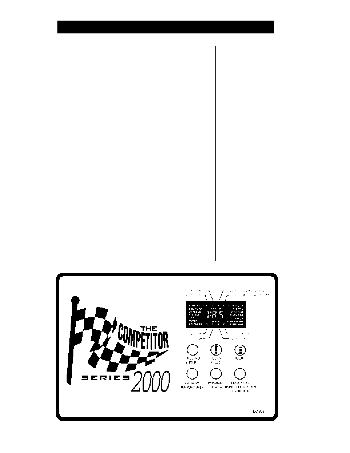
DRYER CONTROL PANEL FEATURING THE COMPETITORDRYER CONTROL PANEL FEATURING THE COMPETITOR
DRYER CONTROL PANEL FEATURING THE COMPETITOR
DRYER CONTROL PANEL FEATURING THE COMPETITORDRYER CONTROL PANEL FEATURING THE COMPETITOR
SERIES 2000 CONTROL SYSTEMSERIES 2000 CONTROL SYSTEM
SERIES 2000 CONTROL SYSTEM
SERIES 2000 CONTROL SYSTEMSERIES 2000 CONTROL SYSTEM
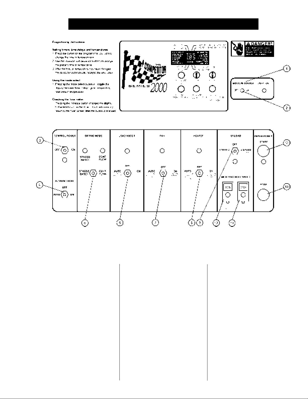
control panelcontrol panel
The
control panel provides easy
control panelcontrol panel
access to gauges and controls. The
Competitor Series 2000 Control
System is a computerized control
system that gives instant information
regarding dryer operation.
MOISTURE CONTROL(1)MOISTURE CONTROL(1)
MOISTURE CONTROL(1)
MOISTURE CONTROL(1)MOISTURE CONTROL(1)
The Series 2000 Dryer has a built in
moisture control. It controls the
moisture level of discharged grain
by sensing grain column temperature.
MOISTURE CONTROLMOISTURE CONTROL
MOISTURE CONTROL
MOISTURE CONTROLMOISTURE CONTROL
SWITCH(2)SWITCH(2)
SWITCH(2)
SWITCH(2)SWITCH(2)
This switch turns the power ON or
Figure 3: The grain dryer control panel.Figure 3: The grain dryer control panel.
Figure 3: The grain dryer control panel.
Figure 3: The grain dryer control panel.Figure 3: The grain dryer control panel.
OFF to the moisture control. The light
beside the switch is illuminated when
the grain column temperature is be-
low the moisture control set point.
CONTROL POWERCONTROL POWER
CONTROL POWER
CONTROL POWERCONTROL POWER
SWITCH(3)SWITCH(3)
SWITCH(3)
SWITCH(3)SWITCH(3)
The power to the Competitor 2000
Control System is turned on or off
with this switch.
OUTSIDE LIGHT(4)OUTSIDE LIGHT(4)
OUTSIDE LIGHT(4)
OUTSIDE LIGHT(4)OUTSIDE LIGHT(4)
The dryer outside light is turned on
or off here. In auto the light turns
off if the dryer has a shutdown.
DRYING MODE SWITCH(5)DRYING MODE SWITCH(5)
DRYING MODE SWITCH(5)
DRYING MODE SWITCH(5)DRYING MODE SWITCH(5)
This is used to select staged batch
or continuous flow drying.
LOAD AUGER SWITCH(6)LOAD AUGER SWITCH(6)
LOAD AUGER SWITCH(6)
LOAD AUGER SWITCH(6)LOAD AUGER SWITCH(6)
This is used to select the opera-
tion of the
AUTO and MANUAL position the
load auger load auger
load auger will operate if the dryer
load auger load auger
is low on grain and will automati-
cally shut off when the dryer is full.
In the AUTO position only, the
dryer will shut down after a preset
period of time set on the OUT OF
GRAIN TIMER.
load augerload auger
load auger. In both the
load augerload auger
17
Page 18

SERIES 2000 DRYER CONTROL PANELSERIES 2000 DRYER CONTROL PANEL
SERIES 2000 DRYER CONTROL PANEL
SERIES 2000 DRYER CONTROL PANELSERIES 2000 DRYER CONTROL PANEL
Note: When this switch is set to
AUTO or MANUAL it also controls
the operation of any
equipmentequipment
equipment being utilized, such as
equipmentequipment
auxiliary auger or conveyorauxiliary auger or conveyor
an
auxiliary auger or conveyor.
auxiliary auger or conveyorauxiliary auger or conveyor
FAN SWITCH(7)FAN SWITCH(7)
FAN SWITCH(7)
FAN SWITCH(7)FAN SWITCH(7)
fanfan
The
fan is turned ON or OFF with this
fanfan
switch. The ON position operates the
fan fan
fan continuously during STAGED
fan fan
BATCH and CONTINUOUS FLOW
modes. The AUTO position operates
fan fan
the
fan in STAGED BATCH during the
fan fan
dry and cool cycle. The light comes
on only when air pressure is sensed.
HEATER SWITCH(8)HEATER SWITCH(8)
HEATER SWITCH(8)
HEATER SWITCH(8)HEATER SWITCH(8)
This switch is used to turn the
ON or OFF. The AUTO position op-
erates the
during the dry cycle. The ON posi-
tion will operate the
the
comes on only when flame is detected.
The UNLOAD switch turns the
tering rolls and discharge augertering rolls and discharge auger
tering rolls and discharge auger
tering rolls and discharge augertering rolls and discharge auger
ON or OFF, and selects the opera-
tion of the
• In the
MOISTURE CONTROL switch is
ON, and the DRYING MODE
switch is turned to CONTINUOUS
FLOW, the METERING ROLL
SPEED will alternate between the
HIGH speed metering roll potenti-
ometer setting and the LOW
speed metering roll potentiometer
setting depending on the control sig-
nal from the MOISTURE CONTROL
THERMOSTAT. The
gerger
ger will operate continuously.
gerger
burnerburner
burner in STAGED BATCH
burnerburner
fanfan
fan is running. The burner light
fanfan
UNLOAD SWITCH(9)UNLOAD SWITCH(9)
UNLOAD SWITCH(9)
UNLOAD SWITCH(9)UNLOAD SWITCH(9)
metering rollsmetering rolls
metering rolls.
metering rollsmetering rolls
2 SPEED position if the
auxiliary loadauxiliary load
auxiliary load
auxiliary loadauxiliary load
burnerburner
burner
burnerburner
burner burner
burner only when
burner burner
me-me-
me-
me-me-
discharge au-discharge au-
discharge au-
discharge au-discharge au-
• In the 1 SPEED position, if the
MOISTURE CONTROL switch is
ON, and the DRYING MODE
switch is turned to CONTINUOUS
FLOW, the METERING ROLL
SPEED will operate at the HIGH
speed metering roll potentiometer
setting or turn OFF depending on
the control signal from the MOIS-
TURE CONTROL THERMO-
STAT. The
operate whenever the
rolls rolls
rolls are operating.
rolls rolls
• In both the 1 SPEED or the 2
SPEED position, if the MOIS-
TURE CONTROL THERMOSTAT
is OFF, and the DRYING MODE
switch is turned to CONTINUOUS
FLOW, the METERING ROLL
SPEED can be manually con-
trolled by adjusting the HIGH
speed metering roll potentiometer.
discharge auger discharge auger
The
discharge auger will operate
discharge auger discharge auger
continuously.
• If the DRYING MODE switch is
turned to STAGED BATCH, the UN-
LOAD switch should be set to the 1
SPEED position. The
auger and metering rollsauger and metering rolls
auger and metering rolls will only
auger and metering rollsauger and metering rolls
operate during the unload cycle of
the staged batch operation, and the
speed of the
justed using the HIGH speed me-
tering roll potentiometer.
Note: When this switch is set to
AUTO or MANUAL it also controls
the operation of any
equipment equipment
equipment being utilized, such as
equipment equipment
auxiliary auger or conveyorauxiliary auger or conveyor
an
auxiliary auger or conveyor.
auxiliary auger or conveyorauxiliary auger or conveyor
discharge augerdischarge auger
discharge auger will
discharge augerdischarge auger
meteringmetering
metering
meteringmetering
dischargedischarge
discharge
dischargedischarge
metering rollsmetering rolls
metering rolls is ad-
metering rollsmetering rolls
auxiliary loadauxiliary load
auxiliary load
auxiliary loadauxiliary load
LOW SPEED METERINGLOW SPEED METERING
LOW SPEED METERING
LOW SPEED METERINGLOW SPEED METERING
ROLL POTENTIOMETER(10)ROLL POTENTIOMETER(10)
ROLL POTENTIOMETER(10)
ROLL POTENTIOMETER(10)ROLL POTENTIOMETER(10)
This is used to adjust the LOW
speed of the
2 SPEED automatic MOISTURE
CONTROL is in use.
HIGH SPEED METERINGHIGH SPEED METERING
HIGH SPEED METERING
HIGH SPEED METERINGHIGH SPEED METERING
ROLL POTENTIOMETER(11)ROLL POTENTIOMETER(11)
ROLL POTENTIOMETER(11)
ROLL POTENTIOMETER(11)ROLL POTENTIOMETER(11)
This is used to:
• Set the HIGH speed of the
roll roll
roll when the 2 SPEED automatic
roll roll
MOISTURE CONTROL is utilized.
• Set the speed of the
when the 1 SPEED automatic MOIS-
TURE CONTROL is utilized.
• Set the speed of the
during CONTINUOUS FLOW
operation when the MOISTURE
CONTROL is not used.
• Set the rate of grain discharge from
the dryer during the unload cycle of
staged batch dryer operation.
START SWITCH(12)START SWITCH(12)
START SWITCH(12)
START SWITCH(12)START SWITCH(12)
This switch starts and operates the
dryer based on switch settings. If
other switch settings are in the OFF
position, individual dryer compo-
nents can be operated by turning the
DRYING MODE switch to CON-
TINUOUS FLOW, pressing the
DRYER POWER START button and
turning ON the desired dryer com-
ponent.
STOP SWITCH(13)STOP SWITCH(13)
STOP SWITCH(13)
STOP SWITCH(13)STOP SWITCH(13)
This switch stops all dryer functions.
If an automatic dryer shutdown oc-
curs, first determine and correct the
cause of the shutdown. Press the
DRYER POWER STOP button to re-
set the dryer before restarting.
metering roll metering roll
metering roll when the
metering roll metering roll
metering rollsmetering rolls
metering rolls
metering rollsmetering rolls
metering rollsmetering rolls
metering rolls
metering rollsmetering rolls
DRYER POWERDRYER POWER
DRYER POWER
DRYER POWERDRYER POWER
DRYER POWERDRYER POWER
DRYER POWER
DRYER POWERDRYER POWER
meteringmetering
metering
meteringmetering
18
Page 19
SERIES 2000 DRYER CONTROL PANELSERIES 2000 DRYER CONTROL PANEL
SERIES 2000 DRYER CONTROL PANEL
SERIES 2000 DRYER CONTROL PANELSERIES 2000 DRYER CONTROL PANEL
SERIES 2000SERIES 2000
SERIES 2000
SERIES 2000SERIES 2000
CONTROL SYSTEMCONTROL SYSTEM
CONTROL SYSTEM
CONTROL SYSTEMCONTROL SYSTEM
2000 Control System2000 Control System
The
2000 Control System controls
2000 Control System2000 Control System
all timing functions and safety cir-
cuit checks. It is designed to sim-
plify dryer operation by providing
messages and warnings on its liq-
uid crystal display (LCD).
TURNING ON THE SERIESTURNING ON THE SERIES
TURNING ON THE SERIES
TURNING ON THE SERIESTURNING ON THE SERIES
2000 CONTROL SYSTEM2000 CONTROL SYSTEM
2000 CONTROL SYSTEM
2000 CONTROL SYSTEM2000 CONTROL SYSTEM
Turn the CONTROL POWER switch
to ON. The monitor will display "GSI"
and the current software version num-
ber.
SETTING THE DRY, COOL,SETTING THE DRY, COOL,
SETTING THE DRY, COOL,
SETTING THE DRY, COOL,SETTING THE DRY, COOL,
UNLOAD AND OUT OFUNLOAD AND OUT OF
UNLOAD AND OUT OF
UNLOAD AND OUT OFUNLOAD AND OUT OF
GRAIN TIMERSGRAIN TIMERS
GRAIN TIMERS
GRAIN TIMERSGRAIN TIMERS
The DRY, COOL and UNLOAD tim-
ers set cycle times in the STAGED
BATCH drying mode only. The DRY-
ING MODE switch must be in the
STAGED BATCH position. OUT OF
GRAIN sets the length of time the
dryer will run before shutting down
when the LOAD switch is in the AUTO
position. To change the setting of
these timers follow these instructions:
1. Press the PROGRAM (TIMERS)
The Airstream Competitor Series 2000 Dryer Control Panel.The Airstream Competitor Series 2000 Dryer Control Panel.
The Airstream Competitor Series 2000 Dryer Control Panel.
The Airstream Competitor Series 2000 Dryer Control Panel.The Airstream Competitor Series 2000 Dryer Control Panel.
button until the "carrot" is above
the timer you want to modify.
2. Use the UP and DOWN arrow
keys to change the present time
to the desired setting. The new
time is automatically accepted.
3. Keep pressing the PROGRAM
(TIMERS) button until the carrot
disappears or press the MODE
SELECT button once to exit.
During the operation the remaining
time on each timer is displayed on
the screen. If the power goes out or
if the dryer is stopped, these times
are saved by the controller. When
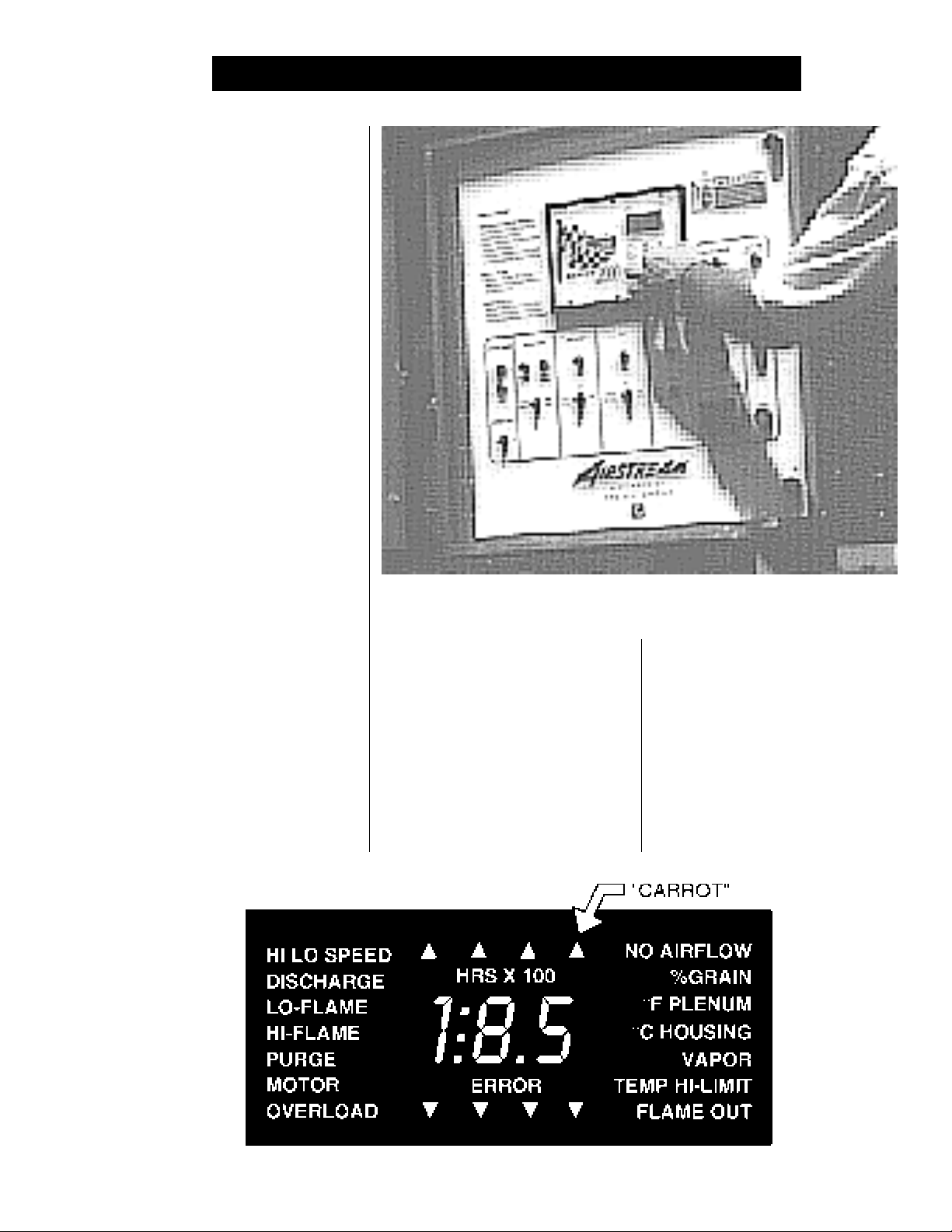
Figure 4: The dryer LCD display.Figure 4: The dryer LCD display.
Figure 4: The dryer LCD display.
Figure 4: The dryer LCD display.Figure 4: The dryer LCD display.
19
Page 20
SERIES 2000 DRYER CONTROL PANELSERIES 2000 DRYER CONTROL PANEL
SERIES 2000 DRYER CONTROL PANEL
SERIES 2000 DRYER CONTROL PANELSERIES 2000 DRYER CONTROL PANEL
the dryer is restarted the timers will
continue timing down. The timers
will return to their initial settings by
pressing and holding the STOP
button for 5 seconds.
SETTING THE LOAD ANDSETTING THE LOAD AND
SETTING THE LOAD AND
SETTING THE LOAD ANDSETTING THE LOAD AND
UNLOAD DELAYSUNLOAD DELAYS
UNLOAD DELAYS
UNLOAD DELAYSUNLOAD DELAYS
The LOAD DELAY is used to delay the
starting of the
dryer is unloading to prevent the
augerauger
auger from starting and stopping too
augerauger
often. The UNLOAD DELAY is used to
control the amount of time the
augerauger
auger runs after the
augerauger
stop to allow for auger cleanout.
1. Press the PROGRAM (DELAYS)
button until the carrot is under the
time delay to be changed.
2. Use the UP and DOWN arrow
keys to change the present time
to the new one. The new time is
load augerload auger
load auger when the
load augerload auger
loadload
load
loadload
unloadunload
unload
unloadunload
metering rollsmetering rolls
metering rolls
metering rollsmetering rolls
automatically entered.
3. Keep pressing the PROGRAM
(DELAYS) button until the car-
rot disappears or press the MODE
SELECT button once to exit.
SETTING THE MOISTURESETTING THE MOISTURE
SETTING THE MOISTURE
SETTING THE MOISTURESETTING THE MOISTURE
CONTROL AND PLENUMCONTROL AND PLENUM
CONTROL AND PLENUM
CONTROL AND PLENUMCONTROL AND PLENUM
SET POINTSET POINT
SET POINT
SET POINTSET POINT
1. Press the PROGRAM (TEM-
PERATURES) button until the
carrot is under the temperature
setting to be changed.
2. Use the UPand DOWN arrow
keys to change the present tem-
perature to the new one. The
new time is automatically entered.
3. Keep pressing the PROGRAM
(TEMPERATURES) button until
the carrot disappears or press the
MODE SELECT button once to exit.
DRYER SAFETY CIRCUITDRYER SAFETY CIRCUIT
DRYER SAFETY CIRCUIT
DRYER SAFETY CIRCUITDRYER SAFETY CIRCUIT
Competitor Series 2000 Con-Competitor Series 2000 Con-
The
Competitor Series 2000 Con-
Competitor Series 2000 Con-Competitor Series 2000 Con-
trol Systemtrol System
trol System continuously checks all
trol Systemtrol System
safety circuits on the dryer, and will
automatically shut the dryer down
should a problem occur. The cause
of the dryer shutdown will be shown
on the LCD display. To restart the
dryer after a safety shutdown, first
correct the reason for the shutdown,
and then press the DRYER POWER
STOP button to reset the circuit.
Press the START button.
MONITORING GRAINMONITORING GRAIN
MONITORING GRAIN
MONITORING GRAINMONITORING GRAIN
TEMPERATURES, PLENUMTEMPERATURES, PLENUM
TEMPERATURES, PLENUM
TEMPERATURES, PLENUMTEMPERATURES, PLENUM
TEMPERATURE OR TIMERSTEMPERATURE OR TIMERS
TEMPERATURE OR TIMERS
TEMPERATURE OR TIMERSTEMPERATURE OR TIMERS
Use the mode select to decide which
of the modes you want to view.
CHECKING THE HOURCHECKING THE HOUR
CHECKING THE HOUR
CHECKING THE HOURCHECKING THE HOUR
METERMETER
METER
METERMETER
Press the UP arrow key and the total
hours on the machine are displayed.
20
Figure 5: The Competitor Series 2000 Control SystemFigure 5: The Competitor Series 2000 Control System
Figure 5: The Competitor Series 2000 Control System
Figure 5: The Competitor Series 2000 Control SystemFigure 5: The Competitor Series 2000 Control System
Page 21

SERIES 2000 DRYER CONTROL PANELSERIES 2000 DRYER CONTROL PANEL
SERIES 2000 DRYER CONTROL PANEL
SERIES 2000 DRYER CONTROL PANELSERIES 2000 DRYER CONTROL PANEL
EMERGENCY COOLINGEMERGENCY COOLING
EMERGENCY COOLING
EMERGENCY COOLINGEMERGENCY COOLING
MODEMODE
MODE
MODEMODE
An emergency cooling mode can be
entered by switching the next to the
top switch (number seven) on the dip
switch located inside the
boxbox
box on the back of the
boxbox
control boardcontrol board
control board. This will enable a
control boardcontrol board
mode, allowing the operator to run
the dryer
is a plenum temperature or grain
high limit warning. When either of
these safeties shuts down the dryer,
fanfan
fan only, in the case there
fanfan
controlcontrol
control
controlcontrol
computercomputer
computer
computercomputer
SAFETY CIRCUIT SHUTDOWN MESSAGESSAFETY CIRCUIT SHUTDOWN MESSAGES
SAFETY CIRCUIT SHUTDOWN MESSAGES
SAFETY CIRCUIT SHUTDOWN MESSAGESSAFETY CIRCUIT SHUTDOWN MESSAGES
SPECIAL FEATURESSPECIAL FEATURES
SPECIAL FEATURES
SPECIAL FEATURESSPECIAL FEATURES
you can run the
grain and/or plenum high limit back
down to a safe level. After changing
the switch press the START button
and only the
mately five minutes.
BURNER ON/OFFBURNER ON/OFF
BURNER ON/OFF
BURNER ON/OFFBURNER ON/OFF
The need has developed for an ON/
burnerburner
OFF
burner in recent years, due to
burnerburner
changing fuel conditions, and also
to aid in drying wheat or other low
temperature grains in hot weather.
fanfan
fan to help cool the
fanfan
fanfan
fan will run for approxi-
fanfan
OPERATIONOPERATION
OPERATION
OPERATIONOPERATION
By moving the third switch (num-
ber six) on the dip switch located in-
side the
the
burner can be changed from a HI-LO
burnerburner
burner to an ON/OFF
burnerburner
tion. The
the same as the HI-LO
ever, when the set point is reached
the
ing to a lower pressure. The vapor-
izer cools quicker and allows a closer
tolerance on the set point.
control boxcontrol box
control box on the back of
control boxcontrol box
computer control boardcomputer control board
computer control board, the
computer control boardcomputer control board
burnerburner
burner opera-
burnerburner
burnerburner
burner will operate exactly
burnerburner
burnerburner
burner, how-
burnerburner
burner burner
burner is cycled off instead of go-
burner burner
VAPOR HIGHVAPOR HIGH
VAPOR HIGH
VAPOR HIGHVAPOR HIGH
TEMPERATURETEMPERATURE
TEMPERATURE
TEMPERATURETEMPERATURE
The LP gas vapor
sensorsensor
sensor located in the
sensorsensor
train train
train downstream from the vapor-
train train
izer, has opened indicating that the
vaporizor is running too hot and
must be readjusted. This
is set at 200°F and automatically
resets itself when cool.
LOSS OF FLAMELOSS OF FLAME
LOSS OF FLAME
LOSS OF FLAMELOSS OF FLAME
flame sensor flame sensor
The
flame sensor has failed to de-
flame sensor flame sensor
tect a burner flame indicating that the
burnerburner
burner has failed to light, there is a
burnerburner
problem with the flame sensing cir-
cuitry or the dryer is not getting
burner fuel.
sition the flame probe, turn off thesition the flame probe, turn off the
sition the flame probe, turn off the
sition the flame probe, turn off thesition the flame probe, turn off the
incoming power to the dryer at theincoming power to the dryer at the
incoming power to the dryer at the
incoming power to the dryer at theincoming power to the dryer at the
main safety disconnect.main safety disconnect.
main safety disconnect.
main safety disconnect.main safety disconnect.
temperature high limit temperature high limit
The
temperature high limit located
temperature high limit temperature high limit
on the
Before trying to repo-Before trying to repo-
Before trying to repo-
Before trying to repo-Before trying to repo-
HOUSING HIGHHOUSING HIGH
HOUSING HIGH
HOUSING HIGHHOUSING HIGH
TEMPERATURETEMPERATURE
TEMPERATURE
TEMPERATURETEMPERATURE
fan/burner housing fan/burner housing
fan/burner housing has
fan/burner housing fan/burner housing
temperaturetemperature
temperature
temperaturetemperature
gas pipegas pipe
gas pipe
gas pipegas pipe
sensorsensor
sensor
sensorsensor
opened, indicating an over tempera-
ture condition has occurred toward
the rear of the
in an oblong covered electrical box.
This control is set at 200°F and must
be manually reset.
REAR DISCHARGEREAR DISCHARGE
REAR DISCHARGE
REAR DISCHARGEREAR DISCHARGE
lid on the grain discharge boxlid on the grain discharge box
The
lid on the grain discharge box
lid on the grain discharge boxlid on the grain discharge box
has opened, indicating that grain is
not being taken away fast enough
at the
One of the
ther the
iary motorsiary motors
iary motors has opened, indicating
iary motorsiary motors
an overcurrent condition. The
loadsloads
loads must be manually reset.
loadsloads
An over temperature condition has
occurred in one of the
umns umns
umns causing the control to shut-
umns umns
down the dryer. This control is set
discharge boxdischarge box
discharge box.
discharge boxdischarge box
MOTOR OVERLOADMOTOR OVERLOAD
MOTOR OVERLOAD
MOTOR OVERLOADMOTOR OVERLOAD
fan, load, unload fan, load, unload
fan, load, unload or
fan, load, unload fan, load, unload
GRAIN HIGHGRAIN HIGH
GRAIN HIGH
GRAIN HIGHGRAIN HIGH
TEMPERATURETEMPERATURE
TEMPERATURE
TEMPERATURETEMPERATURE
fan/heater housingfan/heater housing
fan/heater housing
fan/heater housingfan/heater housing
WARNINGWARNING
WARNING
WARNINGWARNING
thermal overloadsthermal overloads
thermal overloads on ei-
thermal overloadsthermal overloads
auxil-auxil-
auxil-
auxil-auxil-
over-over-
over-
over-over-
grain col-grain col-
grain col-
grain col-grain col-
at 210°F and automatically resets
itself when cool.
OUT OF GRAINOUT OF GRAIN
OUT OF GRAIN
OUT OF GRAINOUT OF GRAIN
The dryer has run low on grain, and
the OUT OF GRAIN TIMER has timed
out, shutting the dryer down. The
load augerload auger
load auger will clean out the dryer if
load augerload auger
in CONTINUOUS FLOW operation.
PLENUM HIGHPLENUM HIGH
PLENUM HIGH
PLENUM HIGHPLENUM HIGH
TEMPERATURETEMPERATURE
TEMPERATURE
TEMPERATURETEMPERATURE
An over temperature condition has
occurred inside the
This control is a 300°F limit and auto-
matically resets itself when cool. See
emergency cooling mode above.
NO AIRFLOWNO AIRFLOW
NO AIRFLOW
NO AIRFLOWNO AIRFLOW
The contacts in the
opened due to insufficient airflow for the
burnerburner
burner to operate, the
burnerburner
air switchair switch
or the
air switch may need adjusting.
air switchair switch
air switchair switch
The
air switch contacts have closed
air switchair switch
prior to the
freewheeling
ting of the
fanfan
fan starting, indicating a
fanfan
blade blade
blade or improper set-
blade blade
air switch air switch
air switch.
air switch air switch
dryer plenumdryer plenum
dryer plenum.
dryer plenumdryer plenum
air switchair switch
air switch have
air switchair switch
fan fan
fan not turning,
fan fan
AIRAIR
AIR
AIRAIR
un-un-
un-
un-un-
21
Page 22

SERIES 2000 ERROR CONDITIONSSERIES 2000 ERROR CONDITIONS
SERIES 2000 ERROR CONDITIONS
SERIES 2000 ERROR CONDITIONSSERIES 2000 ERROR CONDITIONS
ERROR CODE BREAKDOWNERROR CODE BREAKDOWN
ERROR CODE BREAKDOWN
ERROR CODE BREAKDOWNERROR CODE BREAKDOWN
Illegal flame sense. Error 7 is most likely
caused by stuck open solenoid. Error 7 will
not shut down fan until loss of flame is
detected by control. Error 7 may also be
caused by a bad ballast resistor (ballast
resistor not open between poles). It may also
occur if 1 of the 12 volt DC limits is shorted to
ERROR
ERROR
No safety circuit voltage.
AC ground, or either temperature senosr is
shorted to AC ground.
ERROR
ERROR
I/O board communication failure
I/O board and master have lost
communication.
ERROR
ERROR
User supplied safety.
COMPETITOR ERROR CONDITIONS
ERROR
ERROR
Mercoid gas pressure safety.
This indicates that one of the other on
screen errors (vapor, plenum, housing
temp hi-limit, flame out, no airflow, motor
overload or rear discharge) has occured.
ERROR
ERROR
ERROR
ERROR
22
User switched from continuous flow to
batch while dryer is running.
Grain temperature sensor open. One
or both leads are off (open circuit)
(SEE FIGURE 4)
Grain temperature sensor leads are
shorted together OR sensor is shorted.
(See Figure 4)
Plenum temperature sensor is open.
One or both leads are off (open circuit)
(See figure 4)
Plenum temperature senosr leads are
shorted together OR sensor is shorted.
(See figure 4)
Flame probe shorted to AC ground.
Page 23
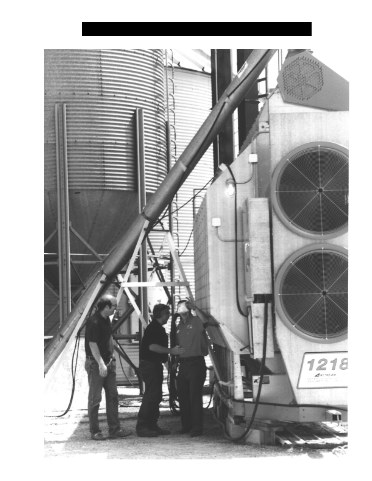
PRE START CHECKS FOR ALL PORTABLE DRYERSPRE START CHECKS FOR ALL PORTABLE DRYERS
PRE START CHECKS FOR ALL PORTABLE DRYERS
PRE START CHECKS FOR ALL PORTABLE DRYERSPRE START CHECKS FOR ALL PORTABLE DRYERS
23
Page 24
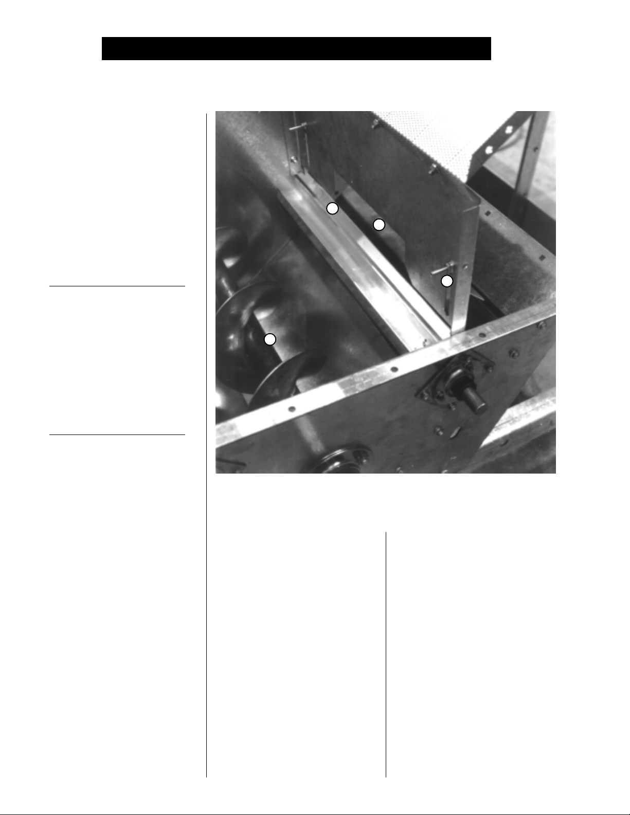
PRE START CHECKS FOR ALL PORTABLE DRYERSPRE START CHECKS FOR ALL PORTABLE DRYERS
PRE START CHECKS FOR ALL PORTABLE DRYERS
PRE START CHECKS FOR ALL PORTABLE DRYERSPRE START CHECKS FOR ALL PORTABLE DRYERS
Before the dryer is filled, thoroughly
inspect the unit and check the op-
eration of the dryer as follows.
INSPECT THE METERINGINSPECT THE METERING
INSPECT THE METERING
INSPECT THE METERINGINSPECT THE METERING
ROLLSROLLS
ROLLS
ROLLSROLLS
Open all
doorsdoors
doors and inspect each compart-
doorsdoors
ment for any bolts, nuts or other for-
eign material, that may cause pos-
sible jamming of the
metering roll accessmetering roll access
metering roll access
metering roll accessmetering roll access
metering rollsmetering rolls
metering rolls.
metering rollsmetering rolls
BEFORE ATTEMPTING TO
OPERATE THE DRYER MAKE
SURE ALL SAFETY SHIELDS
ARE IN PLACE, ALL BOTTOM
CLEANOUT AND REAR
ACCESS DOORS ARE CLOSED
AND ALL PERSONNEL ARE
CLEAR OF THE DRYER
PRE SEASON INSPECTIONPRE SEASON INSPECTION
PRE SEASON INSPECTION
PRE SEASON INSPECTIONPRE SEASON INSPECTION
11
1
11
22
2
22
44
4
44
33
3
33
SET CONTROL SWITCHESSET CONTROL SWITCHES
SET CONTROL SWITCHES
SET CONTROL SWITCHESSET CONTROL SWITCHES
Moisture Control Switch-ON
Moisture Control Thermostat-MINI-
MUM TEMPERATURE
Adjustable Grain Hi-Limit-MAXI-
MUM TEMPERATURE*
Load Switch-OFF
Unload Switch-OFF
Fan Switches-OFF
Burner Switches-OFF
Out of Grain Timer-1 MINUTE
Load Delay-30 SECONDS
Unload Delay-30 SECONDS
Metering Roll Speed-LOW AND
HIGH SPEED--000
Dry Timer-1 MINUTE
Cool timer-1 MINUTE
Unload timer-30 SECONDS
Mode Switch-CONTINUOUS FLOW
*On multi-fan models
The metering roll access area: 1-Metering roll, 2-Strike-off plate, 3-Adjust-The metering roll access area: 1-Metering roll, 2-Strike-off plate, 3-Adjust-
The metering roll access area: 1-Metering roll, 2-Strike-off plate, 3-Adjust-
The metering roll access area: 1-Metering roll, 2-Strike-off plate, 3-Adjust-The metering roll access area: 1-Metering roll, 2-Strike-off plate, 3-Adjust-
ing bolt, 4-Unload auger.ing bolt, 4-Unload auger.
ing bolt, 4-Unload auger.
ing bolt, 4-Unload auger.ing bolt, 4-Unload auger.
ELECTRICAL POWERELECTRICAL POWER
ELECTRICAL POWER
ELECTRICAL POWERELECTRICAL POWER
Turn ON the
plyply
ply to the dryer; set all
plyply
ersers
ers to ON, including the
ersers
connect handleconnect handle
connect handle mounted on the
connect handleconnect handle
front of the
CONTROL POWER SWITCHCONTROL POWER SWITCH
CONTROL POWER SWITCH
CONTROL POWER SWITCHCONTROL POWER SWITCH
Turn the CONTROL POWER switch
to ON. The switch will light up. A
copyright message, model number,
total running time in hours and min-
utes, current date and time will ap-
pear. At this point the controller will
lock out all other dryer functions.
electrical power sup-electrical power sup-
electrical power sup-
electrical power sup-electrical power sup-
circuit break-circuit break-
circuit break-
circuit break-circuit break-
safety dis-safety dis-
safety dis-
safety dis-safety dis-
dryer power paneldryer power panel
dryer power panel.
dryer power paneldryer power panel
Once the date and time appear,
press RESET and the dryer will per-
form its safety circuit check. If a fault
is found, the cause will be displayed
on the LCD. If all are found safe,
the controller will supply power to the
electronic fuel shut-off valveelectronic fuel shut-off valve
electronic fuel shut-off valve, if so
electronic fuel shut-off valveelectronic fuel shut-off valve
equipped, and the DRYING MODE
switch will light up, indicating that the
dryer is ready to be started.
POWER START BUTTONPOWER START BUTTON
POWER START BUTTON
POWER START BUTTONPOWER START BUTTON
Push the DRYER START button,
and all the selector switches on the
control panel will be activated.
24
Page 25
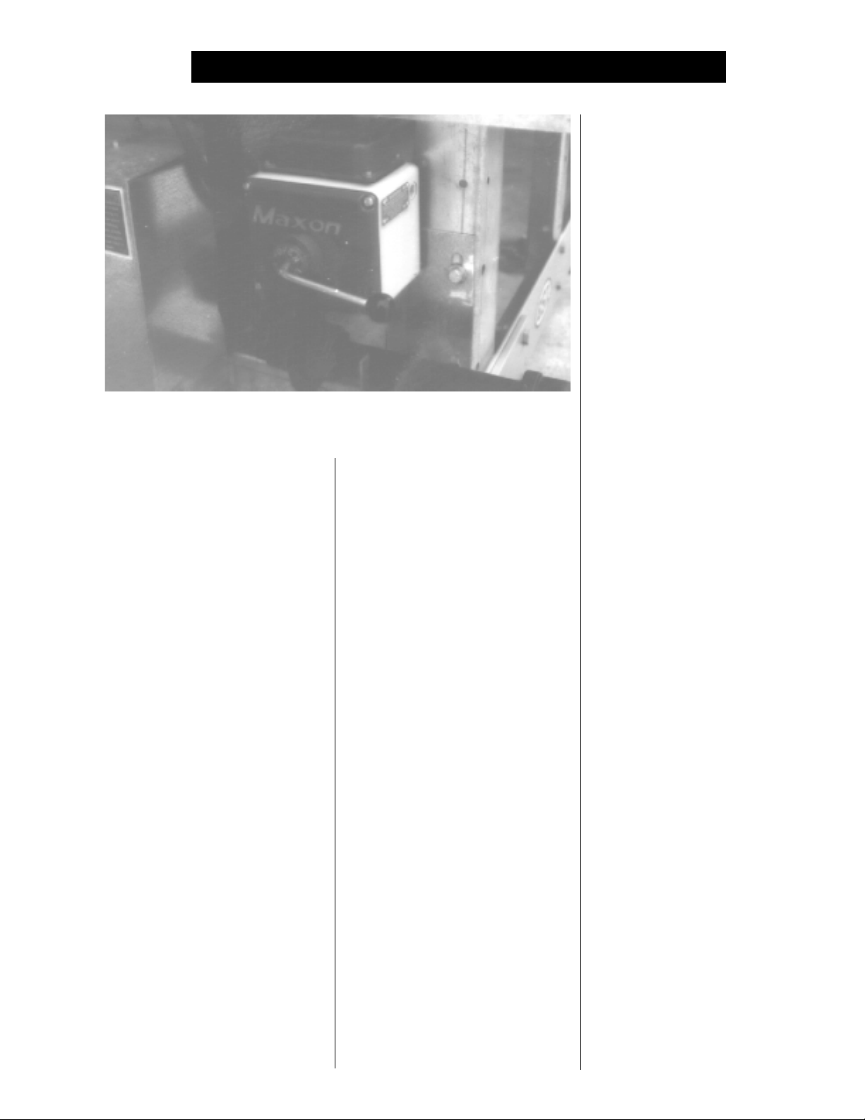
PRE START CHECKS FOR ALL PORTABLE DRYERSPRE START CHECKS FOR ALL PORTABLE DRYERS
PRE START CHECKS FOR ALL PORTABLE DRYERS
PRE START CHECKS FOR ALL PORTABLE DRYERSPRE START CHECKS FOR ALL PORTABLE DRYERS
The Maxon safety shut off valve.The Maxon safety shut off valve.
The Maxon safety shut off valve.
The Maxon safety shut off valve.The Maxon safety shut off valve.
FUEL CHECKFUEL CHECK
FUEL CHECK
FUEL CHECKFUEL CHECK
If using LP gas, make sure the tank
has plenty of fuel and that the tank
does not have a regulator mounted
to it. If using natural gas, make sure
an adequate supply is available.
If using LP gas, slowly OPEN
the main
tank. If using natural gas, turn ON
the
Then, OPEN the electronic
valve valve
valve (Maxon valve), if so equipped,
valve valve
or OPEN the manual
on the dryer to allow fuel flow to the
dryer. Inspect all
nections nections
nections for possible leaks.
nections nections
gas leaks must be fixed immedi-gas leaks must be fixed immedi-
gas leaks must be fixed immedi-
gas leaks must be fixed immedi-gas leaks must be fixed immedi-
ately!ately!
ately!
ately!ately!
With the grain supply SHUTOFF,
quickly bump the LOAD AUGER
switch to MANUAL, and see if the
load auger load auger
load auger rotates clockwise as
load auger load auger
viewed from the drive end, or coun-
terclockwise if the dryer is a front
load model. If the wet grain supply
auxiliary is wired to the dryer
fuel supply valvefuel supply valve
fuel supply valve at the
fuel supply valvefuel supply valve
valve valve
valve along the supply line.
valve valve
shut offshut off
shut off
shut offshut off
shut off valveshut off valve
shut off valve
shut off valveshut off valve
gas lines and con-gas lines and con-
gas lines and con-
gas lines and con-gas lines and con-
AnyAny
Any
AnyAny
LOAD AUGERLOAD AUGER
LOAD AUGER
LOAD AUGERLOAD AUGER
it should also rotate in the correct
direction at this time. Turn the LOAD
AUGER switch to the AUTO (timed
shutdown) position. The
wet grain supply auxiliarywet grain supply auxiliary
and
wet grain supply auxiliary
wet grain supply auxiliarywet grain supply auxiliary
should run for one minute, and then
the dryer will shutdown leaving the
safety shutdown message OUT OF
GRAIN WARNING displayed. Press
the DRYER POWER STOP button
to reset the panel, then press the
START button.
ONE SPEED OPERATIONONE SPEED OPERATION
ONE SPEED OPERATION
ONE SPEED OPERATIONONE SPEED OPERATION
To check 1 SPEED operation place
the UNLOAD switch to the 1 SPEED
setting. Turn up the HIGH speed
metering roll dial until the
rollsrolls
rolls start rotating. The
rollsrolls
ger ger
ger should rotate counterclockwise
ger ger
as viewed from the drive end. The
metering roll drive motormetering roll drive motor
metering roll drive motor should
metering roll drive motormetering roll drive motor
rotate clockwise as viewed from the
drive end of the
grain take away auxiliarygrain take away auxiliary
grain take away auxiliary is wired
grain take away auxiliarygrain take away auxiliary
to the dryer, it should start and ro-
tate in the proper direction.
gear boxgear box
gear box. If the
gear boxgear box
top augertop auger
top auger
top augertop auger
meteringmetering
metering
meteringmetering
bottom au-bottom au-
bottom au-
bottom au-bottom au-
drydry
dry
drydry
MOISTURE CONTROLMOISTURE CONTROL
MOISTURE CONTROL
MOISTURE CONTROLMOISTURE CONTROL
THERMOSTATTHERMOSTAT
THERMOSTAT
THERMOSTATTHERMOSTAT
To check the MOISTURE CON-
TROL THERMOSTAT leave the
UNLOAD switch on 1 SPEED, and
slowly turn down the MOISTURE
CONTROL THERMOSTAT. As the
setting is increased, the indicator
light should come on and the
tering rolls tering rolls
tering rolls should stop operating.
tering rolls tering rolls
bottom augerbottom auger
The
bottom auger will stop after the
bottom augerbottom auger
30 second clean out delay, provid-
ing that the dryer is still being held
by the MOISTURE CONTROL
THERMOSTAT. Rotate the MOIS-
TURE CONTROL THERMOSTAT
down to its minimum setting. The
light should go OFF, and the
ing rollsing rolls
ing rolls should restart along with
ing rollsing rolls
bottom augerbottom auger
the
bottom auger if it has stopped.
bottom augerbottom auger
TWO SPEED OPERATIONTWO SPEED OPERATION
TWO SPEED OPERATION
TWO SPEED OPERATIONTWO SPEED OPERATION
To check 2 SPEED operation move
the UNLOAD switch to the 2 SPEED
position, set LOW speed on 200 and
HIGH speed on 600. Slowly turn the
THERMOSTAT until the MOIS-
TURE CONTROL switch light
comes ON. The metering roll speed
is now controlled by the LOW speed
dial. Turning the THERMOSTAT the
other way until the light goes out
leaves the
by the HIGH speed dial.
To check the
turn either the LOW speed or HIGH
speed knob clockwise, and the me-
tering roll speed should INCREASE.
Turning either knob counterclockwise
will DECREASE the speed. Make
metering rolls metering rolls
metering rolls controlled
metering rolls metering rolls
METERING ROLLMETERING ROLL
METERING ROLL
METERING ROLLMETERING ROLL
OPERATIONOPERATION
OPERATION
OPERATIONOPERATION
metering roll metering roll
metering roll operation
metering roll metering roll
me-me-
me-
me-me-
meter-meter-
meter-
meter-meter-
25
Page 26
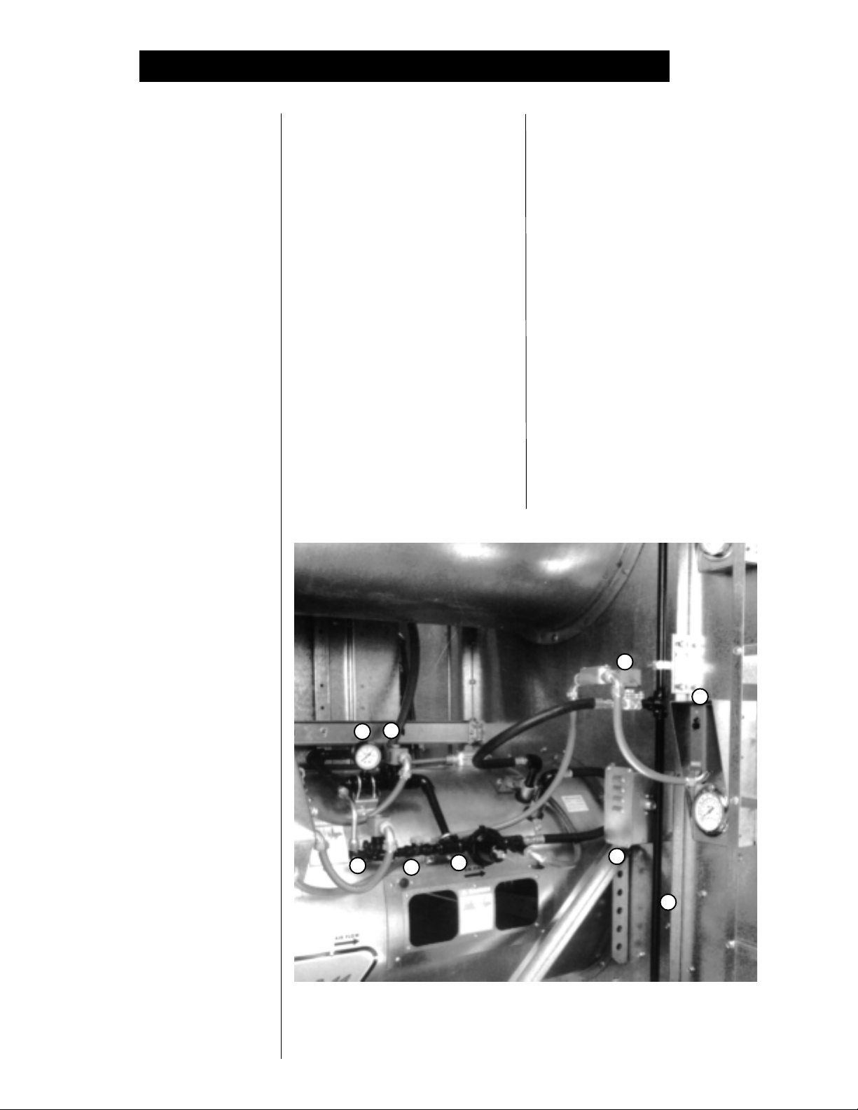
PRE START CHECKS FOR ALL PORTABLE DRYERSPRE START CHECKS FOR ALL PORTABLE DRYERS
PRE START CHECKS FOR ALL PORTABLE DRYERS
PRE START CHECKS FOR ALL PORTABLE DRYERSPRE START CHECKS FOR ALL PORTABLE DRYERS
sure the
erly adjusted and all sections of the
metering rollsmetering rolls
metering rolls rotate. Turn the UN-
metering rollsmetering rolls
LOAD switch OFF after these
checks are complete. The
auger auger
auger will continue to run for 30 sec-
auger auger
onds after the switch is turned OFF
to allow for cleanout.
Bump each FAN switch and observe
the
counterclockwise. Sometimes on
three phase models all
run backwards. They can easily be
reversed by interchanging two of the
three
verse the two outside wires, L1 and
L3, and leave the middle one in the
same position.
fans or burnersfans or burners
fans or burners will not operate.
fans or burnersfans or burners
The
static pressure to engage the
switchswitch
switch. You will receive a LOSS OF
switchswitch
AIRFLOW message.
To check the
first make sure the main GAS VALVE
is OFF. Turn the FAN switch ON and
allow the
HEATER switch ON for that
dryer will shut down after 20 seconds.
The safety message, BURNER 1
WARNING FLAME NOT DETECTED
will appear. Restart dryer and repeat
other
drive chain drive chain
drive chain tension is prop-
drive chain drive chain
bottom bottom
bottom
bottom bottom
FAN SWITCHESFAN SWITCHES
FAN SWITCHES
FAN SWITCHESFAN SWITCHES
fan fan
fan rotation. The
fan fan
power supply wirespower supply wires
power supply wires. Re-
power supply wirespower supply wires
Note: If the dryer is empty, the
fansfans
fans cannot create enough
fansfans
BURNER SAFETYBURNER SAFETY
BURNER SAFETY
BURNER SAFETYBURNER SAFETY
burner burner
burner safety function,
burner burner
fan fan
fan to start. Then, turn the
fan fan
fans/heatersfans/heaters
fans/heaters.
fans/heatersfans/heaters
fan fan
fan should run
fan fan
motors motors
motors will
motors motors
airair
air
airair
fanfan
fan. The
fanfan
burnerburner
burner should ignite after a short
burnerburner
purge delay of approximately 10
seconds. Gas pressure should be
shown on the gauge. Adjust the
BURNER HI-LO FIRE THERMO-
STAT to 200°F, causing the
to operate on hi-fire. This
statstat
stat is located on the front left side
statstat
of the dryer. Observe the gas pres-
sure on gauge, and turn the
mostat mostat
mostat to its minimum setting, caus-
mostat mostat
ing the
As the
down the gas pressure should also
show a noticeable drop, indicating that
the
burnerburner
burner is being supplied with less gas
burnerburner
through the
burnerburner
burner to cycle into lo-fire.
burnerburner
burner thermostatburner thermostat
burner thermostat is turned
burner thermostatburner thermostat
hi-fire solenoidhi-fire solenoid
hi-fire solenoid is closed and the
hi-fire solenoidhi-fire solenoid
lo-fire control valve.lo-fire control valve.
lo-fire control valve.
lo-fire control valve.lo-fire control valve.
33
3
33
99
9
99
44
4
44
22
2
22
burnerburner
burner
burnerburner
thermo-thermo-
thermo-
thermo-thermo-
11
1
11
ther-ther-
ther-
ther-ther-
Set the hi-fire and lo-fire pressure
settings. Use the PRESSURE
REGULATOR for hi-fire and the ball
valve for lo-fire. The
should cycle between hi and lo, ap-
proximately 4 to 5 times per minute.
Approximate settings should be:
LP Gas Hi-Fire 6-15 lbs.
Lo-Fire 2-6 lbs.
Natural Gas Hi-Fire 6-10 lbs.
Lo-Fire 1-3 lbs.
burnerburner
If the
burner remains on hi-fire
burnerburner
and does not cycle, INCREASE the
regulator setting on the propane
models, or the supply valve on the
natural gas models in order to reach
thermostat thermostat
the
thermostat setting. If the
thermostat thermostat
remains in lo-fire and does not
77
7
77
88
8
88
thermostatthermostat
thermostat
thermostatthermostat
55
5
55
66
6
66
burnerburner
burner
burnerburner
BURNER TEST FIREBURNER TEST FIRE
BURNER TEST FIRE
BURNER TEST FIREBURNER TEST FIRE
START the
BURNER switch to ON. Turn ON
the FUEL supply, and the
26
fanfan
fan and turn the
fanfan
The dryer fan and heater controls featuring: 1-pressure regulator, 2-low-fireThe dryer fan and heater controls featuring: 1-pressure regulator, 2-low-fire
The dryer fan and heater controls featuring: 1-pressure regulator, 2-low-fire
The dryer fan and heater controls featuring: 1-pressure regulator, 2-low-fireThe dryer fan and heater controls featuring: 1-pressure regulator, 2-low-fire
control valve, 3-high pressure solenoid, 4-low pressure solenoid, 5-hi-lowcontrol valve, 3-high pressure solenoid, 4-low pressure solenoid, 5-hi-low
control valve, 3-high pressure solenoid, 4-low pressure solenoid, 5-hi-low
control valve, 3-high pressure solenoid, 4-low pressure solenoid, 5-hi-lowcontrol valve, 3-high pressure solenoid, 4-low pressure solenoid, 5-hi-low
fire thermostat, 6-fuel supply line, 7-LP solenoid or supply ball valve(NG),fire thermostat, 6-fuel supply line, 7-LP solenoid or supply ball valve(NG),
fire thermostat, 6-fuel supply line, 7-LP solenoid or supply ball valve(NG),
fire thermostat, 6-fuel supply line, 7-LP solenoid or supply ball valve(NG),fire thermostat, 6-fuel supply line, 7-LP solenoid or supply ball valve(NG),
8-air pressure switch and 9-liquid filled gauge.8-air pressure switch and 9-liquid filled gauge.
8-air pressure switch and 9-liquid filled gauge.
8-air pressure switch and 9-liquid filled gauge.8-air pressure switch and 9-liquid filled gauge.
Page 27

PRE START CHECKS FOR ALL PORTABLE DRYERSPRE START CHECKS FOR ALL PORTABLE DRYERS
PRE START CHECKS FOR ALL PORTABLE DRYERS
PRE START CHECKS FOR ALL PORTABLE DRYERSPRE START CHECKS FOR ALL PORTABLE DRYERS
All dryer functions should be checked before operation each season.All dryer functions should be checked before operation each season.
All dryer functions should be checked before operation each season.
All dryer functions should be checked before operation each season.All dryer functions should be checked before operation each season.
cycle, slightly decease gas pressure
with the LO-FIRE CONTROL VALVE.
If the gas pressure is decreased too
much a popping or fluttering sound will
be heard. Also, anytime the high pres-
sure side is adjusted, the low pres-
sure side needs to be checked. Re-
peat the test for each
STAGED BATCH CHECKSTAGED BATCH CHECK
STAGED BATCH CHECK
STAGED BATCH CHECKSTAGED BATCH CHECK
1. Turn the CONTROL POWER
switch to the ON position.
2. Turn the DRYING MODE switch to
the STAGED BATCH position.
3. Press the RESET button, OPEN
the main FUEL SUPPLY VALVE
at the tank on an LP dryer, or
valve in the FUEL SUPPLY
LINE on a natural gas dryer.
fan/heaterfan/heater
fan/heater unit.
fan/heaterfan/heater
4. Turn ON the ELECTRIC SHUT
OFF valve to allow fuel flow to
the dryer, if so equipped.
5. Turn the LOAD switch to AUTO
and UNLOAD switch to 1 SPEED.
6. Push the dryer POWER START
button, and the controller will se-
quentially start all dryer compo-
nents in their proper order.
If any switches are not in their cor-
rect position for STAGED BATCH
operation, the dryer will indicate im-
proper switch position, and will not
start until the switches are properly
set. After starting, all BATCH TIM-
ERS will time down in sequence.
When the unload cycle is complete
the timers will automatically reset to
their original settings, and start the
dry timer again.
DRYER SHUTDOWNDRYER SHUTDOWN
DRYER SHUTDOWN
DRYER SHUTDOWNDRYER SHUTDOWN
To shutdown the dryer, first CLOSE
the FUEL SUPPLY VALVE at the
tank or valve along the fuel line. If
burner burner
the
burner is operating, let the dryer
burner burner
run out of fuel, and it will shut down
automatically due to loss of flame.
CLOSE the FUEL VALVE at the
dryer, and press the dryer POWER
STOP button. Turn OFF the
disconnect handledisconnect handle
disconnect handle on the front of
disconnect handledisconnect handle
power boxpower box
the
power box, and turn OFF the
power boxpower box
main POWER to the dryer.
EMERGENCYEMERGENCY
EMERGENCY
EMERGENCYEMERGENCY
In case of emergency push the dryer
POWER STOP button. The
all augers all augers
and
all augers will stop immediately.
all augers all augers
safetysafety
safety
safetysafety
fan, burner fan, burner
fan, burner
fan, burner fan, burner
27
Page 28

STARTUP & OPERATION FOR ALL PORTABLE DRYERSSTARTUP & OPERATION FOR ALL PORTABLE DRYERS
STARTUP & OPERATION FOR ALL PORTABLE DRYERS
STARTUP & OPERATION FOR ALL PORTABLE DRYERSSTARTUP & OPERATION FOR ALL PORTABLE DRYERS
28
Page 29

STARTUP & OPERATION FOR ALL PORTABLE DRYERSSTARTUP & OPERATION FOR ALL PORTABLE DRYERS
STARTUP & OPERATION FOR ALL PORTABLE DRYERS
STARTUP & OPERATION FOR ALL PORTABLE DRYERSSTARTUP & OPERATION FOR ALL PORTABLE DRYERS
CONTINUOUS FLOW AND CONTINUOUS BATCH STARTUP PROCEDURECONTINUOUS FLOW AND CONTINUOUS BATCH STARTUP PROCEDURE
CONTINUOUS FLOW AND CONTINUOUS BATCH STARTUP PROCEDURE
CONTINUOUS FLOW AND CONTINUOUS BATCH STARTUP PROCEDURECONTINUOUS FLOW AND CONTINUOUS BATCH STARTUP PROCEDURE
At the beginning of each harvest and
before filling the dryer with grain
make sure to inspect the dryer for
rodent damage, proper belt and
chain tension and missing or dam-
aged safety shields. Test operate
the dryer using the pre start check
procedures located on pages 23-27.
1. Before attempting to operate the
dryer make sure that all
shields shields
shields are in place, all
shields shields
bottom closure panel doorsbottom closure panel doors
bottom closure panel doors are
bottom closure panel doorsbottom closure panel doors
closed, all
are closed and all personnel
are clear of the grain dryer and
grain handling machinery.
2. Turn all SELECTOR switches
on the
position.
3. Turn ON the electrical POWER
supply to the dryer, and move
the SAFETY DISCONNECT
handle mounted on the dryer's
upper upper
upper
upper upper
4. Turn the CONTROL POWER
switch to ON. The switch will
light up. A copyright message,
model number, total running
time in hours and minutes, cur-
rent date and time will appear.
At this point the controller will
lock out all other dryer functions.
5. Once the date and time appear,
press RESET, and the dryer will
perform its safety circuit checks.
If a fault is found the cause will
rear access doorsrear access doors
rear access doors
rear access doorsrear access doors
control panelcontrol panel
control panel to the OFF
control panelcontrol panel
power boxpower box
power box to ON.
power boxpower box
safetysafety
safety
safetysafety
plenumplenum
plenum
plenumplenum
be displayed on the LCD. If all
safeties do not detect a problem,
the controller will energize the
electronic FUEL SHUTOFF
VALVE, if so equipped, and
the DRYING MODE switch will
light up,indicating that the dryer
is ready to be started.
6. Move the LOAD AUGER switch
to MANUAL, and push the dryer
POWER START switch. The
top augertop auger
top auger will immediately start,
top augertop auger
and the LOAD AUGER switch
will light up. If additional loading
equipment is wired to the dryer it
will also start immediately.
7. When the dryer is full of grain
top auger top auger
the
top auger will stop automati-
top auger top auger
cally, and any auxiliary loading
equipment wired to the dryer will
also stop.
CONTINUOUS FLOWCONTINUOUS FLOW
CONTINUOUS FLOW
CONTINUOUS FLOWCONTINUOUS FLOW
OPERATIONOPERATION
OPERATION
OPERATIONOPERATION
1. Turn the CONTROL POWER
switch to ON.
2. After the date and time appear
on screen, press the RESET
button.
3. Push the dryer POWER START
switch.
4. OPEN the main FUEL SUPPLY
VALVE on the tank if using LP
gas, or OPEN the FUEL SUPPLY
LINE if us
ON the
ing natural gas. Turn
Maxon ELECTRIC
SHUTOFF valve, if so equipped,
or OPEN the manual SHUTOFF
VALVE to allow fuel flow to the
dryer.
5. Turn the DRYING MODE switch
to CONTINUOUS FLOW.
6. The dryer should already be
filled with grain. Turn the LOAD
AUGER switch to the AUTO po-
sition. In both the AUTO and
MANUAL positions, the dryer
grain level switch will automati-
cally keep the dryer full of grain.
In the AUTO position the dryer
will shutdown after a preset time
period set on the OUT OF
GRAIN timer if grain flow is in-
terrupted to the dryer.
7. Turn each FAN switch to ON.
fan fan
The
fan will start, and the switch
fan fan
will light up when airflow is de-
tected.
8. Start each
HEATER switch to ON. After
purging for approximately 10
seconds the
the HEATER switch will light up.
This indicates that the flame
sensing circuit is sensing burner
flame.
ing
pre start
9. Operate the
for 6-7 minutes per point of
moisture to be removed with
plenum temperature set
burnerburner
burner by turning the
burnerburner
burner burner
burner will fire, and
burner burner
For information concern
burner burner
burner
burner burner
adjustment see the
section of this manual.
heatersheaters
heaters to dry grain
heatersheaters
the
at
29
Page 30

STARTUP & OPERATION FOR ALL PORTABLE DRYERSSTARTUP & OPERATION FOR ALL PORTABLE DRYERS
STARTUP & OPERATION FOR ALL PORTABLE DRYERS
STARTUP & OPERATION FOR ALL PORTABLE DRYERSSTARTUP & OPERATION FOR ALL PORTABLE DRYERS
120 & 1200 SERIES CONTINUOUS FLOW METERING ROLL SETTINGS120 & 1200 SERIES CONTINUOUS FLOW METERING ROLL SETTINGS
120 & 1200 SERIES CONTINUOUS FLOW METERING ROLL SETTINGS
120 & 1200 SERIES CONTINUOUS FLOW METERING ROLL SETTINGS120 & 1200 SERIES CONTINUOUS FLOW METERING ROLL SETTINGS
Full Heat
Initial
Moisture
Moisture
Removed
Approx.
Dry Time
1 Speed
2 Speed
Low
2 Speed
High
17%
18%
19%
20%
21%
22%
23%
24%
25%
26%
27%
28%
29%
30%
2 pts.
3 pts.
4 pts.
5 pts.
6 pts.
7 pts.
8 pts.
9 pts.
10 pts.
11 pts.
12 pts.
13 pts.
14 pts.
15 pts.
16 min.
21 min.
26 min
31.5 min.
37 min.
41.5 min.
47 min.
51 min.
54 min.
58 min.
62 min.
66.5 min.
71.5 min.
76 min.
625
476
385
317
270
241
213
196
185
172
161
150
140
132
317
270
241
213
196
185
172
161
150
140
132
123
116
110
875
775
675
575
476
385
317
270
241
213
196
185
172
161
31%
32%
33%
34%
35%
These are approximate starting points.
16 pts.
17 pts.
18 pts.
19 pts.
20 pts.
81 min.
86 min.
91 min.
96 min.
100 min.
123
116
110
104
100
104
100
096
087
082
150
140
132
123
116
30
Page 31

STARTUP & OPERATION FOR ALL PORTABLE DRYERSSTARTUP & OPERATION FOR ALL PORTABLE DRYERS
STARTUP & OPERATION FOR ALL PORTABLE DRYERS
STARTUP & OPERATION FOR ALL PORTABLE DRYERSSTARTUP & OPERATION FOR ALL PORTABLE DRYERS
120 & 1200 SERIES CONTINUOUS FLOW METERING ROLL SETTINGS120 & 1200 SERIES CONTINUOUS FLOW METERING ROLL SETTINGS
120 & 1200 SERIES CONTINUOUS FLOW METERING ROLL SETTINGS
120 & 1200 SERIES CONTINUOUS FLOW METERING ROLL SETTINGS120 & 1200 SERIES CONTINUOUS FLOW METERING ROLL SETTINGS
Dry & Cool
Initial
Moisture
Moisture
Removed
Approx.
Dry Time
1 Speed
2 Speed
Low
2 Speed
High
17%
18%
19%
20%
21%
22%
23%
24%
25%
26%
27%
28%
29%
30%
2 pts.
3 pts.
4 pts.
5 pts.
6 pts.
7 pts.
8 pts.
9 pts.
10 pts.
11 pts.
12 pts.
13 pts.
14 pts.
15 pts.
18 min.
24 min.
30 min
35 min.
40 min.
45 min.
50 min.
55 min.
60 min.
65 min.
70 min.
75 min.
80 min.
85 min.
363
272
218
187
163
145
131
119
109
101
093
087
082
077
187
163
145
131
119
109
101
093
087
082
077
073
069
065
650
550
450
363
272
218
187
163
145
131
119
109
101
093
31%
32%
33%
34%
35%
These are approximate starting points.
16 pts.
17 pts.
18 pts.
19 pts.
20 pts.
90 min.
95 min.
100 min.
105 min.
110 min.
073
069
065
062
059
061
057
053
049
045
087
082
077
073
069
31
Page 32

STARTUP & OPERATION FOR ALL PORTABLE DRYERSSTARTUP & OPERATION FOR ALL PORTABLE DRYERS
STARTUP & OPERATION FOR ALL PORTABLE DRYERS
STARTUP & OPERATION FOR ALL PORTABLE DRYERSSTARTUP & OPERATION FOR ALL PORTABLE DRYERS
1200S SERIES CONTINUOUS FLOW METERING ROLL SETTINGS1200S SERIES CONTINUOUS FLOW METERING ROLL SETTINGS
1200S SERIES CONTINUOUS FLOW METERING ROLL SETTINGS
1200S SERIES CONTINUOUS FLOW METERING ROLL SETTINGS1200S SERIES CONTINUOUS FLOW METERING ROLL SETTINGS
Full Heat
Initial
Moisture
Moisture
Removed
Approx.
Dry Time
1 Speed
2 Speed
Low
2 Speed
High
17%
18%
19%
20%
21%
22%
23%
24%
25%
26%
27%
28%
29%
30%
2 pts.
3 pts.
4 pts.
5 pts.
6 pts.
7 pts.
8 pts.
9 pts.
10 pts.
11 pts.
12 pts.
13 pts.
14 pts.
15 pts.
16 min.
21 min.
26 min
31.5 min.
37 min.
41.5 min.
47 min.
51 min.
54 min.
58 min.
62 min.
66.5 min.
71.5 min.
76 min.
655
499
403
333
283
252
223
205
194
181
170
158
147
138
333
283
252
223
205
194
181
170
158
147
138
129
122
115
850
760
670
580
499
403
333
283
252
223
205
194
181
170
31%
32%
33%
34%
35%
These are approximate starting points.
16 pts.
17 pts.
18 pts.
19 pts.
20 pts.
81 min.
86 min.
91 min.
96 min.
100 min.
129
122
115
109
105
109
105
099
093
087
158
147
138
129
122
32
Page 33

STARTUP & OPERATION FOR ALL PORTABLE DRYERSSTARTUP & OPERATION FOR ALL PORTABLE DRYERS
STARTUP & OPERATION FOR ALL PORTABLE DRYERS
STARTUP & OPERATION FOR ALL PORTABLE DRYERSSTARTUP & OPERATION FOR ALL PORTABLE DRYERS
1200S SERIES CONTINUOUS FLOW METERING ROLL SETTINGS1200S SERIES CONTINUOUS FLOW METERING ROLL SETTINGS
1200S SERIES CONTINUOUS FLOW METERING ROLL SETTINGS
1200S SERIES CONTINUOUS FLOW METERING ROLL SETTINGS1200S SERIES CONTINUOUS FLOW METERING ROLL SETTINGS
Dry & Cool
Initial
Moisture
Moisture
Removed
Approx.
Dry Time
1 Speed
2 Speed
Low
2 Speed
High
17%
18%
19%
20%
21%
22%
23%
24%
25%
26%
27%
28%
29%
30%
2 pts.
3 pts.
4 pts.
5 pts.
6 pts.
7 pts.
8 pts.
9 pts.
10 pts.
11 pts.
12 pts.
13 pts.
14 pts.
15 pts.
18 min.
24 min.
30 min
35 min.
40 min.
45 min.
50 min.
55 min.
60 min.
65 min.
70 min.
75 min.
80 min.
85 min.
293
220
176
151
132
117
106
096
088
081
075
070
066
062
151
132
117
106
096
088
081
075
070
066
062
059
056
053
420
370
320
270
220
176
151
132
117
106
096
088
081
075
31%
32%
33%
34%
35%
These are approximate starting points.
16 pts.
17 pts.
18 pts.
19 pts.
20 pts.
90 min.
95 min.
100 min.
105 min.
110 min.
059
056
053
050
048
050
048
045
042
039
070
066
062
059
056
33
Page 34

STARTUP & OPERATION FOR ALL PORTABLE DRYERSSTARTUP & OPERATION FOR ALL PORTABLE DRYERS
STARTUP & OPERATION FOR ALL PORTABLE DRYERS
STARTUP & OPERATION FOR ALL PORTABLE DRYERSSTARTUP & OPERATION FOR ALL PORTABLE DRYERS
180°F. Example: Shelled corn
starts with 25% moisture and
the final moisture content is to
be 15%
the all heat dryeration process,
the estimated drying time is 60
minutes (10 x 6).
10. While operating the dryer adjust
the METERING ROLL dials to the
recommended settings. See the
charts on pages 30 through 33.
11. To move grain through the dryer
turn the MOISTURE CONTROL
switch to ON. The switch will
light up.
Note: When the UNLOAD switch is
in the 2 SPEED position, and the
MOISTURE CONTROL THERMO-
STAT switch is OFF, the speed of
metering rolls metering rolls
the
metering rolls can be manually
metering rolls metering rolls
adjusted by turning the HIGH speed
metering roll dial. Turning the dial
clockwise will INCREASE the grain
discharge rate, counterclockwise
will DECREASE the discharge
rate. (The numbers on the speed
dials indicate the percentage of full
speed.)
12. At the end of the startup period,
start the flow of grain out of the
dryer. Turn the UNLOAD switch
to the 2 SPEED position. The
bottom augerbottom auger
bottom auger and
bottom augerbottom auger
will immediately start, and the
UNLOAD switch will light. If ad
ditional unloading equipment is
utilizing the unload auxiliary
over
dryer, this equipment will also
immediately start.
34
(10% removal). Using
metering rollmetering roll
metering roll
metering rollmetering roll
load supplied with the
13.
To shut the dryer down,
the FUEL SUPPLY VALVE at
the fuel tank or fuel source. Let
the dryer run until the fuel sup-
ply lines drain, and the dryer
automatically shuts down due to
loss of flame. CLOSE the FUEL
VALVE at the dryer. Press the
dryer POWER STOP button.
Turn OFF the dryer's SAFETY
DISCONNECT HANDLE. Turn
OFF the main POWER supply
14. In case of emergency push the
dryer STOP button. The
burnersburners
burners and
burnersburners
immediately.
Note: The
Control System Control System
Control System can be used to au-
Control System Control System
tomatically start the dryer. Place all
the control panel SELECTOR
switches in the proper position.
OPEN the electric FUEL SHUTOFF
VALVE before pressing the dryer
POWER START button. The con-
troller will start all dryer components
in their proper order.
CONTINUOUS BATCHCONTINUOUS BATCH
CONTINUOUS BATCH
CONTINUOUS BATCHCONTINUOUS BATCH
(STAGED BATCH )(STAGED BATCH )
(STAGED BATCH )
(STAGED BATCH )(STAGED BATCH )
OPERATIONOPERATION
OPERATION
OPERATIONOPERATION
1. Turn the CONTROL POWER
switch to ON.
2. Make sure the DRYING MODE
switch is turned to STAGED
BATCH.
3. After the date and time appear,
press the RESET button.
4. OPEN the main FUEL SUPPLY
VALVE on the tank if using LP
all augersall augers
all augers will stop
all augersall augers
Electronic MonitoringElectronic Monitoring
Electronic Monitoring
Electronic MonitoringElectronic Monitoring
CLOSE
fans,fans,
fans,
fans,fans,
gas or the valve in the FUEL
SUPPLY LINE if using natural
gas. Turn ON the Maxon ELEC-
TRIC SHUTOFF valve, if so
equipped, or open the manual
SHUTOFF VALVE to allow
fuel flow to the dryer.
5. The dryer should already be
filled with grain. Turn the LOAD
AUGER switch to AUTO. In both
the AUTO and MANUAL posi-
tion, the grain level switch will
automatically keep the dryer full
of grain. In the AUTO position
the dryer will shutdown after the
preset time period on the OUT
OF GRAIN timer, or if the grain
flow to the dryer is interrupted.
6. To set the correct DRY, COOL
and UNLOAD time for various
moisture content grains. See the
charts on pages 36 through 39.
7. If the dryer is being operated in
the ALL HEAT mode, turn the
FANS switch to the ON position.
In this position the
continuously during both the dry
and unload stages of the
STAGED BATCH operation. If
the dryer is being operated in
the DRY AND COOL mode, the
preferred position for the FANS
switch is the ON position so that
fan fan
the
fan will run continuously.
fan fan
When the
will light up. If desired, the
can be turned OFF during the
UNLOAD cycle of the DRY-
COOL-UNLOAD sequence by
turning the FANS switch to the
fans fans
fans start the switch
fans fans
fan fan
fan will run
fan fan
fan fan
fan
fan fan
Page 35

STARTUP & OPERATION FOR ALL PORTABLE DRYERSSTARTUP & OPERATION FOR ALL PORTABLE DRYERS
STARTUP & OPERATION FOR ALL PORTABLE DRYERS
STARTUP & OPERATION FOR ALL PORTABLE DRYERSSTARTUP & OPERATION FOR ALL PORTABLE DRYERS
AUTO position. When placed in
the AUTO position the
fan fan
fan op-
fan fan
erates continuously during both
the DRY and COOL cycles and
automatically shuts OFF during
the UNLOAD cycle.
8. If the dryer is being operated in
ALL HEAT , turn each HEATER
switch to ON. The
operate whenever the
burnerburner
burner will
burnerburner
fan fan
fan is op-
fan fan
erating. If the dryer is being used
in DRY and COOL, turn the
HEATER switches to AUTO and
burner burner
the
burner will automatically
burner burner
shutdown during the cooling and
unloading cycles.
9. Turn the UNLOAD switch to the
1 SPEED position. The
augerauger
auger and
augerauger
metering rolls metering rolls
metering rolls will
metering rolls metering rolls
bottombottom
bottom
bottombottom
start automatically during the
unload cycle of the DRY-COOL-
UNLOAD mode, along with any
grain handling equipment that is
wired to the dryer. The speed at
which the
metering rollsmetering rolls
metering rolls oper-
metering rollsmetering rolls
ate during the UNLOAD cycle is
adjusted by using the HIGH
speed metering roll knob. Turn
ing the dial clockwise will IN-
CREASE the grain discharge
rate, and counterclockwise will
DECREASE the discharge rate.
10. To control the length of the DRY
cycle using only the dry time
setting programmed into the
system, turn the MOISTURE
CONTROL setting to OFF. To
use the automatic moisture con-
trol so that the dry time is de-
termined, not only by the dry
time setting, but also by the
moisture content of the drying
grain, turn the MOISTURE
CONTROL switch to ON, and set
dial to a beginning setting of 135°F.
11. To start the drying operation
push the dryer POWER START
button. The controller will start
all the dryer components in their
proper order. If any of the SE-
LECTED switches are improperly
positioned for STAGED BATCH
drying, the display will indicate
the proper switch position, and
will not allow the dryer to oper-
ate until the position of the
switch is corrected.
12. To shutdown the dryer, CLOSE
the FUEL SUPPLY VALVE at
the fuel tank or fuel source. If
burnersburners
the
burners are operating, let
burnersburners
the dryer run out of fuel causing
an automatic shutdown due to
a loss of flame. CLOSE the
FUEL VALVE at the dryer, and
press the dryer POWER STOP
button. Turn OFF the dryer's
main CIRCUIT BREAKER lo
cated on the front of the
panelpanel
panel. Turn OFF the main
panelpanel
powerpower
power
powerpower
POWER supply to the dryer.
13. In case of an emergency, press
the dryer POWER STOP button.
burners, fans burners, fans
The
burners, fans and all
burners, fans burners, fans
ers ers
ers will stop immediately.
ers ers
aug-aug-
aug-
aug-aug-
FAN & HEATER SWITCH SETTINGSFAN & HEATER SWITCH SETTINGS
FAN & HEATER SWITCH SETTINGS
FAN & HEATER SWITCH SETTINGSFAN & HEATER SWITCH SETTINGS
Fan FunctionFan Function
Fan SettingFan Setting
Fan Setting
Fan SettingFan Setting
Auto
Auto
On
On
At the end of the dry cycle in staged batch, the fans and heaters will continue running if in the Auto-Auto setting, until the
Heater SettingHeater Setting
Heater Setting
Heater SettingHeater Setting
Auto
On
On
Auto
preset temperature on the moisture control thermostat is reached.
Fans stay on during dry and cool
Fans stay on during dry and cool
Fan Function
Fan FunctionFan Function
cycle only
cycle only
Fans are on continuously
Fans are on continuously
Heater FunctionHeater Function
Heater Function
Heater FunctionHeater Function
Burners stay on during dry timer cycle
only
Burners stay on during dry and cool
Burners are on continuously
Burners shut down at the end of the
dry cycle
35
Page 36

STARTUP & OPERATION FOR ALL PORTABLE DRYERSSTARTUP & OPERATION FOR ALL PORTABLE DRYERS
STARTUP & OPERATION FOR ALL PORTABLE DRYERS
STARTUP & OPERATION FOR ALL PORTABLE DRYERSSTARTUP & OPERATION FOR ALL PORTABLE DRYERS
120 & 1200 SERIES BATCH TIMER SETTINGS120 & 1200 SERIES BATCH TIMER SETTINGS
120 & 1200 SERIES BATCH TIMER SETTINGS
120 & 1200 SERIES BATCH TIMER SETTINGS120 & 1200 SERIES BATCH TIMER SETTINGS
Initial
Moisture
17%
18%
19%
20%
21%
22%
23%
24%
25%
26%
27%
Moisture
Removed
2 pts.
3 pts.
4 pts.
5 pts.
6 pts.
7 pts.
8 pts.
9 pts.
10 pts.
11 pts.
12 pts.
Full Heat
Fan & Burner Switches on Manual
Approx.
Dry Time
16 min.
21 min.
26 min
31.5 min.
37 min.
41.5 min.
47 min.
51 min.
54 min.
58 min.
62 min.
Dry
6 min.
11 min.
16 min
21.5 min.
27 min.
31.5 min.
37 min.
47 min.
44 min.
48 min.
52 min.
Cool
0
0
0
0
0
0
0
0
0
0
0
Unload*
10 min.
10 min.
10 min.
10 min.
10 min.
10 min.
10 min.
10 min.
10 min.
10 min.
10 min.
Dry & Cool
Fans on Manual Burners on Auto
Approx.
Dry Time
18 min.
24 min.
30 min
35 min.
40 min.
45 min.
50 min.
55 min.
60 min.
65 min.
70 min.
Dry
18 min.
24 min.
30 min
35 min.
40 min.
45 min.
50 min.
55 min.
60 min.
65 min.
70 min.
Cool
18 min.
18 min.
18 min
18 min.
18 min.
18 min.
18 min.
18 min.
18 min.
18 min.
18 min.
Unload*
10 min.
10 min.
10 min.
10 min.
10 min.
10 min.
10 min.
10 min.
10 min.
10 min.
10 min.
28%
29%
30%
31%
32%
33%
34%
35%
These are approximate starting points.
*Set unload meter roll high speed setting to 999. If unload equipment cannot adequately keep up, lower the speed setting
and add time to the unload timer setting to completely unload the batch. In full heat mode, the time added to the unload
timer will need to be substracted from the dry timer. If fan is on auto and does not run during unload, set cool timer to 25
minutes.
New unload time calculation = present unload time ÷ new dial setting
13 pts.
14 pts.
15 pts.
16 pts.
17 pts.
18 pts.
19 pts.
20 pts.
66.5 min.
71.5 min.
76 min.
81 min.
86 min.
91 min.
96 min.
100 min.
Example
13.75 = 11 ÷ 800
56.5 min.
61.5 min.
66 min.
71 min.
76 min.
81 min.
86 min.
90 min.
1000
0
0
0
0
0
0
0
0
10 min.
10 min.
10 min.
10 min.
10 min.
10 min.
10 min.
10 min.
1000
75 min.
80 min.
85 min.
90 min.
95 min.
100 min.
105 min.
110 min.
75 min.
80 min.
85 min.
90 min.
95 min.
100 min.
105 min.
110 min.
18 min.
18 min.
18 min.
18 min.
18 min.
18 min.
18 min.
18 min.
10 min.
10 min.
10 min.
10 min.
10 min.
10 min.
10 min.
10 min.
36
Page 37

STARTUP & OPERATION FOR ALL PORTABLE DRYERSSTARTUP & OPERATION FOR ALL PORTABLE DRYERS
STARTUP & OPERATION FOR ALL PORTABLE DRYERS
STARTUP & OPERATION FOR ALL PORTABLE DRYERSSTARTUP & OPERATION FOR ALL PORTABLE DRYERS
120 & 1200 SERIES STAGED BATCH TIMER SETTINGS120 & 1200 SERIES STAGED BATCH TIMER SETTINGS
120 & 1200 SERIES STAGED BATCH TIMER SETTINGS
120 & 1200 SERIES STAGED BATCH TIMER SETTINGS120 & 1200 SERIES STAGED BATCH TIMER SETTINGS
Initial
Moisture
17%
18%
19%
20%
21%
22%
23%
24%
25%
Moisture
Removed
2 pts.
3 pts.
4 pts.
5 pts.
6 pts.
7 pts.
8 pts.
9 pts.
10 pts.
Full Heat
Fan & Burner Switches on Manual
Approx.
Dry Time
16 min.
21 min.
26 min
31.5 min.
37 min.
41.5 min.
47 min.
51 min.
54 min.
Dry
2 min.
3.5 min.
5.5 min
7 min.
9 min.
same
10.5 min.
12.5 min.
13.5 min.
14.5 min.
Cool
0
0
0
0
0
0
0
0
0
Unload*
3.5 min.
3.5 min.
3.5 min.
3.5 min.
3.5 min.
3.5 min.
3.5 min.
3.5 min.
3.5 min.
Dry & Cool
#2 Fan on Manual #2 Burner on Auto
#1 Fan on Manual #1 Burner on Off
Approx.
Dry Time
18 min.
24 min.
30 min
35 min.
40 min.
#2 Fan on Manual #2 Burner on Manual
#1 Fan on Auto #1 Burner on Auto
45 min.
50 min.
55 min.
60 min.
Dry
9 min.
12 min.
15 min.
17.5 min.
20 min.
.5 min.
2.5 min.
4 min.
5.5 min.
Cool
3 min.
3 min.
3 min
3 min.
3 min.
18 min.
18 min.
18 min.
18 min.
Unload*
3.5 min.
3.5 min.
3.5 min.
3.5 min.
3.5 min.
3.5 min.
3.5 min.
3.5 min.
3.5 min.
26%
27%
28%
29%
30%
31%
32%
33%
34%
35%
These are approximate starting points.
*Set unload meter roll high speed setting to 999. If unload equipment cannot adequately keep up, lower the speed setting
and add time to the unload timer setting to completely unload the batch. In full heat mode, the time added to the unload
timer will need to be substracted from the dry timer. For additional cooling, set #1 fan switch on manual. If you need more
time between dumps use batch mode.
New unload time calculation = present unload time ÷ new dial setting
11 pts.
12 pts.
13 pts.
14 pts.
15 pts.
16 pts.
17 pts.
18 pts.
19 pts.
20 pts.
58 min.
62 min.
66.5 min.
71.5 min.
76 min.
81 min.
86 min.
91 min.
96 min.
100 min.
Example
13.75 = 11 ÷ 800
16 min.
17.5 min.
18.5 min.
20.5 min.
22 min.
23.5 min.
25.5 min.
27 min.
28.5 min.
30 min.
1000
0
0
0
0
0
0
0
0
0
0
3.5 min.
3.5 min.
3.5 min.
3.5 min.
3.5 min.
3.5 min.
3.5 min.
3.5 min.
3.5 min.
3.5 min.
1000
65 min.
70 min.
75 min.
80 min.
85 min.
90 min.
95 min.
100 min.
105 min.
110 min.
7.5 min.
9 min.
10.5 min.
12.5 min.
14 min.
15.5 min.
17.5 min.
19 min.
20.5 min.
22.5 min.
18 min.
18 min.
18 min.
18 min.
18 min.
18 min.
18 min.
18 min.
18 min.
18 min.
3.5 min.
3.5 min.
3.5 min.
3.5 min.
3.5 min.
3.5 min.
3.5 min.
3.5 min.
3.5 min.
3.5 min.
37
Page 38

STARTUP & OPERATION FOR ALL PORTABLE DRYERSSTARTUP & OPERATION FOR ALL PORTABLE DRYERS
STARTUP & OPERATION FOR ALL PORTABLE DRYERS
STARTUP & OPERATION FOR ALL PORTABLE DRYERSSTARTUP & OPERATION FOR ALL PORTABLE DRYERS
1200S SERIES BATCH TIMER SETTINGS1200S SERIES BATCH TIMER SETTINGS
1200S SERIES BATCH TIMER SETTINGS
1200S SERIES BATCH TIMER SETTINGS1200S SERIES BATCH TIMER SETTINGS
Initial
Moisture
17%
18%
19%
20%
21%
22%
23%
24%
25%
26%
27%
Moisture
Removed
2 pts.
3 pts.
4 pts.
5 pts.
6 pts.
7 pts.
8 pts.
9 pts.
10 pts.
11 pts.
12 pts.
Full Heat
Fan & Burner Switches on Manual
Approx.
Dry Time
16 min.
21 min.
26 min
31.5 min.
37 min.
41.5 min.
47 min.
51 min.
54 min.
58 min.
62 min.
Dry
6 min.
11 min.
16 min
21.5 min.
27 min.
31.5 min.
37 min.
47 min.
44 min.
48 min.
52 min.
Cool
0
0
0
0
0
0
0
0
0
0
0
Unload*
10 min.
10 min.
10 min.
10 min.
10 min.
10 min.
10 min.
10 min.
10 min.
10 min.
10 min.
Dry & Cool
Fans on Manual Burners on Auto
Approx.
Dry Time
18 min.
24 min.
30 min
35 min.
40 min.
45 min.
50 min.
55 min.
60 min.
65 min.
70 min.
Dry
18 min.
24 min.
30 min
35 min.
40 min.
45 min.
50 min.
55 min.
60 min.
65 min.
70 min.
Cool
18 min.
18 min.
18 min
18 min.
18 min.
18 min.
18 min.
18 min.
18 min.
18 min.
18 min.
Unload*
10 min.
10 min.
10 min.
10 min.
10 min.
10 min.
10 min.
10 min.
10 min.
10 min.
10 min.
28%
29%
30%
31%
32%
33%
34%
35%
These are approximate starting points.
*Set unload meter roll high speed setting to 999. If unload equipment cannot adequately keep up, lower the speed setting
and add time to the unload timer setting to completely unload the batch. In full heat mode, the time added to the unload
timer will need to be substracted from the dry timer. If fan is on auto and does not run during unload, set cool timer to 25
minutes.
New unload time calculation = present unload time ÷ new dial setting
13 pts.
14 pts.
15 pts.
16 pts.
17 pts.
18 pts.
19 pts.
20 pts.
66.5 min.
71.5 min.
76 min.
81 min.
86 min.
91 min.
96 min.
100 min.
Example
13.75 = 11 ÷ 800
56.5 min.
61.5 min.
66 min.
71 min.
76 min.
81 min.
86 min.
90 min.
1000
0
0
0
0
0
0
0
0
10 min.
10 min.
10 min.
10 min.
10 min.
10 min.
10 min.
10 min.
1000
75 min.
80 min.
85 min.
90 min.
95 min.
100 min.
105 min.
110 min.
75 min.
80 min.
85 min.
90 min.
95 min.
100 min.
105 min.
110 min.
18 min.
18 min.
18 min.
18 min.
18 min.
18 min.
18 min.
18 min.
10 min.
10 min.
10 min.
10 min.
10 min.
10 min.
10 min.
10 min.
38
Page 39

STARTUP & OPERATION FOR ALL PORTABLE DRYERSSTARTUP & OPERATION FOR ALL PORTABLE DRYERS
STARTUP & OPERATION FOR ALL PORTABLE DRYERS
STARTUP & OPERATION FOR ALL PORTABLE DRYERSSTARTUP & OPERATION FOR ALL PORTABLE DRYERS
1200S SERIES STAGED BATCH TIMER SETTINGS1200S SERIES STAGED BATCH TIMER SETTINGS
1200S SERIES STAGED BATCH TIMER SETTINGS
1200S SERIES STAGED BATCH TIMER SETTINGS1200S SERIES STAGED BATCH TIMER SETTINGS
Initial
Moisture
17%
18%
19%
20%
21%
22%
23%
24%
25%
26%
Moisture
Removed
2 pts.
3 pts.
4 pts.
5 pts.
6 pts.
7 pts.
8 pts.
9 pts.
10 pts.
11 pts.
Full Heat
Fan & Burner Switches on Manual
Approx.
Dry Time
16 min.
21 min.
26 min.
31.5 min.
37 min.
41.5 min.
47 min.
51 min.
54 min.
58 min.
Dry
3 min.
5.5 min.
8 min
11 min.
13.5 min.
16 min.
18.5 min.
20.5 min.
22 min.
24 min.
Cool
0
0
0
0
0
0
0
0
0
0
Unload*
5 min.
5 min.
5 min.
5 min.
5 min.
5 min.
5 min.
5 min.
5 min.
5 min.
Dry & Cool
#2 Fan & Burner Switches on Manual
#1 Fan & Burner Switches on Auto
Approx.
Dry Time
18 min.
24 min.
30 min
35 min.
40 min.
45 min.
50 min.
55 min.
60 min.
65 min.
Dry
0 min.
.5 min.
3.5 min.
6 min.
8.5 min.
11 min.
13.5 min.
16 min.
18.5 min.
20.5 min.
Cool
13 min.
18 min.
18 min
18 min.
18 min.
18 min.
18 min.
18 min.
18 min.
18 min.
Unload*
5 min.
5 min.
5 min.
5 min.
5 min.
5 min.
5 min.
5 min.
5 min.
5 min.
27%
28%
29%
30%
31%
32%
33%
34%
35%
These are approximate starting points.
*Set unload meter roll high speed setting to 999. If unload equipment cannot adequately keep up, lower the speed setting
and add time to the unload timer setting to completely unload the batch. In full heat mode, the time added to the unload
timer will need to be substracted from the dry timer. For additional cooling, set #1 fan switch on manual.
New unload time calculation = present unload time ÷ new dial setting
12 pts.
13 pts.
14 pts.
15 pts.
16 pts.
17 pts.
18 pts.
19 pts.
20 pts.
62 min.
66.5 min.
71.5 min.
76 min.
81 min.
86 min.
91 min.
96 min.
100 min.
Example
13.75 = 11 ÷ 800
26 min.
28 min.
31 min.
33 min.
35.5 min.
38 min.
40.5 min.
43 min.
45 min.
1000
0
0
0
0
0
0
0
0
0
5 min.
5 min.
5 min.
5 min.
5 min.
5 min.
5 min.
5 min.
5 min.
1000
70 min.
75 min.
80 min.
85 min.
90 min.
95 min.
100 min.
105 min.
110 min.
23.5 min.
26 min.
28.5 min.
31 min.
33.5 min.
36 min.
38.5 min.
41 min.
43.5 min.
18 min.
18 min.
18 min.
18 min.
18 min.
18 min.
18 min.
18 min.
18 min.
5 min.
5 min.
5 min.
5 min.
5 min.
5 min.
5 min.
5 min.
5 min.
39
Page 40

STARTUP & OPERATION FOR ALL PORTABLE DRYERSSTARTUP & OPERATION FOR ALL PORTABLE DRYERS
STARTUP & OPERATION FOR ALL PORTABLE DRYERS
STARTUP & OPERATION FOR ALL PORTABLE DRYERSSTARTUP & OPERATION FOR ALL PORTABLE DRYERS
EQUIPMENT NEEDEDEQUIPMENT NEEDED
EQUIPMENT NEEDED
EQUIPMENT NEEDEDEQUIPMENT NEEDED
• Moisture Tester (table top style)
Dole Motomco or better (most
portables are inconsistent over
90 deg.)
• Thermometer 80-200 deg. mini-
mum (digital preferred: A. W.
Sperry DT-5A or TAYLOR 9800)
• 2.5 gallon bucket (for all heat
operation)
GRAIN REQUIREDGRAIN REQUIRED
GRAIN REQUIRED
GRAIN REQUIREDGRAIN REQUIRED
6'-8' grain columns 800-1000 bu.
10'-12' grain columns 1000-2000 bu.
14'-20' grain columns 2000-4000 bu.
22'-26' grain columns 3000-5000 bu.
THINGS TO REMEMBERTHINGS TO REMEMBER
THINGS TO REMEMBER
THINGS TO REMEMBERTHINGS TO REMEMBER
1. Check all electrical connections
all controls, starters all controls, starters
on
all controls, starters and
all controls, starters all controls, starters
breakersbreakers
breakers in the
breakersbreakers
tightness before operating!
2. Check to be sure the
control boxcontrol box
control box for
control boxcontrol box
burner burner
burner or
burner burner
OPERATING TIPSOPERATING TIPS
OPERATING TIPS
OPERATING TIPSOPERATING TIPS
burners burners
burners are still exactly centered
burners burners
and tight after shipping.
3. Check to be sure your dryer
model is displayed in the sec-
ond screen after turning ON
power.
4. On LP gas machines check
pipe pipe
pipe temperatures and adjust
pipe pipe
vaporizer coilsvaporizer coils
vaporizer coils if necessary.
vaporizer coilsvaporizer coils
Too hot will cause a shutdown
with a vapor high temperature
safety message.*
5. The
6. Lifting cover at
burner hi-limitburner hi-limit
burner hi-limit is located
burner hi-limitburner hi-limit
on top of the
LRL electrical junction boxLRL electrical junction box
a
LRL electrical junction box.
LRL electrical junction boxLRL electrical junction box
Unscrew cover to hit RESET. This
switch will sometimes pop open
in shipping. Please check it.
will shutdown dryer requiring a
complete restart. Use only as an
emergency shutdown device.*
fan housing fan housing
fan housing inside
fan housing fan housing
discharge augerdischarge auger
discharge auger
discharge augerdischarge auger
gasgas
gas
gasgas
FansFans
7.
Fans pull more amperage when
FansFans
empty than when full of grain,
and may trip overload. Over-
loads are adjustable up or down
15%.
8. The OUT OF GRAIN TIMER
should be set between 5 and 15
minutes.
9. The MOISTURE CONTROL
setting controls the temperature
of the grain, and therefore the
output moisture. The SPEED
control does not effect moisture
output unless speed is out of ad-
justment either too high, too low
or the MOISTURE CONTROL
switch is OFF. Use the SPEED
control to keep the MOISTURE
CONTROL hold light cycling ON
or OFF. If the light is cycling
properly it will be on 10 to 50%
of the time.
*not on older models
40
ComponentComponent
Component
ComponentComponent
LP Gas
Natural Gas
OPERATING PRESSURESOPERATING PRESSURES
OPERATING PRESSURES
OPERATING PRESSURESOPERATING PRESSURES
APPROXIMATE SETTINGSAPPROXIMATE SETTINGS
APPROXIMATE SETTINGS
APPROXIMATE SETTINGSAPPROXIMATE SETTINGS
HI-FIRE
LO-FIRE
HI-FIRE
LO-FIRE
(Use no more pressure than is
necessary to achieve temperature)
Extreme cold weather may require LP
pressures up to 30 lbs. or natural gas
pressures up to 20 lbs.
PressuresPressures
Pressures
PressuresPressures
6-15 lbs.
2-6 lbs.
6-10 lbs.
1-3 lbs.
Page 41

STARTUP & OPERATION FOR ALL PORTABLE DRYERSSTARTUP & OPERATION FOR ALL PORTABLE DRYERS
STARTUP & OPERATION FOR ALL PORTABLE DRYERS
STARTUP & OPERATION FOR ALL PORTABLE DRYERSSTARTUP & OPERATION FOR ALL PORTABLE DRYERS
GAS/HEAT ADJUSTMENTGAS/HEAT ADJUSTMENT
GAS/HEAT ADJUSTMENT
GAS/HEAT ADJUSTMENTGAS/HEAT ADJUSTMENT
The hi-lo fire thermostatThe hi-lo fire thermostat
The hi-lo fire thermostat
The hi-lo fire thermostatThe hi-lo fire thermostat
The drying temperature from the
/heater/heater
/heater unit is controlled by the HI-
/heater/heater
LO FIRE THERMOSTAT located on
the front right hand side of the dryer.
The THERMOSTAT senses the
plenum air temperature and cycles the
burner burner
burner from hi-fire to low-fire to main-
burner burner
tain the desired drying temperature as
indicated by the THERMOSTAT.
When the
hi-fire, the
relatively large flow of gas through
both the HIGH PRESSURE SOLE-
NOID valve and the LOW PRES-
SURE SOLENOID valve. When op-
heaterheater
heater is operating on
heaterheater
burnerburner
burner is supplied with a
burnerburner
fanfan
fan
fanfan
erating on lo-fire, the HIGH PRES-
SURE SOLENOID closes and only
the LOW PRESSURE SOLENOID
supplies the flow of gas to sustain
burnerburner
burner operation.
burnerburner
Burner cyclingBurner cycling
Burner cycling
Burner cyclingBurner cycling
When the
erly, it should automatically cycle at
regular intervals from hi to lo-fire, as
indicated by the corresponding pres-
sure change on the
gaugegauge
gauge. The
gaugegauge
to 5 times a minute. If the
remains on hi-fire and does not
cycle, INCREASE the gas regulator
setting on propane models, or the
burner burner
burner is operating prop-
burner burner
gas pressuregas pressure
gas pressure
gas pressuregas pressure
burnerburner
burner should cycle 4
burnerburner
burnerburner
burner
burnerburner
main GAS SUPPLY VALVE on natu-
ral gas models, in order to reach the
THERMOSTAT setting. Do not ex-
ceed 30 PSI for propane models or
20 PSI for natural gas.
burner burner
If the
burner remains in lo-fire
burner burner
and does not cycle, DECREASE the
lo-fire gas pressure slightly by read-
justing the lo-fire control valve. Note:
Do not DECREASE the pressure
settings to the extent that a notice-
burner burner
able
burner flutter or popping noise
burner burner
can be heard, as caused by flame
backfire in the
anytime the high pressure is ad-
justed the low pressure may need
adjustment.
burner cupburner cup
burner cup. Also
burner cupburner cup
Drying MethodDrying Method
Drying Method
Drying MethodDrying Method
Dry/Cool
All Heat
Dry/Cool--135 degreesDry/Cool--135 degrees
Dry/Cool--135 degrees
Dry/Cool--135 degreesDry/Cool--135 degrees
1. Moisture control is in proper
range when it cycles back and
forth between the two green
lights at the 12 o'clock position
on its dial.
2. Red lights to the left of the set
point indicate the left speed dial
BURNER TEMPERATURESBURNER TEMPERATURES
BURNER TEMPERATURES
BURNER TEMPERATURESBURNER TEMPERATURES
APPROXIMATE SETTINGSAPPROXIMATE SETTINGS
APPROXIMATE SETTINGS
APPROXIMATE SETTINGSAPPROXIMATE SETTINGS
1100 SERIES
Commercial CornCommercial Corn
Commercial Corn
Commercial CornCommercial Corn
180-200
190-210
Waxy Corn (estimated) Confirm with
viability testing immediately.
MOISTURE CONTROL SETTINGMOISTURE CONTROL SETTING
MOISTURE CONTROL SETTING
MOISTURE CONTROL SETTINGMOISTURE CONTROL SETTING
(COMMERCIAL CORN TO 15%)(COMMERCIAL CORN TO 15%)
(COMMERCIAL CORN TO 15%)
(COMMERCIAL CORN TO 15%)(COMMERCIAL CORN TO 15%)
All Heat--95 degreesAll Heat--95 degrees
All Heat--95 degrees
All Heat--95 degreesAll Heat--95 degrees
MOISTURE CONTROL TIPSMOISTURE CONTROL TIPS
MOISTURE CONTROL TIPS
MOISTURE CONTROL TIPSMOISTURE CONTROL TIPS
(LOW SPEED) needs to be
lower.
3. Red lights to the right of the set
point indicate the right speed
dial (HIGH SPEED) needs to be
higher.
4. After adjustment of 30-50 bush-
Waxy CornWaxy Corn
Waxy Corn
Waxy CornWaxy Corn
160
160
els has been made change the
other speed dial to maintain a
relationship between HIGH
speed and LOW speed of 2 to 1.
41
Page 42

STARTUP & OPERATION FOR ALL PORTABLE DRYERSSTARTUP & OPERATION FOR ALL PORTABLE DRYERS
STARTUP & OPERATION FOR ALL PORTABLE DRYERS
STARTUP & OPERATION FOR ALL PORTABLE DRYERSSTARTUP & OPERATION FOR ALL PORTABLE DRYERS
20-30% MOISTURE CORN (CONTINUOUS FLOW)20-30% MOISTURE CORN (CONTINUOUS FLOW)
20-30% MOISTURE CORN (CONTINUOUS FLOW)
20-30% MOISTURE CORN (CONTINUOUS FLOW)20-30% MOISTURE CORN (CONTINUOUS FLOW)
Manual SpeedManual Speed
Manual Speed
Manual SpeedManual Speed
Settings*Settings*
Settings*
Settings*Settings*
Dry/CoolDry/Cool
Dry/Cool
Dry/CoolDry/Cool
All HeatAll Heat
All Heat
All HeatAll Heat
20%
25%
30%
20%
25%
30%
1108-11121108-1112
1108-1112
1108-11121108-1112
Batch Mode OnlyBatch Mode Only
Batch Mode Only
Batch Mode OnlyBatch Mode Only
6" Auger6" Auger
6" Auger
6" Auger6" Auger
60.0
39.0
25.0
8" Auger8" Auger
8" Auger
8" Auger8" Auger
31.0
20.0
13.0
1114-11261114-1126
1114-1126
1114-11261114-1126
Batch Mode OnlyBatch Mode Only
Batch Mode Only
Batch Mode OnlyBatch Mode Only
8" Auger8" Auger
8" Auger
8" Auger8" Auger
31.0
20.0
13.0
Set LOW SPEED dial to 10.0, or half of outside speed.
Operate at stated speed for first hour of operation with
MOISTURE CONTROL switch in ON position. Then increase speed 20% to start the MOISTURE CONTROL light
cycling. Cycle light 20% on and 80% off by varying speed.
Do not let light stay on more than 50% (set slower speed).
DRYING CORN USING THE ALL HEAT PROCESSDRYING CORN USING THE ALL HEAT PROCESS
DRYING CORN USING THE ALL HEAT PROCESS
DRYING CORN USING THE ALL HEAT PROCESSDRYING CORN USING THE ALL HEAT PROCESS
Grain temperature is proportional to
what the final moisture will be after
the grain is cooled in the bin. Though
no two farms or bins will be the same
there are some starting points. Mois-
ture testers will read from 17% to
19% after temperature correction.
*Set SCR board at 0 volts D. C. at 0%, and 180 volts D. C.
at 100% of speed (17.5 RPM) except on 1108, 1110 and
1112 with 6" augers where it's 92.5 volts D. C. at 100% of
speed (9 RPM).
Commercial Corn 15%
White Corn 15%
Waxy Corn 15%*
Each 5-7 degrees
*Waxy may lose no points of moisture in bin
125-130 degrees
120-125 degrees
110-120 degrees
1 point of moisture
42
Wet corn being augered into the grain dryer.Wet corn being augered into the grain dryer.
Wet corn being augered into the grain dryer.
Wet corn being augered into the grain dryer.Wet corn being augered into the grain dryer.
Page 43

STARTUP & OPERATION FOR ALL PORTABLE DRYERSSTARTUP & OPERATION FOR ALL PORTABLE DRYERS
STARTUP & OPERATION FOR ALL PORTABLE DRYERS
STARTUP & OPERATION FOR ALL PORTABLE DRYERSSTARTUP & OPERATION FOR ALL PORTABLE DRYERS
DRYERATION PROCESSDRYERATION PROCESS
DRYERATION PROCESS
DRYERATION PROCESSDRYERATION PROCESS
If the startup steps on the previous
pages are followed the MOISTURE
CONTROL settings adjust accord-
ingly to get 130° corn out back of
dryer. On rare occasions hard dry-
ing, or immature corn may require
higher temperatures. Always use
MOISTURE TESTER to confirm
temperature reading. Use a large
sample (2.5 gallon) and an accurate
THERMOMETER (A. W. Sperry
model DT-5A digital preferred) to de-
termine actual temperature. Smaller
containers bleed off temperature be-
fore the THERMOMETER reaches
true temperature.
Bins should have:
•A full
•1/3 to 1/2 CFM of air when
the bin is full
•A
Normally let 2 to 3 feet of warm
grain enter bin before turning on
fansfans
fans to give heat a head start.
fansfans
Small dryers or very large bins
aeration flooraeration floor
aeration floor
aeration flooraeration floor
grain spreadergrain spreader
grain spreader
grain spreadergrain spreader
may take too long. Do not start
longer than 2-4 hours after starting
dryer. On bins with high air flow
(above 1/2 CFM),
be cycled two hours on, two hours
off throughout the day to maintain a
thick enough hot grain layer to get
proper moisture loss in the bin.
Large dryers (1000 bu/hr and larger)
may require at least 1/2 CFM and
immediate starting of
these procedures each time you
start putting grain in the bin. Con-
tinue aeration until grain is com-
pletely cooled.
Fill each bin completely. Do not
alternate bins. Alternating would
cause different layers the moisture
in the bin. The first morning after
starting, take a cooled sample from
bin and test it. Grain will be within
.2% to .5% of final moisture at this
time. Check again 24 and 48 hours
later, always use this test as the fi-
nal decision maker as to what mois
fans fans
fans may need to
fans fans
fansfans
fans. Follow
fansfans
fansfans
fans
fansfans
ture setting to use.
If test is too wet turn moisture
control up (higher temperature). If
test is too dry turn MOISTURE CON-
TROL down (lower temperature).
Each small mark on the face of the
MOISTURE CONTROL dial is ap-
proximately ONE POINT of mois-
ture. If you want 15% and your test
mark was 14% turn MOISTURE
CONTROL down one small mark,
and retest the next morning.
At the bottom of the bin the air-
flow is rather high. As the bin fills
moisture will be taken out. This is
somewhat offset by the grain at the
bottom getting more hours of aera-
tion. Overdrying is common the first
year, and settings can be altered the
second year.
It is very important to writeIt is very important to write
It is very important to write
It is very important to writeIt is very important to write
down every setting for comparisondown every setting for comparison
down every setting for comparison
down every setting for comparisondown every setting for comparison
year to year, and for a preset start-year to year, and for a preset start-
year to year, and for a preset start-
year to year, and for a preset start-year to year, and for a preset start-
ing point of the dryer each year.ing point of the dryer each year.
ing point of the dryer each year.
ing point of the dryer each year.ing point of the dryer each year.
Starting a dryer full of wet grain.Starting a dryer full of wet grain.
Starting a dryer full of wet grain.
Starting a dryer full of wet grain.Starting a dryer full of wet grain.
43
Page 44

STARTUP & OPERATION FOR ALL PORTABLE DRYERSSTARTUP & OPERATION FOR ALL PORTABLE DRYERS
STARTUP & OPERATION FOR ALL PORTABLE DRYERS
STARTUP & OPERATION FOR ALL PORTABLE DRYERSSTARTUP & OPERATION FOR ALL PORTABLE DRYERS
STARTUP WITH DRYER FULL OF WET GRAINSTARTUP WITH DRYER FULL OF WET GRAIN
STARTUP WITH DRYER FULL OF WET GRAIN
STARTUP WITH DRYER FULL OF WET GRAINSTARTUP WITH DRYER FULL OF WET GRAIN
1. Run all
whenever grain is not moving.
2. Grain will take five to seven min-
utes per point of moisture to be-
removed. Five minutes for 25%
and up, six minutes for 20% to
25% and seven minutes for 15%
to 20%.
Example:
25-15% = 10pt. removal or 60
minutes of
3. Running dry and cool will be by
batch mode for single
ers.
fansfans
fans at 180° to 200°
fansfans
burner burner
burner operation.
burner burner
fan fan
fan dry-
fan fan
4. Set speed control as close to
expected capacity as possible,
or use the chart on page 36. Set
moisture control as listed on
page 36. Adjust temperatures to
those listed on page 36. Start un-
loading grain with the moisture
control switch in the ON posi-
tion. Run for 1 hour, then in-
crease speed by 20% to start
the MOISTURE CONTROL hold
light cycling. Reset LOW speed
to 1/2 of HIGH speed dial.
Example:
25% Wet grain dryed to 15%-
model 1114 all heat.
•Set moisture control switch to
the ON position.
•Set MOISTURE CONTROL to 95°
•Set speed control at 20% of full
speed.
•Set LOW speed dial at 10% of
full speed or 1/2 of HIGH speed.
5. Dryer will cycle erratically for an
hour after speeding up. Adjust-
speed so the MOISTURE CON-
TROL hold light is on 10% to 50%
of the time. After the moisture
control light has cycled for at least
an hour check moisture, and ad-
just moisture control accordingly.
END OF SEASON DRYER SHUTDOWNEND OF SEASON DRYER SHUTDOWN
END OF SEASON DRYER SHUTDOWN
END OF SEASON DRYER SHUTDOWNEND OF SEASON DRYER SHUTDOWN
EMPTYING DRYEREMPTYING DRYER
EMPTYING DRYER
EMPTYING DRYEREMPTYING DRYER
1. Set OUT OF GRAIN timer for 6-
8 minutes.
2. Run hopper tank out of grain and
allow timer to shutdown dryer.
3. With
General outside areasGeneral outside areas
General outside areas
General outside areasGeneral outside areas
• Power wash dryer if possible.
lower auger lower auger
lower auger OFF run
lower auger lower auger
burnersburners
burners for 5-6 minutes per
burnersburners
point of moisture to be removed
to completely dry grain. Cool,
then empty dryer.
DRYER CLEANUPDRYER CLEANUP
DRYER CLEANUP
DRYER CLEANUPDRYER CLEANUP
Metering rollsMetering rolls
Metering rolls
Metering rollsMetering rolls
• Swing open hinged
ersers
ers.
ersers
• Hose or blowout around
ing roll access doorsing roll access doors
ing roll access doors.
ing roll access doorsing roll access doors
• Oil all
• Change oil in WINN SMITH
• Oil and grease chain and all
Gas linesGas lines
Gas lines
Gas linesGas lines
• Empty and clean
metering roll bushings metering roll bushings
metering roll bushings
metering roll bushings metering roll bushings
(use lubricating oil only not
WD40 or cutting type oils).
gear boxesgear boxes
SCR
gear boxes.
gear boxesgear boxes
other grease points.
trapstraps
traps.
trapstraps
bottom cov-bottom cov-
bottom cov-
bottom cov-bottom cov-
meter-meter-
meter-
meter-meter-
screens andscreens and
screens and
screens andscreens and
MotorsMotors
Motors
MotorsMotors
• Grease sparingly both
bearings.bearings.
bearings.
bearings.bearings.
Control CabinetsControl Cabinets
Control Cabinets
Control CabinetsControl Cabinets
• Vacuum and clean all
• Check
• Check all other
AugersAugers
Augers
AugersAugers
• Check
door seals door seals
door seals.
door seals door seals
electrical boxelectrical box
electrical box
electrical boxelectrical box
covers and seals.covers and seals.
covers and seals.
covers and seals.covers and seals.
hanger bearings hanger bearings
hanger bearings for
hanger bearings hanger bearings
looseness and inspect for dam-
age.
endend
end
endend
cabinetscabinets
cabinets.
cabinetscabinets
Thermostat/thermometerThermostat/thermometer
Thermostat/thermometer
Thermostat/thermometerThermostat/thermometer
• Blowout or brush clean.
44
• Inspect and clean
fice and cup.fice and cup.
fice and cup.
fice and cup.fice and cup.
burner ori-burner ori-
burner ori-
burner ori-burner ori-
Page 45

STARTUP & OPERATION FOR ALL PORTABLE DRYERSSTARTUP & OPERATION FOR ALL PORTABLE DRYERS
STARTUP & OPERATION FOR ALL PORTABLE DRYERS
STARTUP & OPERATION FOR ALL PORTABLE DRYERSSTARTUP & OPERATION FOR ALL PORTABLE DRYERS
SCR SPEED INFORMATIONSCR SPEED INFORMATION
SCR SPEED INFORMATION
SCR SPEED INFORMATIONSCR SPEED INFORMATION
1108-1112 (6" Auger)1108-1112 (6" Auger)
1108-1112 (6" Auger)
1108-1112 (6" Auger)1108-1112 (6" Auger)
1108-1112 (8" Auger)1108-1112 (8" Auger)
1108-1112 (8" Auger)
1108-1112 (8" Auger)1108-1112 (8" Auger)
1114-1126 (8" Auger)
Maximum CapacityMaximum Capacity
Maximum Capacity
Maximum CapacityMaximum Capacity
BU/HRBU/HR
BU/HR
BU/HRBU/HR
6" Auger
8" Auger
Moisture RemovalMoisture Removal
Moisture Removal
Moisture RemovalMoisture Removal
All HeatAll Heat
All Heat
All HeatAll Heat
8'8'
8'
8'8'
580
1120
DryerDryer
Dryer
DryerDryer
D. C. VoltsD. C. Volts
D. C. Volts
D. C. VoltsD. C. Volts
Note: 1993 models 1108-1112 have standard 6" auger flighting.
1994 Models 1108-1112 have standard 8" auger flighting.
CAPACITY INFORMATIONCAPACITY INFORMATION
CAPACITY INFORMATION
CAPACITY INFORMATIONCAPACITY INFORMATION
(FOR USE IN INITIAL SPEED CONTROL SETTINGS)(FOR USE IN INITIAL SPEED CONTROL SETTINGS)
(FOR USE IN INITIAL SPEED CONTROL SETTINGS)
(FOR USE IN INITIAL SPEED CONTROL SETTINGS)(FOR USE IN INITIAL SPEED CONTROL SETTINGS)
10'10'
10'
10'10'
720
1400
12'12'
12'
12'12'
860
1680
Minimum SpeedMinimum Speed
Minimum Speed
Minimum SpeedMinimum Speed
RPMRPM
RPM
RPMRPM
0
0
0
14'14'
14'
14'14'
---
1960
Approximate bushels per hour and % of full speedApproximate bushels per hour and % of full speed
Approximate bushels per hour and % of full speed
Approximate bushels per hour and % of full speedApproximate bushels per hour and % of full speed
0
0
0
Dryer Basket LengthDryer Basket Length
Dryer Basket Length
Dryer Basket LengthDryer Basket Length
16'16'
16'
16'16'
---
2240
18'18'
18'
18'18'
2520
Maximum SpeedMaximum Speed
Maximum Speed
Maximum SpeedMaximum Speed
D. C. VoltsD. C. Volts
D. C. Volts
D. C. VoltsD. C. Volts
92.5
180
180
---
20'20'
20'
20'20'
---
2800
22'22'
22'
22'22'
---
3080
RPMRPM
RPM
RPMRPM
9
17.5
17.5
26'26'
26'
26'26'
---
3640
5 Points5 Points
5 Points
5 Points5 Points
6" Auger
8" Auger
10 Points10 Points
10 Points
10 Points10 Points
6" Auger
8" Auger
15 Points15 Points
15 Points
15 Points15 Points
6" Auger
8" Auger
Dry/CoolDry/Cool
Dry/Cool
Dry/CoolDry/Cool
5 Points5 Points
5 Points
5 Points5 Points
8" Auger
10 Points10 Points
10 Points
10 Points10 Points
8" Auger
15 Points15 Points
15 Points
15 Points15 Points
335335
335
335335
58%
31%
205205
205
205205
35%
20%
130130
130
130130
22%
13%
420420
420
420420
58%
31%
260260
260
260260
36%
20%
170170
170
170170
23%
13%
560560
560
560560
65%
31%
345345
345
345345
40%
20%
215215
215
215215
25%
13%
For batch mode, set unload for highest possible rateFor batch mode, set unload for highest possible rate
For batch mode, set unload for highest possible rate
For batch mode, set unload for highest possible rateFor batch mode, set unload for highest possible rate
650650
650
650650
---
31%
410410
410
410410
---
20%
265265
265
265265
---
13%
400400
400
400400
20%
250250
250
250250
13%
160160
160
160160
710710
710
710710
---
31%
450450
450
450450
---
20%
290290
290
290290
---
13%
465465
465
465465
20%
290290
290
290290
13%
190190
190
190190
815815
815
815815
---
31%
510510
510
510510
---
20%
330330
330
330330
---
13%
505505
505
505505
20%
315315
315
315315
13%
205205
205
205205
910910
910
910910
---
31%
575575
575
575575
---
20%
375375
375
375375
---
13%
560560
560
560560
20%
345345
345
345345
13%
225225
225
225225
990990
990
990990
---
31%
610610
610
610610
---
20%
395395
395
395395
---
13%
640640
640
640640
20%
395395
395
395395
13%
25552555
2555
25552555
11501150
1150
11501150
---
31%
715715
715
715715
---
20%
465465
465
465465
---
13%
725725
725
725725
20%
450450
450
450450
13%
290290
290
290290
8" Auger
8%
8%
8%
8%
8%
8%
45
Page 46

STARTUP & OPERATION FOR ALL PORTABLE DRYERSSTARTUP & OPERATION FOR ALL PORTABLE DRYERS
STARTUP & OPERATION FOR ALL PORTABLE DRYERS
STARTUP & OPERATION FOR ALL PORTABLE DRYERSSTARTUP & OPERATION FOR ALL PORTABLE DRYERS
FUEL FORMULA CONSTANTSFUEL FORMULA CONSTANTS
FUEL FORMULA CONSTANTS
FUEL FORMULA CONSTANTSFUEL FORMULA CONSTANTS
GAS CALCULATIONGAS CALCULATION
GAS CALCULATION
GAS CALCULATIONGAS CALCULATION
1 gallon liquid propane
1 cubic foot natural gas
1 kw electricity
1,000 cubic feet of natural gas
1 therm of natural gas
amps x volts = watts
watts/1,000 = kilowatts
For 230 volt single phase motors
For 230 volt three phase motors
For 460 volt three phase motors
Motors average 88% efficiency
= 91,500 BTU's
= 1,040 BTU's
= 3,413 BTU's
= 1 therm
= 1,040,000 BTU's
ELECTRIC CALCULATIONELECTRIC CALCULATION
ELECTRIC CALCULATION
ELECTRIC CALCULATIONELECTRIC CALCULATION
amps = total HP x 4.2
amps = total HP x 2.7
amps = total HP x 1.35
OTHER INFORMATIONOTHER INFORMATION
OTHER INFORMATION
OTHER INFORMATIONOTHER INFORMATION
1 gallon average $0.60
1 kilowatt average $0.05
1 therm average $4.90
1,044 btu are required to evaporate
one pound of free water at 100%
efficiency.
Approximately 1400 to 2000
APPROXIMATE BUSHELS PER GALLON OF FUEL AT 10 POINT REMOVALAPPROXIMATE BUSHELS PER GALLON OF FUEL AT 10 POINT REMOVAL
APPROXIMATE BUSHELS PER GALLON OF FUEL AT 10 POINT REMOVAL
APPROXIMATE BUSHELS PER GALLON OF FUEL AT 10 POINT REMOVALAPPROXIMATE BUSHELS PER GALLON OF FUEL AT 10 POINT REMOVAL
BTU's are required to remove 1
pound of water from 25% moisture
corn when drying it down to 15%
moisture content. Type of dryer,
Dry & cool 6-7
Dry & cool with heat recovery 8-9
All heat 8-9
All heat with heat recovery 9-10
Top Dry cooling in bottom 9-11
method of operation, grain density,
grain quality and outside conditions
will vary requirements.
46
Page 47

STARTUP & OPERATION FOR ALL PORTABLE DRYERSSTARTUP & OPERATION FOR ALL PORTABLE DRYERS
STARTUP & OPERATION FOR ALL PORTABLE DRYERS
STARTUP & OPERATION FOR ALL PORTABLE DRYERSSTARTUP & OPERATION FOR ALL PORTABLE DRYERS
MAINTAINING GRAIN QUALITYMAINTAINING GRAIN QUALITY
MAINTAINING GRAIN QUALITY
MAINTAINING GRAIN QUALITYMAINTAINING GRAIN QUALITY
To properly maintain the quality of
stored grain, it is necessary to keep
the grain dry, cool and insect free.
Any of these problems can contrib-
ute to spoilage. Wet, warm grain pro-
motes insect growth as well as grain
spoilage. Cool dry grain can keep
for long periods of time if properly
maintained.
It is recommended that the grain
be kept cool (Avoid freezing. It can
reduce grain quality). Grain should be
cooled through the fall and winter,
warmed in the spring and summer.
EQUILIBRIUM MOISTURE CHARTEQUILIBRIUM MOISTURE CHART
EQUILIBRIUM MOISTURE CHART
EQUILIBRIUM MOISTURE CHARTEQUILIBRIUM MOISTURE CHART
Air TemperatureAir Temperature
Air Temperature
Air TemperatureAir Temperature
Average grain temperature
should be above 35°F in the winter
and below 65°F in the summer. Al-
ways try to keep the grain within
10°F-15°F of the average monthly
outside temperature. This means
grain may need to be aerated on
warm days during the winter to stay
above 35°F when freezing tempera-
tures are predominate. During the
summer, it may be necessary to
aerate the grain on cool nights, so the
65°F temperature is not exceeded
during the hot days of summer.
Relative Humidity - PercentRelative Humidity - Percent
Relative Humidity - Percent
Relative Humidity - PercentRelative Humidity - Percent
Conditions and requirements
may vary from area to area. We sug-
gest that you contact your local ag-
riculture extension office or state
agriculture university for more exact
guidelines in your area.
If the grain is to be stored for
more than one year, it has to be re-
cooled the following fall and winter,
repeating the process as long as the
grain is in storage. Frequent and
regular inspection (at least weekly
during fall and spring) is the best
prevention against grain spoilage.
20°F
30°F
40°F
50°F
60°F
70°F
80°F
3535
35
3535
11.2
10.8
10.5
10.1
9.7
9.0
8.3
4040
40
4040
11.7
11.3
11.0
10.6
10.2
9.7
9.1
4545
45
4545
12.7
12.2
11.7
11.3
10.9
10.4
9.8
5050
50
5050
13.7
13.1
12.5
12.0
11.6
11.1
10.5
Safe moisture for normal winter stor-
age of shelled corn is about 15%.
Grain to be stored through the sum-
mer or long term, needs to be 1 to 3
points dryer.
5555
55
5555
14.5
13.9
13.3
12.7
12.1
11.5
10.8
6060
60
6060
15.1
14.6
14.0
13.3
12.7
12.0
11.2
6565
65
6565
16.2
15.5
14.8
14.1
13.4
12.8
12.1
7070
70
7070
17.1
16.4
15.5
14.8
14.2
13.5
13.0
7575
75
7575
18.0
17.4
16.6
15.8
15.0
14.5
13.9
8080
80
8080
19.6
18.7
17.8
16.9
16.0
15.4
14.8
8585
85
8585
21.2
20.2
19.4
18.6
17.8
16.8
15.8
9090
90
9090
23.5
22.5
21.5
20.5
19.5
18.5
17.4
9595
95
9595
25.8
25.0
24.2
23.4
22.6
21.3
20.0
100100
100
100100
29.1
28.3
27.5
26.7
25.9
24.5
22.8
47
Page 48

STARTUP & OPERATION FOR ALL PORTABLE DRYERSSTARTUP & OPERATION FOR ALL PORTABLE DRYERS
STARTUP & OPERATION FOR ALL PORTABLE DRYERS
STARTUP & OPERATION FOR ALL PORTABLE DRYERSSTARTUP & OPERATION FOR ALL PORTABLE DRYERS
Grain Temperature (Grain Temperature (
Grain Temperature (
Grain Temperature (Grain Temperature (
APPROXIMATE ALLOWABLE HOLDING TIMEAPPROXIMATE ALLOWABLE HOLDING TIME
APPROXIMATE ALLOWABLE HOLDING TIME
APPROXIMATE ALLOWABLE HOLDING TIMEAPPROXIMATE ALLOWABLE HOLDING TIME
(FOR FIELD, SHELLED CORN TO MAINTAIN GRADE(FOR FIELD, SHELLED CORN TO MAINTAIN GRADE
(FOR FIELD, SHELLED CORN TO MAINTAIN GRADE
(FOR FIELD, SHELLED CORN TO MAINTAIN GRADE(FOR FIELD, SHELLED CORN TO MAINTAIN GRADE
AT VARIOUS TEMPERATURE AND MOISTURE LEVELS)AT VARIOUS TEMPERATURE AND MOISTURE LEVELS)
AT VARIOUS TEMPERATURE AND MOISTURE LEVELS)
AT VARIOUS TEMPERATURE AND MOISTURE LEVELS)AT VARIOUS TEMPERATURE AND MOISTURE LEVELS)
°°
F)F)
°
F)
°°
F)F)
Corn Moisture And Amount Of DaysCorn Moisture And Amount Of Days
Corn Moisture And Amount Of Days
Corn Moisture And Amount Of DaysCorn Moisture And Amount Of Days
18%18%
18%
18%18%
195
102
63
37
27
40°F
50°F
60°F
70°F
80°F
15%15%
15%
15%15%
898
451
242
147
109
Drying fronts and/or temperature
fronts move through grain at differ-
ent rates depending on bin size, fan
size, moisture levels and temperature.
The table below lists the ap-
proximate time required to com-
APPROXIMATE HOURS OF FAN OPERATIONAPPROXIMATE HOURS OF FAN OPERATION
APPROXIMATE HOURS OF FAN OPERATION
APPROXIMATE HOURS OF FAN OPERATIONAPPROXIMATE HOURS OF FAN OPERATION
TO CHANGE BIN TEMPERATURETO CHANGE BIN TEMPERATURE
TO CHANGE BIN TEMPERATURE
TO CHANGE BIN TEMPERATURETO CHANGE BIN TEMPERATURE
Fan HPFan HP
Fan HP
Fan HPFan HP
20%20%
20%
20%20%
85
46
26
13
10
22%22%
22%
22%22%
54
28
16
8
6
24%24%
24%
24%24%
38
19
10
5
4
pletely change the temperature of a
bin. Conditions at the time can
cause the length of time to vary
greatly. Therefore this chart should
only be used as a guide.
It may be necessary to run the
Bin Diameter (22 Feet Tall To Eaves)Bin Diameter (22 Feet Tall To Eaves)
Bin Diameter (22 Feet Tall To Eaves)
Bin Diameter (22 Feet Tall To Eaves)Bin Diameter (22 Feet Tall To Eaves)
And Hours Of Fan OperationAnd Hours Of Fan Operation
And Hours Of Fan Operation
And Hours Of Fan OperationAnd Hours Of Fan Operation
26%26%
26%
26%26%
28
16
8
4
3
28%28%
28%
28%28%
24
13
6.5
3.5
2.5
30%30%
30%
30%30%
20
11
5.5
3
2
fan only part of a day, because of
changing weather conditions. It
would be necessary to run it a few
hours each day on several different
days to complete the temperature
change.
32 Feet To Eave32 Feet To Eave
32 Feet To Eave
32 Feet To Eave32 Feet To Eave
1818
18
1818
1
1.5
3
5-7
7.5-10
10-15
BU*
*Bushels are rounded and approximate.
NR = Not recommended: Bins in the NR range, may require fan(s) of a different size to get the cool time into the acceptable range.
The hours required are based on clean grain. High moisture grain and grain containing fines or foreign material will require more time to
complete the air change.
Bins requiring more than 100 hours of aeration to totally change the temperature may require continuous aeration at about 1/10th cfm per
bushel or some other acceptable method.
48
73
56
44
38
35
30
4,500
2121
21
2121
79
61
51
42
37
32
6,500
2424
24
2424
90
65
52
44
41
35
8,500
2727
27
2727
NR
66
57
47
42
39
11,000
3030
30
3030
NR
76
63
52
45
40
13,500
3333
33
3333
NR
82
69
56
49
42
16,500
3636
36
3636
NR
92
78
61
53
45
19,500
4242
42
4242
NR
NR
93
71
62
54
27,000
4848
48
4848
NR
NR
NR
81
71
63
35,500
3636
36
3636
NR
NR
NR
79
72
62
28,800
4242
42
4242
NR
NR
NR
93
82
70
38,500
4848
48
4848
NR
NR
NR
NR
92
80
50,500
Page 49

SERVICE GUIDE FOR ALL PORTABLE DRYERSSERVICE GUIDE FOR ALL PORTABLE DRYERS
SERVICE GUIDE FOR ALL PORTABLE DRYERS
SERVICE GUIDE FOR ALL PORTABLE DRYERSSERVICE GUIDE FOR ALL PORTABLE DRYERS
49
Page 50

SERVICE GUIDE FOR ALL PORTABLE DRYERSSERVICE GUIDE FOR ALL PORTABLE DRYERS
SERVICE GUIDE FOR ALL PORTABLE DRYERS
SERVICE GUIDE FOR ALL PORTABLE DRYERSSERVICE GUIDE FOR ALL PORTABLE DRYERS
SEASONAL INSPECTION AND SERVICESEASONAL INSPECTION AND SERVICE
SEASONAL INSPECTION AND SERVICE
SEASONAL INSPECTION AND SERVICESEASONAL INSPECTION AND SERVICE
The dryer is made of weather resis-
tant material, and is designed to re-
quire a minimum of service. How-
ever, each season we recommend
the following items be checked be-
fore the unit is used, and any dam-
aged or questionable parts replaced.
These checks will help eliminate pos-
sible failures, and assure dependable
operation of the equipment.
1. SHUTOFF electrical power.
power box power box
Open
power box and
power box power box
boxbox
box, and inspect for moisture, ro-
boxbox
dent damage or accumulated for-
eign material. Remove any fo-r
eign material. Inspect and tighten
any loose terminal connections.
Replace any damaged or deterio-
rated wiring.
2. CHECK each
dom of rotation and uniform tip
clearance. They should also be
inspected for dirt and grain dust,
especially inside the hub. Any ad-
ditional weight can seriously ef-
propellor propellor
propellor for free-
propellor propellor
controlcontrol
control
controlcontrol
fect the balance, and result in
harmful vibrations and a short
bearing life. Fan performance is
best when inside of housing is
free of dirt build up.
3. CHECK each
play. Any side play is an indication
of defective
should be replaced to prevent a
complete motor failure. Make sure
motor mount bolts are tight.
Motor bearingsMotor bearings
4.
Motor bearings should be LU-
Motor bearingsMotor bearings
BRICATED periodically, depend
ing on operating conditions. Un-
der normal usage the motor
should be cleaned, checked and
bearings repacked by an autho-
rized service station every two to
three seasons. If the unit is oper-
ated continuously service should
be performed each year.
Note: If on site bearing relubrication
is to be performed, see lubrication
instructions for ball bearing motors.
To keep motor bearings properly
propellor propellor
propellor for free
propellor propellor
motor bearingsmotor bearings
motor bearings, which
motor bearingsmotor bearings
lubricated, and dispel accumulation of
moisture within the windings, the
auger motorsauger motors
and
auger motors should be oper-
auger motorsauger motors
ated for 15 to 30 minutes each month.
LUBE PROCEDURESLUBE PROCEDURES
LUBE PROCEDURES
LUBE PROCEDURESLUBE PROCEDURES
motors motors
If the
motors are equipped with an
motors motors
alemite fittingalemite fitting
alemite fitting, CLEAN the tip of the
alemite fittingalemite fitting
fitting and grease with a grease gun.
Use 1 or 2 full strokes on motors in
NEMA 215 frame and smaller. Use
2 to 3 strokes on NEMA 254 through
NEMA 365 frame. Use 3 to 4 strokes
on NEMA 404 frames and larger. On
motors having drain plugs, remove
drain plug and operate motor for 20
minutes before replacing drain plug.
motorsmotors
On
motors equipped with
motorsmotors
ted head grease screwted head grease screw
ted head grease screw, remove
ted head grease screwted head grease screw
screw and apply grease tube to hole.
Insert 2 to 3 inch length of grease
string into each hole on motors in
NEMA frame and smaller. Insert 3
to 5 inch length on larger motors. On
motorsmotors
motors having
motorsmotors
remove plug and operate motor for 20
minutes before replacing drain plug.
grease drain plugsgrease drain plugs
grease drain plugs,
grease drain plugsgrease drain plugs
fanfan
fan
fanfan
slot-slot-
slot-
slot-slot-
LUBRICATION INSTRUCTIONS FOR BALL BEARING MOTORSLUBRICATION INSTRUCTIONS FOR BALL BEARING MOTORS
LUBRICATION INSTRUCTIONS FOR BALL BEARING MOTORS
LUBRICATION INSTRUCTIONS FOR BALL BEARING MOTORSLUBRICATION INSTRUCTIONS FOR BALL BEARING MOTORS
SUGGESTED LUBRICATION INTERVALS*SUGGESTED LUBRICATION INTERVALS*
SUGGESTED LUBRICATION INTERVALS*
SUGGESTED LUBRICATION INTERVALS*SUGGESTED LUBRICATION INTERVALS*
Hours of Service per YearHours of Service per Year
Hours of Service per Year
Hours of Service per YearHours of Service per Year
Continuous Normal Applications
Seasonal Service (motor is idle for 6
Continuous high ambient temperatures, dirty or moist locations, high
vibrations or when shaft end gets hot
* The bearings have been lubricated at the factory, thus no lubrication should be added before start up.
50
5000
months or more)
H. P. RangeH. P. Range
H. P. Range
H. P. RangeH. P. Range
1/8 to 7 1/2
10 to 40
50 to 150
1/8 to 7 1/2
10 to 40
50 to 150
All
1/8 to 40
50 to 150
Suggested Lube IntervalSuggested Lube Interval
Suggested Lube Interval
Suggested Lube IntervalSuggested Lube Interval
1 year-beginning of season
5 years
3 years
1 year
1 year
3 years
9 months
6 months
3 months
Page 51

SERVICE GUIDE FOR ALL PORTALBE DRYERSSERVICE GUIDE FOR ALL PORTALBE DRYERS
SERVICE GUIDE FOR ALL PORTALBE DRYERS
SERVICE GUIDE FOR ALL PORTALBE DRYERSSERVICE GUIDE FOR ALL PORTALBE DRYERS
SUGGESTED LUBRICANTSSUGGESTED LUBRICANTS
SUGGESTED LUBRICANTS
SUGGESTED LUBRICANTSSUGGESTED LUBRICANTS
Insulation ClassInsulation Class
Insulation Class
Insulation ClassInsulation Class
A & B
A & B
F & H
Note: All of the
ing roll bearingsing roll bearings
ing roll bearings are lifetime lubri-
ing roll bearingsing roll bearings
auger auger
auger and
auger auger
ConsistencyConsistency
Consistency
ConsistencyConsistency
Medium
Medium
Medium
meter-meter-
meter-
meter-meter-
cated and do not require service
relubrication.
1. Remove and CLEAN the
line strainersline strainers
line strainers. Make certain
line strainersline strainers
gas valvesgas valves
gas valves are CLOSED and that
gas valvesgas valves
gasgas
gas
gasgas
gas is purged from the system be
fore attempting disassembly.
2. Inspect the
collector platecollector plate
collector plate at
collector platecollector plate
the top of the burner casting
and the
burner cupburner cup
burner cup for any ac-
burner cupburner cup
cumulation of foreign material.
CLEAN if required. Foreign ma-
terial in the burner cup or cast
ing will not burn out and will im-
pair burner operation.
3. If required, inspect
and CLEAN the
ignitor plugignitor plug
ignitor plug
ignitor plugignitor plug
electrodes electrodes
electrodes.
electrodes electrodes
Use an ignition point file to re-
move carbon and rust between
electrode surfaceselectrode surfaces
the
electrode surfaces.
electrode surfaceselectrode surfaces
tor gaptor gap
tor gap should be about1/8 inch.
tor gaptor gap
Igni-Igni-
Igni-
Igni-Igni-
TypeType
Type
TypeType
Polyurea
Polyurea
Polyurea
4. Inspect
flame sensors flame sensors
flame sensors for
flame sensors flame sensors
possible damage or poor con
nections.
Flame sensor wiresFlame sensor wires
Flame sensor wires
Flame sensor wiresFlame sensor wires
must be in good condition.
5. Inspect and manually ROTATE
top auger paddle assemtop auger paddle assem
the
top auger paddle assem
top auger paddle assemtop auger paddle assem
blybly
bly. The paddle unit must rotate
blybly
freely without any indication of
sticking or binding.
6. Inspect the
tom auger drive lines tom auger drive lines
tom auger drive lines for proper
tom auger drive lines tom auger drive lines
top augertop auger
top auger and
top augertop auger
bot-bot-
bot-
bot-bot-
adjustment and condition. Read-
just line tension as required.
Note: All
bearingsbearings
bearings are lifetime lubricated and
bearingsbearings
augerauger
auger and
augerauger
metering rollmetering roll
metering roll
metering rollmetering roll
do not require service relubrication.
7. OPERATE dryer
versvers
vers, and CHECK
versvers
hatch hatch
hatch mechanism for proper op-
hatch hatch
cleanout le-cleanout le-
cleanout le-
cleanout le-cleanout le-
cleanoutcleanout
cleanout
cleanoutcleanout
eration. With hatch open, in-
spect and remove any dirt, fines
or foreign material from the
tom auger troughtom auger trough
tom auger trough area.
tom auger troughtom auger trough
bot-bot-
bot-
bot-bot-
GreaseGrease
Grease
GreaseGrease
Shell Dolium R
Shell Dolium R
Shell Dolium R
Frame TypeFrame Type
Frame Type
Frame TypeFrame Type
215T & Smaller
254 & Larger
Note: Do not allow high moisture ma-
terial to collect within the trough area.
It may adversely affect metal parts.
8. Inspect entire dryer for loose,
worn or damaged parts. Include
check of
tering rollstering rolls
tering rolls and other internal
tering rollstering rolls
parts. Check that
sensorssensors
sensors within air plenum
sensorssensors
auger flighting, me-auger flighting, me-
auger flighting, me-
auger flighting, me-auger flighting, me-
temperaturetemperature
temperature
temperaturetemperature
chamber are secured within in-
sulated clamps, and do not
chafe on other metal parts.
9. Make sure all
warning decalswarning decals
warning decals are securely in-
warning decalswarning decals
dryer guardsdryer guards
dryer guards and
dryer guardsdryer guards
stalled. Make certain guards do
not interfere with moving parts.
If guards or warning decals are
missing, contact your dealer for
a free replacement.
10. TEST FIRE the
dryerdryer
dryer several
dryerdryer
weeks ahead of the drying sea-
son. CHECK for possible
See page 26 for burner test fire.
All
gasgas
gas leaks.
gasgas
Bottom Auger DriveBottom Auger Drive
Bottom Auger Drive
Bottom Auger DriveBottom Auger Drive
51
Page 52

SERVICE GUIDE FOR ALL PORTABLE DRYERSSERVICE GUIDE FOR ALL PORTABLE DRYERS
SERVICE GUIDE FOR ALL PORTABLE DRYERS
SERVICE GUIDE FOR ALL PORTABLE DRYERSSERVICE GUIDE FOR ALL PORTABLE DRYERS
FAN PROPELLOR REMOVAL AND INSTALLATIONFAN PROPELLOR REMOVAL AND INSTALLATION
FAN PROPELLOR REMOVAL AND INSTALLATION
FAN PROPELLOR REMOVAL AND INSTALLATIONFAN PROPELLOR REMOVAL AND INSTALLATION
fan propellor fan propellor
The
fan propellor is secured to the
fan propellor fan propellor
motor shaft motor shaft
motor shaft by the use of a
motor shaft motor shaft
lock bushing, motor shaft key lock bushing, motor shaft key
lock bushing, motor shaft key and
lock bushing, motor shaft key lock bushing, motor shaft key
cap screwscap screws
three
cap screws.
cap screwscap screws
CAUTION: Although the taper-lock
method of retaining the
onto the
essential that the following points be
read carefully and fully understood.
Improper installation can cause a
loose flying
serious injury or death.
The threaded holes within the
ing ing
ing are provided for disassembly
ing ing
purposes only. Do not attempt to use
these holes for reassembly. They
will not allow the parts to lock onto
the shaft thereby causing a hazard-
ous operating condition.
When reassembling parts, the
screws screws
screws must be installed through the
screws screws
untapped clearance holes as shown.
This will cause the
pulled forward onto the
inging
ing, thus locking the parts securely
inging
onto the
moval and installation of the
propellorpropellor
propellor, make sure the
propellorpropellor
is removed and reinstalled properly.
motor shaftmotor shaft
motor shaft is simple, it is
motor shaftmotor shaft
propellorpropellor
propellor, and result in
propellorpropellor
THREADED BUSHINGTHREADED BUSHING
THREADED BUSHING
THREADED BUSHINGTHREADED BUSHING
HOLESHOLES
HOLES
HOLESHOLES
CLEARANCE HOLESCLEARANCE HOLES
CLEARANCE HOLES
CLEARANCE HOLESCLEARANCE HOLES
propellor propellor
propellor to be
propellor propellor
tapered bush- tapered bush-
tapered bush-
tapered bush- tapered bush-
motor shaftmotor shaft
motor shaft.
motor shaftmotor shaft
When fan servicing requires re-
taper-taper-
taper-
taper-taper-
propellorpropellor
propellor
propellorpropellor
bush-bush-
bush-
bush-bush-
capcap
cap
capcap
propellorpropellor
propellor
propellorpropellor
Key
2. REMOVE the three
from the clearance holes in the
taper-lock bushingtaper-lock bushing
taper-lock bushing.
taper-lock bushingtaper-lock bushing
3. INSTALL two grade 5
into the threaded holes in
inging
ing. TURN
inging
they bottom against the front sur-
face of the
4. BLOCK
from turning, and gradually TURN
cap screwscap screws
the
cap screws (up to 1/4 turn at
cap screwscap screws
a time) until the
loose from the
tor shafttor shaft
tor shaft. Carefully REMOVE
tor shafttor shaft
capscaps
caps by hand until
capscaps
propellorpropellor
propellor.
propellorpropellor
propellorpropellor
propellor to prevent it
propellorpropellor
cap screwscap screws
cap screws
cap screwscap screws
cap screwscap screws
cap screws
cap screwscap screws
propellorpropellor
propellor breaks
propellorpropellor
bushingbushing
bushing and
bushingbushing
bush-bush-
bush-
bush-bush-
mo-mo-
mo-
mo-mo-
Capscrews installed
through threaded
holes of bushing
Fan Hub
Split Taper Bushing
Fan bladeFan blade
Fan blade
Fan bladeFan blade
installationinstallation
installation
installationinstallation
bushing bushing
bushing and
bushing bushing
propellor propellor
propellor free from the
propellor propellor
a wheel can be used to PULL the
bushingbushing
bushing off the
bushingbushing
REATTACH
pellor pellor
pellor to prevent the loss of parts.
pellor pellor
Note: During manufacture the
propellor and bushing are balanced
together and are marked with two
small dots to identify their original
alignment position. CHECK the
bushing bushing
bushing and
bushing bushing
sure they have alignment marks.
MARK the alignment of the
bushingbushing
and
bushing, if necessary.
bushingbushing
propellor propellor
propellor. With the
propellor propellor
bushingbushing
bushing,
bushingbushing
motor shaftmotor shaft
motor shaft.
motor shaftmotor shaft
bushingbushing
bushing onto
bushingbushing
propellorpropellor
propellor to make
propellorpropellor
Capscrews installed
through threaded
holes of bushing
Fan Hub
pro-pro-
pro-
pro-pro-
propellorpropellor
propellor
propellorpropellor
1. LOCK OUT the
ply, and REMOVE the
guardguard
guard and the
guardguard
quired on some models.
52
fan fan
fan power sup-
fan fan
fanfan
fan
fanfan
venturi venturi
venturi, as re-
venturi venturi
Split Taper Bushing
Fan bladeFan blade
Fan blade
Fan bladeFan blade
removalremoval
removal
removalremoval
Page 53

SERVICE GUIDE FOR ALL PORTABLE DRYERSSERVICE GUIDE FOR ALL PORTABLE DRYERS
SERVICE GUIDE FOR ALL PORTABLE DRYERS
SERVICE GUIDE FOR ALL PORTABLE DRYERSSERVICE GUIDE FOR ALL PORTABLE DRYERS
FAN MOTOR REMOVAL AND INSTALLATIONFAN MOTOR REMOVAL AND INSTALLATION
FAN MOTOR REMOVAL AND INSTALLATION
FAN MOTOR REMOVAL AND INSTALLATIONFAN MOTOR REMOVAL AND INSTALLATION
In the event of motor failure, remove
the motor as described, and take it
to the nearest service station. An
authorized service station is the only
place that can provide possible mo-
tor warranty. Motor service and re-
pair at other places will be at own-
ers expense.
If the service station determines
motor failure is caused by faulty ma-
terial or workmanship within the war-
ranty period, repair will be covered
under the warranty. Motor failure
caused by external sources will result
in a charge to the owner for repair.
1. Make certain power is SHUT-
OFF and locked out. REMOVE
fan guard fan guard
fan guard and
fan guard fan guard
2. REMOVE cover from
control boxcontrol box
control box, and DISCONNECT
control boxcontrol box
propellorpropellor
propellor.
propellorpropellor
fan/heaterfan/heater
fan/heater
fan/heaterfan/heater
motor lead wiresmotor lead wires
the
motor lead wires from within
motor lead wiresmotor lead wires
the box. TAG or otherwise iden-
wireswires
tify
wires for ease of reassembly.
wireswires
3. REMOVE
If there are shims between the
motor and its base, note their lo-
cation so they can be properly
installed during reassembly.
4. DISCONNECT the upper end of
motor conduitmotor conduit
the
motor conduit, then carefully
motor conduitmotor conduit
PULL the
in the
MOVE
heater unit heater unit
heater unit with the
heater unit heater unit
attached. If motor requires ser-
vice, take it to an authorized ser-
vice station.
5. To reinstall
motor
motor mount boltsmotor mount bolts
motor mount bolts.
motor mount boltsmotor mount bolts
wireswires
wires through the hole
wireswires
fan/ heater housingfan/ heater housing
fan/ heater housing. RE-
fan/ heater housingfan/ heater housing
motor motor
motor from the
motor motor
motormotor
motor, SLIDE onto
motormotor
base platebase plate
base plate and REPLACE
base platebase plate
fan/fan/
fan/
fan/fan/
conduitconduit
conduit still
conduitconduit
shims (if required) between
tor basetor base
tor base and
tor basetor base
motor mount bolts motor mount bolts
motor mount bolts and
motor mount bolts motor mount bolts
but do not fully tighten at this time.
6. REINSTALL
through hole in
housing housing
housing and carefully CON-
housing housing
NECT all
7. ADJUST position of
porarily MOUNT
motor shaftmotor shaft
motor shaft. ROTATE
motor shaftmotor shaft
by hand, making the necessary
adjustments, so the tip clearance
between blade and housing is
uniform. If required, REMOVE the
fan blade fan blade
fan blade and fully TIGHTEN all
fan blade fan blade
motor mount boltsmotor mount bolts
four
motor mount bolts.
motor mount boltsmotor mount bolts
Note: Make sure to INSTALL and
TIGHTEN the
dance with previous instructions.
plateplate
plate. REINSTALL
plateplate
conduitconduit
conduit and
conduitconduit
fan/heaterfan/heater
fan/heater
fan/heaterfan/heater
electrical wiringelectrical wiring
electrical wiring.
electrical wiringelectrical wiring
motormotor
motor. Tem-
motormotor
fan bladefan blade
fan blade on
fan bladefan blade
propellorpropellor
propellor in accor-
propellorpropellor
mo-mo-
mo-
mo-mo-
washerwasher
washer,
washerwasher
wireswires
wires
wireswires
fan blade fan blade
fan blade
fan blade fan blade
The position of the fan motor provides easy access for service.The position of the fan motor provides easy access for service.
The position of the fan motor provides easy access for service.
The position of the fan motor provides easy access for service.The position of the fan motor provides easy access for service.
53
Page 54

SERVICE GUIDE FOR ALL PORTABLE DRYERSSERVICE GUIDE FOR ALL PORTABLE DRYERS
SERVICE GUIDE FOR ALL PORTABLE DRYERS
SERVICE GUIDE FOR ALL PORTABLE DRYERSSERVICE GUIDE FOR ALL PORTABLE DRYERS
HEATER PARTS REMOVAL AND INSTALLATIONHEATER PARTS REMOVAL AND INSTALLATION
HEATER PARTS REMOVAL AND INSTALLATION
HEATER PARTS REMOVAL AND INSTALLATIONHEATER PARTS REMOVAL AND INSTALLATION
Most of the heater parts can be removed
by simply identifying any attached
inging
ing, and then DISCONNECTING the
inging
obvious mounting parts.
Flame sensorFlame sensor
1.
Flame sensor: DISCONNECT
Flame sensorFlame sensor
wire connectorwire connector
the
wire connector, and UN-
wire connectorwire connector
SCREW the
of its
Gas Solenoid valve coil(s)Gas Solenoid valve coil(s)
2.
Gas Solenoid valve coil(s):
Gas Solenoid valve coil(s)Gas Solenoid valve coil(s)
UNSNAP either the plastic
cap, or the metal clip on the
valvevalve
valve, and SLIDE the
valvevalve
coil coil
and
coil off the valve stem and
coil coil
body. Do not energize the coil
when it is removed, as the coil
may become damaged due to
excessive current flow.
flame sensor flame sensor
flame sensor out
flame sensor flame sensor
mountmount
ing bracketing bracket
mount
ing bracket.
mountmount
ing bracketing bracket
wir-wir-
wir-
wir-wir-
gasgas
gas
gasgas
housinghousing
housing
housinghousing
b. DISCONNECT
valve coilsvalve coils
valve coils. Be sure to MARK
valve coilsvalve coils
which one goes where.
c. LIFT
noid valve and other partsnoid valve and other parts
noid valve and other parts at-
noid valve and other partsnoid valve and other parts
tached),
straight up and REMOVE from
fan/heater housingfan/heater housing
fan/heater housing.
fan/heater housingfan/heater housing
other parts can now be removed
from
ReassembleReassemble
5.
Reassemble: Reverse the disas-
ReassembleReassemble
sembly procedure and CHECK
the following:
a. Make sure all parts are thor-
oughly cleaned and open.
pipepipe
pipe (with
pipepipe
pipe trainpipe train
pipe train, if desired.
pipe trainpipe train
gas solenoidgas solenoid
gas solenoid
gas solenoidgas solenoid
orifice, soleorifice, sole
orifice, sole
orifice, soleorifice, sole
Orifice Orifice
Orifice and
Orifice Orifice
b. Use a dependable brand of
high temperature pipe caulking
compound when assembling
gasgas
connectionsconnections
gas
connections. Apply only a
gasgas
connectionsconnections
light coating onto male threaded
end of fittings.
Solenoid valves Solenoid valves
c.
Solenoid valves and
Solenoid valves Solenoid valves
regulatorsregulators
regulators are directional and
regulatorsregulators
must be properly installed. Do not
attempt to connect gas solenoid
valve by applying force to the
valve core stem as it may ruin the
unit.
d. Make sure all
are properly connected. Refer to
wiring diagrams.
electrical wires
gasgas
gas
gasgas
electrical wireselectrical wires
electrical wireselectrical wires
Regulator and gas solenoidRegulator and gas solenoid
3.
Regulator and gas solenoid
Regulator and gas solenoidRegulator and gas solenoid
valve(s)valve(s)
valve(s): The
valve(s)valve(s)
solenoid valve(s)solenoid valve(s)
solenoid valve(s) are directional
solenoid valve(s)solenoid valve(s)
and must be CONNECTED as in
dicated by the markings near the
port openings. Make sure gas is
SHUTOFF and purged from the
system before removing parts.
Note: When installing a
lenoid valve lenoid valve
lenoid valve on LP models, do not
lenoid valve lenoid valve
over tighten the connection into the
inlet side, as the
become partially blocked.
Main Gas Orifice: Main Gas Orifice:
4.
Main Gas Orifice: With fuel
Main Gas Orifice: Main Gas Orifice:
SHUTOFF and gas purged from
system, proceed as follows:
a. DISCONNECT the
support bracketssupport brackets
support brackets from the
support bracketssupport brackets
traintrain
train.
traintrain
54
gas regulator gas regulator
gas regulator and
gas regulator gas regulator
liquid gas so-liquid gas so-
liquid gas so-
liquid gas so-liquid gas so-
inlet orifice inlet orifice
inlet orifice may
inlet orifice inlet orifice
plumbingplumbing
plumbing
plumbingplumbing
pipe pipe
pipe
pipe pipe
11
1
11
55
5
33
3
33
22
2
22
33
3
33
This view of the dryer heater shows 1-high pressure gas solenoid, 2-lowThis view of the dryer heater shows 1-high pressure gas solenoid, 2-low
This view of the dryer heater shows 1-high pressure gas solenoid, 2-low
This view of the dryer heater shows 1-high pressure gas solenoid, 2-lowThis view of the dryer heater shows 1-high pressure gas solenoid, 2-low
pressure gas solenoid, 3-gas solenoid valves, 4-gas regulator and 5-pressure gas solenoid, 3-gas solenoid valves, 4-gas regulator and 5-
pressure gas solenoid, 3-gas solenoid valves, 4-gas regulator and 5-
pressure gas solenoid, 3-gas solenoid valves, 4-gas regulator and 5-pressure gas solenoid, 3-gas solenoid valves, 4-gas regulator and 5-
vaporizer adjustment bracketvaporizer adjustment bracket
vaporizer adjustment bracket
vaporizer adjustment bracketvaporizer adjustment bracket
55
44
4
44
Page 55

SERVICE GUIDE FOR ALL PORTABLE DRYERSSERVICE GUIDE FOR ALL PORTABLE DRYERS
SERVICE GUIDE FOR ALL PORTABLE DRYERS
SERVICE GUIDE FOR ALL PORTABLE DRYERSSERVICE GUIDE FOR ALL PORTABLE DRYERS
METERING ROLL SERVICINGMETERING ROLL SERVICING
METERING ROLL SERVICING
METERING ROLL SERVICINGMETERING ROLL SERVICING
tional adjustment as it is com-
pletely controlled from the
control boxcontrol box
control box.
control boxcontrol box
Speed reducer gear boxSpeed reducer gear box
3.
Speed reducer gear box: The
Speed reducer gear boxSpeed reducer gear box
direct drive gear boxdirect drive gear box
direct drive gear box provides
direct drive gear boxdirect drive gear box
the required speed reduction,
and transmits power to the me-
tering rolls through a
chainchain
chain arrangement. The
chainchain
boxbox
box does not require adjust-
boxbox
ment. The d
also be periodically LUBRI-
CATED and RETENSIONED.
drivedrive
drive
drivedrive
gear gear
gear
gear gear
rive chainrive chain
rive chain should
rive chainrive chain
The speed reducer gear box.The speed reducer gear box.
The speed reducer gear box.
The speed reducer gear box.The speed reducer gear box.
This dryer is equipped with SCR
metering roll drive assemblymetering roll drive assembly
metering roll drive assembly. The
metering roll drive assemblymetering roll drive assembly
metering rollsmetering rolls
metering rolls are driven by a sepa-
metering rollsmetering rolls
rate DC type electric motor. The
speed of the motor is variable, and
is controlled by an electric SCR (sili-
con controlled rectifier) control within
main control boxmain control box
the
main control box.
main control boxmain control box
MAIN CONTROLSMAIN CONTROLS
MAIN CONTROLS
MAIN CONTROLSMAIN CONTROLS
SCR speed controlSCR speed control
1.
SCR speed control: The
SCR speed controlSCR speed control
ing roll speed potentiometering roll speed potentiometer
ing roll speed potentiometer on
ing roll speed potentiometering roll speed potentiometer
the front of the
lates the speed of the
which drives the
The markings on the scale from 0 to
999 represent the flow of grain past
metering rollsmetering rolls
the
metering rolls as a percent of the
metering rollsmetering rolls
maximum grain discharge rate for the
dryer. The maximum setting of
control box control box
control box regu-
control box control box
metering rolls.metering rolls.
metering rolls.
metering rolls.metering rolls.
meter-meter-
meter-
meter-meter-
DC motorDC motor
DC motor
DC motorDC motor
999 provides a maximum 100%
discharge of 1960 BPH for 1214,
2240 BPH for 1216, 2520 BPH for
1218, 2800 BPH for 1220, 3080
BPH for 1222, 3640 BPH for 1226
model dryers.
Note: When the control is set to the
maximum discharge rate (999), the
metering roll speed should be 17.5
RPM for 8"
DC electric motorDC electric motor
2.
DC electric motor: The 3/4 HP
DC electric motorDC electric motor
direct current (DC) motordirect current (DC) motor
direct current (DC) motor pro-
direct current (DC) motordirect current (DC) motor
vides the drive for the
rollroll
roll,and is located on the front
rollroll
left hand side of standard model
dryers. The output
motor is connected directly to
the
DC motor requires no opera-
discharge augerdischarge auger
discharge auger.
discharge augerdischarge auger
meteringmetering
metering
meteringmetering
shaft shaft
shaft of the
shaft shaft
gear box assembly gear box assembly
gear box assembly. The
gear box assembly gear box assembly
Unload auger time delayUnload auger time delay
4.
Unload auger time delay: The
Unload auger time delayUnload auger time delay
delay controls the
gerger
ger system and causes the
gerger
load auger load auger
load auger (and any connected
load auger load auger
auxiliary unloading conveyors)
to continue operating for the pro-
grammed amount of time, even
after the
This feature permits the clean
out of grain within the unload
ing equipment at the end of all
discharge cycles.
5.5.
5. If a foreign object becomes
5.5.
lodged in the
and jams the system, the
loading auger loading auger
loading auger stays in motion,
loading auger loading auger
the
and the
out. The
Control SystemControl System
Control System shuts down the
Control SystemControl System
dryer after a two minute period.
If any one
sorsor
sor malfunctions, the control will
sorsor
display a left or right METER-
ING ROLL FAILURE warning.
metering rollsmetering rolls
metering rolls stop.
metering rollsmetering rolls
metering roll drive metering roll drive
metering roll drive stops
metering roll drive metering roll drive
DCDC
DC
DCDC
Electronic Monitoring Electronic Monitoring
Electronic Monitoring
Electronic Monitoring Electronic Monitoring
metering rollmetering roll
metering roll or
metering rollmetering roll
bottom au- bottom au-
bottom au-
bottom au- bottom au-
metering rollsmetering rolls
metering rolls
metering rollsmetering rolls
motormotor
motor should stall
motormotor
un- un-
un-
un- un-
un-un-
un-
un-un-
sen-sen-
sen-
sen-sen-
55
Page 56

SERVICE GUIDE FOR ALL PORTABLE DRYERSSERVICE GUIDE FOR ALL PORTABLE DRYERS
SERVICE GUIDE FOR ALL PORTABLE DRYERS
SERVICE GUIDE FOR ALL PORTABLE DRYERSSERVICE GUIDE FOR ALL PORTABLE DRYERS
HOW TO DETERMINE A METERING ROLL PROBLEMHOW TO DETERMINE A METERING ROLL PROBLEM
HOW TO DETERMINE A METERING ROLL PROBLEM
HOW TO DETERMINE A METERING ROLL PROBLEMHOW TO DETERMINE A METERING ROLL PROBLEM
To determine if the metering prob-
lem is from blockage, perform the
following test with the POWER OFF.
REMOVE the
LOOSENING the
boltsbolts
bolts. Refer to photo, and place a
boltsbolts
pipe wrench on the
chain sprocketchain sprocket
chain sprocket, on the
chain sprocketchain sprocket
metering rollmetering roll
metering roll at the drive end of the
metering rollmetering roll
dryer. Apply up to 100 ft. lbs. of force,
and attempt to ROTATE the roll to-
ward the inside of the dryer. If the
metering rollmetering roll
metering roll will turn, then repeat
metering rollmetering roll
for right hand side. If the
roll roll
roll will turn, it can be assumed that
roll roll
no blockage exists, and the problem
is from some other cause. CHECK
for a break in the
chain, drive key, pin,chain, drive key, pin,
chain, drive key, pin, etc.
chain, drive key, pin,chain, drive key, pin,
CAUTION: Keep hands away fromCAUTION: Keep hands away from
CAUTION: Keep hands away from
CAUTION: Keep hands away fromCAUTION: Keep hands away from
sprocket teeth to avoid injurysprocket teeth to avoid injury
sprocket teeth to avoid injury
sprocket teeth to avoid injurysprocket teeth to avoid injury
from chain backlash, as a resultfrom chain backlash, as a result
from chain backlash, as a result
from chain backlash, as a resultfrom chain backlash, as a result
of torsion build up in the systemof torsion build up in the system
of torsion build up in the system
of torsion build up in the systemof torsion build up in the system
caused by the jam.caused by the jam.
caused by the jam.
caused by the jam.caused by the jam.
drive chaindrive chain
drive chain by
drive chaindrive chain
motor mountingmotor mounting
motor mounting
motor mountingmotor mounting
hub of the rollerhub of the roller
hub of the roller
hub of the rollerhub of the roller
left handleft hand
left hand
left handleft hand
meteringmetering
metering
meteringmetering
power train,power train,
power train,
power train,power train,
The metering roll drive.The metering roll drive.
The metering roll drive.
The metering roll drive.The metering roll drive.
HOW TO CLEAR A JAMMED METERING ROLLHOW TO CLEAR A JAMMED METERING ROLL
HOW TO CLEAR A JAMMED METERING ROLL
HOW TO CLEAR A JAMMED METERING ROLLHOW TO CLEAR A JAMMED METERING ROLL
Place a pipe wrench on the hub of the
sprocket of the jammed
and TURN the roll. First, backward,
and then, forward several times in an
attempt to dislodge the object, and
clear it through the roll. If this is not
successful, have an assistant TURN
metering rollmetering roll
the
metering roll, and attempt to lo-
metering rollmetering roll
cate the jam by sound. SHUTDOWN
fan/heaterfan/heater
the
fan/heater, and eliminate any
fan/heaterfan/heater
metering rollmetering roll
metering roll
metering rollmetering roll
other noise when making this check.
Once the location is determined, the
roll can be reached from the outside
by OPENING the
move the foreign object causing the
jam. The
SERTED before opening doors. (See
below).Swing open the
tom closure paneltom closure panel
tom closure panel. INSERT the
tom closure paneltom closure panel
vice toolvice tool
vice tool above the
vice toolvice tool
service toolservice tool
service tool must be IN-
service toolservice tool
access dooraccess door
access door to re-
access dooraccess door
metering rollmetering roll
metering roll.
metering rollmetering roll
plenum bot-plenum bot-
plenum bot-
plenum bot-plenum bot-
ser-ser-
ser-
ser-ser-
The auger discharge switch.The auger discharge switch.
The auger discharge switch.
The auger discharge switch.The auger discharge switch.
56
SERVICE TOOLSERVICE TOOL
SERVICE TOOL
SERVICE TOOLSERVICE TOOL
This column cutoff
umn (from the inside of the dryer) immediately above the
rollroll
roll. This permits opening of the
rollroll
vice or inspection without unloading the dryer, the
closure panel closure panel
closure panel and
closure panel closure panel
prior to using
damper damper
damper is designed to insert through the grain col-
damper damper
metering roll access doormetering roll access door
metering roll access door. For ser-
metering roll access doormetering roll access door
plenum bottomplenum bottom
plenum bottom
plenum bottomplenum bottom
metering rollmetering roll
metering roll adjust damper must be REMOVED
metering rollmetering roll
service toolservice tool
service tool.
service toolservice tool
meteringmetering
metering
meteringmetering
Page 57

1200 & 1200S C-SERIES WIRING DIAGRAMS1200 & 1200S C-SERIES WIRING DIAGRAMS
1200 & 1200S C-SERIES WIRING DIAGRAMS
1200 & 1200S C-SERIES WIRING DIAGRAMS1200 & 1200S C-SERIES WIRING DIAGRAMS
57
Page 58

1200 & 1200S C-SERIES 1200 & 1200S C-SERIES
1200 & 1200S C-SERIES
1200 & 1200S C-SERIES 1200 & 1200S C-SERIES
WIRING DIAWIRING DIA
WIRING DIA
WIRING DIAWIRING DIA
GRAMSGRAMS
GRAMS
GRAMSGRAMS
INPUT/OUTPUT BOINPUT/OUTPUT BO
INPUT/OUTPUT BO
INPUT/OUTPUT BOINPUT/OUTPUT BO
ARD ARD
ARD
ARD ARD
TERMINTERMIN
TERMIN
TERMINTERMIN
AL IDENTIFICAAL IDENTIFICA
AL IDENTIFICA
AL IDENTIFICAAL IDENTIFICA
TIONTION
TION
TIONTION
58
Page 59

1200 & 1200S C-SERIES 1200 & 1200S C-SERIES
1200 & 1200S C-SERIES
1200 & 1200S C-SERIES 1200 & 1200S C-SERIES
WIRING DIAWIRING DIA
WIRING DIA
WIRING DIAWIRING DIA
GRAMSGRAMS
GRAMS
GRAMSGRAMS
1200 & 1200S SERIES 1200 & 1200S SERIES
1200 & 1200S SERIES
1200 & 1200S SERIES 1200 & 1200S SERIES
TWTW
TW
TWTW
O FO F
O F
O FO F
AN AN
WIRING WIRING
AN
WIRING
AN AN
WIRING WIRING
TT
O CONTRO CONTR
T
O CONTR
TT
O CONTRO CONTR
OL BOOL BO
OL BO
OL BOOL BO
XX
X
XX
59
Page 60

1200 & 1200S C-SERIES 1200 & 1200S C-SERIES
1200 & 1200S C-SERIES
1200 & 1200S C-SERIES 1200 & 1200S C-SERIES
WIRING DIAWIRING DIA
WIRING DIA
WIRING DIAWIRING DIA
GRAMSGRAMS
GRAMS
GRAMSGRAMS
1200 & 1200S SERIES 1200 & 1200S SERIES
1200 & 1200S SERIES
1200 & 1200S SERIES 1200 & 1200S SERIES
TWTW
TW
TWTW
O FO F
O F
O FO F
AN AN
WIRING WIRING
AN
WIRING
AN AN
WIRING WIRING
TT
O CONTRO CONTR
T
O CONTR
TT
O CONTRO CONTR
OL BOOL BO
OL BO
OL BOOL BO
XX
X
XX
60
Page 61

1200 & 1200S C-SERIES 1200 & 1200S C-SERIES
1200 & 1200S C-SERIES
1200 & 1200S C-SERIES 1200 & 1200S C-SERIES
1200 & 1200S SERIES CONTROL WIRING1200 & 1200S SERIES CONTROL WIRING
1200 & 1200S SERIES CONTROL WIRING
1200 & 1200S SERIES CONTROL WIRING1200 & 1200S SERIES CONTROL WIRING
WIRING DIAWIRING DIA
WIRING DIA
WIRING DIAWIRING DIA
GRAMSGRAMS
GRAMS
GRAMSGRAMS
61
Page 62

1200 & 1200S C-SERIES 1200 & 1200S C-SERIES
1200 & 1200S C-SERIES
1200 & 1200S C-SERIES 1200 & 1200S C-SERIES
WIRING DIAWIRING DIA
WIRING DIA
WIRING DIAWIRING DIA
GRAMSGRAMS
GRAMS
GRAMSGRAMS
1200 & 1200S SERIES SAFETY 1200 & 1200S SERIES SAFETY
1200 & 1200S SERIES SAFETY
1200 & 1200S SERIES SAFETY 1200 & 1200S SERIES SAFETY
WIRING DIAWIRING DIA
WIRING DIA
WIRING DIAWIRING DIA
GRAMGRAM
GRAM
GRAMGRAM
62
Page 63

1200 & 1200S C-SERIES 1200 & 1200S C-SERIES
1200 & 1200S C-SERIES
1200 & 1200S C-SERIES 1200 & 1200S C-SERIES
WIRING DIAWIRING DIA
WIRING DIA
WIRING DIAWIRING DIA
GRAMSGRAMS
GRAMS
GRAMSGRAMS
1200 & 1200S SERIES FR1200 & 1200S SERIES FR
1200 & 1200S SERIES FR
1200 & 1200S SERIES FR1200 & 1200S SERIES FR
ONT PONT P
ONT P
ONT PONT P
ANEL INTERNANEL INTERN
ANEL INTERN
ANEL INTERNANEL INTERN
AL AL
WIRINGWIRING
AL
WIRING
AL AL
WIRINGWIRING
63
Page 64

1200 & 1200S C-SERIES 1200 & 1200S C-SERIES
1200 & 1200S C-SERIES
1200 & 1200S C-SERIES 1200 & 1200S C-SERIES
WIRING DIAWIRING DIA
WIRING DIA
WIRING DIAWIRING DIA
GRAMSGRAMS
GRAMS
GRAMSGRAMS
1200 & 1200S SERIES FR1200 & 1200S SERIES FR
1200 & 1200S SERIES FR
1200 & 1200S SERIES FR1200 & 1200S SERIES FR
ONT PONT P
ONT P
ONT PONT P
ANEL EXTERNANEL EXTERN
ANEL EXTERN
ANEL EXTERNANEL EXTERN
AL AL
WIRINGWIRING
AL
WIRING
AL AL
WIRINGWIRING
64
Page 65

1200 & 1200S C-SERIES 1200 & 1200S C-SERIES
1200 & 1200S C-SERIES
1200 & 1200S C-SERIES 1200 & 1200S C-SERIES
DRDR
DR
DRDR
YER FYER F
YER F
YER FYER F
AN CAN CONTRAN CAN CONTR
AN CAN CONTR
AN CAN CONTRAN CAN CONTR
WIRING DIAWIRING DIA
WIRING DIA
WIRING DIAWIRING DIA
OL OL
WIRINGWIRING
OL
WIRING
OL OL
WIRINGWIRING
GRAMSGRAMS
GRAMS
GRAMSGRAMS
65
Page 66

1200 & 1200S C-SERIES 1200 & 1200S C-SERIES
1200 & 1200S C-SERIES
1200 & 1200S C-SERIES 1200 & 1200S C-SERIES
WIRING DIAWIRING DIA
WIRING DIA
WIRING DIAWIRING DIA
GRAMSGRAMS
GRAMS
GRAMSGRAMS
1200 & 1200S SERIES 220 1200 & 1200S SERIES 220
1200 & 1200S SERIES 220
1200 & 1200S SERIES 220 1200 & 1200S SERIES 220
VV
OLOL
T SINGLE PHASE CONTRT SINGLE PHASE CONTR
V
OL
T SINGLE PHASE CONTR
VV
OLOL
T SINGLE PHASE CONTRT SINGLE PHASE CONTR
OL OL
WIRINGWIRING
OL
WIRING
OL OL
WIRINGWIRING
66
Page 67

1200 & 1200S C-SERIES 1200 & 1200S C-SERIES
1200 & 1200S C-SERIES
1200 & 1200S C-SERIES 1200 & 1200S C-SERIES
WIRING DIAWIRING DIA
WIRING DIA
WIRING DIAWIRING DIA
GRAMSGRAMS
GRAMS
GRAMSGRAMS
1200 & 1200S SERIES 220 1200 & 1200S SERIES 220
1200 & 1200S SERIES 220
1200 & 1200S SERIES 220 1200 & 1200S SERIES 220
VV
OLOL
T 3 PHASE POT 3 PHASE PO
V
OL
T 3 PHASE PO
VV
OLOL
T 3 PHASE POT 3 PHASE PO
WER WER
WER
WER WER
WIRINGWIRING
WIRING
WIRINGWIRING
67
Page 68

1200 & 1200S C-SERIES 1200 & 1200S C-SERIES
1200 & 1200S C-SERIES
1200 & 1200S C-SERIES 1200 & 1200S C-SERIES
WIRING DIAWIRING DIA
WIRING DIA
WIRING DIAWIRING DIA
GRAMSGRAMS
GRAMS
GRAMSGRAMS
1200 & 1200S SERIES 440 1200 & 1200S SERIES 440
1200 & 1200S SERIES 440
1200 & 1200S SERIES 440 1200 & 1200S SERIES 440
VV
OLOL
T 3 PHASE POT 3 PHASE PO
V
OL
T 3 PHASE PO
VV
OLOL
T 3 PHASE POT 3 PHASE PO
WER WER
WER
WER WER
WIRINGWIRING
WIRING
WIRINGWIRING
68
Page 69

COMPETITCOMPETIT
COMPETIT
COMPETITCOMPETIT
OR SERIES 2000 OR SERIES 2000
OR SERIES 2000
OR SERIES 2000 OR SERIES 2000
WIRING DIAWIRING DIA
WIRING DIA
WIRING DIAWIRING DIA
GRAMSGRAMS
GRAMS
GRAMSGRAMS
69
Page 70

COMPETITCOMPETIT
COMPETIT
COMPETITCOMPETIT
FRFR
ONT PONT P
FR
ONT P
FRFR
ONT PONT P
OR SERIES 2000 OR SERIES 2000
OR SERIES 2000
OR SERIES 2000 OR SERIES 2000
ANEL INTERNANEL INTERN
ANEL INTERN
ANEL INTERNANEL INTERN
WIRING DIAWIRING DIA
WIRING DIA
WIRING DIAWIRING DIA
AL AL
WIRINGWIRING
AL
WIRING
AL AL
WIRINGWIRING
GRAMSGRAMS
GRAMS
GRAMSGRAMS
70
Page 71

COMPETITCOMPETIT
COMPETIT
COMPETITCOMPETIT
FRFR
ONT PONT P
FR
ONT P
FRFR
ONT PONT P
OR SERIES 2000 OR SERIES 2000
OR SERIES 2000
OR SERIES 2000 OR SERIES 2000
ANEL EXTERNANEL EXTERN
ANEL EXTERN
ANEL EXTERNANEL EXTERN
WIRING DIAWIRING DIA
WIRING DIA
WIRING DIAWIRING DIA
AL AL
WIRINGWIRING
AL
WIRING
AL AL
WIRINGWIRING
GRAMSGRAMS
GRAMS
GRAMSGRAMS
71
Page 72

COMPETITCOMPETIT
COMPETIT
COMPETITCOMPETIT
OR SERIES 2000 OR SERIES 2000
OR SERIES 2000
OR SERIES 2000 OR SERIES 2000
BB
AA
B
BB
CK PCK P
A
CK P
AA
CK PCK P
ANEL I/O BOANEL I/O BO
ANEL I/O BO
ANEL I/O BOANEL I/O BO
WIRING DIAWIRING DIA
WIRING DIA
WIRING DIAWIRING DIA
ARDARD
ARD
ARDARD
GRAMSGRAMS
GRAMS
GRAMSGRAMS
72
Page 73

COMPETITCOMPETIT
COMPETIT
COMPETITCOMPETIT
OR SERIES 2000 OR SERIES 2000
OR SERIES 2000
OR SERIES 2000 OR SERIES 2000
WIRING DIAWIRING DIA
WIRING DIA
WIRING DIAWIRING DIA
GRAMSGRAMS
GRAMS
GRAMSGRAMS
UPPER PUPPER P
UPPER P
UPPER PUPPER P
ANEL CONTRANEL CONTR
ANEL CONTR
ANEL CONTRANEL CONTR
OL STRIPOL STRIP
OL STRIP
OL STRIPOL STRIP
73
Page 74

COMPETITCOMPETIT
COMPETIT
COMPETITCOMPETIT
OR SERIES 2000 OR SERIES 2000
OR SERIES 2000
OR SERIES 2000 OR SERIES 2000
WIRING DIAWIRING DIA
WIRING DIA
WIRING DIAWIRING DIA
GRAMSGRAMS
GRAMS
GRAMSGRAMS
UPPER PUPPER P
UPPER P
UPPER PUPPER P
ANEL INTERNANEL INTERN
ANEL INTERN
ANEL INTERNANEL INTERN
AL CONTRAL CONTR
AL CONTR
AL CONTRAL CONTR
OL OL
WIRINGWIRING
OL
WIRING
OL OL
WIRINGWIRING
74
Page 75

COMPETITCOMPETIT
COMPETIT
COMPETITCOMPETIT
OR SERIES 2000 OR SERIES 2000
OR SERIES 2000
OR SERIES 2000 OR SERIES 2000
WIRING DIAWIRING DIA
WIRING DIA
WIRING DIAWIRING DIA
GRAMSGRAMS
GRAMS
GRAMSGRAMS
UPPER PUPPER P
UPPER P
UPPER PUPPER P
ANEL POANEL PO
ANEL PO
ANEL POANEL PO
WER CONNECTIONSWER CONNECTIONS
WER CONNECTIONS
WER CONNECTIONSWER CONNECTIONS
75
Page 76

COMPETITCOMPETIT
COMPETIT
COMPETITCOMPETIT
OR SERIES 2000 OR SERIES 2000
OR SERIES 2000
OR SERIES 2000 OR SERIES 2000
FF
AN CAN CONTRAN CAN CONTR
F
AN CAN CONTR
FF
AN CAN CONTRAN CAN CONTR
WIRING DIAWIRING DIA
WIRING DIA
WIRING DIAWIRING DIA
OL BOOL BO
OL BO
OL BOOL BO
XX
X
XX
GRAMSGRAMS
GRAMS
GRAMSGRAMS
76
Page 77

COMPETITCOMPETIT
COMPETIT
COMPETITCOMPETIT
CAPCAP
AA
A
AA
CITCIT
CIT
CITCIT
CAP
CAPCAP
OR SERIES 2000 OR SERIES 2000
OR SERIES 2000
OR SERIES 2000 OR SERIES 2000
OR OR
WIRING FOR 10 WIRING FOR 10
OR
WIRING FOR 10
OR OR
WIRING FOR 10 WIRING FOR 10
WIRING DIAWIRING DIA
WIRING DIA
WIRING DIAWIRING DIA
TT
O 17 MOO 17 MO
T
O 17 MO
TT
O 17 MOO 17 MO
GRAMSGRAMS
GRAMS
GRAMSGRAMS
TT
OROR
T
OR
TT
OROR
77
Page 78

TROUBLE ANALYSIS FOR ALL PORTABLE DRYERSTROUBLE ANALYSIS FOR ALL PORTABLE DRYERS
TROUBLE ANALYSIS FOR ALL PORTABLE DRYERS
TROUBLE ANALYSIS FOR ALL PORTABLE DRYERSTROUBLE ANALYSIS FOR ALL PORTABLE DRYERS
78
Page 79

TROUBLE ANALYSIS FOR ALL PORTABLE DRYERSTROUBLE ANALYSIS FOR ALL PORTABLE DRYERS
TROUBLE ANALYSIS FOR ALL PORTABLE DRYERS
TROUBLE ANALYSIS FOR ALL PORTABLE DRYERSTROUBLE ANALYSIS FOR ALL PORTABLE DRYERS
multimeter multimeter
A
multimeter is required for some
multimeter multimeter
of the following checkout proce-
dures. Before performing any tests,
CHECK if the dryer power supply is
1 phase, 230 volt, or 3 phase, 230
or 460 volt.
burner circuit burner circuit
• The
burner circuit is 120 volts AC
burner circuit burner circuit
on all standard U. S. production
models.
ProblemProblem
Problem
ProblemProblem
Control power switch light OFF.
control circuitcontrol circuit
• The
control circuit to the motor
control circuitcontrol circuit
starters is 120 AC volts.
safety circuit safety circuit
• The
safety circuit is 12 volts DC
safety circuit safety circuit
• When checking these circuits,
measure voltage between the cir-
cuit test location and to ground.
• DC circuits should be measured
between the test location and its
respective DC ground.
Refer to wiring diagrams and the
1. Check that main power and circuit breakers are
turned on. Check for tripped breaker.
2. Check for blown 5 amp fuses.
3. Monitor relay is defective.
4. Defective transformer or wiring.
5. Check for a defective power switch.
6. Check wiring between fuses and input/output board.
Refer to wiring diagram for test locations.
parts list for identification of parts
and the
electrical terminalselectrical terminals
electrical terminals.
electrical terminalselectrical terminals
CAUTION: When making high volt-
age tests with "live" circuits, be ex-
tremely careful. Follow established
safety practices. Turn power ON for
testing only. Do not attempt to make
the dryer operate by using a jumper
wire to bypass a defective safety
component.
Possible CausePossible Cause
Possible Cause
Possible CausePossible Cause
Control power light is ON, reset button has been pressed,
drying mode light OFF.
This indicates control power is present at input/output
board, but no power is being transferred through the I/O
board.
No display on LCD screen.
Control power light is ON, drying mode light is ON--load
auger, fan, heater, unload auger will not operate.
Display shows
Display shows
"L1 VOLTAGE LOST""L1 VOLTAGE LOST"
"L1 VOLTAGE LOST" message.
"L1 VOLTAGE LOST""L1 VOLTAGE LOST"
"12 VOLT POWER SUPPLY WARNING""12 VOLT POWER SUPPLY WARNING"
"12 VOLT POWER SUPPLY WARNING"
"12 VOLT POWER SUPPLY WARNING""12 VOLT POWER SUPPLY WARNING"
message.
Power interruption:Power interruption:
1.
Power interruption: Incoming power to the dryer has
Power interruption:Power interruption:
been interrupted. The display screen will show the date
and time if this has occured, once power has returned.
Display not finished initial setup:Display not finished initial setup:
2.
Display not finished initial setup: The monitor will
Display not finished initial setup:Display not finished initial setup:
display a copyright message and model number, total
running time in hours and minutes and then the current
date and time. To activate the controller press the reset
button.
Input/output board: Input/output board:
3.
Input/output board: The input/output board has devel-
Input/output board: Input/output board:
oped a problem that requires its replacement.
1. Check for a defective power switch.
2. Check wiring between fuses and input/output board.
3. Check for 120 volts AC between points J9-3 and AC-1.
4. The display may have a malfunction requiring its replacement.
Press the dryer powerPress the dryer power
1.
Press the dryer power start button.
Press the dryer powerPress the dryer power
2. Refer to the problem listed for load auger, fan heater and
unload auger in the following sections.
The left circuit breaker located on the input/output board of the
Electronic Monitoring Control System has tripped, or one of the
hardware timers on the Electronic Monitoring Control System has
shut down the dryer.
The right circuit breaker located on the input/output board of the
Electronic Monitoring Control System has tripped.
Display shows
"MOTOR OVERLOAD""MOTOR OVERLOAD"
"MOTOR OVERLOAD" message.
"MOTOR OVERLOAD""MOTOR OVERLOAD"
The thermal overload on the fan motor, load motor, unload
motor or an auxiliary motor has opened indicating an
overloaded motor. (The overloads must be manually reset).
79
Page 80

TROUBLE ANALYSIS FOR ALL PORTABLE DRYERSTROUBLE ANALYSIS FOR ALL PORTABLE DRYERS
TROUBLE ANALYSIS FOR ALL PORTABLE DRYERS
TROUBLE ANALYSIS FOR ALL PORTABLE DRYERSTROUBLE ANALYSIS FOR ALL PORTABLE DRYERS
Display shows
Display shows
Display shows
Display shows
Display shows
Display shows
ProblemProblem
Problem
ProblemProblem
"BURNER 1 OR 2 VAPOR HIGH"BURNER 1 OR 2 VAPOR HIGH
"BURNER 1 OR 2 VAPOR HIGH
"BURNER 1 OR 2 VAPOR HIGH"BURNER 1 OR 2 VAPOR HIGH
TEMPERATURE" TEMPERATURE"
TEMPERATURE" message.*
TEMPERATURE" TEMPERATURE"
"BURNER 1 OR 2 WARNING FLAME NOT"BURNER 1 OR 2 WARNING FLAME NOT
"BURNER 1 OR 2 WARNING FLAME NOT
"BURNER 1 OR 2 WARNING FLAME NOT"BURNER 1 OR 2 WARNING FLAME NOT
DETECTED" DETECTED"
DETECTED" message.*
DETECTED" DETECTED"
"FAN 1 OR 2 HOUSING HIGH"FAN 1 OR 2 HOUSING HIGH
"FAN 1 OR 2 HOUSING HIGH
"FAN 1 OR 2 HOUSING HIGH"FAN 1 OR 2 HOUSING HIGH
TEMPERATURE" TEMPERATURE"
TEMPERATURE" message.*
TEMPERATURE" TEMPERATURE"
"GRAIN DISCHARGE WARNING""GRAIN DISCHARGE WARNING"
"GRAIN DISCHARGE WARNING" message.
"GRAIN DISCHARGE WARNING""GRAIN DISCHARGE WARNING"
"LOWER ADJ. GRAIN HIGH"LOWER ADJ. GRAIN HIGH
"LOWER ADJ. GRAIN HIGH
"LOWER ADJ. GRAIN HIGH"LOWER ADJ. GRAIN HIGH
TEMPERATURE"TEMPERATURE"
TEMPERATURE" message.
TEMPERATURE"TEMPERATURE"
"LOWER FIXED GRAIN HIGH TEMPERA- "LOWER FIXED GRAIN HIGH TEMPERA-
"LOWER FIXED GRAIN HIGH TEMPERA-
"LOWER FIXED GRAIN HIGH TEMPERA- "LOWER FIXED GRAIN HIGH TEMPERA-
TURE" TURE"
TURE" message.
TURE" TURE"
Possible CausePossible Cause
Possible Cause
Possible CausePossible Cause
The LP gas vapor temperature sensor located in the gas
train downstream from the vaporizor has opened, indicating
that the vaporizer is running too hot and must be read-
justed. (This control is a 200°F limit which automatically
resets when it cools).
The flame sensor has failed to detect a burner flame,
indicating that the burner has failed to light, there is a
problem with the flame sensing circuitry or the dryer is not
getting burner fuel.
The temperature high limit located on the fan/burner
housing has opened, indicating an over temperature
condition has occurred towards the rear of the fan/heater
housing. (This control is a 200°F limit control that must be
manually reset).
The cover on the grain discharge box has opened, indicating that grain is backing up into the discharge box.
An over temperature condition has occurred inside the left
side grain column. (This control is a 210°F limit which
automatically resets when it cools).
An over temperature condition has occurred inside the right
side grain column. (This control is a 210°F limit which
automatically resets when it cools).
Display shows
Display shows
Display shows
Display shows
Display shows
Display shows
Display shows
Display shows
"OUT OF GRAIN""OUT OF GRAIN"
"OUT OF GRAIN" message.
"OUT OF GRAIN""OUT OF GRAIN"
"OUT OF GRAIN-UNLOAD CLEANOUT..""OUT OF GRAIN-UNLOAD CLEANOUT.."
"OUT OF GRAIN-UNLOAD CLEANOUT.."
"OUT OF GRAIN-UNLOAD CLEANOUT..""OUT OF GRAIN-UNLOAD CLEANOUT.."
message.
"PLENUM 1 OR 2 HIGH TEMPERATURE""PLENUM 1 OR 2 HIGH TEMPERATURE"
"PLENUM 1 OR 2 HIGH TEMPERATURE"
"PLENUM 1 OR 2 HIGH TEMPERATURE""PLENUM 1 OR 2 HIGH TEMPERATURE"
message.*
"METER ROLL DRIVE SYSTEM FAILURE""METER ROLL DRIVE SYSTEM FAILURE"
"METER ROLL DRIVE SYSTEM FAILURE"
"METER ROLL DRIVE SYSTEM FAILURE""METER ROLL DRIVE SYSTEM FAILURE"
message.
"RIGHT METERING ROLL FAILURE""RIGHT METERING ROLL FAILURE"
"RIGHT METERING ROLL FAILURE"
"RIGHT METERING ROLL FAILURE""RIGHT METERING ROLL FAILURE"
message.
"LEFT METERING ROLL FAILURE""LEFT METERING ROLL FAILURE"
"LEFT METERING ROLL FAILURE"
"LEFT METERING ROLL FAILURE""LEFT METERING ROLL FAILURE"
message.
"AUXILIARY SAFETY SHUTDOWN""AUXILIARY SAFETY SHUTDOWN"
"AUXILIARY SAFETY SHUTDOWN"
"AUXILIARY SAFETY SHUTDOWN""AUXILIARY SAFETY SHUTDOWN"
message.
"BURNER 1 OR 2 SHUTDOWN LOSS OF"BURNER 1 OR 2 SHUTDOWN LOSS OF
"BURNER 1 OR 2 SHUTDOWN LOSS OF
"BURNER 1 OR 2 SHUTDOWN LOSS OF"BURNER 1 OR 2 SHUTDOWN LOSS OF
AIRFLOW" AIRFLOW"
AIRFLOW" message.*
AIRFLOW" AIRFLOW"
The dryer has run low on grain, and the out of grain timer
has timed out shutting the dryer down. The unload auger
will then clean out the dryer, if the unload switch is on
during continuous flow operation. Check the out of grain
timer setting, and if necessary adjust. Also, before restarting, inspect load equipment for possible damage or
adjustment.
An over temperature condition has occurred inside the
dryer plenum. (This control is a 300°F limit which automati-
cally resets when it cools).
The metering roll drive system has failed to turn within two
minutes. A faulty D. C. motor, broken chain or jammed roll
is a possible cause of this message.
The right metering roll has stopped rotating, or the sensor
has been damaged.
The left metering roll has stopped rotating, or the sensor
has been damaged.
A shutdown has occurred due to a user installed safety
feature. This circuit is located between J5-8 and J1-20
terminals on the input/output board.
The air switch contacts have opened, indicating insufficient
airflow for burner to operate.
* The number in the warning message designates the fan, burner or plenum where the problem is located. All areas are
numbered from the bottom up. For example, the bottom fan is number 1, and the top fan is number 2.
80
Page 81

TROUBLE ANALYSIS FOR ALL PORTABLE DRYERSTROUBLE ANALYSIS FOR ALL PORTABLE DRYERS
TROUBLE ANALYSIS FOR ALL PORTABLE DRYERS
TROUBLE ANALYSIS FOR ALL PORTABLE DRYERSTROUBLE ANALYSIS FOR ALL PORTABLE DRYERS
Display shows
Display shows
ProblemProblem
Problem
ProblemProblem
"FAN 1 OR 2 FAILURE-NO AIRFLOW""FAN 1 OR 2 FAILURE-NO AIRFLOW"
"FAN 1 OR 2 FAILURE-NO AIRFLOW"
"FAN 1 OR 2 FAILURE-NO AIRFLOW""FAN 1 OR 2 FAILURE-NO AIRFLOW"
message.*
"FAN 1 OR 2 CANNOT START-CHECK"FAN 1 OR 2 CANNOT START-CHECK
"FAN 1 OR 2 CANNOT START-CHECK
"FAN 1 OR 2 CANNOT START-CHECK"FAN 1 OR 2 CANNOT START-CHECK
AIR SWITCH" AIR SWITCH"
AIR SWITCH" message.*
AIR SWITCH" AIR SWITCH"
Fan motor will not start.
Top auger will not start.
Possible CausePossible Cause
Possible Cause
Possible CausePossible Cause
The air switch contacts have opened, indicating the fan
may not be turning. The air switch may need adjustment.
The air switch contacts have closed prior to the fan
starting, indicating a freewheeling blade or improper setting
of air switch.
1. Check that the fan circuit breaker and the fan switch are
on. Also, check for defective switch or bad wiring connections.
2. If lighted switch does not light, the air switch needs
adjustment, or the bulb may be burned out.
3. Verify closing of fan motor contactor. Check voltage on
load side of contactor. See appropriate power wiring
circuit diagram for terminal numbers. Inspect contactor
for defective points or a burned out coil.
4. Inspect connections, and check voltage applied to the
motor leads in the fan heater box to determine if the
motor is defective.
5. Check capacitors on single phase motors, and replace if
defective. If motor starts slowly, check for low voltage
during starting due to excessive voltage drop in power
supply wiring.
1. Check that the top auger circuit breaker and the load
auger switch are turned on.
2. If lighted switch does not light, the output power to the
contactor is missing. Check connections, or if the bulb is
burned out.
3. Check position of the upper auger paddle switch. It
must be down to start auger.
4. Inspect for secure mounting and wiring of mercury
switch in the terminal box on the top auger paddle
switch shaft. Include check for a defective mercury switch.
5. Verify closing of the top auger contactor. Check voltage on
load side of contactor. Inspect contactor for defective
points, or a burned out coil.
6. Inspect connections, and check voltage applied to motor
leads in motor junction box to determine if motor is defective.
7. Check that the mercury switch box is in the proper position.
Bottom auger will not start.
Grain not moving through columns.
* The number in the warning message designates the fan, burner or plenum where the problem is located. All areas are
numbered from the bottom up. For example, the bottom fan is number 1, and the top fan is number 2.
1. Check that the bottom auger circuit breaker is on.
2. If the lighted switch does not light, the output power to
the contractor is missing. Check connections, and
check to see if the bulb is burned out.
3. Check that the unload switch is on (1 or 2 speed).
4. Verify closing of bottom auger contactor; check voltage
on load side of contactor.
5. If using the moisture control, check for proper setting, or
defective operation of the control.
6. Check for any loose wire connections in unload auger
and moisture control thermostat circuits.
1. Check the dryer for fine material buildup inside the
columns.
2. Avoid leaving the dryer columns full for long periods at a
time (2-3 days) while not operating the dryer, or during
rainy weather.
81
Page 82

TROUBLE ANALYSIS FOR ALL PORTABLE DRYERSTROUBLE ANALYSIS FOR ALL PORTABLE DRYERS
TROUBLE ANALYSIS FOR ALL PORTABLE DRYERS
TROUBLE ANALYSIS FOR ALL PORTABLE DRYERSTROUBLE ANALYSIS FOR ALL PORTABLE DRYERS
ProblemProblem
Problem
ProblemProblem
Possible CausePossible Cause
Possible Cause
Possible CausePossible Cause
Grain not moving through columns.
Uneven drying-Some kernels appear brown while others
are under dried.
Uneven heat exiting from dryer columns.
Burner will not fire with fan operating.
Heater switch light and gas solenoids go ON and OFF
erratically-The light blinks ON and OFF while the solenoids
"chatter".
1. Check the dryer for fine material buildup inside the
columns.
2. Avoid leaving the dryer columns full for long periods at a
time (2-3 days) while not operating the dryer or during
rainy weather.
3. Empty the dryer. Keep the dryer clean! Do not allow
fine material to gather in the plenum chamber.
4. It may be necessary to open the strike off plates in the
affected columns in half inch intervals.
1. Check plenum thermostat temperature setting. Some
varieties of grain are more sensitive to higher operating
temperatures. It may be necessary to lower the plenum
operating temperature to accommodate this.
2. Check for proper burner alignment (side to side).
Vibration during shipment may have caused misalignment.
1. Burner switch must be on.
2. Check for power to ignition board.
1. The blinking light indicates the flame sensor is not
detecting flame.
2. The "chattering" solenoids are caused by the loss of
flame detection, and the thermostat and Fenwal ignition
board trying to reestablish a flame. Check for loose
wires on flame sensor; replace or repair wires or sensor.
Burner will not fire-No gas pressure with fan operating at
least 15 seconds (gas supply or fan heater malfunction).
Burner will not fire-But gauge shows gas pressure.
Burner maintains desired drying temperature-but cycles
from hi-fire to OFF (without going to lo-fire).
1. Check gas supply. Also, check gas filter and gas line for
possible obstruction or closed valves. Refill tank;
replace or repair parts, as required.
2. Inspect gas solenoid valves (including liquid valve on
LP units) for defective coils or improper wiring. Replace
valve or coil if valve will not open with proper voltage
applied (120 volts).
3. Check for proper voltage. 120 volts across L1 and L2
incoming voltage to the Fenwal Ignition Board, and 115
volts outgoing across V1 and V2 to the solenoids.
1. Fenwal Ignition Board: Check board for spark by
removing ignition wire from board, and holding aninsulated screwdriver against the output terminal and 1/4"
away from the control box casing. There should be a
strong spark. Check board wire connections. Replace
the Fenwal board, if necessary.
2. Ignitor: Check that the ignitor is properly gapped to 1/8"
and that it has a strong spark. Inspect the porcelain and
electrodes for damage or cracking. Replace or clean if
necessary.
1. Make sure the low flow control valve is not completely
closed. Valve must be adjusted open to provide the
proper lo-fire gas pressure listed in this manual.
2. Check lo-fire solenoid valve for proper operation.
82
Page 83

TROUBLE ANALYSIS FOR ALL PORTABLE DRYERSTROUBLE ANALYSIS FOR ALL PORTABLE DRYERS
TROUBLE ANALYSIS FOR ALL PORTABLE DRYERS
TROUBLE ANALYSIS FOR ALL PORTABLE DRYERSTROUBLE ANALYSIS FOR ALL PORTABLE DRYERS
ProblemProblem
Problem
ProblemProblem
Possible CausePossible Cause
Possible Cause
Possible CausePossible Cause
Burner operates-But will not cycle from hi-fire to lo-fire.
Burner operates-But will not cycle from lo-fire to hi-fire.
1. Check the gas pressure reading on the gauge. Problem
may be due to insufficient gas regulator setting. Temporarily decrease the hi-lo fire thermostat setting to verify
that the thermostat will function and cause the burner to
cycle. If burner will cycle at the reduced thermostat
setting, it indicates that the problem was due to insufficient heat to satisfy the original setting. Increase the
gas regulator setting for additional heat output. Do not
exceed the maximum pressure listed in this manual.
2. Hi-lo fire thermostat control may be defective. If the
burner still will not cycle to lo-fire after decreasing the
thermostat, the problem may be due to a broken or
kinked thermostat sensor tube. Observe reading on the
thermometer. Replace control assembly if it cannot be
set to cause its switch to go to the open circuit position
with normally hot air plenum temperatures.
3. If the burner continues to operate on hi-fire, check the
hi-fire gas solenoid valve for a stuck or blocked open
condition, or for reversed gas pipe connections. The
solenoid valve must not allow gas flow when its coil is
not energized.
1. Check for an excessive lo-fire gas pressure setting.
Observe pressure setting shown on gauge, and
compare reading with recommended low pressure
settings listed in this manual. Readjust lo-fire setting on
flow control valve, if necessary.
2. Check for improperly adjusted or defective hi-lo fire
thermostat control. Temporarily increase the temperature setting. If the heater will still not cycle, check for
problem in the control wire connections. The control
wires should be connected to terminals R and B of the
thermostat, so the switch will open upon temperature
rise. If the burner will cycle with these two wires
connected together, the thermostat is faulty.
3. Check for improperly connected or faulty hi-fire gas
vapor solenoid valve. Correct any poor connections or
defective wiring. If wiring appears proper, problem may
be caused by a burned out valve coil or defective valve.
Replace hi-fire solenoid valve, or its coil, if defective.
83
Page 84

C-SERIES DRYER QUICK REFERENCE GUIDEC-SERIES DRYER QUICK REFERENCE GUIDE
C-SERIES DRYER QUICK REFERENCE GUIDE
C-SERIES DRYER QUICK REFERENCE GUIDEC-SERIES DRYER QUICK REFERENCE GUIDE
ELECTRONIC MONITORING CONTROL SYSTEMELECTRONIC MONITORING CONTROL SYSTEM
ELECTRONIC MONITORING CONTROL SYSTEM
ELECTRONIC MONITORING CONTROL SYSTEMELECTRONIC MONITORING CONTROL SYSTEM
Important! To activate the controller
after turning on the CONTROL
POWER, press the RESET button.
Setting the DRY, COOL, UNLOAD
and OUT OF GRAIN TIMERS:
• Press the DRY, COOL, UN-
LOAD or OUT OF GRAIN button
• Press the MODIFY button
• Press the INCREASE or DE-
CREASE button to get desired
setting
• Press the ENTER button when
desired setting is reached
Setting the LOAD and UNLOAD delays:
• Press the LOAD or UNLOAD but-
ton
• Press the MODIFY button
• Press INCREASE or DECREASE
button to get desired setting
• Press the ENTER button when
desired setting is reached
Pressing the INCREASE and DE-
CREASE buttons simultaneously will
access the following programming
features:
• Safety circuit shutdown log
• Dryer model number
• Fan delay
• BPH factor
• Metering roll monitor disabling
feature
• Air switch disabling feature
These features are accessed se-
quentially as listed above. Press the
INCREASE or DECREASE buttons
to change a setting. Press the EN-
TER button to move from feature to
feature.
Pressing and holding the RESET but-
ton for five seconds will access the
following programming features:
• Calendar year setting
• Calendar month setting
• Calendar day setting
• Clock hour setting
• Clock minute setting
• Bushel counter reset
• Batch counter reset
These features are accessed sequen-
tially as listed above. Press the IN-
CREASE or DECREASE buttons to
change a setting. Press the ENTER but-
ton to move from feature to feature.
Change the marquee on the LCD
display:
• Press and hold the MODIFY but-
ton while turning on the CON-
TROL POWER
• To change a character press the
INCREASE or DECREASE but-
ton
• To move the cursor to the right
press the UNLOAD button
• To move the cursor to the left
press the DRY button
• To delete a character press the
COOL button.
• Press ENTER when the desired
marquee is displayed
To RESET the computer to the origi-
nal default setting, turn OFF the
computer, press and hold the green
AUX 1 button and turn ON the com-
puter. NOVRAM will appear on the
LCD display. The year, date, time
and minutes may be changed now,
and the shutdown history may also
be cleared. Note: If the history is
cleared the dryer model number
must be RESET or only the
fan fan
fan will operate.
fan fan
bottombottom
bottom
bottombottom
84
Dryer owner and Airstream associates check the Electronic Monitoring Control System.Dryer owner and Airstream associates check the Electronic Monitoring Control System.
Dryer owner and Airstream associates check the Electronic Monitoring Control System.
Dryer owner and Airstream associates check the Electronic Monitoring Control System.Dryer owner and Airstream associates check the Electronic Monitoring Control System.
Page 85

NOTESNOTES
NOTES
NOTESNOTES
______________________________________________________________________________________________________
_______________________________________________________________________________________________________
______________________________________________________________________________________________________
__________________________________________________________________________________________________________
___________________________________________________________________________________________________________
__________________________________________________________________________________________________________
________________________________________________________________________________________________________
__________________________________________________________________________________________________________
_________________________________________________________________________________________________________
_______________________________________________________________________________________________________
_________________________________________________________________________________________________________
_______________________________________________________________________________________________________
__________________________________________________________________________________________________
___________________________________________________________________________________________________
_____________________________________________________________________________________________________
____________________________________________________________________________________________________
________________________________________________________________________________________________________
_______________________________________________________________________________________________________
________________________________________________________________________________________________________
_________________________________________________________________________________________________________
________________________________________________________________________________________________________
______________________________________________________________________________________________________
________________________________________________________________________________________________________
____________________________________________________________________________________________________
_______________________________________________________________________________________________________
______________________________________________________________________________________________________
___________________________________________________________________________________________________________
85
Page 86

T H E G S I G R O U P , I N C.
86
1004 E. Illinois St., Box 20
Assumption, IL 62510-0020
phone: 217-226-4421
fax: 217-226-4498
March 1998
 Loading...