

Page 1
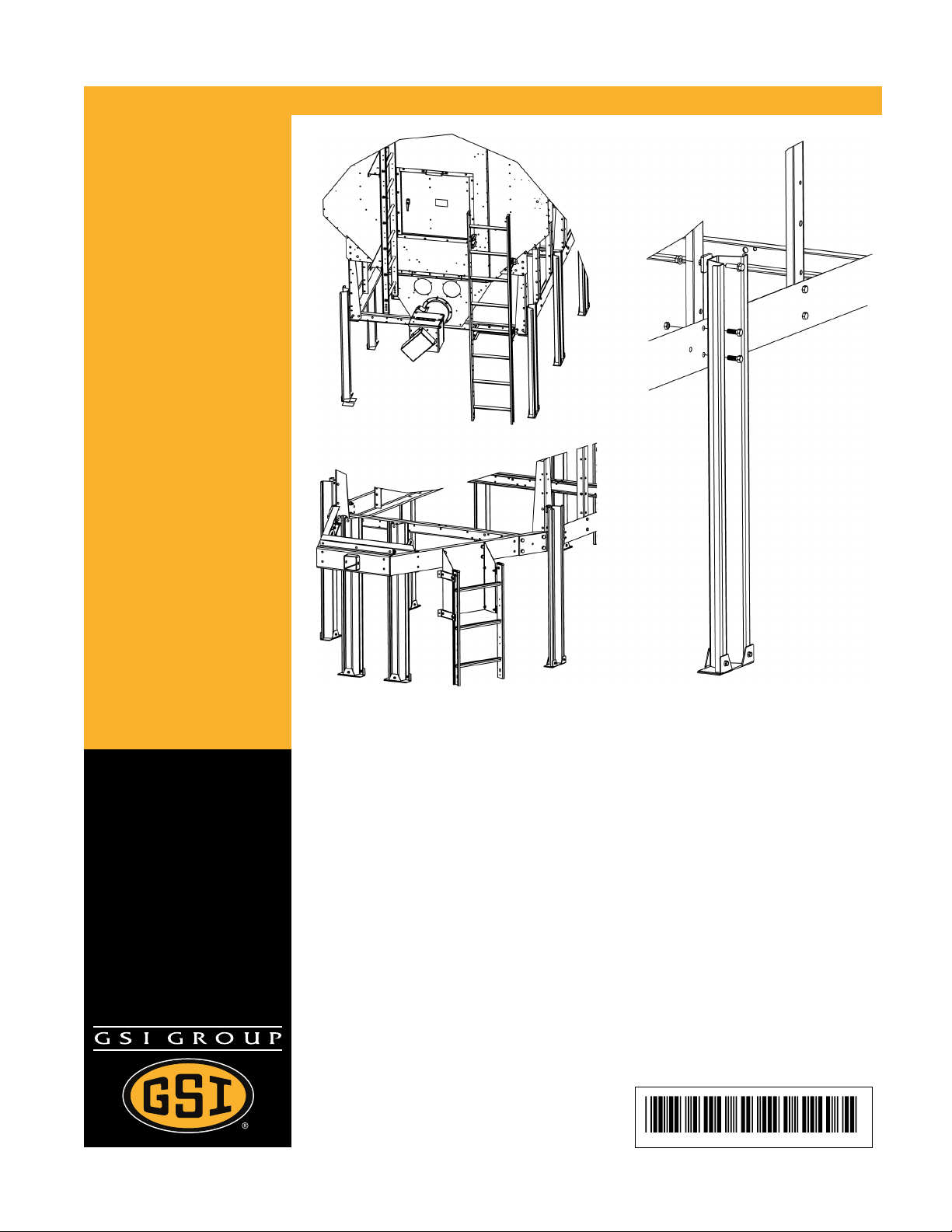
Leg Stands and Access Ladders
for Portable Dryers
Installation and Assembly Manual
PNEG-546
Date: 09-24-12
PNEG-546
Page 2

All information, illustrations, photos, and specifications in this manual are based on the latest
information available at the time of publication. The right is reserved to make changes at any
time without notice.
Page 3

Table of Contents
Contents
Chapter 1 Safety Precautions ....................................................................................................................5
Safety Guidelines ........................................................................................................................5
Cautionary Symbols ....................................................................................................................7
Chapter 2 Dryer Supports ..........................................................................................................................9
Guidelines for Supporting the Dryer with Leg Stands ......................................................................9
Leg Stand Spacing ....................................................................................................................10
Installing Front and Rear Anchor Plates....................................................................................... 11
Installing a Leg Stand to the Dryer Basket Corner......................................................................... 11
Installing a Leg Stand Along the Dryer’s Frame............................................................................ 12
Installing the Leg Stands Behind the Hitch Frame.........................................................................14
Chapter 3 Hitch Ladder ............................................................................................................................15
Hitch Ladder Packages .............................................................................................................. 15
Installing the Hitch Ladder Support Bracket to the Hitch Channel...................................................16
Installing the Ladder Standoff Bracket to the Hitch Ladder Support Bracket ....................................17
Installing the Ladder to the Ladder Standoff Brackets ................................................................... 18
Installing the End Cap to the Ladder............................................................................................18
Chapter 4 Rear Access Ladder ................................................................................................................21
Installing the Rear Ladder Support Brackets ................................................................................ 21
Installing the Ladder Standoff Brackets to the Rear Ladder Support Brackets ................................. 23
GSI Group, LLC Limited Warranty............................................................................................ 25
Page 4

NOTES
Page 5

1 Safety Precautions
Topics Covered in this Chapter
▪ Safety Guidelines
▪ Cautionary Symbols
Safety Guidelines
Safety guidelines are general-to-specific safety rules that must be respected at all times in the grain storage environment.
Our foremost concern is your safety and the safety of others associated with grain handling equipment.
This manual is to help you understand safe operating procedures and some problems that can be encountered by the operator and other personnel.
As owner and/or operator, you are responsible to know what requirements, hazards and precautions exist
and inform all personnel associated with the equipment or in the area. Safety precautions can be required
from the personnel. Avoid any alterations to the equipment, which can produce a very dangerous situation,
where SERIOUS INJURY or DEATH can occur.
This equipment shall be installed in accordance with the current installation codes and applicable regulations, which should be carefully followed in all cases. Authorities having jurisdiction must be consulted
before installations are made.
You should consider the location of the bin site relative to power line locations or electrical transmission
equipment. Contact your local power company to review your installation plan or for information concerning
required equipment clearance. Clearance of portable equipment that can be taken to the bin site must also
be reviewed and considered. Any electrical control equipment in contact with the bin must be properly
grounded and installed in accordance with National Electric Code provisions and all local codes.
This product is intended for the use of drying grain only. Any other use is a misuse of the product.
This product has sharp edges, which may cause serious injury. To avoid injury,
CAUTION
Personnel operating or working around equipment must read this manual. This manual must be delivered
with equipment to its owner. Failure to read this manual and its safety instructions is a misuse of the
equipment.
handle sharp edges with caution and always use proper protective clothing and
equipment.
Page 6
Chapter 1: Safety Precautions
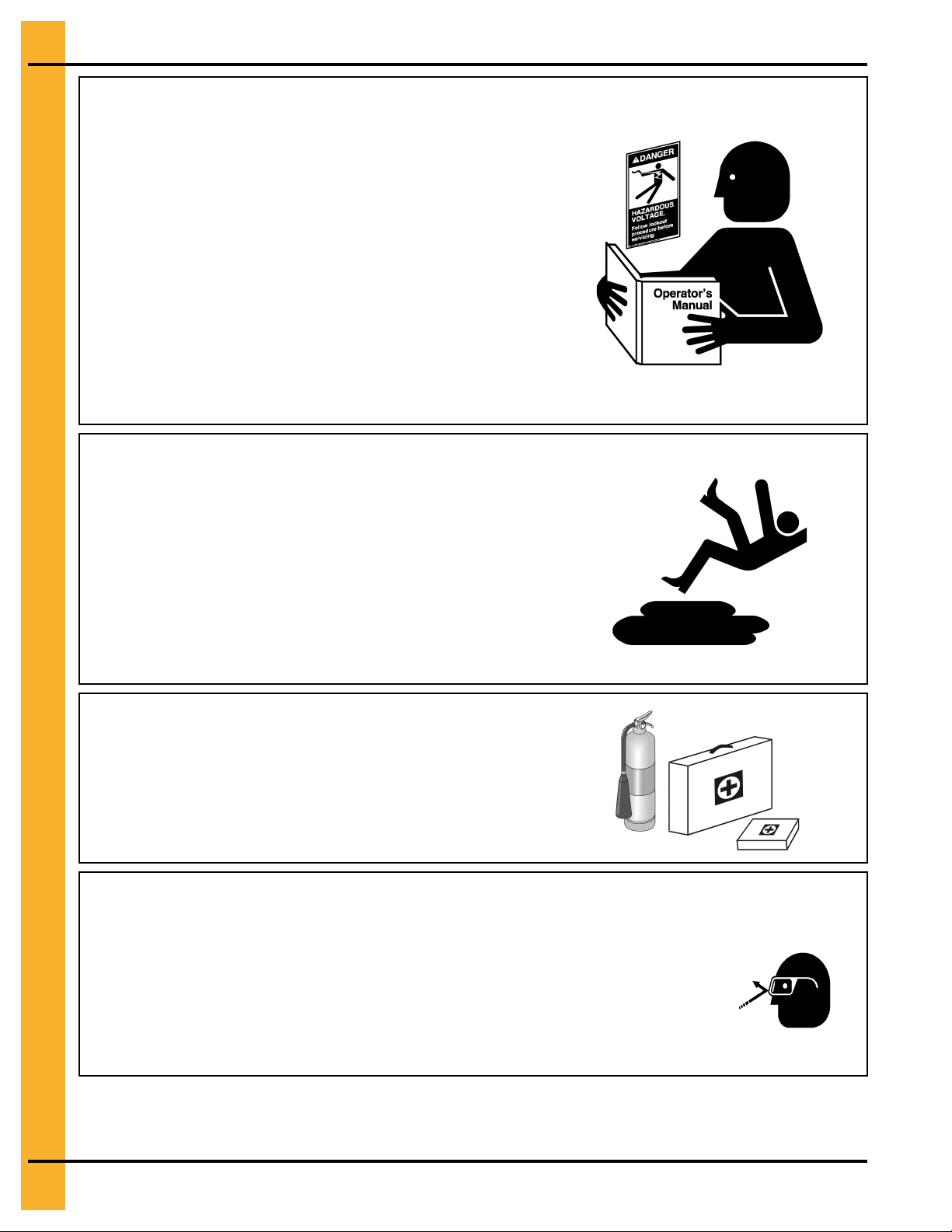
Follow Safety Instructions — Read and Understand Manual
• Carefully read all safety messages in this manual and safety
signs on your machine. Keep signs in good condition.
Replace missing or damaged safety signs. Be sure new
equipment components and repair parts include the current
safety signs. Replacement safety signs are available from
the manufacturer
• Learn how to operate the machine and how to use controls
properly. Do not let anyone operate without instruction.
• Keep your machinery in proper working condition. Unauthorized modifications to the machine can impair the function
and/or safety and affect machine life.
• If you do not understand any part of this manual or need
assistance, contact your dealer.
Practice Safe Maintenance — Maintain Equipment and Work
Area
• Understand service procedures before doing work. Keep
area clean and dry.
• Never lubricate, service, or adjust machine while it is in operation. Keep hands, feet, and clothing away from rotating
parts.
• Keep all parts in good condition and properly installed. Fix
damage immediately. Replace worn or broken parts. Remove
any built-up grease, oil, and debris.
Prepare for Emergencies — Keep Emergency Equipment
Accessible
• Be prepared if fire starts.
• Keep a first aid kit and fire extinguisher handy.
• Keep emergency numbers for doctors, ambulance service,
hospital, and fire department near your telephone.
Wear Protective Clothing
• Wear close-fitting clothing and safety equipment appropriate to the job.
• Remove all jewelry
• Tie long hair up and back.
• Wear safety glasses at all times to protect eyes from
debris.
Eye Protection
Page 7
Chapter 1: Safety Precautions
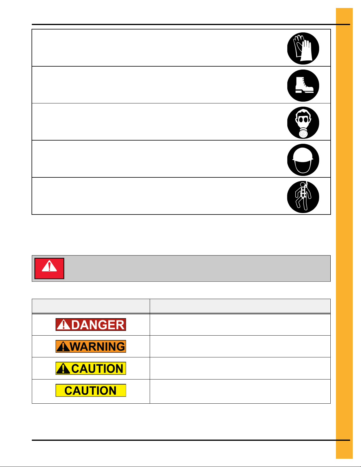
• Wear gloves to protect your hands from sharp edges on
plastic or steel parts.
• Wear steel-toed boots to help protect your feet from falling
debris. Tuck in any loose or dangling shoestrings.
• A respirator may be needed to prevent breathing potentially toxic fumes and dust.
• Wear a hard hat to help protect your head.
• Wear appropriate fall protection equipment when working
at elevations greater than 6 ft (1.8 m).
Gloves
Steel-Toed Boots
Respirator
Hard Hat
Fall Protection
Cautionary Symbols
Cautionary symbols appear in the various decals of your grain bin, and alerts the user to the potential or
imminent risk of danger.
Make sure to familiarize yourself with these symbols prior to installing, operating, or
DANGER
Table 1-1 Description of the different cautionary symbols
servicing your grain equipment. Failure to do so may lead to serious injury or death.
Symbol Description
This symbol indicates an imminently hazardous situation which, if
not avoided, will result in serious injury or death
This symbol indicates a potentially hazardous situation which, if not
avoided, may result in serious injury or death
This symbol indicates a potentially hazardous situation which, if not
avoided, may result in minor or moderate injury
This symbol indicates a potentially hazardous situation which, if not
avoided, may result in property damage
Page 8

NOTES
Page 9

2 Dryer Supports
Topics Covered in this Chapter
▪ Guidelines for Supporting the Dryer with Leg Stands
▪ Leg Stand Spacing
▪ Installing Front and Rear Anchor Plates
▪ Installing a Leg Stand to the Dryer Basket Corner
▪ Installing a Leg Stand Along the Dryer’s Frame
▪ Installing the Leg Stands Behind the Hitch Frame
Guidelines for Supporting the Dryer with Leg Stands
Before filling the dryer with grain, the dryer frame must be supported with either concrete blocks or leg
stands. Leg stands are optional and available in seven different sizes to accomodate various dryer
heights.
Leg Stand Height Options
Leg stands are optional and must be ordered separately from your dryer. If you do not have leg stands,
you must support the dryer with concrete blocks.
Figure 2-1 Leg stand heights
Part number Leg stand height
D01–0408 16 in. (406.4 mm)
D01–1046 18 in. (457.2 mm)
D01–0398 24 in. (609.6 mm)
D01–0399 30 in. (762 mm)
D01–1047 36 in. (914.4 mm)
D01–0582 42 in. (1066.8 mm)
D01–0761 48 in. (1219.2 mm)
Page 10

Chapter 2: Dryer Supports
Leg Stand Spacing
Correct leg spacing is important to adequately support the dryer during operation. Incorrect spacing might
result in unstable operating conditions.
Leg Spacing for Standard Dryers
Starting at the back corner of the dryer (A), space legs 4 ft (1.22 m) apart and move towards the front (B).
Spacing between the front legs (C) can be 2 ft (0.61 m) or 4 ft (1.22 m), depending on the length of the
dryer.
Figure 2-2 Leg spacing on a standard dryer
Leg Spacing for X-Stream Dryers
Starting at both the front and back ends of the dryer (A and B), space legs 4 ft (1.22 m) apart working
towards the center of the dryer. Spacing between center legs (C) can be 2 ft (0.61 m) or 4 ft (1.22 m),
depending on the length of the dryer.
Figure 2-3 Leg spacing on an X-Stream dryer
NOTE: The number of dryer legs varies depending on the length of the dryer.
Page 11

Chapter 2: Dryer Supports
Installing Front and Rear Anchor Plates
To secure the dryer, you must install the front and rear anchor plates to the leg stand bottoms, thereby enabling the legs to be anchored to the concrete foundation.
1. Use a flange bolt (C) and a flange nut (D) to attach the rear leg anchor plate (A) to the bottom of the
leg stand (E).
2. Position the front leg anchor plate (B) below the rear leg anchor plate (A), and use two flange bolts
(C) and flange nuts (D) to attach the anchor plate to the front of the leg stand (E).
3. Secure the leg stand (E) to the concrete foundation using concrete anchor bolts (not supplied).
Figure 2-4 Leg anchor plate assembly
Callout
A BLK-10057 Rear leg anchor plate
B
C S-6606 0.3125 in. - 18 X 3/4.75 in. zinc
D S-3611 0.3125 in. – 18 grade 2 flange nut
E D01–xxxx For leg stand, refer to Guidelines for
Part
number
BLK-10058
Description
Front leg anchor plate
grade 5 flange bolt
Supporting the Dryer with Leg
Stands, page 9.
Installing a Leg Stand to the Dryer Basket Corner
If not using concrete blocks, you must install leg stands to the dryer frame at the dryer basket corners to
support the dryer.
What You Should Know
The additional width of the hitch bracket requires the use of an extra shim to install the legs located at the
dryer frame corners.
To install a leg stand to the dryer basket corner:
1. Remove the two existing bolts and nuts from the dryer frame corner (E and F).
2. Align the holes in leg stand (H) with the holes in the dryer frame corner, and fasten in place using the
bolts and nuts that were previously removed (E and F).
3. Align the top hole in the leg stand with the hole in the basket corner leg (G).
4. Fasten the legs together using bolt (B), washer (C), two shims (A), and nut (D).
Page 12

Chapter 2: Dryer Supports
Figure 2-5 Installing a leg stand to the dryer basket corner
Callout Part number Description
A D01–1221 Shim dryer stand to dryer
B S-8856 0.50 in. - 13 X 1.75 in. zinc grade 5 flange bolt
C S-2121 0.50 in. x 1.375 in.flat washer
D S-8506 0.50 in. - 13 zinc flange nut
E S-3883 Original bolts installed on dryer (0.50 in. - 13 X 1.75 in.zinc
grade 8 HHCS bolt)
F S-6493 Original nuts installed on dryer (0.50 in. - 13 zinc grade 2
deformed lock nut)
G D01–0007 Basket corner leg
H D01–xxxx For leg stand, refer to Guidelines for Supporting the Dryer with
Leg Stands, page 9
Installing a Leg Stand Along the Dryer’s Frame
If not using concrete blocks, you must install leg stands to the dryer frame to support the dryer.
1. Remove the two bolts and nuts from the dryer frame at the location where the leg stand is to be
installed (A and B).
Page 13

Chapter 2: Dryer Supports
2. Align the holes in the leg stand (G) with the holes in the dryer frame, and fasten in place using the
bolts and nuts that were previously removed (A and B).
3. Align the top hole in the leg stand (G) with the hole in the basket leg (F).
4. Fasten the legs together using a bolt (E), shim (C), and nut (D).
5. For a secure fit, use the shim plates (H) to make any minor adjustments to the leg height.
Figure 2-6 Installing leg stands along dryer frame
Callout Part number Description
A S-3883 Original bolts installed on dryer (0.50 in. - 13 X 1.75 in. zinc
grade 8 HHCS bolt)
B S-6493 Original nuts installed on dryer (0.50 in. - 13 zinc grade 2
deformed lock nut)
C D01–1221 Shim dryer stand to dryer
NS S-2121 0.50 in.x 1.375 in. flat washer
D S-8506 0.50 in. -13 zinc flange nut
E S-8856 0.50 in. - 13 X 1.75 in.zinc grade 5 flange bolt
F D01–0007 Basket corner leg
G D01–xxxx For leg stand, refer to Guidelines for Supporting the Dryer with
Leg Stands, page 9
H FC-42077 Shim plate
Page 14

Chapter 2: Dryer Supports
Installing the Leg Stands Behind the Hitch Frame
Use leg stands behind the hitch frame to appropriately support the dryer.
1. Position the leg stands (E) behind the hitch frame, and align them with the holes in the rear hitch
cross channel (D).
2. Fasten the legs to the channel using two bolts (B), four washers (C), and two nuts (A) per each leg.
Figure 2-7 Installing leg stands to the hitch assembly
Callout
A S-8506 0.50 in. - 13 zinc flange nut
B S-8856 0.50 in. - 13 X 1.75 in. zinc grade 5 flange bolt
C S-2121 0.50 in. X 1.375 in. type A plated flat washer
D D01–2481 Rear hitch cross channel
E
Part number Description
D01–xxxx For leg stand, refer to Guidelines for Supporting the Dryer with
Leg Stands, page 9
Page 15

3 Hitch Ladder
Topics Covered in this Chapter
▪ Hitch Ladder Packages
▪ Installing the Hitch Ladder Support Bracket to the Hitch Channel
▪ Installing the Ladder Standoff Bracket to the Hitch Ladder Support Bracket
▪ Installing the Ladder to the Ladder Standoff Brackets
▪ Installing the End Cap to the Ladder
Hitch Ladder Packages
Hitch ladders are available in three different sizes. You must use the ladder package that is specific to your
dryer size.
Table 3-1 Available hitch ladder packages
Part number Description
2FOOTRF 2 foot roll formed ladder assembly used for 16,18, and 24inch dryer heights
3FOOTRF 3 foot roll formed ladder assembly used for 30 and 36 inch dryer heights
4FOOTRF 4 foot roll formed ladder assembly used for 42 and 48 inch dryer heights
Page 16

Chapter 3: Hitch Ladder
Installing the Hitch Ladder Support Bracket to the Hitch Channel
The hitch ladder is used to access the front of the dryer. It can be installed on either the right or left side of
the dryer.
1. Install the hitch ladder support bracket (A) to the center hole pattern on the hitch channel.
2. Fasten bracket (A) to the hitch channel, using flange bolts (B) and flange nuts (C).
Figure 3-1 Installing the hitch ladder support bracket to the hitch channel
Callout
A
B
C S-8506 0.50 in. - 13 zinc flange nut
Part number Description
D01–2755
S-9062 .0.50 in. - 13 X1.25 in. zinc grade 5 flange bolt
Hitch ladder support bracket
Page 17

Chapter 3: Hitch Ladder
Installing the Ladder Standoff Bracket to the Hitch Ladder Support Bracket
The ladder standoff brackets secures the ladder to the ladder support bracket, thus ensuring safe access
to the front of the dryer.
1. Align the holes in the ladder standoff brackets (B) with the holes on the side of the hitch ladder support bracket (A).
2. Fasten the four standoff brackets (B) to the hitch ladder support bracket (A) using flange bolts (C)
and flange nuts (D.)
Figure 3-2 Installing the ladder standoff bracket to the hitch ladder support bracket
Callout
A
B
C S-6606 0.3125 in. - 18 X 0.75 in. zinc grade 5 flange bolts
D
Part number Description
D01–2755
LDR-4341 Ladder standoff bracket
S-3611 0.3125 in. - 18 grade 2 flange nut
Hitch ladder support bracket
Page 18

Chapter 3: Hitch Ladder
Installing the Ladder to the Ladder Standoff Brackets
Standoff brackets are used to support the ladder along it’s vertical length and secure the ladder to the
equipment.
1. Install the carriage bolt (C) through the standoff wedge (B).
2. Hook the standoff wedge assembly (B) under the ladder edge (E).
3. Place the standoff bracket (A) onto the carriage bolt (C) and fasten in place with flange nut (D). Leave
the flange nut (D) loose to allow the ladder to slide into position before fully tightening.
4. Install all standoff brackets (A) and adjust the ladder vertically into position.
5. Fully tighten the carriage bolts (C) and flange nuts (D).
Figure 3-3 Detail of the standoff bracket
Callout
A LDR-4314 Ladder standoff bracket
B LDR-4198 Ladder standoff wedge
C S-3550 0.3125 in. x 1 in. carriage
D S-3611 0.3125 in. flange nut
Part
Number
Description
bolt
Installing the End Cap to the Ladder
The end cap helps to protects your hands from the sharp edges on the ends of the ladder.
1. Install the end caps (A) to both the right and left side of the ladder by snapping the end caps (A) into
the top of the ladder.
2. Secure the end cap (A) in place using a flange bolt (B) and flange nut (C).
Page 19

Figure 3-4 End cap assembly
Callout Part number Description
Chapter 3: Hitch Ladder
A
B S-7470 0.3125 in. - 18 X 1 in. zinc
C S-3611 0.3125 in. - 18 grade 2 flange
LDR-5011
Ladder end cap
grade 5 flange bolt
nut
Page 20

NOTES
Page 21

4 Rear Access Ladder
Topics Covered in this Chapter
▪ Installing the Rear Ladder Support Brackets
▪ Installing the Ladder Standoff Brackets to the Rear Ladder Support Brackets
Installing the Rear Ladder Support Brackets
The rear ladder support brackets attach directly to the dryer and support the ladder standoff brackets.
1. Locate the two upper rear ladder bracket installation locations (A) and remove the existing hardware
(B and C).
2. Install one upper rear ladder bracket (A) by aligning it with the bottom bolt in the door frame (B), and
fasten with the previously removed hardware.
3. Install the second upper rear bracket (A) by aligning it with the middle bolt in the gusset plate (C), and
fasten with the previously removed hardware.
4. Align the holes in the lower rear bracket (D) with the holes in the dryer frame and fasten with three
flange bolts (E) and flange nuts (F).
Page 22

Chapter 4: Rear Access Ladder
Figure 4-1 Installing the rear ladder support brackets
Callout Part number Description
A
B NA Existing hardware — bottom bolt in door frame
C NA Existing hardware — lower rear bracket
D
E
F
D01–2691
D01–2692
S-9067 0.375 in. - 16 x 0.75 in. zinc grade 5 flange bolt
S-968 0.375 in. -16 zinc grade 5 flange nut
Upper rear ladder bracket
Lower rear bracket
Page 23

Chapter 4: Rear Access Ladder
Installing the Ladder Standoff Brackets to the Rear Ladder Support Brackets
The ladder standoff brackets allow the ladder to be easily adjusted and secured to the dryer.
1. Install the ladder standoff brackets (A) to the lower rear ladder support bracket (D), using carriage
bolts (B) and flange nuts (C).
2. Install the ladder standoff brackets (A) to the upper rear ladder support brackets (E), using carriage
bolts (B) and flange nuts (C).
3. Install the ladder to standoff brackets, (see Installing the Ladder to the Ladder Standoff Brackets,
page 18).
4. Install the end caps to the ends of the ladder, (see Installing the End Cap to the Ladder, page 18).
Figure 4-2 Installing the ladder standoff bracket to rear ladder support bracket
Callout
A
B
C S-3611 0.3125 in. - 18 grade 2 flange nut
D
E
Part number Description
LDR-4341 Standoff bracket
S-3550 0.3125 in. x 1 in. carriage bolt
D01–2692
D01–2691
Lower rear ladder bracket
Upper rear ladder bracket
Page 24

NOTES
Page 25

GSI Group, LLC Limited Warranty
GSI Group, LLC Limited Warranty
The GSI Group, LLC (“GSI”) warrants products which it manufactures to be free of defects in materials and workmanship
under normal usage and conditions for a period of 12 months after sale to the original end-user or if a foreign sale, 14
months from arrival at port of discharge, whichever is earlier. The end-user’s sole remedy (and GSI’s only obligation) is to
repair or replace, at GSI’s option and expense, products that in GSI’s judgment, contain a material defect in materials or
workmanship. Expenses incurred by or on behalf of the end-user without prior written authorization from the GSI Warranty
Group shall be the sole responsibility of the end-user.
Warranty Extensions:
The Limited Warranty period is extended for the following products:
Product Warranty Period
Performer Series Direct Drive Fan Motor 3 Years
AP Fans and Flooring
Cumberland
Feeding/Watering
Systems
Grain Systems Grain Bin Structural Design
Grain Systems
Farm Fans
Zimmerman
All Fiberglass Housings
All Fiberglass Propellers
Feeder System Pan Assemblies
Feed Tubes (1-3/4" and 2.00")
Centerless Augers
Watering Nipples
Portable and Tower Dryers
Portable and Tower Dryer Frames and Internal Infrastructure †
Lifetime
Lifetime
5 Years **
10 Years *
10 Years *
10 Years *
5 Years
2 Years
5 Years
* Warranty prorated from list price:
0 to 3 years - no cost to end-user
3 to 5 years - end-user pays 25%
5 to 7 years - end-user pays 50%
7 to 10 years - end-user pays 75%
** Warranty prorated from list price:
0 to 3 years - no cost to end-user
3 to 5 years - end-user pays 50%
† Motors, burner components and
moving parts not included.
Portable dryer screens included.
Tower dryer screens not included.
GSI further warrants that the portable and tower dryer frame and basket, excluding all auger and auger drive components,
shall be free from defects in materials for a period of time beginning on the twelfth (12
and continuing until the sixtieth (60
th
) month from the date of purchase (extended warranty period). During the extended
th
) month from the date of purchase
warranty period, GSI will replace the frame or basket components that prove to be defective under normal conditions of use
without charge, excluding the labor, transportation, and/or shipping costs incurred in the performance of this extended
warranty.
Conditions and Limitations:
THERE ARE NO WARRANTIES THAT EXTEND BEYOND THE LIMITED WARRANTY DESCRIPTION SET FORTH
ABOVE. SPECIFICALLY, GSI MAKES NO FURTHER WARRANTY OF ANY KIND, EXPRESS OR IMPLIED, INCLUDING,
WITHOUT LIMITATION, WARRANTIES OF MERCHANTABILITY OR FITNESS FOR A PARTICULAR PURPOSE OR
USE IN CONNECTION WITH: (I) PRODUCT MANUFACTURED OR SOLD BY GSI OR (II) ANY ADVICE, INSTRUCTION,
RECOMMENDATION OR SUGGESTION PROVIDED BY AN AGENT, REPRESENTATIVE OR EMPLOYEE OF GSI
REGARDING OR RELATED TO THE CONFIGURATION, INSTALLATION, LAYOUT, SUITABILITY FOR A PARTICULAR
PURPOSE, OR DESIGN OF SUCH PRODUCTS.
GSI shall not be liable for any direct, indirect, incidental or consequential damages, including, without limitation, loss of
anticipated profits or benefits. The sole and exclusive remedy is set forth in the Limited Warranty, which shall not exceed
the amount paid for the product purchased. This warranty is not transferable and applies only to the original end-user. GSI
shall have no obligation or responsibility for any representations or warranties made by or on behalf of any dealer, agent or
distributor.
GSI assumes no responsibility for claims resulting from construction defects or unauthorized modifications to products
which it manufactured. Modifications to products not specifically delineated in the manual accompanying the equipment at
initial sale will void the Limited Warranty.
This Limited Warranty shall not extend to products or parts which have been damaged by negligent use, misuse, alteration,
accident or which have been improperly/inadequately maintained. This Limited Warranty extends solely to products manufactured by GSI.
Prior to installation, the end-user has the responsibility to comply with federal, state and local codes which apply to the location and installation of products manufactured or sold by GSI.
9101239_1_CR_rev7.xml (revised July 2009)
Page 26

This equipment shall be installed in accordance with the
current installation codes and applicable regulations
which should be carefully followed in all cases.
Authorities having jurisdiction should be consulted
before installations are made.
Copyright © 2012 by GSI Group
Printed in the USA
GSI Group
1004 E. Illinois St.
Assumption, IL 62510-0020
Phone: 1-217-226-4421
Fax: 1-217-226-4420
www.gsiag.com
CN #301718
 Loading...