

Page 1
Instructions
PNEG-510
Improper installation methods of the hardware may cause permanent damage and
possible breakage of the boot.
CAUTION
1004 East Illinois Street • Assumption, IL 62510 • 1-217-226-4421
HR Unloader Restrictor Adjustment
Boot and Transfer Plate Installation
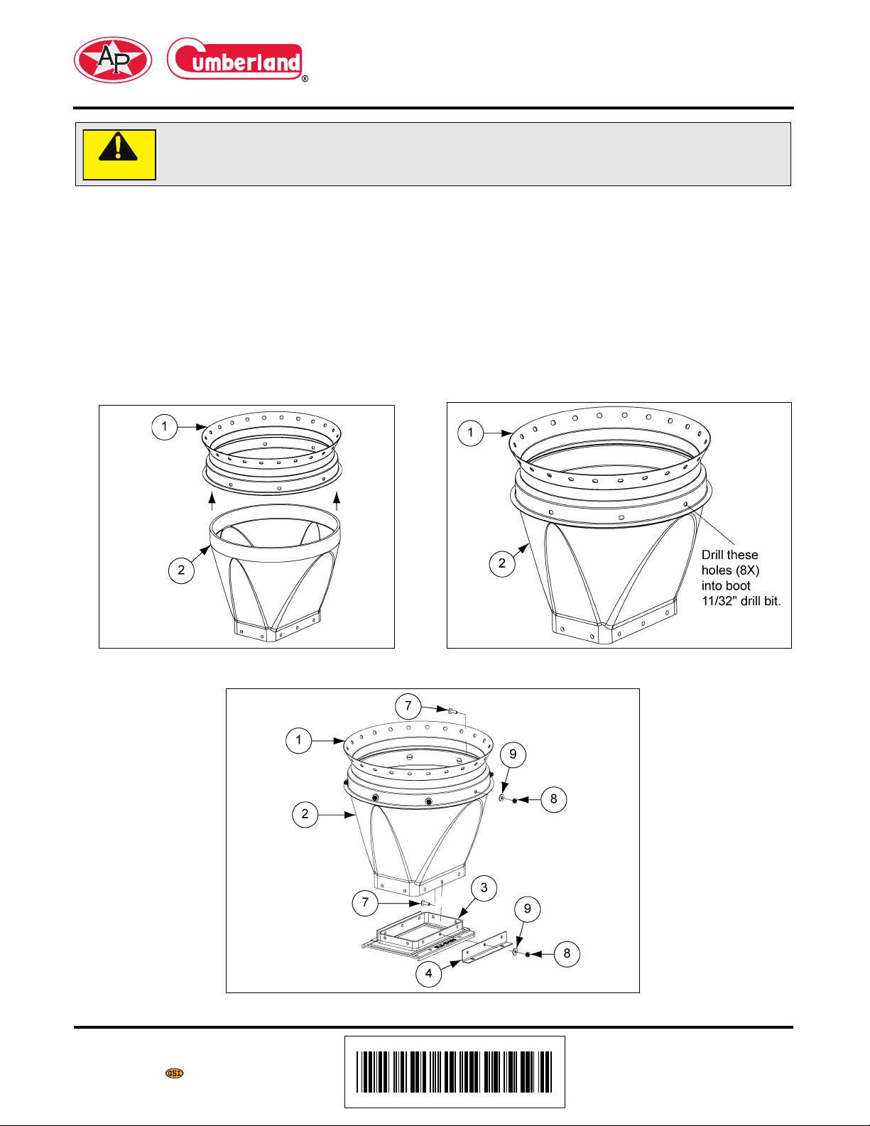
NOTE: Installation of the boot is the same whether the tank has the standard collar or the Sure-Flo
Feed Flow Control.
Slide the boot as far as possible into the tank collar or the Sure-Flo Feed Flow Control opening.
(See Figure 1.) Align the boot with the Flex-Flo System that will be installed. Using the holes in the
collars for guides, drill eight (8) 11/32" holes into the boot rim. (See Figure 2.)
Mount the boot to the collar with the hardware provided. Bolt the Transfer Plate and Unloader Braces to
the boot as shown. See Figure 3 for proper usage and assembly direction of hardware for mounting the
boot and the transfer plate. All connections should be tightened until they are “snug”.
Figure 1
Figure 3
Date: 04-28-11 PNEG-510
Printed in the U.S.A.
Copyright © 2011 by Group
www.gsiag.com
Figure 2
Page 1 of 5
Page 2
HR Unloader Restrictor Adjustment
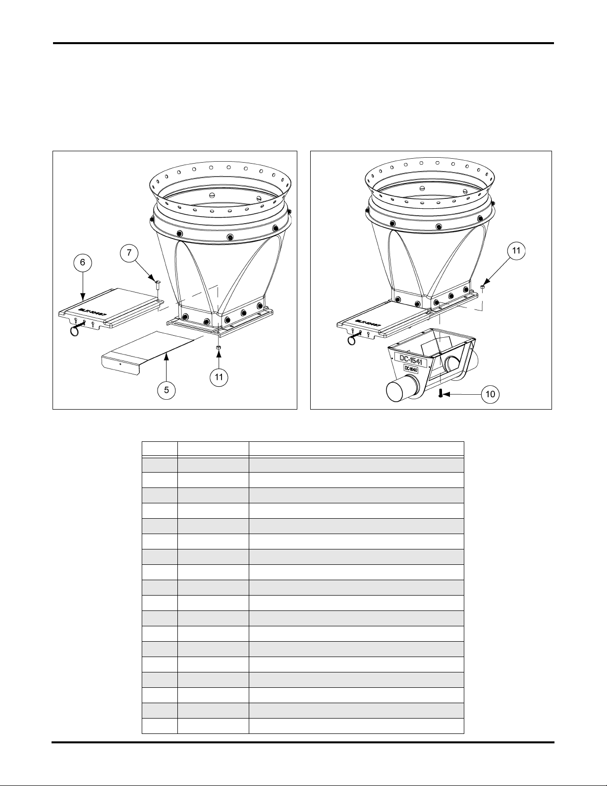
Slide Gate Installation
Insert the slide into the transfer plate. The slide must be in its operating position prior to attaching the slide
shield to the transfer plate. Use two (2) 5/16"-18 x 1" truss head tap bolts to mount the slide shield.
(See Figure 4.)
Bolt unloader to transfer plate/unloader brace assembly as shown in Figure 5. Note orientation of these
bolts. (See Figure 5.)
Figure 4 Figure 5
Ref # Part # Description
1 BLK-10488 16" 67° 16" Hopper Collar (24 Holes)
1 BLK-10489 16" 60° Hopper Collar (24 Holes)
1 BLK-11463 16" 60° Hopper Collar (27 Holes)
1 BLK-12342 16" 60° Hopper Collar (18 Holes)
2 FLX-2194 16" 30° Black Plastic Boot
2 FLX-2194C 16" 30° Clear Plastic Boot
2 FLX-2195 16" Straight Black Plastic Boot
2 FLX-2195C 16" Straight Clear Plastic Boot
2 FLX-4869 16" Double Straight Black Boot
3 BLK-10496 Transfer Plate
4 FLX-4819 Unloader Brace
5 FLX-4782 Slide Gate
6 BLK-10497 Slide Gate Shield
7 S-4336 5/16" x 1" Truss Head Machine Screw
8 S-4337 5/16"-18 Nylon Insert Nut
9 S-4338 5/16" Nylon Washer
10 S-8328 Screw, MS 5/16"-18 x 1" RHS ZN Grade 2
11 S-396 Hex Nut 5/16"-18 YDP Grade 2
Page 2 of 5 PNEG-510
Page 3

HR Unloader Restrictor Adjustment
Inspection/Clean-Out Plate Installation
Once the installation of the auger tubes and auger is complete, insert the inspection/clean-out plate
or the optional unloader switch.
The inspection/clean-out plate is to be installed per the following instructions (See Figure 6):
1. Back off both wing nuts to the stud ends.
2. Slide the plate onto the lower side of the unloader opening.
3. Move the plate first against the side of the unloader then upward toward the top of the unloader.
4. Tighten the wing nuts while holding the plate steady.
Figure 6 Clean-Out Plate Installation
PNEG-510 Page 3 of 5
Page 4

HR Unloader Restrictor Adjustment
Restrictor Adjustment
The restrictor may be adjusted to allow more feed flow. Do not modify the restrictor until the system is
completely operational and the auger has been polished by running feed through the system.
Instructions:
1. Remove the restrictor tube from the unloader.
2. Cut 1" (2.5 cm) from the restrictor. (See Figure 7.)
3. Install the restrictor and the bearing assembly into the unloader.
4. Test the feed flow.
5. If the desired feed flow rate is not attained, repeat the above procedure until the desired rate
is reached.
Figure 7 Restrictor Adjustment
Page 4 of 5 PNEG-510
Page 5

HR Unloader and Anchor Assembly
HR Unloader Restrictor Adjustment
HR Unloader
Ref # Part # Description
1 FLX-2195 16" Straight Black Plastic Boot
1 FLX-2195C 16" Straight Clear Plastic Boot
2 FLX-2194 16" 30° Black Plastic Boot
2 FLX-2194C 16" 30° Clear Plastic Boot
N/S FLX-4869 16" Double Straight Black Boot
3 BLK-11137A Transfer and Slide Gate Kit
4 404238 Iron Ball 3" Hollow - 1-1/2 #
5 FLX-4461 Clean-out Plate Assembly
6 S-4319 3-1/2" Tube Clamp
7 FLX-4648HR Anchor and Bearing Assembly
8 FLX-2605 Model HR Flex-Flo Single through Unloader Body Assembly
9 S-4443 4" Tube Clamp
10 FLX-2217 Model 220, 300, 350 Flex Seal Ring
11 FLX-3422 Neoprene Seal
12 FLX-2116HR HR Twin Unloader Body with Baffle
13 FLX-4819 Unloader Brace
PNEG-510 Page 5 of 5
 Loading...