

Page 1

Fan And Heater
Application
Guide
PNEG-501
Page 2

Page 3

Fan/Heater Application
Roof Warning, Operation & Safety................................................................................4
Safety Alert Decals........................................................................................................5
Fan Application Guide........................................................................................................6
Fan Application Guide......................................................................................................7
Fan Selection..................................................................................................................8
Aeration System Requirements.......................................................................................9
Example..............................................................................................................10
Situation..............................................................................................................11
Fan Performance Specifications..................................................................................12
Suggested Airflow Rates............................................................................................13
Static Pressure Charts....................................................................................................14
Beans w/ stirring........................................................................................................14
Corn w/ stirring......................................................................................................15
Rice w/ stirring.....................................................................................................16
Wheat w/ stirring....................................................................................................17
Barley..................................................................................................................18
Beans..................................................................................................................19
Clover..................................................................................................................20
White Popcorn.....................................................................................................21
Earcorn................................................................................................................22
Flax.....................................................................................................................23
Milo.....................................................................................................................24
Oats.....................................................................................................................25
Peanut.................................................................................................................26
Popcorn...............................................................................................................27
Rape....................................................................................................................28
Rice.....................................................................................................................29
Wheat..................................................................................................................30
Heater Application and Sizing....................................................................................31
Plenum Temperature........................................................................................................32
TABLE OF CONTENTS
3
Page 4
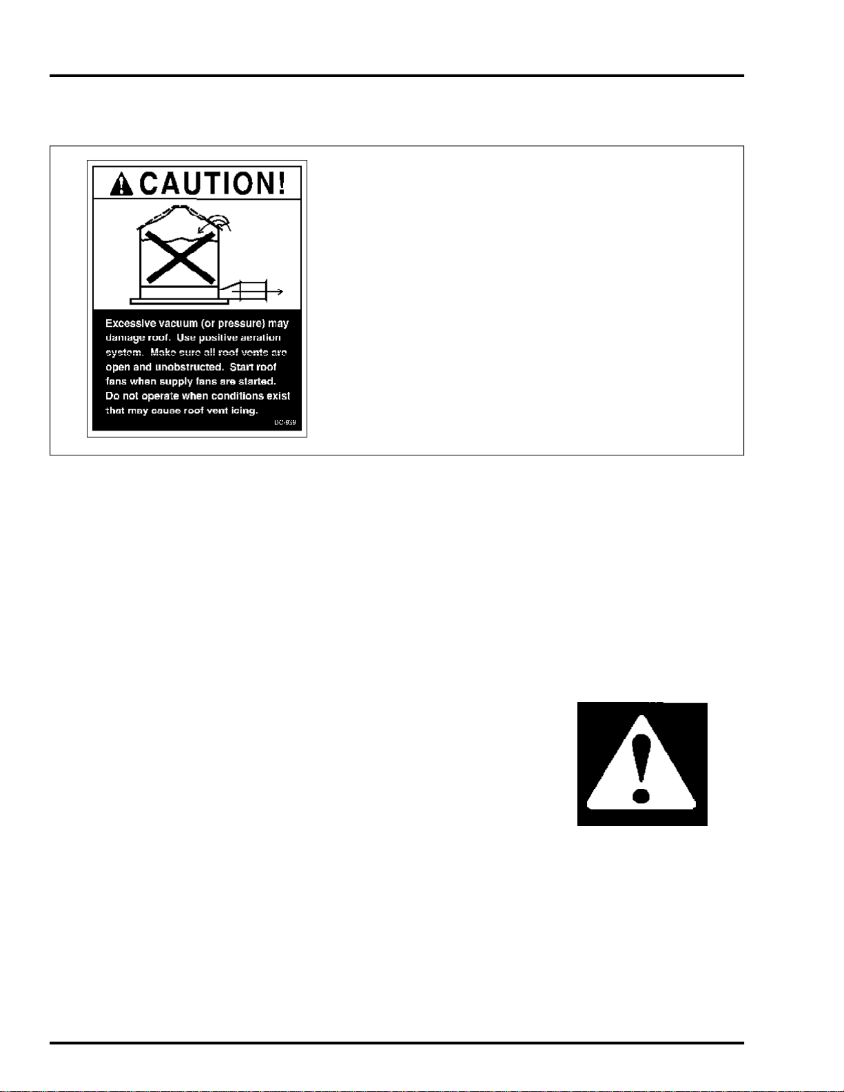
ROOF WARNING, OPERATION & SAFETY
Roof Damage Warning and Disclaimer
GSI DOES NOT WARRANT ANY ROOF DAMAGE
CAUSED BY EXCESSIVE VACUUM OR INTERNAL
PRESSURE FROM FANS OR OTHER AIR MOVING
SYSTEMS. ADEQUATE VENTILATION AND/OR
"MAKEUP AIR" DEVICES SHOULD BE PROVIDED
FOR ALL POWERED AIR HANDLING SYSTEMS.
GSI DOES NOT RECOMMEND THE USE OF DOWNWARD FLOW SYSTEMS (SUCTION). SEVERE
ROOF DAMAGE CAN RESULT FROM ANY BLOCKAGE OF AIR PASSAGES. RUNNING FANS DURING
HIGH HUMIDITY/COLD WEATHER CONDITIONS
CAN CAUSE AIR EXHAUST OR INTAKE PORTS TO
FREEZE.
Fan/Heater Application
Fuel Warning
Important! Do not use propane tanks which have previously been used for ammonia unless they
have been purged according to procedures of the National L. P. Association.
Be sure fuel supply system complies with all local codes for L. P. gas installations.
DO NOT USE FLAME FOR LEAK TESTING.
Power Warning
Be sure power is disconnected and locked out before installation!
Failure to do so may cause serious injury or death.
Important! Heater must be interlocked with fan for safe operation.
Important! Thermostat must be installed for safe operation.
Proper Use of Product
This product is intended for the use of grain drying only! Any other use is a misuse of this product.
This product has sharp edges! These sharp edges may cause serious injury. To avoid injury
handle sharp edges with caution and use proper protective clothing and equipment at all times.
Guards are removed for illustration only. All guards must be in place before and during operation.
4
Page 5
Fan/Heater Application
CAUTION! BE VERY
CAREFUL WHEN
CHECKING OUT 220V OR
460V CONTROL CIRCUIT.
SERIOUS INJURY OR
DEATH MAY OCCUR IF
PROPER PRECAUTIONS
ARE NOT TAKEN.
SAFETY ALERT DECALS
FAILURE TO INSTALL
THERMOSTAT INCREASES RISK OF FIRE IN BIN!
WARRANTIES ARE VOID ON HEATERS INSTALLED
WITHOUT THERMOSTATS.
The GSI Group, Inc. recommends contacting your local power
company, and having a representative survey your installation so the
wiring is compatible with their system, and adequate power is supplied to your unit.
Safety decals should be read
and understood by all people in
the grain handling area.
If a decal is damaged or is
missing contact:
The GSI Group, Inc.
1004 E. Illinois St.
Assumption, IL 62510
217-226-4421
A free replacement will be sent to
you.
BE SURE POWER IS
DISCONNECTED AND
LOCKED OUT BEFORE
INSTALLATION. FAILURE
TO DO SO MAY CAUSE
SERIOUS INJURY OR
DEATH
5
Page 6
FAN APPLICATION GUIDE
3500RPM Vane Axial fans are normally high performance low static pressure
fans. They are normally used for inbin drying or aeration on shorter tanks or when
low resistance grains (corn, soybeans are processed. The application should be
looked at very closely when aerating unusually tall tanks or high resistance grains
NO
Vane Axial Fans
(wheat, milo).
YES
Fan/Heater Application
NO
Inline Centrifugal Fans
3500RPM Inline Centrifugal fans are normally medium performance medium
static pressure fans. They are normally used for aeration on taller tanks or when
high resistance grains (wheat, milo) are processed. Inlines may also be used in
drying applications however care should be taken to use correct adapters when
using gas heaters with these fans. These fans are often mis-applied and sold as a
quiet drying fan when a vane axial fan of equal horsepower will most likely out
perform it. The application should be looked at very closely when aerating unusu-
ally tall tanks or high airflow resistance grains (wheat, milo).
NO
YES
MAYBE
6
Page 7
Fan/Heater Application
1750RPM Centrifugal fans are normally high performance, medium static pressure
fans. They are normally used for aeration or drying on shorter tanks or when low
resistance grains (corn, soybeans) are processed. These fans may be used with gas
heaters, either mounted on the inlet side of the fan or downwind on the outlet side.
Greater airflow is attained when the heaters are mounted downwind. Fans larger
than 30HP require a 17" tall plenum (floor) so the transition will clear. The
application should be looked at very closely when aerating unusually tall tanks or
FAN APPLICATION GUIDE
1750RPM Centrifugal Fans
high resistance grains (wheat, milo).
NO
YES
3500RPM Centrifugal Fans
3500RPM Centrifugal fans are normally medium preformance high static pressure
fans. They are normally used for aeration on taller tanks or when high resistance
grains (wheat, milo) are processed. These fans are not normally used with heaters.
Although these fans are less expensive than 1750RPM fans they are not normally
used on shallower grain depths because 1750RPM fans give much greater perfor-
mance for the horsepower at shallow depths thus less horsepower is required.
MAYBE
YES
NO
MAYBE
7
Page 8

FAN & ROOF VENT SELECTION
Fan/Heater Application
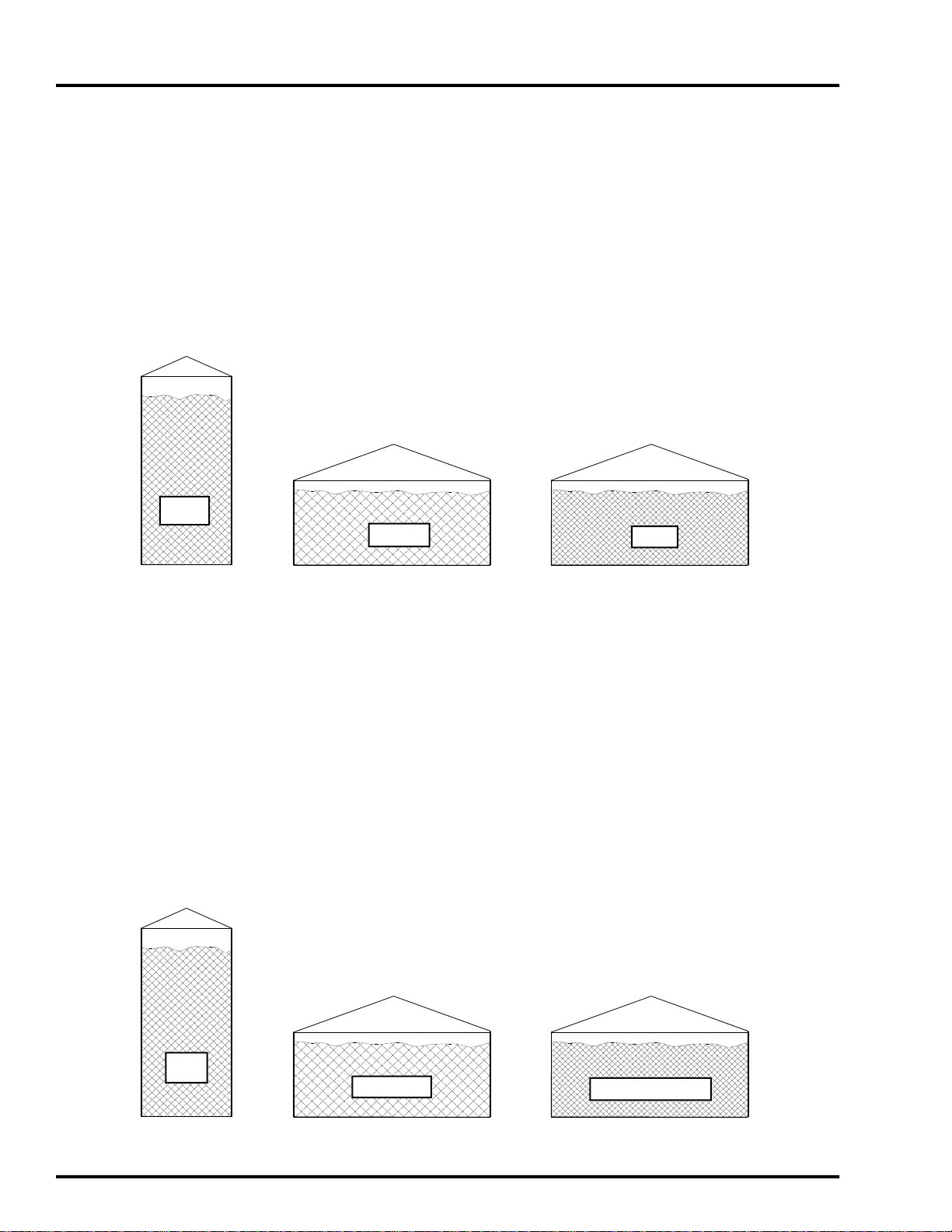
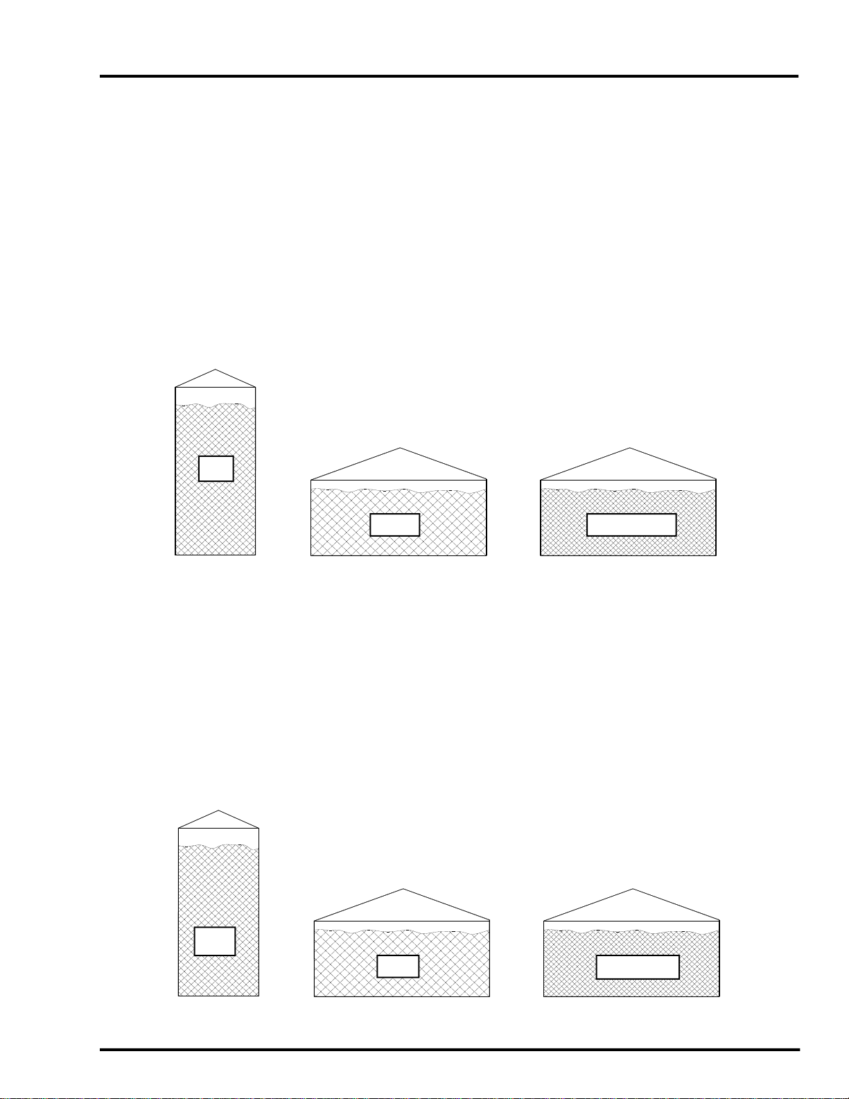
STEP 1
LEVEL FILL
PEAKED FILL
STEP 2.
Use SUGGESTED AIRFLOW RATES (page 13-30) for
desired drying or aeration conditions.
STEP 3.
For a selected grain, find the static pressure for the
corresponding AVE GRAIN DEPTH and AIRFLOW
RATE. Use the nearest height or approximate where
necessary. Where stirring machines are to be used, use
charts for stirring.
STEP 4.
BUSHELS = AVE GRAIN DEPTH (ft) x 0.6594 x
DIAMETER (ft) x DIAMETER (ft)
Since the calculation uses an average grain depth, the
capacity may vary from published sales capacities.
STEP 5.
TOTAL AIRFLOW (cfm) = AIRFLOW RATE x
BUSHELS
If more than one fan is desired for a system, divide the
TOTAL AIRFLOW by the number of fans to get the
CFM REQUIRED PER FAN for fan Selection.
STEP 6.
TABLE for vane axial or centrifugal fans, the TOTAL
. Determine the average grain depth
for a desired bin size:
-AVE GRAIN DEPTH (ft) =
EAVE HEIGHT (ft) - FLOOR HEIGHT ft)
- AVE GRAIN DEPTH (ft) =
EAVE HEIGHT (ft) + BIN DIAMETER
(ft) ÷12, Minus FLOOR HEIGHT (ft)
Select airflow rate in CFM/BU:
Using the STATIC PRESSURE
TABLES:
Determine bin capacity:
This capacity includes 5% compaction.
Find the required TOTAL AIR
FLOW in CFM:
IMPORTANT!
Using the FAN PERFORMANCE
STATIC PRESSURE from Step 3, and the CFM
PER FAN from Step 5, select the fan best
meeting the requirements. For best fan performance, a fan should run in the mid-range of is static
pressure ratings, if possible. Should excessive
static pressures be encountered, as with small grain
or very high airflows, consult GSI engineering for
the best fan choice.
NOTE:
tank aeration is in question.
Consult GSI engineering where hopper
Roof Vent Selection
STEP 7.
NUMBER ROOF VENTS = TOTAL AIRFLOW
(cfm) ÷ 1800 (cfm per vent)
If less than a full bin is intended an increased
number of roof vents will be necessary. The same
fan will produce a greater airflow when the bin is
less than full, due to less resistance from the grain.
An inadequate number of vents may have two
undesired effects
1) adding to the static pressure causing poor
fan performance and less air through the grain than
intended, and
2) possible structural damage to the roof
due to this increased pressure. Ideally, there should
be near zero static pressure in the space between the
grain and the roof.
A good estimate of vent numbers particularly in drying situations, would be using the CFM
from the FAN PERFORMANCE TABLE at onehalf the static pressure anticipated. This new value
should be divided by 1800 CFM/VENT.
Determine MINIMUM number of
roof vents:
8
Page 9

Fan/Heater Application
AERATION SYSTEM REQUIREMENTS
Full perforated floors are recommended in most DRYING situations. Floor
gauges
the grain load for a particular bin size. Please
inquire
(formed in concrete) systems are recommended when aeration only is desired. The
two most important aspects of aeration design
are the total perforated floor area and the
entrance duct cross-sectional area. Floors
should be sized for a maximum intended
airflow rate. To add larger fans or bin rings at
a later date may result in less than satisfactory
aeration performance.
mum requirement check for potential designs.
GSI floor designs will meet these requirements and be optimised for the best results.
STEP 8.
from
PERFORATED AREA (sq ft) = TOTAL
AIRFLOW ÷ 30cfm/sq ft.
and support spacing are dependent on
as to exact specifications. Flush floor
These steps are intended as a mini-
Determine MINIMUM re
quired perforated floor area
using TOTAL AIRFLOW
step 5.
STEP 9.
sectional area of air supply duct.
SUPPLY DUCT AREA (sq ft) = TOTAL
AIRFLOW ÷ 2000 cfm/sq ft
If more than one fan is used divide the
area by the number of fans. This is now the
area of each entrance tunnel.
To determine the inside width of the
supply ducts use the following formula. For
convenience it may be necessary to increase
this value to meet transition widths or "whole"
dimensions.
INSIDE DIMENSION OF SUPPLY DUCT
(ft) = SUPPLY DUCT AREA (sq ft) ÷
DESIRED TUNNEL DEPTH (ft)
STEP 10.
tween bin wall and nearest duct =
GRAIN DEPTH ÷ 4*
STEP 11.
tween ducts = AVE GRAIN DEPTH ÷ 2*
* These are starting values ONLY. Adequate
distribution of ducts may require smaller
distances.
Determine MINIMUM cross-
IMPORTANT!
MAXIMUM distance be-
AVE
MAXIMUM distance be-
9
Page 10

EXAMPLES
Fan/Heater Application
SITUATION:
1.
2.
3.
4.
5.
6.
On farm aeration of dry soybeans. 42" diameter, 9 rings, NSL series farm bin
with 24" eave height. A flush floor aeration system with one fan will be used.
AVE GRAIN DEPTH, peaked = 24' + (42' /12) = 27.5'
Select 1/10 CFM/BU aeration rate for beans
From the STATIC PRESSURE TABLE for BEANS at 28' (use the next
higher value or approximate) and 1/10 cfm/bu the static pressure is .91" of
water.
.91" water column
Bin capacity, BUSHELS
27.5' x 0.6594 x 42' x 42' = 31988 BUSHELS
Required TOTAL AIRFLOW, CFM
0.1 cfm/bu x 31988 bu = 3199 CFM
From the FAN PERFORMANCE TABLE for vane axial fans, at 1" (0.91")
static pressure and 3500 cfm (closest to 3199 cfm), the appropriate fan would
be a 1.5hp-18"
7.
8.
9.
10.
Number of ROOF VENTS
3500 CFM ÷ 1800 cfm/vent = 1.94, therefore 2 vents
PERFORATED AREA of floor, sq ft
3199 cfm ÷ 30 cfm/sq ft = 106.6 sq ft, minimum
SUPPLY DUCT AREA, sq ft
3199 cfm ÷ 2000 cfm/sq ft =1.60 sq ft, minimum
ID of supply duct for 12" deep tunnel = 1.6 sq ft ÷ 1.0 ft = 1.6 ft or 1.8"
Maximum distance between ducts and binwall = 27.5' ÷ 4 = 6.9'
10
Page 11

Fan/Heater Application
SITUATION
SITUATION:
1.
2.
3.
4.
5.
6. From the FAN PERFORMANCE TABLE for van axial fans, at 3.58" static
On farm in-bin drying of corn, 24' diameter, 6 ring, FCDL series farm bin with
22' eave height. Tank will be layer filled to level full. The drying systems
will consist of a full floor with 12" plenum, stirring device, one fan and heater.
AVE GRAIN DEPTH, level = (6 rings x 3.67) - 1 (floor) - 2 (stirring
device) = 19'.
Select 1 CFM/BU for heated air drying of corn.
From the STATIC PRESSURE TABLE for corn at 19' and 1cfm/bu the
static pressure is 3.58" of water.
3.58" water column
Bin operating capacity, BUSHELS
19' x 0.6594 x 24 x 24 = 7216
Required TOTAL AIRFLOW, CFM
1 cfm/bu x 7216 bu = 7216 CFM
pressure (4" on table) and 7216 cfm (10250 on table), the best choice would
be one 15 hp 26" fan.
7.
*
Number of ROOF VENTS
10250 cfm ÷ 1800 cfm/vent = 5.6, therefore 6 vents
NOTE!
Two fan/heater sets may be necessary to meet temperature requirements.
Two fan/heater sets may also be necessary to provide even air/heat distribution
when recirculating devices are in use.
It may be desired to increase the number of roof vents in a
drying situation to account for layers or batches as the effective
airflow will increase. In this example 8 vents should
accommodate the airflow at one-half the expected pressure:
12700÷1800 = 7
11
Page 12

CF-333000
2750
2450
2150
1750
800
CF-554900
4450
4000
3500
2900
1500
CF-7.5
7.5
5000
4700
4500
4200
3900
3700
3250
2300
CF-10
10
6650
6300
5900
5600
5300
4900
4300
3000
CF-15
15
10100
9500
9000
8400
7900
7400
6600
4600
CF-20
20
9400
9100
8800
8500
8200
8000
7400
6800
6500
5900
4000
CF-30
30
13200
12800
12400
11900
11500
10900
10400
9800
9100
8300
6000
CF-40
40
19000
18400
17750
17125
16500
15750
15000
14125
13125
12000
9000
CF-50
50
21600
21100
20500
19750
19000
18400
17600
16800
16000
15000
13500
11500
CF-336000
5500
5000
4500
4000
2200
CF-558750
8200
7300
6750
6100
5350
CF-7.5
7.5
12200
11600
10800
10000
9100
8000
CF-10
10
13450
12800
12050
11350
10700
9950
9000
7250
CF-15
15
17000
16000
15200
14400
13400
12200
10800
9200
CF-20
20
20500
19500
19000
18000
17000
16500
15750
14400
13300
CF-25
25
24000
23750
22750
21750
21000
20000
19000
17750
16000
12500
CF-30
30
28100
26900
25600
24600
23600
22500
21000
20100
19700
17800
16000
11500
CF-40
40
32750
31750
30750
29750
28750
27750
26750
25750
24250
22750
20250
15000
*CF-30D
30
32000
30500
29500
28000
27000
26000
25500
23000
20500
16500
*CF-40D
40
41000
39000
38000
37000
35000
33500
32000
30000
27000
24000
*CF-50D
50
49500
47500
45500
43500
42000
40000
38000
35500
32000
25000
FAN PERFORMANCE SPECIFICATIONS
STATIC PRESSURE IN INCHES
VANE AXIAL FANS
Fan/Heater Application
MODEL NO
AF-.75
AF-12
AF-14
AF-1.5
AF-3
AF-7
AF-10
AF-156
AF-158
MODEL NO
ILC-1.5
ILC-318
ILC-324
ILC-7
ILC-10
ILC-15
MODEL NO
H.P
1.5
H.P
3/4
1
1
3
7
10
15
15
FAN DIA
12"
12"
14"
18"
18"
24"
24"
26"
28"
0.0 1.0 2.0 3.0 4.0
2050 1050 500
2000 1100 650
3200 1850 1200
4650 3600 2300 1050
6300 5200 3700 2000 700
12750 11200 9500 7200 3600 950
13600 12300 10900 8900 5250
17000 15350 13700
19500 18000 16400
250
500
12000
14500
INLINE CENTRIFUGAL FANS
STATIC PRESSURE IN INCHES
H.P
1.5
3
3
7.0
10
15
FAN DIA
18"
18"
24"
24"
28"
28"
0.0 1.0 2.0
2650 2450 2300
4550 4300 4000
5000 4725 4450
5400 5150 4900
6150 5950 5800
7950 7700 7500
3.0
4.0 5.0 6.0 7.0 8.0 9.0
2100
1850 1500
3750
3500 3100 2700
4200
3950 3600 3200
4650
4400 4100 3800
5600
5450 5250 5050
7250
7000 6800 6500
1750 RPM CENTRIFUGAL FANS
STATIC PRESSURE IN INCHES
0.0 1.0 2.0 3.0 4.0 5.0 6.0 7.0 8.0 9.0
5.0
3150
9500
12400
2900
3400
4850
6250
6400
9700
4650 4400 4200 3900
6000 5700 5400 5050
6.0
4500
6400
10.0 11.0
10.0 11.0
*
DOUBLE INLET FAN.
MODEL NO
H.P
12
3500 RPM CENTRIFUGAL FANS
STATIC PRESSURE IN INCHES
0.0 2.0 4.0 6.0 8.0
10.0 12.0 14.0 16.0 18.0 20.0 22.0
Page 13

Fan/Heater Application
SUGGESTED AIRFLOW RATES
Aeration
This ventilation of stored grain to maintain
uniform moisture and temperature, uses low
airflow rates and unheated air. The lowest
rates are for dry grain and higher rates are for
higher moisture contents.
Corn
Wheat
Beans
Rice
1/10
1/13
1/10
1/10
to 1/5cfm/bu
to 1/8
to 1/7
to 1/7
cfm/bu
cfm/bu
cfm/bu
Dryeration and Cooling
Natural unheated air used to cool heated grain
and/or take out remaining few moisture points.
1/5
to 1/2
cfm/bu
Wet Holding
Higher airflow rate for maintaining wet grain
for short periods of time, generally one days'
conditioning capacity or no longer than the
recommended SAFE STORAGE TIME.
1/2
USE MAXIMUM BIN CAPACITY
TO SIZE FANS FOR APPLICATIONS IN
THIS COLUMN
to 1 cfm/bu
NOTE:
Natural Air Drying
Unheated air used on low moisture harvested
grain to remove remaining moisture points,
use layer method or full bin depending on
initial moisture, the airflow rate selected will
depend on geographic location and prevailing
weather conditions.
1 1/2
to 2 1/2cfm/bu
Low temperature Drying
5 to 20 degree F temperature rise, high airflow
rates, equilbrium drying system generally
employed with layer or full bin, stirring device
suggested.
1
to
2cfm/bu
High Temperature Drying
120-160 degree F plenum temperatures, high
airflow rates, batch or layers recommended
with stirring devices.
3/4
USE 1/2 TO 3/4 BIN CAPACITY TO SIZE
FANS FOR APPLICATION IN THIS
COLUMN. THIS WILL AVOID
UNREASONABLE FAN SIZES.
to
NOTE:
1 1/2cfm/bu
13
Page 14

PRESSURE CHART
321
3/4
1/2
1/3
1/4
1/5
1/7
1/10
1/15
1/20
2
0.55
0.53
0.52
0.51
0.5140.74
0.65
0.06
0.55
0.53
0.52
0.51
0.51
0.51
0.5161.11
0.86
0.66
0.61
0.57
0.55
0.53
0.53
0.52
0.51
0.51
0.5181.71
1.20
0.79
0.71
0.63
0.58
0.56
0.55
0.53
0.52
0.52
0.51102.56
1.68
0.98
0.84
0.71
0.63
0.60
0.58
0.55
0.54
0.52
0.52123.70
2.31
1.23
1.01
0.81
0.70
0.64
0.61
0.58
0.55
0.54
0.53145.17
3.12
1.53
1.22
0.94
0.77
0.70
0.66
0.61
0.57
0.55
0.54167.00
4.11
1.90
1.47
1.09
0.87
0.76
0.71
0.64
0.60
0.56
0.55189.23
5.30
2.34
1.77
1.26
0.97
0.84
0.76
0.68
0.62
0.58
0.562011.87
6.72
2.86
2.11
1.47
1.09
0.92
0.83
0.73
0.66
0.60
0.582214.96
8.36
3.45
2.51
1.70
1.23
1.02
0.90
0.78
0.69
0.62
0.592418.53
10.26
4.12
2.96
1.95
1.38
1.13
0.99
0.83
0.73
0.65
0.612612.41
4.88
3.46
2.24
1.55
1.25
1.08
0.90
0.77
0.67
0.632814.84
5.73
4.02
2.57
1.74
1.38
1.18
0.96
0.81
0.70
0.653017.55
6.68
4.64
2.92
1.95
1.52
1.29
1.04
0.86
0.73
0.67327.72
5.33
3.31
2.17
1.68
1.40
1.11
0.91
0.77
0.70348.86
6.08
3.73
2.42
1.85
1.53
1.20
0.97
0.80
0.723610.11
6.89
4.19
2.68
2.03
1.67
1.29
1.03
0.84
0.753811.47
7.78
4.68
2.96
2.22
1.82
1.39
1.09
0.88
0.784012.94
8.73
5.21
3.27
2.43
1.97
1.49
1.16
0.92
0.814214.52
9.76
5.78
3.59
2.65
2.14
1.60
1.23
0.97
0.844416.23
10.87
6.40
3.94
2.89
2.32
1.72
1.31
1.02
0.884618.06
12.05
7.05
4.31
3.14
2.51
1.84
1.39
1.07
0.914820.01
13.31
7.74
4.70
3.41
2.70
1.97
1.47
1.12
0.955014.65
8.48
5.12
3.69
2.91
2.11
1.56
1.17
0.995216.08
9.26
5.56
3.99
3.14
2.25
1.66
1.23
1.035417.60
10.09
6.02
4.30
3.37
2.41
1.75
1.29
1.085619.20
10.96
6.51
4.63
3.61
2.56
1.86
1.36
1.125811.88
7.02
4.98
3.87
2.73
1.96
1.42
1.176012.85
7.56
5.34
4.14
2.90
2.07
1.49
1.226213.87
8.12
5.72
4.42
3.08
2.19
1.56
1.276414.94
8.71
6.11
4.71
3.27
2.31
1.64
1.336616.05
9.33
6.52
5.01
3.47
2.44
1.71
1.386817.22
9.98
6.95
5.33
3.67
2.57
1.79
1.447018.45
10.65
7.40
5.66
3.88
2.70
1.88
1.507219.72
11.35
7.87
6.01
4.10
2.84
1.96
1.567412.08
8.36
6.36
4.33
2.98
2.05
1.627612.84
8.86
6.73
4.57
3.13
2.14
1.697813.63
9.38
7.12
4.81
3.29
2.23
1.758014.45
9.93
7.51
5.07
3.45
2.33
1.828215.29
10.49
7.92
5.33
3.61
2.43
1.898416.17
11.07
8.35
5.60
3.78
2.53
1.978617.09
11.67
8.79
5.88
3.96
2.64
2.048818.03
12.29
9.24
6.16
4.14
2.75
2.129019.00
12.93
9.71
6.46
4.32
2.86
2.209220.01
13.60
10.19
6.77
4.51
2.98
2.289414.28
10.69
7.08
4.71
3.09
2.369614.99
11.21
7.40
4.91
3.22
2.459815.71
11.74
7.74
5.12
3.34
2.54
100
16.46
12.28
8.08
5.33
3.47
2.63
.50" Water Column have been Added To Static Pressure to Account for System Loss
Static Pressures are Calculated Using a 1.15 Factor Applied to Shedd's Data
FEET
STATIC PRESSURE CHART FOR BEANS (W/STIRRING)
GRAIN
DEPTH
Fan/Heater Application
Static Pressure (inches of water column)
Airflow Rate (cfm per bushel)
14
Page 15

Fan/Heater Application
321
3/4
1/2
1/3
1/4
1/5
1/7
1/10
1/15
1/20
2
0.56
0.54
0.52
0.51
0.51
0.5140.80
0.68
0.58
0.55
0.53
0.52
0.52
0.51
0.51
0.5161.29
0.95
0.69
0.63
0.58
0.55
0.54
0.53
0.52
0.51
0.51
0.5182.10
1.40
0.86
0.75
0.65
0.60
0.57
0.55
0.54
0.53
0.52
0.51103.28
2.04
1.09
0.91
0.75
0.65
0.61
0.59
0.56
0.54
0.53
0.52124.90
2.90
1.41
1.12
0.87
0.73
0.66
0.63
0.59
0.56
0.54
0.53147.00
4.02
1.81
1.39
1.03
0.82
0.73
0.68
0.62
0.58
0.55
0.54169.63
5.41
2.30
1.71
1.21
0.93
0.80
0.73
0.66
0.61
0.57
0.551812.86
7.10
2.88
2.10
1.43
1.06
0.89
0.80
0.71
0.64
0.59
0.572016.72
9.11
3.58
2.55
1.69
1.21
1.00
0.88
0.76
0.67
0.61
0.582211.47
4.38
3.08
1.98
1.37
1.11
0.97
0.82
0.71
0.64
0.602414.20
5.31
3.68
2.32
1.57
1.24
1.07
0.88
0.75
0.66
0.622617.32
6.35
4.36
2.69
1.78
1.39
1.18
0.95
0.80
0.69
0.64287.53
5.12
3.11
2.02
1.55
1.30
1.03
0.85
0.72
0.66308.85
5.97
3.58
2.28
1.73
1.43
1.12
0.91
0.76
0.693210.31
6.91
4.09
2.57
1.92
1.57
1.21
0.97
0.80
0.723411.92
7.94
4.66
2.88
2.13
1.73
1.32
1.03
0.84
0.753613.69
9.07
5.27
3.22
2.36
1.90
1.42
1.11
0.88
0.783815.62
10.30
5.93
3.59
2.61
2.08
1.54
1.18
0.93
0.814017.72
11.63
6.65
3.99
2.88
2.28
1.67
1.26
0.98
0.854219.99
13.08
7.43
4.42
3.16
2.49
1.80
1.35
1.03
0.884414.63
8.27
4.87
3.47
2.71
1.95
1.44
1.08
0.924616.30
9.16
5.36
3.79
2.95
2.10
1.53
1.14
0.964818.09
10.11
5.88
4.13
3.20
2.26
1.63
1.20
1.015019.99
11.13
6.44
4.50
3.47
2.43
1.74
1.27
1.055212.21
7.02
4.89
3.75
2.61
1.85
1.34
1.105413.36
7.64
5.30
4.05
2.80
1.97
1.41
1.155614.57
8.30
5.73
4.37
2.99
2.09
1.48
1.205815.85
8.99
6.18
4.70
3.20
2.22
1.56
1.266017.20
9.72
6.66
5.04
3.42
2.36
1.64
1.326218.63
10.48
7.16
5.41
3.65
2.50
1.73
1.386420.13
11.29
7.69
5.79
3.89
2.65
1.81
1.446612.13
8.24
6.18
4.13
2.80
1.90
1.506813.01
8.81
6.60
4.39
2.96
2.00
1.577013.93
9.41
7.03
4.66
3.13
2.10
1.647214.90
10.04
7.49
4.94
3.30
2.20
1.717415.90
10.69
7.96
5.24
3.48
2.31
1.787616.95
11.37
8.45
5.54
3.67
2.42
1.867818.04
12.08
8.95
5.85
3.86
2.53
1.948019.17
12.81
9.48
6.18
4.06
2.65
2.028220.35
13.57
10.03
6.52
4.27
2.77
2.118414.36
10.60
6.87
4.48
2.89
2.198615.18
11.18
7.23
4.70
3.02
2.288816.03
11.79
7.60
4.93
3.15
2.379016.91
12.42
7.99
5.16
3.29
2.479217.82
13.07
8.39
5.40
3.43
2.579418.75
13.74
8.80
5.65
3.58
2.679619.72
14.43
9.22
5.91
3.72
2.779815.15
9.66
6.17
3.88
2.87
100
15.88
10.11
6.44
4.03
2.98
.50" Water Column have been Added To Static Pressure to Account for System Loss
Static Pressures are Calculated Using a 1.15 Factor Applied to Shedd's Data
STATIC PRESSURE CHART FOR CORN (W/STIRRING)
GRAIN
DEPTH
FEET
PRESSURE CHART
Static Pressure (inches of water column)
Airflow Rate (cfm per bushel)
15
Page 16

PRESSURE CHART
321
3/4
1/2
1/3
1/4
1/5
1/7
1/10
1/15
1/20
2
0.64
0.59
0.54
0.53
0.52
0.51
0.51
0.51
0.5141.14
0.89
0.68
0.63
0.58
0.56
0.54
0.53
0.52
0.52
0.51
0.5162.09
1.45
0.92
0.80
0.70
0.63
0.59
0.57
0.55
0.54
0.52
0.5283.59
2.32
1.28
1.06
0.86
0.73
0.67
0.63
0.59
0.57
0.54
0.53105.72
3.53
1.77
1.41
1.07
0.86
0.77
0.71
0.65
0.60
0.57
0.55128.57
5.13
2.41
1.85
1.34
1.03
0.89
0.81
0.72
0.65
0.60
0.571412.22
7.15
3.19
2.39
1.67
1.24
1.04
0.92
0.80
0.70
0.63
0.601616.73
9.63
4.14
3.04
2.06
1.48
1.21
1.06
0.89
0.77
0.68
0.631812.61
5.26
3.81
2.52
1.76
1.41
1.21
1.00
0.84
0.72
0.672016.11
6.56
4.69
3.05
2.08
1.64
1.39
1.12
0.92
0.78
0.712220.18
8.06
5.70
3.64
2.44
1.90
1.59
1.25
1.01
0.84
0.75249.76
6.85
4.31
2.84
2.18
1.81
1.40
1.12
0.90
0.802611.67
8.13
5.06
3.29
2.50
2.05
1.57
1.23
0.97
0.852813.80
9.55
5.88
3.78
2.84
2.31
1.75
1.35
1.05
0.913016.16
11.12
6.79
4.31
3.22
2.60
1.94
1.48
1.13
0.973218.76
12.85
7.78
4.90
3.63
2.91
2.15
1.62
1.22
1.043414.73
8.86
5.53
4.07
3.25
2.38
1.77
1.32
1.113616.78
10.02
6.21
4.54
3.61
2.62
1.93
1.42
1.183818.99
11.28
6.94
5.05
4.00
2.88
2.10
1.53
1.264012.63
7.73
5.59
4.41
3.16
2.28
1.65
1.354214.08
8.56
6.17
4.85
3.45
2.48
1.77
1.444415.63
9.46
6.78
5.31
3.76
2.68
1.90
1.534617.27
10.40
7.44
5.80
4.08
2.89
2.04
1.634819.02
11.41
8.12
6.32
4.42
3.12
2.18
1.735012.47
8.85
6.86
4.79
3.35
2.33
1.845213.59
9.62
7.44
5.16
3.60
2.48
1.955414.77
10.42
8.04
5.56
3.86
2.64
2.075616.01
11.27
8.67
5.98
4.13
2.81
2.195817.31
12.15
9.34
6.41
4.41
2.99
2.326018.67
13.08
10.03
6.86
4.71
3.17
2.466220.10
14.05
10.75
7.34
5.01
3.36
2.596415.06
11.51
7.83
5.33
3.56
2.746616.11
12.29
8.34
5.66
3.77
2.886817.21
13.11
8.87
6.00
3.98
3.047018.36
13.96
9.42
6.36
4.20
3.207219.54
14.84
9.99
6.73
4.43
3.367415.75
10.58
7.11
4.66
3.537616.70
11.20
7.50
4.90
3.707817.68
11.83
7.90
5.15
3.888018.70
12.48
8.32
5.41
4.078219.75
13.16
8.75
5.68
4.268413.86
9.20
5.95
4.458614.58
9.65
6.23
4.658815.32
10.13
6.52
4.869016.08
10.61
6.81
5.079216.87
11.11
7.12
5.299417.68
11.62
7.43
5.519618.51
12.15
7.75
5.749819.36
12.68
8.08
5.97
100
20.24
13.24
8.41
6.21
.50" Water Column have been Added To Static Pressure to Account for System Loss
Static Pressures are Calculated Using a 1.15 Factor Applied to Shedd's Data
STATIC PRESSURE CHART FOR RICE (W/ STIRRING)
GRAIN
DEPTH
FEET
Fan/Heater Application
Static Pressure (inches of water column)
Airflow Rate (cfm per bushel)
16
Page 17

Fan/Heater Application
321
3/4
1/2
1/3
1/4
1/5
1/7
1/10
1/15
1/20
2
0.73
0.65
0.57
0.55
0.53
0.52
0.52
0.51
0.51
0.5141.50
1.13
0.79
0.72
0.64
0.59
0.57
0.56
0.54
0.53
0.52
0.5162.94
2.00
1.18
1.00
0.82
0.71
0.66
0.63
0.59
0.56
0.54
0.5385.16
3.32
1.75
1.41
1.09
0.88
0.78
0.72
0.66
0.61
0.57
0.55108.27
5.13
2.52
1.96
1.43
1.10
0.95
0.85
0.75
0.67
0.61
0.591212.37
7.49
3.50
2.65
1.87
1.38
1.15
1.01
0.86
0.75
0.67
0.621417.56
10.45
4.70
3.50
2.39
1.71
1.39
1.20
1.00
0.84
0.73
0.671614.04
6.14
4.50
3.01
2.10
1.67
1.43
1.15
0.95
0.80
0.721818.31
7.82
5.67
3.73
2.55
2.00
1.68
1.33
1.07
0.88
0.78209.77
7.02
4.55
3.06
2.37
1.97
1.53
1.21
0.97
0.852211.98
8.54
5.47
3.63
2.78
2.29
1.75
1.36
1.06
0.922414.49
10.26
6.50
4.26
3.23
2.64
1.99
1.53
1.17
1.002617.29
12.17
7.64
4.96
3.73
3.03
2.26
1.71
1.29
1.092820.39
14.29
8.90
5.73
4.28
3.46
2.56
1.91
1.42
1.193016.61
10.28
6.56
4.88
3.92
2.87
2.12
1.56
1.293219.15
11.77
7.47
5.52
4.41
3.21
2.35
1.71
1.403413.40
8.44
6.21
4.95
3.58
2.60
1.87
1.523615.14
9.49
6.95
5.52
3.97
2.86
2.04
1.643817.02
10.61
7.75
6.13
4.38
3.14
2.22
1.774019.03
11.81
8.59
6.77
4.82
3.44
2.41
1.924213.09
9.49
7.46
5.29
3.75
2.61
2.064414.44
10.44
8.19
5.78
4.08
2.82
2.224615.88
11.44
8.96
6.30
4.42
3.04
2.384817.39
12.50
9.76
6.84
4.79
3.28
2.555018.99
13.62
10.61
7.41
5.17
3.52
2.735214.79
11.50
8.01
5.57
3.78
2.925416.02
12.44
8.64
5.98
4.04
3.115617.30
13.41
9.29
6.42
4.32
3.325818.65
14.43
9.98
6.87
4.60
3.536020.05
15.50
10.69
7.34
4.90
3.746216.61
11.43
7.82
5.21
3.976417.76
12.19
8.33
5.53
4.206618.96
12.99
8.86
5.87
4.456820.21
13.82
9.40
6.21
4.707014.67
9.96
6.56
4.957215.56
10.54
6.93
5.227416.48
11.14
7.31
5.507617.42
11.76
7.70
5.787818.40
12.40
8.10
6.078019.41
13.06
8.51
6.378220.45
13.74
8.94
6.688414.43
9.37
7.008615.15
9.82
7.328815.89
10.28
7.659016.64
10.75
8.009217.42
11.24
8.359418.22
11.74
8.719619.04
12.25
9.079819.88
12.77
9.45
100
13.30
9.84
.50" Water Column have been Added To Static Pressure to Account for System Loss
Static Pressures are Calculated Using a 1.15 Factor Applied to Shedd's Data
STATIC PRESSURE CHART FOR WHEAT (W/ STIRRING)
GRAIN
DEPTH
FEET
PRESSURE CHART
Static Pressure (inches of water column)
Airflow Rate (cfm per bushel)
17
Page 18

PRESSURE CHART
321
3/4
1/2
1/3
1/4
1/5
1/7
1/10
1/15
1/20
2
0.67
0.61
0.55
0.54
0.52
0.52
0.51
0.51
0.5141.25
0.96
0.71
0.65
0.60
0.57
0.55
0.54
0.53
0.52
0.51
0.5162.36
1.62
1.00
0.86
0.73
0.65
0.61
0.59
0.56
0.54
0.53
0.5284.10
2.63
1.42
1.16
0.92
0.77
0.70
0.66
0.61
0.58
0.55
0.54106.58
4.05
2.00
1.57
1.17
0.93
0.82
0.75
0.68
0.62
0.58
0.56129.89
5.91
2.74
2.09
1.49
1.13
0.96
0.86
0.76
0.68
0.62
0.591414.11
8.25
3.66
2.72
1.88
1.37
1.14
1.00
0.85
0.74
0.66
0.621619.33
11.13
4.76
3.48
2.34
1.66
1.34
1.16
0.96
0.82
0.71
0.661814.58
6.07
4.38
2.88
1.99
1.58
1.35
1.09
0.90
0.77
0.702018.64
7.59
5.41
3.50
2.36
1.85
1.55
1.23
1.00
0.83
0.74229.34
6.60
4.19
2.79
2.15
1.79
1.39
1.11
0.90
0.802411.31
7.93
4.98
3.26
2.49
2.05
1.57
1.23
0.98
0.852613.53
9.42
5.85
3.78
2.86
2.33
1.76
1.36
1.06
0.922816.01
11.08
6.82
4.36
3.26
2.64
1.98
1.50
1.15
0.983018.75
12.91
7.87
4.99
3.70
2.98
2.21
1.66
1.25
1.063214.92
9.03
5.67
4.18
3.35
2.45
1.82
1.36
1.143417.10
10.29
6.41
4.70
3.74
2.72
2.00
1.47
1.223619.48
11.65
7.21
5.26
4.17
3.01
2.19
1.60
1.313813.11
8.07
5.85
4.62
3.31
2.39
1.72
1.404014.69
8.98
6.49
5.10
3.64
2.61
1.86
1.504216.37
9.96
7.17
5.62
3.98
2.84
2.01
1.614418.17
11.00
7.89
6.16
4.34
3.08
2.16
1.724620.09
12.11
8.65
6.74
4.72
3.33
2.32
1.844813.28
9.46
7.35
5.13
3.59
2.49
1.965014.52
10.31
7.99
5.55
3.87
2.66
2.095215.82
11.20
8.66
6.00
4.16
2.85
2.225417.20
12.14
9.37
6.47
4.47
3.04
2.365618.64
13.13
10.11
6.95
4.79
3.24
2.515820.16
14.17
10.88
7.46
5.12
3.45
2.666015.25
11.69
8.00
5.47
3.66
2.826216.38
12.54
8.55
5.83
3.89
2.986417.56
13.42
9.13
6.20
4.12
3.156618.79
14.34
9.73
6.59
4.36
3.326820.07
15.29
10.35
6.99
4.61
3.507016.29
10.99
7.41
4.87
3.697217.32
11.66
7.84
5.14
3.887418.38
12.36
8.29
5.42
4.087619.49
13.07
8.75
5.70
4.297813.82
9.22
6.00
4.508014.58
9.72
6.30
4.728215.37
10.22
6.61
4.948416.19
10.74
6.93
5.178617.03
11.28
7.26
5.418817.90
11.83
7.60
5.659018.79
12.40
7.95
5.909219.71
12.99
8.31
6.169413.59
8.68
6.429614.20
9.05
6.699814.84
9.44
6.96
100
15.48
9.83
7.25
.50" Water Column have been Added To Static Pressure to Account for System Loss
Static Pressures are Calculated Using a 1.5 Factor Applied to Shedd's Data
GRAIN
DEPTH
FEET
Fan/Heater Application
STATIC PRESSURE CHART FOR BARLEY
Static Pressure (inches of water column)
Airflow Rate (cfm per bushel)
18
Page 19

Fan/Heater Application
321
3/4
1/2
1/3
1/4
1/5
1/7
1/10
1/15
1/20
2
0.57
0.54
0.52
0.51
0.51
0.5140.82
0.69
0.59
0.56
0.54
0.53
0.52
0.52
0.51
0.51
0.5161.30
0.97
0.71
0.65
0.59
0.56
0.54
0.54
0.53
0.52
0.51
0.5182.07
1.41
0.88
0.77
0.67
0.61
0.58
0.56
0.54
0.53
0.52
0.52103.18
2.04
1.13
0.94
0.78
0.68
0.63
0.60
0.57
0.55
0.53
0.52124.68
2.86
1.45
1.16
0.91
0.76
0.69
0.65
0.60
0.57
0.55
0.53146.60
3.91
1.85
1.44
1.07
0.86
0.76
0.70
0.64
0.60
0.56
0.55168.98
5.21
2.33
1.76
1.27
0.98
0.84
0.77
0.69
0.63
0.58
0.561811.88
6.77
2.90
2.15
1.50
1.11
0.94
0.84
0.74
0.66
0.61
0.582015.33
8.61
3.57
2.60
1.76
1.27
1.05
0.93
0.80
0.70
0.63
0.602219.36
10.76
4.34
3.12
2.06
1.45
1.18
1.03
0.86
0.75
0.66
0.622413.23
5.22
3.70
2.40
1.65
1.32
1.13
0.94
0.80
0.69
0.642616.04
6.21
4.36
2.78
1.87
1.48
1.25
1.02
0.85
0.73
0.672819.20
7.32
5.09
3.19
2.12
1.65
1.38
1.10
0.91
0.76
0.69308.55
5.91
3.65
2.39
1.83
1.53
1.20
0.97
0.80
0.72329.91
6.80
4.16
2.68
2.04
1.68
1.30
1.04
0.85
0.763411.40
7.77
4.71
3.00
2.26
1.85
1.41
1.11
0.89
0.793613.03
8.84
5.31
3.34
2.49
2.02
1.53
1.19
0.94
0.833814.80
9.99
5.95
3.71
2.75
2.22
1.66
1.27
1.00
0.864016.72
11.24
6.65
4.11
3.02
2.42
1.79
1.36
1.05
0.904218.79
12.58
7.39
4.54
3.31
2.64
1.94
1.46
1.11
0.954414.02
8.19
4.99
3.62
2.87
2.09
1.56
1.17
0.994615.56
9.04
5.47
3.95
3.12
2.25
1.66
1.24
1.044817.21
9.95
5.98
4.30
3.38
2.42
1.77
1.31
1.095018.96
10.91
6.52
4.66
3.65
2.60
1.89
1.38
1.145211.93
7.10
5.05
3.94
2.79
2.01
1.46
1.205413.01
7.70
5.46
4.24
2.99
2.14
1.53
1.255614.15
8.34
5.89
4.56
3.19
2.27
1.62
1.315815.35
9.01
6.34
4.89
3.41
2.41
1.70
1.386016.61
9.71
6.81
5.24
3.64
2.55
1.79
1.446217.94
10.44
7.30
5.61
3.87
2.70
1.89
1.516419.33
11.21
7.82
5.99
4.12
2.86
1.98
1.586612.02
8.36
6.39
4.37
3.02
2.08
1.656812.86
8.92
6.80
4.64
3.19
2.19
1.727013.74
9.50
7.23
4.91
3.37
2.29
1.807214.65
10.11
7.68
5.20
3.55
2.41
1.887415.61
10.75
8.15
5.50
3.74
2.52
1.967616.59
11.40
8.63
5.81
3.94
2.64
2.057817.62
12.09
9.13
6.13
4.14
2.76
2.138018.69
12.79
9.65
6.46
4.34
2.89
2.228219.80
13.53
10.18
6.80
4.56
3.02
2.328414.29
10.74
7.15
4.78
3.15
2.418615.07
11.31
7.51
5.01
3.29
2.518815.88
11.90
7.89
5.24
3.43
2.619016.72
12.51
8.27
5.49
3.58
2.719217.58
13.15
8.67
5.74
3.73
2.829418.48
13.80
9.08
5.99
3.88
2.939619.40
14.47
9.50
6.26
4.04
3.049820.35
15.15
9.94
6.53
4.20
3.16
100
15.86
10.38
6.80
4.37
3.27
.50" Water Column have been Added To Static Pressure to Account for System Loss
Static Pressures are Calculated Using a 1.5 Factor Applied to Shedd's Data
GRAIN
DEPTH
FEET
PRESSURE CHART
STATIC PRESSURE CHART FOR BEANS
Static Pressure (inches of water column)
Airflow Rate (cfm per bushel)
19
Page 20

PRESSURE CHART
321
3/4
1/2
1/3
1/4
1/5
1/7
1/10
1/15
1/20
2
1.50
1.16
0.83
0.74
0.66
0.61
0.58
0.56
0.55
0.53
0.52
0.5244.63
3.19
1.82
1.48
1.15
0.93
0.82
0.76
0.68
0.63
0.59
0.56610.09
6.69
3.50
2.73
1.97
1.47
1.23
1.08
0.92
0.79
0.69
0.64818.06
11.75
5.89
4.49
3.13
2.24
1.80
1.54
1.24
1.02
0.84
0.761018.44
9.01
6.79
4.64
3.23
2.54
2.13
1.66
1.31
1.04
0.901212.89
9.64
6.49
4.45
3.44
2.85
2.17
1.67
1.28
1.081417.54
13.04
8.70
5.89
4.52
3.70
2.78
2.09
1.56
1.291617.02
11.27
7.57
5.77
4.69
3.48
2.58
1.88
1.531814.21
9.48
7.18
5.82
4.28
3.13
2.25
1.812017.52
11.63
8.78
7.08
5.17
3.75
2.66
2.122214.02
10.54
8.48
6.17
4.44
3.12
2.462416.64
12.49
10.02
7.25
5.20
3.62
2.832619.52
14.61
11.70
8.44
6.02
4.16
3.242816.91
13.52
9.72
6.91
4.75
3.683019.39
15.48
11.11
7.87
5.38
4.153217.58
12.59
8.89
6.06
4.663419.83
14.17
9.98
6.78
5.193615.85
11.14
7.55
5.773817.63
12.37
8.36
6.374019.51
13.67
9.21
7.014215.04
10.11
7.684416.47
11.06
8.394617.98
12.05
9.124819.56
13.09
9.905014.17
10.70
52
15.29
11.54
54
16.47
12.41
56
17.68
13.32
58
18.95
14.26
60
20.26
15.23
62
16.24
64
17.28
66
18.36
68
19.47
707274767880828486889092949698
100
.50" Water Column have been Added To Static Pressure to Account for System Loss
Static Pressures are Calculated Using a 1.5 Factor Applied to Shedd's Data
Fan/Heater Application
STATIC PRESSURE CHART FOR CLOVER
GRAIN
DEPTH
FEET
Static Pressure (inches of water column)
Airflow Rate (cfm per bushel)
20
Page 21

Fan/Heater Application
321
3/4
1/2
1/3
1/4
1/5
1/7
1/10
1/15
1/20
2
0.69
0.62
0.56
0.54
0.53
0.52
0.51
0.51
0.51
0.5141.35
1.03
0.74
0.68
0.62
0.58
0.56
0.55
0.53
0.52
0.51
0.5162.59
1.77
1.07
0.92
0.77
0.67
0.63
0.60
0.55
0.53
0.5384.52
2.90
1.55
1.26
0.99
0.82
0.73
0.69
0.63
0.59
0.56
0.55107.25
4.48
2.21
1.72
1.28
1.00
0.87
0.79
0.71
0.64
0.59
0.571210.87
6.53
3.04
2.31
1.64
1.23
1.04
0.92
0.80
0.71
0.64
0.601415.47
9.12
4.07
3.03
2.08
1.51
1.24
1.08
0.91
0.78
0.69
0.641612.28
5.31
3.89
2.61
1.83
1.47
1.27
1.04
0.87
0.74
0.681816.05
6.76
4.89
3.22
2.21
1.75
1.48
1.18
0.97
0.81
0.732020.48
8.45
6.05
3.91
2.64
2.05
1.72
1.35
1.08
0.88
0.792210.38
7.37
4.70
3.12
2.40
1.99
1.53
1.21
0.97
0.852412.57
8.85
5.58
3.66
2.78
2.28
1.74
1.35
1.06
0.912615.01
10.51
6.56
4.25
3.20
2.61
1.96
1.50
1.15
0.992817.74
12.35
7.64
4.90
3.67
2.97
2.21
1.66
1.26
1.063014.37
8.82
5.61
4.17
3.35
2.47
1.84
1.38
1.153216.59
10.12
6.38
4.71
3.77
2.76
2.03
1.50
1.243419.00
11.52
7.22
5.30
4.22
3.06
2.24
1.63
1.343613.03
8.11
5.93
4.70
3.39
2.46
1.77
1.443814.66
9.07
6.60
5.22
3.74
2.69
1.92
1.554016.40
10.10
7.32
5.77
4.11
2.94
2.08
1.674218.27
11.20
8.09
6.35
4.50
3.20
2.25
1.794420.27
12.36
8.90
6.97
4.91
3.47
2.42
1.924613.60
9.76
7.62
5.35
3.76
2.61
2.054814.91
10.66
8.30
5.81
4.07
2.80
2.205016.29
11.62
9.03
6.29
4.39
3.00
2.345217.74
12.62
9.79
6.80
4.72
3.22
2.505419.27
13.68
10.58
7.33
5.07
3.44
2.665614.78
11.42
7.88
5.43
3.67
2.835815.94
12.29
8.46
5.81
3.91
3.006017.15
13.20
9.06
6.21
4.16
3.186218.41
14.15
9.69
6.62
4.42
3.376419.73
15.14
10.34
7.05
4.68
3.576616.17
11.02
7.49
4.96
3.776817.24
11.72
7.95
5.25
3.987018.35
12.45
8.42
5.55
4.197219.50
13.21
8.91
5.85
4.427413.99
9.42
6.17
4.657614.80
9.94
6.50
4.887815.63
10.48
6.83
5.128016.50
11.04
7.18
5.388217.39
11.62
7.54
5.638418.30
12.21
7.90
5.908619.25
12.82
8.28
6.178820.22
13.44
8.67
6.459014.08
9.06
6.739214.75
9.47
7.039415.42
9.89
7.339616.12
10.32
7.649816.84
10.76
7.95
100
17.57
11.21
8.27
.50" Water Column have been Added To Static Pressure to Account for System Loss
Static Pressures are Calculated Using a 1.5 Factor Applied to Shedd's Data
GRAIN
DEPTH
FEET
PRESSURE CHART
STATIC CHART FOR WHITE POPCORN
Static Pressure (inches of water column)
Airflow Rate (cfm per bushel)
21
Page 22

PRESSURE CHART
321
3/4
1/2
1/3
1/4
1/5
1/7
1/10
1/15
1/20
2
0.51
0.5140.57
0.53
0.51
0.5160.69
0.60
0.53
0.52
0.51
0.5180.92
0.71
0.57
0.54
0.52
0.51
0.51
0.51101.28
0.89
0.62
0.58
0.54
0.52
0.51
0.51
0.51121.78
1.13
0.70
0.62
0.56
0.53
0.52
0.52
0.51
0.51142.45
1.46
0.79
0.68
0.59
0.55
0.53
0.52
0.51
0.51163.33
1.89
0.92
0.76
0.63
0.57
0.54
0.53
0.52
0.51
0.51184.41
2.42
1.08
0.86
0.68
0.59
0.56
0.54
0.53
0.52
0.51
0.51205.74
3.06
1.27
0.97
0.74
0.62
0.58
0.56
0.53
0.52
0.51
0.51227.33
3.83
1.50
1.11
0.81
0.66
0.60
0.57
0.54
0.52
0.51
0.51249.20
4.74
1.77
1.27
0.89
0.70
0.63
0.59
0.55
0.53
0.52
0.512611.37
5.79
2.07
1.46
0.98
0.75
0.66
0.61
0.56
0.54
0.52
0.512813.87
6.99
2.43
1.67
1.09
0.80
0.69
0.63
0.58
0.55
0.53
0.523016.71
8.36
2.83
1.92
1.21
0.86
0.73
0.66
0.59
0.55
0.53
0.523219.91
9.91
3.28
2.19
1.34
0.93
0.77
0.69
0.61
0.56
0.53
0.523411.63
3.78
2.49
1.49
1.00
0.81
0.72
0.63
0.57
0.54
0.533613.55
4.34
2.83
1.66
1.08
0.86
0.75
0.65
0.59
0.55
0.533815.67
4.95
3.20
1.84
1.18
0.92
0.79
0.67
0.60
0.55
0.534018.00
5.63
3.60
2.04
1.28
0.98
0.83
0.69
0.61
0.56
0.54426.36
4.05
2.26
1.38
1.05
0.88
0.72
0.63
0.57
0.54447.17
4.53
2.50
1.50
1.12
0.93
0.75
0.64
0.58
0.55468.04
5.05
2.75
1.63
1.20
0.98
0.78
0.66
0.59
0.56488.98
5.61
3.03
1.76
1.28
1.04
0.81
0.68
0.59
0.56509.99
6.22
3.33
1.91
1.37
1.10
0.85
0.70
0.61
0.575211.08
6.87
3.65
2.07
1.47
1.17
0.89
0.72
0.62
0.585412.24
7.57
3.99
2.24
1.57
1.24
0.93
0.74
0.63
0.585613.49
8.32
4.35
2.42
1.68
1.31
0.97
0.76
0.64
0.595814.81
9.11
4.74
2.61
1.80
1.39
1.01
0.79
0.65
0.606016.23
9.96
5.15
2.81
1.92
1.48
1.06
0.82
0.67
0.616217.72
10.85
5.59
3.02
2.05
1.57
1.11
0.84
0.68
0.626419.31
11.80
6.05
3.25
2.19
1.66
1.17
0.87
0.70
0.636612.81
6.54
3.49
2.33
1.76
1.22
0.90
0.71
0.646813.86
7.06
3.74
2.49
1.86
1.28
0.94
0.73
0.657014.98
7.60
4.01
2.65
1.97
1.34
0.97
0.75
0.667216.16
8.17
4.29
2.82
2.09
1.41
1.01
0.77
0.677417.39
8.77
4.58
3.00
2.21
1.48
1.04
0.79
0.687618.69
9.40
4.89
3.19
2.34
1.55
1.08
0.81
0.707820.04
10.06
5.21
3.38
2.47
1.62
1.12
0.83
0.718010.75
5.55
3.59
2.61
1.70
1.17
0.85
0.728211.48
5.90
3.80
2.76
1.78
1.21
0.87
0.748412.23
6.27
4.02
2.91
1.87
1.26
0.90
0.758613.02
6.65
4.25
3.06
1.96
1.31
0.92
0.778813.84
7.05
4.50
3.23
2.05
1.36
0.95
0.789014.69
7.47
4.75
3.40
2.15
1.41
0.97
0.809215.58
7.90
5.01
3.58
2.25
1.47
1.00
0.829416.50
8.35
5.28
3.76
2.35
1.52
1.03
0.849617.46
8.82
5.56
3.95
2.46
1.58
1.06
0.859818.45
9.30
5.85
4.15
2.57
1.64
1.09
0.87
100
19.48
9.80
6.16
4.36
2.68
1.70
1.12
0.89
.50" Water Column have been Added To Static Pressure to Account for System Loss
Static Pressures are Calculated Using a 1.5 Factor Applied to Shedd's Data
GRAIN
DEPTH
FEET
Fan/Heater Application
STATIC PRESSURE CHART FOR EARCORN
Static Pressure (inches of water column)
Airflow Rate (cfm per bushel)
22
Page 23

Fan/Heater Application
321
3/4
1/2
1/3
1/4
1/5
1/7
1/10
1/15
1/20
2
1.50
1.16
0.83
0.74
0.66
0.61
0.58
0.56
0.55
0.53
0.52
0.5244.63
3.19
1.82
1.48
1.15
0.93
0.82
0.76
0.68
0.63
0.59
0.56610.09
6.69
3.50
2.73
1.97
1.47
1.23
1.08
0.92
0.79
0.69
0.64818.06
11.75
5.89
4.49
3.13
2.24
1.80
1.54
1.24
1.02
0.84
0.761018.44
9.01
6.79
4.64
3.23
2.54
2.13
1.66
1.31
1.04
0.901212.89
9.64
6.49
4.45
3.44
2.85
2.17
1.67
1.28
1.081417.54
13.04
8.70
5.89
4.52
3.70
2.78
2.09
1.56
1.291617.02
11.27
7.57
5.77
4.69
3.48
2.58
1.88
1.531814.21
9.48
7.18
5.82
4.28
3.13
2.25
1.812017.52
11.63
8.78
7.08
5.17
3.75
2.66
2.122214.02
10.54
8.48
6.17
4.44
3.12
2.462416.64
12.49
10.02
7.25
5.20
3.62
2.832619.52
14.61
11.70
8.44
6.02
4.16
3.242816.91
13.52
9.72
6.91
4.75
3.683019.39
15.48
11.11
7.87
5.38
4.153217.58
12.59
8.89
6.06
4.663419.83
14.17
9.98
6.78
5.193615.85
11.14
7.55
5.773817.63
12.37
8.36
6.374019.51
13.67
9.21
7.014215.04
10.11
7.684416.47
11.06
8.394617.98
12.05
9.124819.56
13.09
9.905014.17
10.70
52
15.29
11.54
54
16.47
12.41
56
17.68
13.32
58
18.95
14.26
60
20.26
15.23
62
16.24
64
17.28
66
18.36
68
19.47
707274767880828486889092949698
100
.50" Water Column have been Added To Static Pressure to Account for System Loss
Static Pressures are Calculated Using a 1.5 Factor Applied to Shedd's Data
Airflow Rate (cfm per bushel)
GRAIN
DEPTH
FEET
PRESSURE CHART
STATIC PRESSURE CHART FOR FLAX
Static Pressure (inches of water column)
23
Page 24

PRESSURE CHART
Fan/Heater Application
Static Pressure Chart For Milo
Grain depth Static Pressure (inches of water column) Airflow Rate (cfm per bushel)
in feet 3 2 1 3/4 1/2 1/3 1/4 1/5 1/7 1/10 1/15 1/20
2
4
6
8
10
12
14 19.58 11.51 5.08 3.75 2.54 1.80 1.45 1.25 1.03 0.86 0.74 0.68
16
18
20
22
24
26 19.05 13.31 8.27 5.32 3.98 3.21 2.38 1.79 1.34 1.13
28
30
32
34
36
38
40
42
44
46
48
50
52
54
56
58
60
62
64 19.28 13.14 8.92 5.89 4.45
66
68
70
72
74
76 18.85 12.64 8.22 6.14
78
80
82
84
86
88
90
92
94
96
98
100
0.74 0.66 0.58 0.56 0.54 0.52 0.52 0.51 0.51 0.51
1.59 1.18 0.81 0.73 0.65 0.60 0.57 0.56 0.54 0.53 0.52 0.51
3.17 2.13 1.23 1.03 0.85 0.73 0.67 0.63 0.59 0.57 0.54 0.53
5.64 3.58 1.85 1.48 1.13 0.91 0.80 0.74 0.67 0.62 0.58 0.56
9.12 5.59 2.69 2.07 1.50 1.14 0.98 0.88 0.77 0.68 0.62 0.59
13.73 8.21 3.76 2.82 1.97 1.44 1.19 1.05 0.88 0.77 0.68 0.63
15.54 6.66 4.84 3.21 2.22 1.75 1.49 1.19 0.98 0.81 0.73
20.34 8.52 6.13 3.99 2.70 2.10 1.76 1.38 1.11 0.90 0.80
10.68 7.61 4.88 3.25 2.50 2.07 1.60 1.25 0.99 0.87
13.14 9.30 5.89 3.87 2.94 2.41 1.83 1.41 1.10 0.95
15.93 11.19 7.02 4.56 3.44 2.79 2.10 1.59 1.22 1.03
15.66 9.65 6.15 4.57 3.67 2.70 2.00 1.48 1.23
18.24 11.17 7.06 5.22 4.17 3.04 2.23 1.63 1.34
12.82 8.05 5.91 4.71 3.40 2.48 1.79 1.45
14.61 9.12 6.67 5.28 3.80 2.74 1.96 1.58
16.54 10.27 7.48 5.90 4.22 3.02 2.14 1.71
18.62 11.50 8.34 6.56 4.66 3.32 2.33 1.86
12.81 9.26 7.27 5.14 3.64 2.54 2.00
14.22 10.24 8.01 5.64 3.97 2.75 2.16
15.71 11.28 8.81 6.17 4.33 2.98 2.33
17.29 12.38 9.64 6.74 4.70 3.21 2.50
18.96 13.54 10.52 7.33 5.09 3.46 2.69
14.76 11.45 7.95 5.50 3.73 2.88
16.04 12.42 8.59 5.93 4.00 3.08
17.39 13.44 9.27 6.38 4.28 3.28
18.81 14.51 9.99 6.85 4.58 3.50
20.29 15.63 10.73 7.34 4.89 3.73
16.79 11.50 7.84 5.21 3.96
18.01 12.30 8.37 5.54 4.20
14.01 9.49 6.24 4.71
14.91 10.07 6.61 4.98
15.85 10.68 6.99 5.26
16.81 11.31 7.39 5.54
17.81 11.96 7.80 5.84
19.92 13.33 8.65 6.46
14.04 9.09 6.78
14.78 9.55 7.11
15.54 10.02 7.45
16.32 10.51 7.80
17.12 11.00 8.16
17.95 11.52 8.52
18.80 12.04 8.90
19.67 12.58 9.29
13.13 9.68
13.69 10.09
14.27 10.50
24
Page 25

Fan/Heater Application
100
17.12
10.82
7.95
PRESSURE CHART
Static Pressure Chart For Oats
Grain depth Static Pressure (inches of water column) Airflow Rate (cfm per bushel)
in feet 3 2 1 3/4 1/2 1/3 1/4 1/5 1/7 1/10 1/15 1/20
2
4
6
8
10
12
14
16
18
20
22
24
26
28
30
32
34
36
38 14.56 8.90 6.43 5.06 3.60 2.59 1.85 1.49
40
42
44
46
48
50
52 17.57 12.39 9.55 6.58 4.55 3.09 2.40
54
56
58
60
62
64
66 15.88 10.73 7.23 4.76 3.61
68
70
72
74
76
78
80 16.13 10.70 6.90 5.15
82
84
86
88
90
92
94 15.00 9.54 7.03
96
98
0.68 0.62 0.56 0.54 0.53 0.52 0.51 0.51 0.51 0.51
1.33 1.01 0.73 0.67 0.61 0.57 0.55 0.54 0.53 0.52 0.51 0.51
2.57 1.74 1.05 0.90 0.75 0.67 0.62 0.60 0.57 0.55 0.53 0.52
4.53 2.87 1.52 1.23 0.96 0.80 0.72 0.67 0.62 0.59 0.56 0.54
7.31 4.46 2.16 1.68 1.24 0.98 0.85 0.78 0.69 0.63 0.59 0.57
11.03 6.54 2.99 2.26 1.60 1.20 1.01 0.90 0.78 0.69 0.63 0.60
15.78 9.18 4.01 2.96 2.03 1.46 1.20 1.05 0.89 0.77 0.68 0.63
12.41 5.25 3.81 2.54 1.78 1.43 1.23 1.01 0.85 0.73 0.67
16.29 6.71 4.81 3.14 2.14 1.69 1.43 1.15 0.94 0.79 0.72
8.41 5.97 3.82 2.56 1.99 1.66 1.31 1.05 0.86 0.77
10.36 7.29 4.60 3.03 2.32 1.92 1.48 1.17 0.94 0.83
12.58 8.78 5.47 3.56 2.69 2.21 1.68 1.30 1.02 0.89
15.07 10.45 6.45 4.14 3.10 2.52 1.89 1.45 1.12 0.96
17.85 12.31 7.52 4.78 3.55 2.87 2.13 1.61 1.22 1.03
14.35 8.70 5.48 4.05 3.24 2.38 1.78 1.33 1.11
16.60 10.00 6.24 4.58 3.65 2.66 1.96 1.45 1.20
19.06 11.40 7.06 5.15 4.09 2.95 2.15 1.57 1.29
12.92 7.95 5.77 4.56 3.27 2.36 1.71 1.39
16.32 9.93 7.14 5.60 3.96 2.83 2.00 1.60
18.21 11.02 7.90 6.17 4.34 3.08 2.16 1.72
20.23 12.18 8.70 6.77 4.75 3.34 2.33 1.84
13.42 9.55 7.41 5.17 3.62 2.50 1.97
14.72 10.44 8.09 5.62 3.91 2.69 2.11
16.11 11.39 8.80 6.09 4.22 2.88 2.25
19.11 13.44 10.34 7.10 4.88 3.30 2.55
14.54 11.16 7.64 5.24 3.52 2.71
15.70 12.03 8.21 5.61 3.75 2.88
16.91 12.93 8.80 5.99 3.99 3.05
18.17 13.87 9.42 6.39 4.24 3.23
19.49 14.85 10.06 6.80 4.50 3.42
16.94 11.42 7.68 5.04 3.81
18.05 12.14 8.14 5.33 4.02
19.20 12.88 8.62 5.62 4.23
20.39 13.65 9.12 5.93 4.45
14.45 9.63 6.24 4.68
15.28 10.16 6.57 4.91
17.01 11.26 7.25 5.40
17.92 11.84 7.61 5.65
18.86 12.44 7.97 5.91
19.83 13.05 8.35 6.18
13.69 8.73 6.46
14.34 9.13 6.74
15.69 9.95 7.33
16.39 10.38 7.63
25
Page 26

PRESSURE CHART
321
3/4
1/2
1/3
1/4
1/5
1/7
1/10
1/15
1/20
2
0.5140.53
0.52
0.5160.60
0.55
0.52
0.51
0.5180.71
0.61
0.54
0.52
0.51
0.51
0.51100.88
0.70
0.57
0.54
0.52
0.51
0.51
0.51121.12
0.82
0.60
0.57
0.54
0.52
0.51
0.51
0.51141.44
0.98
0.66
0.60
0.55
0.53
0.52
0.51
0.51
0.51161.85
1.18
0.72
0.64
0.58
0.54
0.53
0.52
0.51
0.51
0.51182.35
1.43
0.80
0.69
0.60
0.56
0.54
0.53
0.52
0.51
0.51202.96
1.74
0.89
0.75
0.63
0.57
0.55
0.53
0.52
0.51
0.51
0.51223.69
2.10
1.00
0.82
0.67
0.59
0.56
0.54
0.53
0.52
0.51
0.51244.54
2.52
1.13
0.90
0.71
0.61
0.57
0.55
0.53
0.52
0.51
0.51265.53
3.01
1.28
0.99
0.76
0.64
0.59
0.57
0.54
0.53
0.51
0.51286.66
3.56
1.45
1.10
0.81
0.67
0.61
0.58
0.55
0.53
0.52
0.51307.95
4.19
1.65
1.21
0.87
0.70
0.63
0.59
0.56
0.54
0.52
0.51329.39
4.90
1.86
1.35
0.94
0.73
0.65
0.61
0.57
0.54
0.52
0.523411.00
5.69
2.10
1.49
1.01
0.77
0.68
0.63
0.58
0.55
0.53
0.523612.79
6.57
2.36
1.66
1.10
0.81
0.70
0.64
0.59
0.55
0.53
0.523814.76
7.53
2.65
1.83
1.19
0.86
0.73
0.67
0.60
0.56
0.54
0.524016.93
8.59
2.97
2.03
1.29
0.91
0.76
0.69
0.61
0.57
0.54
0.534219.29
9.74
3.32
2.24
1.39
0.97
0.80
0.71
0.63
0.58
0.54
0.534411.00
3.69
2.47
1.51
1.03
0.84
0.74
0.65
0.59
0.55
0.534612.36
4.10
2.72
1.63
1.09
0.88
0.77
0.66
0.60
0.56
0.544813.83
4.54
2.98
1.77
1.16
0.92
0.80
0.68
0.61
0.56
0.545015.41
5.01
3.27
1.91
1.23
0.97
0.83
0.70
0.62
0.57
0.555217.11
5.51
3.58
2.07
1.31
1.02
0.86
0.72
0.63
0.57
0.555418.93
6.05
3.91
2.23
1.39
1.07
0.90
0.74
0.64
0.58
0.55566.62
4.26
2.41
1.48
1.12
0.94
0.76
0.66
0.59
0.56587.24
4.63
2.59
1.58
1.18
0.98
0.79
0.67
0.60
0.56607.89
5.02
2.79
1.68
1.24
1.02
0.81
0.68
0.60
0.57628.57
5.44
3.00
1.78
1.31
1.07
0.84
0.70
0.61
0.58649.30
5.88
3.22
1.89
1.38
1.12
0.87
0.72
0.62
0.586610.07
6.35
3.45
2.01
1.45
1.17
0.90
0.73
0.63
0.596810.88
6.84
3.70
2.14
1.53
1.22
0.93
0.75
0.64
0.597011.73
7.36
3.96
2.27
1.61
1.28
0.96
0.77
0.65
0.607212.63
7.90
4.23
2.40
1.69
1.34
1.00
0.79
0.66
0.617413.57
8.47
4.51
2.54
1.78
1.40
1.03
0.81
0.67
0.627614.56
9.07
4.81
2.69
1.88
1.46
1.07
0.83
0.68
0.627815.60
9.69
5.12
2.85
1.97
1.53
1.11
0.85
0.70
0.638016.68
10.35
5.44
3.01
2.07
1.60
1.15
0.88
0.71
0.648217.81
11.03
5.78
3.18
2.18
1.67
1.19
0.90
0.72
0.658418.99
11.74
6.14
3.36
2.29
1.75
1.24
0.93
0.73
0.668620.22
12.49
6.50
3.54
2.40
1.83
1.28
0.95
0.75
0.668813.26
6.89
3.73
2.52
1.91
1.33
0.98
0.76
0.679014.06
7.29
3.93
2.64
1.99
1.38
1.01
0.78
0.689214.90
7.70
4.14
2.77
2.08
1.43
1.04
0.79
0.699415.77
8.13
4.35
2.90
2.17
1.48
1.06
0.81
0.709616.67
8.57
4.58
3.04
2.27
1.54
1.10
0.82
0.719817.61
9.04
4.81
3.18
2.36
1.59
1.13
0.84
0.73
100
18.58
9.52
5.04
3.33
2.47
1.65
1.16
0.86
0.74
.50" Water Column have been Added To Static Pressure to Account for System Loss
Static Pressures are Calculated Using a 1.5 Factor Applied to Shedd's Data
Fan/Heater Application
STATIC PRESSURE CHART FOR PEANUT
GRAIN
DEPTH
FEET
Static Pressure (inches of water column)
Airflow Rate (cfm per bushel)
26
Page 27

Fan/Heater Application
321
3/4
1/2
1/3
1/4
1/5
1/7
1/10
1/15
1/20
2
0.61
0.57
0.53
0.52
0.52
0.51
0.51
0.5141.01
0.81
0.64
0.60
0.57
0.54
0.53
0.53
0.52
0.51
0.51
0.5161.79
1.27
0.83
0.74
0.65
0.60
0.57
0.56
0.54
0.53
0.52
0.5183.03
1.98
1.13
0.95
0.78
0.68
0.63
0.61
0.57
0.55
0.53
0.53104.80
2.97
1.52
1.22
0.95
0.79
0.71
0.67
0.62
0.58
0.55
0.54127.18
4.29
2.04
1.58
1.17
0.92
0.81
0.74
0.67
0.62
0.58
0.561410.22
5.97
2.68
2.02
1.44
1.09
0.93
0.83
0.73
0.66
0.61
0.581614.01
8.03
3.45
2.55
1.75
1.28
1.06
0.94
0.81
0.71
0.64
0.601818.59
10.51
4.37
3.17
2.12
1.50
1.22
1.07
0.89
0.77
0.68
0.632013.44
5.45
3.90
2.55
1.76
1.41
1.21
0.99
0.83
0.72
0.662216.85
6.68
4.73
3.03
2.05
1.61
1.36
1.10
0.91
0.76
0.70248.09
5.67
3.58
2.37
1.84
1.54
1.22
0.99
0.82
0.73269.67
6.72
4.18
2.73
2.09
1.73
1.35
1.07
0.87
0.782811.44
7.89
4.86
3.13
2.37
1.94
1.49
1.17
0.93
0.823013.40
9.19
5.60
3.57
2.67
2.17
1.64
1.27
1.00
0.873215.56
10.62
6.41
4.04
3.00
2.43
1.81
1.38
1.07
0.923417.94
12.18
7.29
4.55
3.36
2.70
1.99
1.50
1.15
0.983613.87
8.25
5.11
3.74
2.99
2.19
1.63
1.23
1.043815.71
9.28
5.70
4.15
3.30
2.39
1.77
1.31
1.104017.70
10.40
6.34
4.59
3.63
2.61
1.91
1.41
1.174219.84
11.59
7.03
5.06
3.98
2.85
2.07
1.50
1.244412.87
7.76
5.56
4.36
3.10
2.23
1.61
1.314614.23
8.53
6.09
4.75
3.36
2.40
1.71
1.394815.68
9.35
6.65
5.17
3.63
2.58
1.83
1.475017.21
10.22
7.24
5.62
3.92
2.77
1.94
1.565218.84
11.14
7.87
6.08
4.23
2.97
2.07
1.655412.11
8.52
6.57
4.55
3.17
2.20
1.745613.13
9.21
7.09
4.88
3.39
2.33
1.845814.20
9.94
7.62
5.23
3.62
2.47
1.946015.33
10.70
8.19
5.60
3.85
2.62
2.046216.50
11.49
8.78
5.98
4.10
2.77
2.156417.74
12.32
9.39
6.38
4.35
2.93
2.276619.03
13.18
10.03
6.79
4.62
3.09
2.386820.37
14.09
10.70
7.22
4.89
3.26
2.517015.02
11.39
7.67
5.18
3.44
2.637216.00
12.11
8.13
5.47
3.62
2.767417.02
12.86
8.61
5.78
3.81
2.907618.07
13.63
9.11
6.10
4.00
3.047819.16
14.44
9.63
6.42
4.20
3.188020.29
15.27
10.16
6.76
4.40
3.328216.13
10.71
7.11
4.62
3.488417.02
11.28
7.47
4.84
3.638617.94
11.86
7.84
5.06
3.798818.89
12.47
8.22
5.29
3.969019.87
13.09
8.61
5.53
4.129213.73
9.01
5.77
4.309414.39
9.43
6.02
4.489615.07
9.85
6.28
4.669815.77
10.29
6.54
4.84
100
16.48
10.74
6.81
5.04
.50" Water Column have been Added To Static Pressure to Account for System Loss
Static Pressures are Calculated Using a 1.5 Factor Applied to Shedd's Data
PRESSURE CHART
GRAIN
DEPTH
FEET
STATIC PRESSURE CHART FOR POPCORN
Static Pressure (inches of water column)
Airflow Rate (cfm per bushel)
*
* (YELLOW PEARL)
27
Page 28

PRESSURE CHART
321
3/4
1/2
1/3
1/4
1/5
1/7
1/10
1/15
1/20
2
1.09
0.89
0.69
0.64
0.59
0.56
0.55
0.54
0.53
0.52
0.51
0.5143.03
2.12
1.27
1.07
0.88
0.75
0.69
0.65
0.61
0.57
0.55
0.5466.53
4.30
2.28
1.81
1.36
1.07
0.92
0.84
0.74
0.67
0.61
0.58811.81
7.52
3.74
2.87
2.05
1.51
1.26
1.10
0.93
0.80
0.70
0.651019.06
11.88
5.67
4.27
2.95
2.10
1.69
1.44
1.17
0.97
0.81
0.731217.47
8.09
6.02
4.06
2.82
2.22
1.87
1.47
1.17
0.95
0.831411.04
8.13
5.40
3.68
2.86
2.37
1.82
1.42
1.11
0.961614.54
10.62
6.97
4.69
3.59
2.95
2.23
1.70
1.30
1.101818.60
13.51
8.78
5.84
4.44
3.62
2.70
2.03
1.51
1.262016.79
10.83
7.14
5.39
4.37
3.23
2.39
1.75
1.432220.50
13.13
8.59
6.45
5.20
3.81
2.79
2.01
1.632415.69
10.20
7.62
6.12
4.46
3.23
2.31
1.852618.50
11.97
8.91
7.13
5.16
3.72
2.62
2.082813.89
10.30
8.22
5.92
4.24
2.97
2.343015.98
11.82
9.40
6.74
4.80
3.33
2.613218.24
13.45
10.68
7.63
5.41
3.73
2.913415.19
12.04
8.57
6.05
4.15
3.223617.06
13.49
9.58
6.74
4.60
3.553819.05
15.04
10.65
7.47
5.08
3.914016.68
11.78
8.24
5.58
4.284218.42
12.98
9.05
6.11
4.674420.25
14.24
9.91
6.67
5.084615.56
10.81
7.25
5.524816.95
11.75
7.86
5.975018.41
12.74
8.50
6.445219.93
13.76
9.17
6.935414.84
9.86
7.455615.95
10.58
7.985817.11
11.33
8.536018.32
12.11
9.116219.57
12.92
9.706413.75
10.32
66
14.61
10.95
68
15.51
11.61
70
16.43
12.28
72
17.38
12.98
74
18.35
13.70
76
19.36
14.44
78
20.40
15.20
80
15.98
82
16.78
84
17.61
86
18.45
88
19.32
90
20.21
92949698100
.50" Water Column have been Added To Static Pressure to Account for System Loss
Static Pressures are Calculated Using a 1.5 Factor Applied to Shedd's Data
Fan/Heater Application
STATIC PRESSURE CHART FOR RAPE
GRAIN
DEPTH
FEET
Static Pressure (inches of water column)
Airflow Rate (cfm per bushel)
28
Page 29

Fan/Heater Application
321
3/4
1/2
1/3
1/4
1/5
1/7
1/10
1/15
1/20
2
0.68
0.62
0.56
0.54
0.53
0.52
0.51
0.51
0.51
0.5141.33
1.01
0.73
0.67
0.61
0.57
0.55
0.54
0.53
0.52
0.51
0.5162.57
1.74
1.05
0.90
0.75
0.67
0.62
0.60
0.57
0.55
0.53
0.5284.53
2.87
1.52
1.23
0.96
0.80
0.72
0.67
0.62
0.59
0.56
0.54107.31
4.46
2.16
1.68
1.24
0.98
0.85
0.78
0.69
0.63
0.59
0.571211.03
6.54
2.99
2.26
1.60
1.20
1.01
0.90
0.78
0.69
0.63
0.601415.78
9.18
4.01
2.96
2.03
1.46
1.20
1.05
0.89
0.77
0.68
0.631612.41
5.25
3.81
2.54
1.78
1.43
1.23
1.01
0.85
0.73
0.671816.29
6.71
4.81
3.14
2.14
1.69
1.43
1.15
0.94
0.79
0.72208.41
5.97
3.82
2.56
1.99
1.66
1.31
1.05
0.86
0.772210.36
7.29
4.60
3.03
2.32
1.92
1.48
1.17
0.94
0.832412.58
8.78
5.47
3.56
2.69
2.21
1.68
1.30
1.02
0.892615.07
10.45
6.45
4.14
3.10
2.52
1.89
1.45
1.12
0.962817.85
12.31
7.52
4.78
3.55
2.87
2.13
1.61
1.22
1.033014.35
8.70
5.48
4.05
3.24
2.38
1.78
1.33
1.113216.60
10.00
6.24
4.58
3.65
2.66
1.96
1.45
1.203419.06
11.40
7.06
5.15
4.09
2.95
2.15
1.57
1.293612.92
7.95
5.77
4.56
3.27
2.36
1.71
1.393814.56
8.90
6.43
5.06
3.60
2.59
1.85
1.494016.32
9.93
7.14
5.60
3.96
2.83
2.00
1.604218.21
11.02
7.90
6.17
4.34
3.08
2.16
1.724420.23
12.18
8.70
6.77
4.75
3.34
2.33
1.844613.42
9.55
7.41
5.17
3.62
2.50
1.974814.72
10.44
8.09
5.62
3.91
2.69
2.115016.11
11.39
8.80
6.09
4.22
2.88
2.255217.57
12.39
9.55
6.58
4.55
3.09
2.405419.11
13.44
10.34
7.10
4.88
3.30
2.555614.54
11.16
7.64
5.24
3.52
2.715815.70
12.03
8.21
5.61
3.75
2.886016.91
12.93
8.80
5.99
3.99
3.056218.17
13.87
9.42
6.39
4.24
3.236419.49
14.85
10.06
6.80
4.50
3.426615.88
10.73
7.23
4.76
3.616816.94
11.42
7.68
5.04
3.817018.05
12.14
8.14
5.33
4.027219.20
12.88
8.62
5.62
4.237420.39
13.65
9.12
5.93
4.457614.45
9.63
6.24
4.687815.28
10.16
6.57
4.918016.13
10.70
6.90
5.158217.01
11.26
7.25
5.408417.92
11.84
7.61
5.658618.86
12.44
7.97
5.918819.83
13.05
8.35
6.189013.69
8.73
6.469214.34
9.13
6.749415.00
9.54
7.039615.69
9.95
7.339816.39
10.38
7.63
100
17.12
10.82
7.95
.50" Water Column have been Added To Static Pressure to Account for System Loss
Static Pressures are Calculated Using a 1.5 Factor Applied to Shedd's Data
GRAIN
DEPTH
FEET
PRESSURE CHART
STATIC PRESSURE CHART FOR RICE
Static Pressure (inches of water column)
Airflow Rate (cfm per bushel)
29
Page 30

PRESSURE CHART
321
3/4
1/2
1/3
1/4
1/5
1/7
1/10
1/15
1/20
2
0.80
0.69
0.59
0.57
0.55
0.53
0.52
0.52
0.51
0.51
0.5141.80
1.32
0.88
0.78
0.68
0.62
0.59
0.57
0.55
0.54
0.52
0.5263.68
2.46
1.39
1.15
0.92
0.78
0.71
0.66
0.62
0.58
0.55
0.5486.58
4.18
2.14
1.69
1.27
1.00
0.87
0.79
0.71
0.64
0.60
0.571010.64
6.54
3.14
2.40
1.72
1.29
1.08
0.96
0.83
0.73
0.65
0.611215.99
9.62
4.41
3.31
2.28
1.65
1.35
1.17
0.97
0.83
0.72
0.661413.47
5.98
4.41
2.97
2.08
1.66
1.42
1.15
0.95
0.80
0.721618.16
7.85
5.72
3.77
2.59
2.03
1.71
1.35
1.09
0.89
0.791810.05
7.24
4.71
3.17
2.45
2.04
1.58
1.24
0.99
0.872012.59
9.00
5.78
3.83
2.93
2.41
1.84
1.42
1.11
0.952215.48
10.99
6.98
4.58
3.47
2.83
2.13
1.62
1.24
1.052418.74
13.23
8.33
5.41
4.06
3.29
2.45
1.84
1.38
1.152615.72
9.82
6.32
4.72
3.80
2.80
2.08
1.53
1.272818.48
11.46
7.32
5.43
4.36
3.18
2.34
1.70
1.393013.25
8.41
6.21
4.96
3.59
2.62
1.88
1.533215.21
9.59
7.05
5.60
4.04
2.92
2.08
1.673417.32
10.86
7.95
6.30
4.51
3.24
2.29
1.833619.60
12.23
8.92
7.04
5.02
3.58
2.51
1.993813.69
9.95
7.84
5.56
3.94
2.74
2.164015.25
11.05
8.68
6.14
4.33
2.99
2.354216.92
12.22
9.58
6.74
4.74
3.25
2.544418.68
13.46
10.53
7.39
5.17
3.53
2.744614.77
11.53
8.06
5.62
3.82
2.954816.15
12.58
8.77
6.09
4.12
3.185017.61
13.69
9.52
6.59
4.44
3.415219.14
14.85
10.30
7.11
4.77
3.655416.07
11.12
7.65
5.12
3.915617.35
11.97
8.22
5.48
4.175818.68
12.86
8.80
5.85
4.456020.06
13.79
9.42
6.24
4.736214.75
10.05
6.65
5.036415.75
10.71
7.07
5.336616.79
11.40
7.50
5.656817.87
12.11
7.95
5.977018.99
12.84
8.41
6.317220.14
13.60
8.89
6.667414.38
9.38
7.027615.19
9.89
7.397816.02
10.41
7.778016.88
10.95
8.168217.76
11.50
8.568418.67
12.07
8.978619.61
12.66
9.408813.26
9.839013.88
10.28
92
14.51
10.73
94
15.16
11.20
96
15.82
11.68
98
16.50
12.17
100
17.20
12.68
.50" Water Column have been Added To Static Pressure to Account for System Loss
Static Pressures are Calculated Using a 1.5 Factor Applied to Shedd's Data
GRAIN
DEPTH
FEET
Fan/Heater Application
STATIC PRESSURE CHART FOR WHEAT
Static Pressure (inches of water column)
Airflow Rate (cfm per bushel)
30
Page 31

Fan/Heater Application
HEATER APPLICATION & SIZING
Fan selection and examination of a customer's
drying requirements should precede heater selection. Generally, the size and type of fan, vane
axial or centrifugal, limits the choice of heater
to be used in a particular situation. For best
results GSI heaters should be matched with GSI
fans. When using more than one fan and heater
on a bin they should be of like sizes.
The available fuel source should be considered.
Liquid propane heaters are recommended in
areas where average outdoor temperatures during drying may fall below 32 degrees F or where
over one million BTU/hr are used. This will
avoid unreasonable fuel tank capacities. LP
vapor heaters will function properly in most
other areas. For the best performance the proper
tank size should be used to provide the required
BTU/hr to the heater. Recommendations may
be obtained from the local gas supplier.
Natural gas operation requires proper fuel line
sizes with a regulator in the supply line. Sizing
of the lines should be done by the local natural
gas supplier. Where natural gas wells are used
gas quality should be evaluated periodically to
assure even continuous operation.
and heaters are being connected.
two heaters in parallel to one thermostat
should never be done. A humidistat-thermo-
stat combination may also be used, but is not
recommended for high temp drying or locations
where there are wide variations in temperature.
It is important to advise the customer of proper
installation of thermostat for best results.
HI-LO heaters are used for high temp drying
systems where constant plenum heat is desirable. The heater switches between high and low
flame to maintain temperature within 6 degree
F in plenum. When using a HI-LO heater a HILO thermostat is required. When connecting 2
HI-LO heaters to a bin a relay is required to plug
into main heater smart board. This allows both
units to cycle together.
Modulating valves are another optional feature
of GSI heaters. The heater has a mechanical
valve installed that maintains plenum temperature by constantly adjusting gas pressure.
Modulating valves are not recommended
when two heaters are used on a bin. A thermostat is still required on units with modulating valves.
Connecting
Whether a heater(s) is suited for a high or low
temperature drying situation can be determined
by checking its rated performance against the
operator's conditions.
The LTD heater is exclusively for low temperature drying. Generally, the electric and lo-fire
gas heaters are considered low temperature heaters. Most other heaters can be operated as high
or medium temperature heaters with the proper
adjustments.
A thermostat is required when a heater is used.
The Series 2000 heater comes standard with a
thermostat sensor. Only 1 thermostat is required for each bin drying system. Thermostat
must be installed per instructions when two fan
Heater Sizing
The following formula may be used for calculating BTU's needed to heat the airstream produced by the fan. Formula should not be used
for accurate calculation of gas usage, use only
as a guideline.
CFM x 1.2x Degree of heat rise F=BTU's required
Example: To heat a 12000 CFM stream of air
to 140 Degrees ( 40 degrees Ambient )
12000 x 1.2 x (140-40) = 1,440,000 BTU's required
31
Page 32

PLENUM TEMPERATURES
Operating Temperature Table
Fan/Heater Application
CORN
LO-TEMP
BATCH
0
5-20
ABOVE
AMBIENT
TEMP
HIGHTEMP
BATCH DRY
NO STIRRING
0
120
HIGHTEMP
WITH
STIRRING
0
140
CONTINUOUS
FLOW
(RECIRCULATING)
0
160
IMPORTANT!
DO NOT EXCEED
PLENUM
TEMPERATURES
0
RICE
BEANS
&
WHEAT
5-10
ABOVE
AMBIENT
TEMP
0
5-20
ABOVE
AMBIENT
TEMP
100
110
0
0
100
120
0
0
NOT
RECOMMENDED
NOT
RECOMMENDED
LISTED IN TABLE
THIS TABLE IS NOT INTENDED AS A DRYING GUIDE.
IT SHOULD BE USED AS A REFERENCE FOR SETTING MAXIMUM PLENUM
TEMPERATURE FOR SAFE OPERATION.
32
Page 33

1004 E. Illinois St.
Assumption, IL 62510
Phone 217-226-4421
Fax 217-226-4498
June 1998
 Loading...