

Page 1

90 Ft Diameter Bin – Alpha
Models:
40–SERIES BIN
Construction Manual
PNEG-4090A
Date: 07-25-13
PNEG-4090A
Page 2

All information, illustrations, photos, and specifications in this manual are based on the latest
information available at the time of publication. The right is reserved to make changes at any
time without notice.
2 Pneg-4090A 90 Ft Diameter 40-Series Bin
Page 3

Table of Contents
Contents
Chapter 1 Safety Precautions ....................................................................................................................7
Safety Guidelines ........................................................................................................................7
Cautionary Symbols ....................................................................................................................9
Safety Decals............................................................................................................................10
Safety Sign-off Sheet.................................................................................................................13
Chapter 2 General Overview ....................................................................................................................15
General Information...................................................................................................................15
Anchor Bolt Charts .................................................................................................................... 15
Tools Required for Construction..................................................................................................17
Guidelines for Proper Storage of Grain Bin Materials Prior to Construction .....................................17
Overview for a Typical Bin Installation .........................................................................................18
Guidelines for Construction Procedures and Lifting Jack Usage ....................................................19
Guidelines for Placement of the Decal Sidewall Sheet ..................................................................20
Sample Gauge Sheet ................................................................................................................20
Chapter 3 Hardware Requirements ..........................................................................................................23
Bolt and Nut Pairings .................................................................................................................23
Hardware for 3–Post Sidewall Sheets on bins that are 18 to 90 Ft in Diameter and 105 Ft Bins that are
27 Rings and Shorter ..................................................................................................... 23
Bolt Torque Specifications .......................................................................................................... 24
Identifying Bolt Grades............................................................................................................... 25
Color Chart for Bin Hardware Bucket Lids.................................................................................... 26
Bolt Identification ....................................................................................................................... 27
Bolt S-275................................................................................................................................. 27
Bolt S-10260 .............................................................................................................................27
Bolt S-277................................................................................................................................. 27
Bolt S-7485 ............................................................................................................................... 28
Bolt S-7487 ............................................................................................................................... 28
Bolt S-7486 ............................................................................................................................... 28
Bolt S-7488 ............................................................................................................................... 29
Bolt S-10252 .............................................................................................................................29
Bolt S-10261 .............................................................................................................................30
Chapter 4 Assembling Sidewall Sheets ...................................................................................................31
Color Codes for Sidewall Gauge Identification..............................................................................31
Orientation Detail for Top Sidewall Sheets ...................................................................................32
Caulking Detail for Standard (Non-Laminated) Sheets .................................................................. 32
Caulking Detail for Laminated Quad Pattern Sheets .....................................................................35
Chapter 5 Base Angle Installation............................................................................................................37
Installing the Base Angle............................................................................................................37
Anchor Bolt Detail......................................................................................................................39
Installing the Base Angle Shims .................................................................................................. 40
Anchor Bolt Washer Installation .................................................................................................. 41
Chapter 6 Stiffeners.................................................................................................................................43
Stiffener Part Number Description............................................................................................... 44
Color Codes for Stiffener Gauge Identification..............................................................................44
Outside Stiffened Laminated Stiffener to Sidewall (10 Gauge Laminated and Thicker Only) .............45
Standard Stiffeners.................................................................................................................... 46
Top Stiffeners ............................................................................................................................ 47
Stiffeners Splice ........................................................................................................................ 48
Base Stiffeners..........................................................................................................................49
Base Boots ............................................................................................................................... 50
Close-Punch Connection for a One-Ring Top Stiffener (16 Ga) and a Two-Ring Stiffener (16
Ga) .............................................................................................................................. 51
Two-Ring Top Stiffener to a Two-Ring Stiffener (15–16 Ga) Connection..........................................51
Pneg-4090A 90 Ft Diameter 40-Series Bin 3
Page 4

Table of Contents
Close-Punch Connection for a Two-Ring Top Stiffener to a Two-Ring Stiffener (16 Ga)....................52
Two-Ring Stiffener (15-16 Ga) to a Two-Ring Stiffener (15–16 Ga) Connection ...............................52
Close-Punch Connection for a Two-Ring Stiffener (16 Ga) to a Two-Ring Stiffener (16 Ga) .............. 53
Two-Ring Stiffener (0–14 Ga) to a Two-Ring Stiffener (0–14 Ga) Connection .................................. 53
Close-Punch Connection for a Two-Ring Stiffener (0–14 Ga) to a Two-Ring Stiffener (0–14
Ga) .............................................................................................................................. 54
Two-Ring Stiffener (0–14 Ga) to a Close-Punch Base Stiffener (2–8 Ga) Connection ......................54
Close-Punch Connection for a Two-Ring Stiffener (0–14 Ga) to a Base Stiffener (2–8 Ga) ...............55
Two-Ring Stiffener (0–14 Ga) to a Base Stiffener (10–16 Ga) Connection ......................................55
Two-Ring Stiffener (2–14 Ga) to a Base Stiffener (10–16 Ga) Connection ......................................56
Two-Ring Stiffener (15–16 Ga) to a Base Stiffener (10–16 Ga) Connection..................................... 56
Close-Punch Connection for a Two-Ring Stiffener (16 Ga) to a Base Stiffener (10–16 Ga) ...............57
Close-Punch Two-Ring Stiffener (2–14 Ga) to a Laminated Stiffener (2 Ga) with an Insert (10–14
Ga) .............................................................................................................................. 58
Close-Punch Laminated Stiffeners (2 Ga) with Inserts (10–14 Ga) ................................................. 58
Close-Punch Laminated Stiffener (2 Ga) with an Insert (10–14 Ga) to a Laminated Base Stiffener (2–5
Ga) with a Base Insert (2–14 Ga) .................................................................................... 59
Base Stiffener (10–16 Ga) to a Base Boot Connection .................................................................. 60
Close-Punch Connection for a Base Stiffener (10–16 Ga) to a Base Boot.......................................60
Close-Punch Connection for a Base Stiffener (2+2 Ga – 8 Ga) to a Base Boot................................ 61
Close-Punch Laminated Base Stiffener (2 Ga) with Insert (2+14 to 2+10 Ga) to a Base Boot ...........62
Close-Punch Standard Stiffener to a 12–Bolt Pattern Laminated Stiffener with Insert....................... 62
12–Bolt Pattern Close-Punch Laminated Stiffeners with Insert.......................................................63
Close-Punch 12–Bolt Pattern Laminated Stiffener to Laminated Base Stiffener with an Inserts to a
Base Boot..................................................................................................................... 64
Close-Punch 12–Bolt Pattern Laminated Stiffener to Laminated Base Stiffener with an Inserts to a
Base Boot..................................................................................................................... 65
Chapter 7 Roof Assembly ........................................................................................................................ 67
Attaching the Inside Stiffener to the Top Outside Stiffener .............................................................67
Attaching the Eave Bracket to the Inside Stiffener.........................................................................70
Attaching the Eave Angle to the Sidewall Sheet ........................................................................... 71
Connecting the Tension Member to the Eave Bracket ................................................................... 73
Assembling a Laminated Rafter ..................................................................................................74
Assembling the Rafters .............................................................................................................. 74
Attaching the Center Collar Rafter Clips to the Rafter.................................................................... 76
About Temperature Cable Brackets and A-Frame Assemblies.......................................................77
Assembling the Temperature Cable Bracket ................................................................................ 81
Attachment Locations of Purlins to Rafters................................................................................... 84
Assembling Purlin Number 6 ...................................................................................................... 85
Assembling Purlin Number 5 ...................................................................................................... 87
Assembling Purlin Number 4 ...................................................................................................... 89
Assembling Purlin Number 3 ...................................................................................................... 91
Assembling Purlin Number 2 ...................................................................................................... 93
Assembling Purlin Number 1 ...................................................................................................... 95
Assembling the Center Collar .....................................................................................................97
Center Collar Placement ............................................................................................................99
Guidelines for Assembling and Lifting the A-Frame Rafter Sections ............................................. 101
Attaching the A-Frames to the Center Collar .............................................................................. 102
Attaching the A-Frame to the Eave Bracket................................................................................ 103
Assembling the Roof Panel Clips .............................................................................................. 104
Installing the 6–Hole Intermediate Purlins .................................................................................. 106
Installing the 4–Hole Intermediate Purlins .................................................................................. 107
Attaching the Roof Panels ........................................................................................................ 108
Installing the Roof Flashing ...................................................................................................... 113
Assemble and Install Center Collar Channels and Cap Plates ..................................................... 115
Installing the Conveyor Support Brackets to the Peak Cap .......................................................... 122
4 Pneg-4090A 90 Ft Diameter 40-Series Bin
Page 5

Table of Contents
Chapter 8 Accessories .......................................................................................................................... 123
Installing Roof Ladder Steps..................................................................................................... 124
Roof Ring Placement............................................................................................................... 126
Installing a Roof Ring............................................................................................................... 127
Installation of Peak–To– Exhauster Ladder Kit ........................................................................... 129
Preparation for Roof Exhauster Installation ................................................................................ 130
Assembly of Roof Exhauster .................................................................................................... 132
Installing Roof Exhauster Assembly .......................................................................................... 133
Assembling the Auto Roof Vent ................................................................................................ 136
Assembling Wire Grill Guard Roof Vent ..................................................................................... 137
Installing the Wire Grill Guard and Auto Roof Vents .................................................................... 139
Installing the Manway Cover..................................................................................................... 140
Ladder Section Assembly......................................................................................................... 141
Inside Ladder Placement.......................................................................................................... 142
Installing Inside Ladder Bottom Bracket..................................................................................... 146
Guidelines for Installing a Sidedraw System............................................................................... 147
Installing the Sidedraw Baffle Chute (Two Post Stiffener) ............................................................ 150
Installing the Sidedraw Baffle Chute (Three Post Stiffener).......................................................... 151
Installing the Sidedraw Discharge Chute ................................................................................... 153
Wind Ring Requirements ......................................................................................................... 160
Installing Wind Rings ............................................................................................................... 161
Assembling Weather Cover for Roller Valve............................................................................... 163
GSI Group, LLC Limited Warranty.......................................................................................... 165
Pneg-4090A 90 Ft Diameter 40-Series Bin
5
Page 6

NOTES
6 Pneg-4090A 90 Ft Diameter 40-Series Bin
Page 7

1 Safety Precautions
Topics Covered in this Chapter
▪ Safety Guidelines
▪ Cautionary Symbols
▪ Safety Decals
▪ Safety Sign-off Sheet
Safety Guidelines
Safety guidelines are general-to-specific safety rules that must be respected at all times in the grain storage environment.
Our foremost concern is your safety and the safety of others associated with grain handling equipment.
This manual is to help you understand safe operating procedures and some problems that can be encountered by the operator and other personnel.
As owner and/or operator, you are responsible to know what requirements, hazards, and precautions exist
and inform all personnel associated with the equipment or in the area. Avoid any alterations to the equipment. It can produce a very dangerous situation, where SERIOUS INJURY or DEATH can occur.
This equipment shall be installed in accordance with the current installation codes and applicable regulations, which should be carefully followed in all cases. Authorities having jurisdiction must be consulted
before installations are made.
You should consider the location of the bin site relative to power line locations or electrical transmission
equipment. Contact your local power company to review your installation plan or for information concerning
required equipment clearance. Clearance of portable equipment that can be taken to the bin site must also
be reviewed and considered. Any electrical control equipment in contact with the bin must be properly
grounded and installed in accordance with National Electric Code provisions and all local codes.
This product is intended for the use of grain storage only. Any other use is a misuse of the product.
This product has sharp edges, which may cause serious injury. To avoid injury,
CAUTION
Sidewall bundles or sheets must be stored in a safe manner. The safest method of storing sidewall bundles
is laying horizontally with the arch of the sheet upward, like a dome. Sidewall sheets stored on edge must
be secured so that they cannot fall over and cause injury. Use care when handling and moving sidewall
bundles.
Personnel operating or working around equipment must read this manual. This manual must be delivered
with equipment to its owner. Failure to read this manual and its safety instructions is a misuse of the
equipment.
handle sharp edges with caution and always use proper protective clothing and
equipment.
Pneg-4090A 90 Ft Diameter 40-Series Bin
7
Page 8
Chapter 1: Safety Precautions
Follow Safety Instructions — Read and Understand Manual
• Carefully read all safety messages in this manual and safety
signs on your machine. Keep signs in good condition.
Replace missing or damaged safety signs. Be sure new
equipment components and repair parts include the current
safety signs. Replacement safety signs are available from
the manufacturer.
• Learn how to operate the machine and how to use controls
properly. Do not let anyone operate without instruction.
• Keep your machinery in proper working condition. Unauthorized modifications to the machine can impair the function
and/or safety and affect machine life.
• If you do not understand any part of this manual or need
assistance, contact your dealer.
Practice Safe Maintenance — Maintain Equipment and Work
Area
• Understand service procedures before doing work. Keep
area clean and dry.
• Never lubricate, service, or adjust machine while it is in operation. Keep hands, feet, and clothing away from rotating
parts.
• Keep all parts in good condition and properly installed. Fix
damage immediately. Replace worn or broken parts. Remove
any built-up grease, oil, and debris.
Prepare for Emergencies — Keep Emergency Equipment
Accessible
• Be prepared if fire starts.
• Keep a first aid kit and fire extinguisher handy.
• Keep emergency numbers for doctors, ambulance service,
hospital, and fire department near your telephone.
Wear Protective Clothing
• Wear close-fitting clothing and safety equipment appropriate to the job.
• Remove all jewelry
• Tie long hair up and back.
• Wear safety glasses at all times to protect eyes from
debris.
8 Pneg-4090A 90 Ft Diameter 40-Series Bin
Eye Protection
Page 9
Chapter 1: Safety Precautions
• Wear gloves to protect your hands from sharp edges on
plastic or steel parts.
• Wear steel-toed boots to help protect your feet from falling
debris. Tuck in any loose or dangling shoestrings.
• A respirator may be needed to prevent breathing potentially toxic fumes and dust.
• Wear a hard hat to help protect your head.
• Wear appropriate fall protection equipment when working
at elevations greater than 6 ft (1.8 m).
Gloves
Steel-Toed Boots
Respirator
Hard Hat
Fall Protection
Cautionary Symbols
Cautionary symbols appear in the various decals of your product, and alerts the user of potential or imminent risk of danger.
This manual contains information that is important for you, the owner/operator, to know and understand.
This information relates to protecting personal safety and preventing equipment problems.
It is the responsibility of the owner/operator to inform anyone operating or working in the area of this equipment of these safety guidelines. To help you recognize this information, we use the symbols that are
defined below. Please read the manual and pay attention to these sections. Failure to read this manual
and its safety instructions is a misuse of the equipment and may lead to serious injury or death.
Make sure to familiarize yourself with these symbols prior to installing, operating, or
DANGER
Table 1-1 Description of the different cautionary symbols
servicing your grain equipment. Failure to do so may lead to serious injury or death.
Symbol Description
This symbol indicates an imminently hazardous situation which, if
not avoided, will result in serious injury or death.
This symbol indicates a potentially hazardous situation which, if not
avoided, may result in serious injury or death.
Pneg-4090A 90 Ft Diameter 40-Series Bin 9
Page 10

Chapter 1: Safety Precautions
Table 1-1 Description of the different cautionary symbols (cont'd.)
Symbol Description
This symbol indicates a potentially hazardous situation which, if not
avoided, may result in minor or moderate injury.
This symbol indicates a potentially hazardous situation which, if not
avoided, may result in property damage.
Safety Decals
The safety decals on your grain equipment are safety indicators which must be carefully read and understood by all personnel involved in the installation, operation, service, and maintenance of the grain
equipment.
The manufacturer does not warrant any roof damage caused by excessive vacuum or internal pressure
from fans or other air moving systems. Adequate ventilation and/or “makeup air” devices should be provided for all powered air handling systems. The manufacturer does not recommend the use of downward
flow systems (suction). Severe roof damage can result from any blockage of air passages. Running fans
during high humidity and cold weather conditions can cause air exhaust or intake ports to freeze.
10 Pneg-4090A 90 Ft Diameter 40-Series Bin
Page 11

Chapter 1: Safety Precautions
ATTENTION: Decal shown below must be present on the outside of the door cover of the two ring, 24 in.
(61 cm) porthole door cover and the roof manway cover. If a decal has been damaged or is missing in any
of these locations, contact the manufacturer for a free replacement decal.
GSI Decals
1004 E. Illinois Street
Assumption, IL 62510
Phone: 1–217–226–4421
Pneg-4090A 90 Ft Diameter 40-Series Bin 11
Page 12

Chapter 1: Safety Precautions
ATTENTION: Decal shown below must be present on the outside of the door cover of the two ring, 24 in.
(61 cm) porthole door cover and the roof manway cover. If a decal has been damaged or is missing in any
of these locations, contact the manufacturer for a free replacement decal.
GSI Decals
1004 E. Illinois Street
Assumption, IL 62510
Phone: 1–217–226–4421
12 Pneg-4090A 90 Ft Diameter 40-Series Bin
Page 13

Chapter 1: Safety Precautions
Safety Sign-off Sheet
Sign-off sheet verifying that all personnel have read and understood the safety instructions.
As a requirement of O.S.H.A., it is necessary for the employer to train the employee in the safe operating
and safety procedures for this equipment. This sign-off sheet is provided for your convenience and personal record keeping. All unqualified persons must stay out of the work area at all times. It is strongly recommended that another qualified person who knows the shutoff procedure be in the area in the event of
an emergency.
Date Employee Name
Supervisor Name
Pneg-4090A 90 Ft Diameter 40-Series Bin 13
Page 14

NOTES
14 Pneg-4090A 90 Ft Diameter 40-Series Bin
Page 15

2 General Overview
Topics Covered in this Chapter
▪ General Information
▪ Anchor Bolt Charts
▪ Tools Required for Construction
▪ Guidelines for Proper Storage of Grain Bin Materials Prior to Construction
▪ Overview for a Typical Bin Installation
▪ Guidelines for Construction Procedures and Lifting Jack Usage
▪ Guidelines for Placement of the Decal Sidewall Sheet
▪ Sample Gauge Sheet
General Information
General information, overview and instructions needed before performing work.
Read this manual carefully. This manual will provide instructions on building the sidewall and stiffeners.
You will also need to consult other instructions in building the tank.
These include, but may not be limited to:
• A stiffener and sidewall gauge layout chart. If such a chart is not included with this manual, contact
GSI.
• Roof instructions must be followed. Roof instructions are included in this manual.
• Ladders, roof stairs, roof handrails and other products are covered by separate instruction manuals.
Consult the appropriate accessory manual. Inside ladder instructions are included in this manual.
• Aeration systems and transitions are to be installed according to the instructions provided with the
system or transition.
• It is critical that the anchor bolts are installed and spaced correctly.
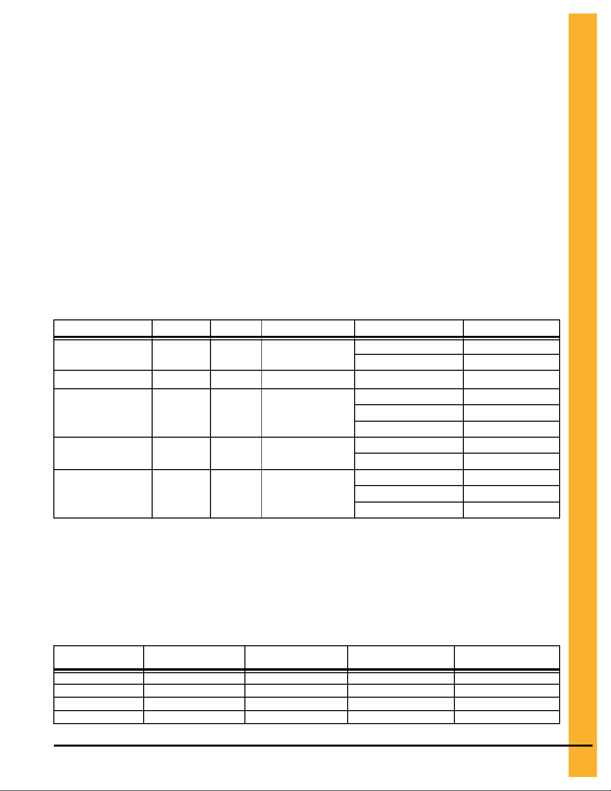
Anchor Bolt Charts
Prior to setting any anchor bolts, you must be sure to have the correct anchor bolt placement. This is very
critical for stiffener alignment during bin erection.
NOTE: Refer to the proper chart to find the anchor chord dimensions that correspond to the bin that is
being built.
Start with one anchor bolt and work from it to the left to locate one quarter of the anchor bolts then to the
right to locate another quarter of the bolts. Working off of the last anchor bolts in each quarter, locate the
remaining anchor bolts in the last two quarters.
Pneg-4090A 90 Ft Diameter 40-Series Bin 15
Page 16
Chapter 2: General Overview
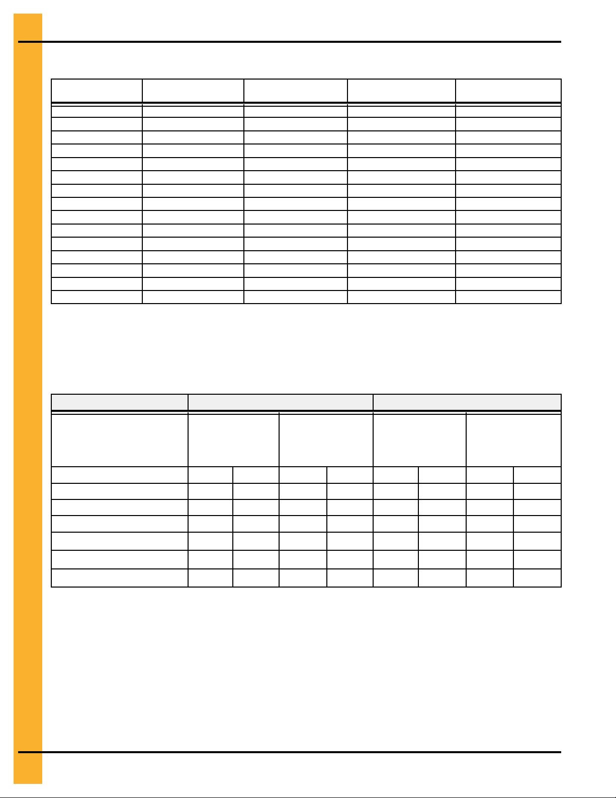
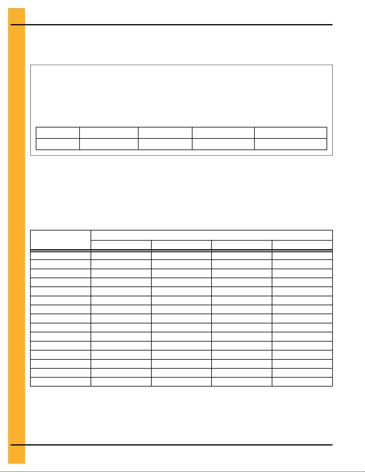
Figure 2-1 Anchor bolt chords for 90 diameter 3–post bin
Bolt Radius (B)
ft and in
45 –
1-15/16 13.765 90
Chord (A)
1 3 – 1-7/8 0.962
2 6 – 3-5/8 1.921
3 9 – 5-5/16 2.878
4 12 – 6-7/8 3.832
5
6 18 – 9-3/8 5.725
7
8 24 – 10-13/16 7.590
9 27 – 10-15/16 8.507
10 30 – 10-3/4 9.417
11 33 – 10-1/16 10.314
ft and in
15 – 8-1/4 4.782
21 – 10-1/4 6.661
Length
m
m and cm
Chord (A)
12 36 – 8-7/8 11.198
13 39 – 7-3/16 12.070
14 42 – 4-7/8 12.925
15 45 – 2 13.767
16 47 – 10-3/8 14.489
17 50 – 6-1/8 15.396
18 53 – 1-1/8 16.183
19
20 58 – 3/4 17.697
21 60 – 5-5/16 18.423
22 62 – 8-15/16 19.125
Anchor Quantity
Length
ft and in
55 –
7-5/16 16.950
m
16 Pneg-4090A 90 Ft Diameter 40-Series Bin
Page 17

Chapter 2: General Overview
Tools Required for Construction
General tools needed to perform this construction
• Combination wrench set 7/16 in. to 1 in.
• Alignment punches 12 in. long
• 1/2 in. Drive socket set and ratchet
• Nail aprons or tool pouches to hold supplies
• Gloves for hand protection
• Tape measure
• 1/2 in. Drive electric or pneumatic torque gun with variable impact capabilities
• 1/2 in. Drive impact socket set
• Lifting jacks
• Center pole roof support
• Step ladders
• Large C-clamp or welding V-grip for clamping
NOTE: Quantities required will depend on the number of workers and size of the bin.
Guidelines for Proper Storage of Grain Bin Materials Prior to Construction
Storage of the build materials prior to construction is important. Do not to allow moisture to remain between
sheets or panels.
Wet storage stain (rust) will develop when closely packed bundles of galvanized material, such as sidewall
and roof sheets, have moisture present. Inspect roof and sidewall bundles on arrival for any moisture. If
moisture is present, it must not be allowed to remain between the sheets. Separate the sheets or panels
immediately and wipe them down. Spray with a light oil or diesel fuel
If possible, sidewall bundles, roof sheets and other closely packed galvanized materials should be stored
in a dry, climate controlled building. If outdoor storage is unavoidable, the materials should be stored so
that they are raised above the ground and vegetation. Any stacking and spacing materials should not be
corrosive or wet. Be sure to protect materials from the weather, but permit air movement around the bundles if possible.
Storing roof bundles and sidewall sheets at a slight incline can also help minimize the presence of moisture. Storing the bundles with the center of the dome up (like an arch) is one option for minimizing moisture
during storage. Sidewall bundles can also be stored on edge but must be secured so that they do not fall
over and cause injury.
If “white rust” or “wet storage stain” occurs, contact the manufacturer immediately about ways to minimize
the adverse effect upon the galvanized coating.
Pneg-4090A 90 Ft Diameter 40-Series Bin 17
Page 18

Chapter 2: General Overview
Overview for a Typical Bin Installation
These are the typical steps one would perform when constructing a grain bin. Procedures may vary
depending different site requirements.
Pre-Assembly Activities
• Sorting and grouping parts
• Assemble A-frames
• Assemble center collar
• Assemble cap plate
Assembly
• Build two rings of sidewall sheets for even ringed bins or one ring or three rings for odd ringed bins,
making sure to caulk all seams.
• Add top outside stiffeners and inside stiffeners at the same time to the two rings of sidewall sheets
(Note: These top stiffeners are the lightest gage stiffeners and will get heavier as the bin is raised.
Therefore, the heaviest stiffeners are located at the bottom of the bin and are installed last.
• Install wind ring to help support the rings
• Install the center collar tower support in the center of the bin
• Install the eave brackets to the inside stiffeners
• Install eave angles to the sidewall sheets (Note how these are aligned.)
• Install the tension member to the eave brackets
• Lift pre-assembled A-frames, installing them in “opposite pairs” (across from one another) to balance
out the load as you install
• Install lower roof panels
• Install upper roof panels
• Cut roof exhauster holes evenly spaced in upper panels
• Install upper flashing
• Install roof exhauster
• Install flat top
18 Pneg-4090A 90 Ft Diameter 40-Series Bin
Page 19

Chapter 2: General Overview
Guidelines for Construction Procedures and Lifting Jack Usage
The following procedure is a guideline when using the required lifting jack. Follow this general guideline
when lifting the bin as sidewalls are being installed.
NOTE: The roof and the top ring for odd ringed bins or the roof and two rings for even ringed bins, will be
installed prior to the beginning of bin lifting procedures. Refer to all other procedures on sidewall
and stiffener installation prior to the start of construction.
IMPORTANT: Begin building with the bin oriented for doors and material handling equipment to be in the
correct position when bin construction is complete.
1. Consider the starting location of the bin, relative to the location of doors and other accessories.
Proper placement of lifting jacks in relationship to anchor bolts could make a difference in final locations. Note that the sidewall sheets will be staggered.
2. The bin is lifted by the use of lifting jacks. Lifting jacks are used to slowly and evenly lift the bin during
construction. Lifting jacks must be properly sized and designed to carry all loads and job site conditions associated with the construction of the bin..
The number of lifting jacks required is best determined by personal experience and expertise. Factors
such as bin size, jack design, construction conditions, support surface, etc., are all to be considered
when deciding how many to use. If in doubt, use one jack on every sheet. The lifting jack must be
adequate to carry all loads. Heavy duty jacks, generally hydraulic or electric powered in the case of
large bins, should be used for commercial installation. All jacks should be secured with braces or otherwise maintained in a stable condition..
Lifting of the bins should not be done under windy conditions
Follow the jack manufacturers recommendations on capacity and operations.
3. Lifting brackets should be attached through the stiffener bolt holes. Normally you will need to attach
to at least four (4) bolts per stiffener.
4. Raise the bin just high enough to assemble the next ring. When lifting the bin, all jacks must lift at
an equal rate. Monitor the lift to ensure even lifting is occurring.
5. To the inside of the first ring, bolt the next ring. Be sure to stagger the sheets and select the proper
gauge material.
6. Lower the bin onto the foundation after assembling and tightening bolts on the new ring or rings.
7. Attach stiffeners to the body sheets every two (2) tiers (on the external surface of the bin). You may
want to leave sheets loose to make the attachment of the stiffeners easier.
8. Now re-bolt the lifting brackets to the lowest ring in place thus far. Continue ring additions by repeating Step 5 and Step 6.
9. Add inside and outside ladders as you continue to raise the bin. (Refer to the manual supplied with
the ladder.)
10.Lower the tank and secure to the foundation before leaving the job site.
11.At the completion of the tank, set stiffeners over the anchor bolts and measure the tank to ensure it is
in a round condition. Consult with GSI for questions on tolerances.
NOTE: For 2 ring doors or vehicle traffic doors, special placement issues may apply. Consult the special
instructions provided with two ring doors or vehicle traffic doors for these options.
Pneg-4090A 90 Ft Diameter 40-Series Bin 19
Page 20

Chapter 2: General Overview
Guidelines for Placement of the Decal Sidewall Sheet
Use the following as a general guideline the proper decal sheet placement.
NOTE: Refer to the stiffener to sidewall attachment detail and specific gauge sheet for the bin. The decal
sheets are located in the third ring from the top. They are to be spaced evenly around the diameter
of the bin.
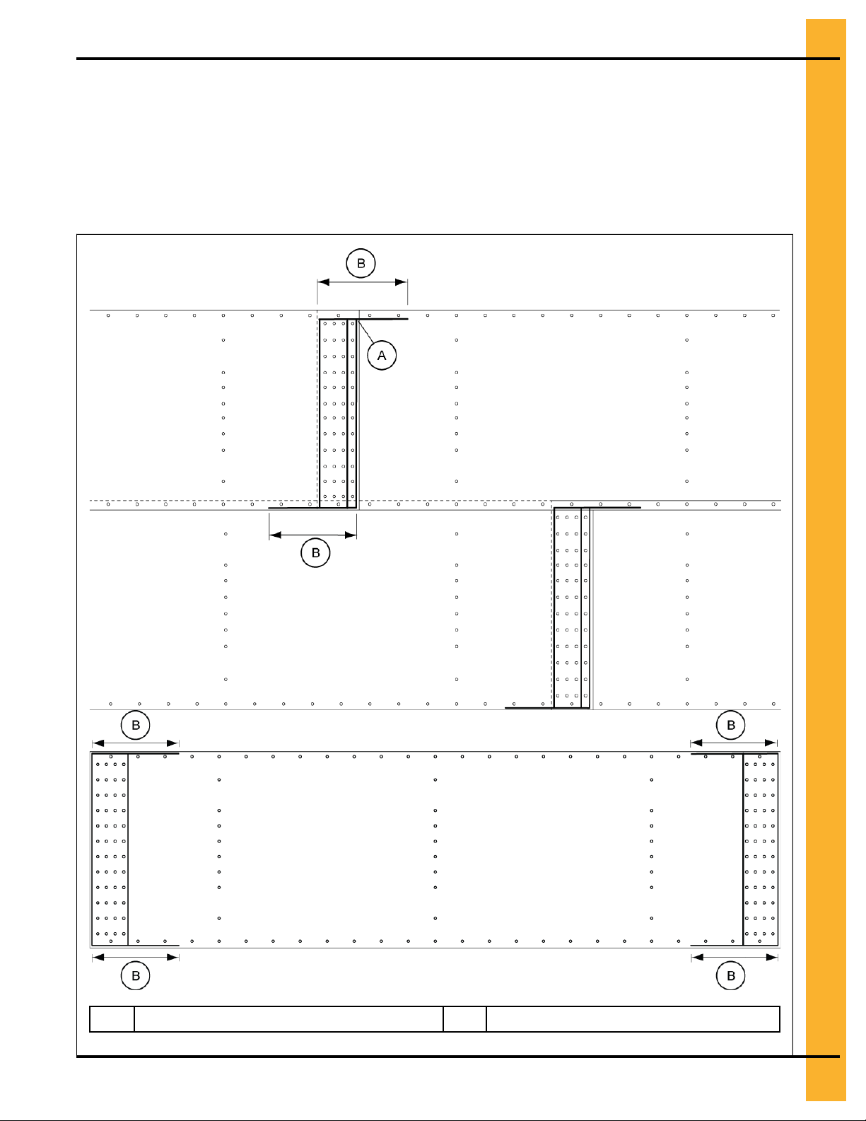
Figure 2-2 3 Post Bin with three rows of stiffeners used on each sidewall sheet
NOTE: Dashed lines represent stiffener locations.
Sample Gauge Sheet
A gauge sheet should be supplied with every bin and contains important information specific to your bin.
The gauge sheet contains the specific details that are unique to your bin. You must reference this sheet to
know the correct order to install the sidewall sheets and stiffeners. The gauge of the sidewall and stiffeners
are marked with colors for identification.
It is important to use the correct hardware for each type of connection. The gauge sheet will identify what
hardware should be used in a vertical seam, horizontal seam, and an overlapping seam for each gauge.
The gauge sheet will also identify the sidewall ring where the wind ring must be installed. This is indicated
by the word ”Standard” under the wind ring column and in the row of the ring it must be installed. If a sidedraw system is used, the word ”Additional” will be located in the row of the ring it must be installed.
Doors are to be installed in the ring or rings denoted with (D).
20 Pneg-4090A 90 Ft Diameter 40-Series Bin
Page 21

Figure 2-3 Sample Gauge Sheet for a 3-Post 90 Diameter Bin
Chapter 2: General Overview
Pneg-4090A 90 Ft Diameter 40-Series Bin 21
Page 22

Chapter 2: General Overview
All information, illustrations, photos, and specifications in this manual are based on the latest
information available at the time of publication. The right is reserved to make changes at any
time without notice.
22 Pneg-4090A 90 Ft Diameter 40-Series Bin
Page 23
3 Hardware Requirements
Topics Covered in this Chapter
▪ Bolt and Nut Pairings
▪ Hardware for 3–Post Sidewall Sheets on bins that are 18 to 90 Ft in Diameter and 105 Ft Bins
that are 27 Rings and Shorter
▪ Bolt Torque Specifications
▪ Identifying Bolt Grades
▪ Color Chart for Bin Hardware Bucket Lids
▪ Bolt Identification
Bolt and Nut Pairings
This chart lists the correct nut to use with each size of bolt.
Nut Part Number
S-396 5/16 YDP Hex
S-3611 5/16 YDP
S-456 3/8 YDP Hex
S-9426 3/8 JS
S-9281 7/16 JS Hex
Nut Size
Type Hex or Flanged
Flanged 5/16 x 1 S-10260
Flanged
Bolt Size
5/16 x 3/4 S-275
5/16 x 1 1/4 S-277
3/8 x 1 S-7487
3/8 x 1 1/2 S-7488
3/8 x 2 S-10165
3/8 x 1 S-7485
3/8 x 1 1/2 S-7488
7/16 x 1 1/2 S-10262
7/16 x 2 S-9389
7/16 x 3 1/4 S-10261
Bolt Part Number
Hardware for 3–Post Sidewall Sheets on bins that are 18 to 90 Ft in Diameter and 105 Ft Bins that are 27 Rings and Shorter
Reference this chart for the hardware requirements for 3–post sidewall sheet connections on bins 18 to 90
ft. in diameter. Reference this chart for the hardware requirements for 3–post sidewall sheet connections
on bins 105 ft. in diameter that are 27 rings and shorter.
Table 3-1 Hardware for 3-Post Sidewall Sheets on 18 to 90 ft. bins and 105 ft Diameter Bins that are 27 Rings and
shorter
Gauge
20
19
18
17
Pneg-4090A 90 Ft Diameter 40-Series Bin 23
Horizontal Seam
Bolt Size (Quantity)
3/8 x 1 (10) 3/8 x 1 (24) 3/8 x 1 (12) 3/8 x 1 (2)
3/8 x 1 (10) 3/8 x 1 (24) 3/8 x 1 (12) 3/8 x 1 (2)
3/8 x 1 (10) 3/8 x 1 (24) 3/8 x 1 (12) 3/8 x 1 (2)
3/8 x 1 (10) 3/8 x 1 (36) 3/8 x 1 (12) 3/8 x 1 (2)
Vertical Seam Bolt
Size (Quantity)
Stiffener to Sidewall
Bolt Size (Quantity)
Overlap Seam Bolt
Size (Quantity)
Page 24
Chapter 3: Hardware Requirements
Table 3-1 Hardware for 3-Post Sidewall Sheets on 18 to 90 ft. bins and 105 ft Diameter Bins that are 27 Rings and
shorter (cont'd.)
Gauge
16
15
14
13
12
11
10
9
8
6
5
11L
10L
9L
8L
Horizontal Seam
Bolt Size (Quantity)
3/8 x 1 (10) 3/8 x 1 (36) 3/8 x 1 (12) 3/8 x 1 (2)
3/8 x 1 (22) 3/8 x 1 (48) 3/8 x 1 (12) 3/8 x 1 (2)
3/8 x 1 (22) 3/8 x 1 (48) 3/8 x 1 (12) 3/8 x 1 (2)
3/8 x 1 (22) 3/8 x 1 (48) 3/8 x 1 (12) 3/8 x 1 (2)
3/8 x 1 (22) 3/8 x 1 (48) 3/8 x 1 (12) 3/8 x 1 (2)
3/8 x 1 (22) 3/8 x 1 (48) 3/8 x 1 (12) 3/8 x 1 (2)
3/8 x 1 (22) 3/8 x 1 (48) 3/8 x 1 (12) 3/8 x 1 (2)
3/8 x 1 (22) 3/8 x 1 (48) 3/8 x 1.5 (12) 3/8 x 1.5 (2)
3/8 x 1 (22) 3/8 x 1 (48) 3/8 x 1.5 (12) 3/8 x 1.5 (2)
3/8 x 1.5 (22) 3/8 x 1.5 (48) 3/8 x 1.5 (12) 3/8 x 1.5 (2)
3/8 x 1.5 (22) 3/8 x 1.5 (48) 3/8 x 1.5 (12) 3/8 x 1.5 (2)
3/8 x 1.5 (22) 3/8 x 1.5 (48) 3/8 x 1.5 (12) 3/8 x 1.5 (2)
3/8 x 1.5 (22) 3/8 x 1.5 (48) 3/8 x 1.5 (12) 3/8 x 1.5 (2)
3/8 x 1.5 (24) 7/16 x 1.5 (48) 3/8 x 1.5 (24) 3/8 x 1.5 (6)
3/8 x 1.5 (24) 7/16 x 1.5 (48) 3/8 x 1.5 (24) 3/8 x 1.5 (6)
Vertical Seam Bolt
Size (Quantity)
Stiffener to Sidewall
Bolt Size (Quantity)
Overlap Seam Bolt
Size (Quantity)
Bolt Torque Specifications
The specification torque table below will help the installer determine how tight a specific bolt must be. A
bolt that has been over tightened can be just as dangerous as one that hasn't been tightened enough.
IMPORTANT: Bolts should not be tightened in excess of the torque specifications chart listed below.
Bolt
Sealing Joints
(joints with seal-
ing washers)
ft-lb N-m ft-lb N-m ft-lb N-m ft-lb N-m
5/16-18 JS Gr 8 with seal 20 27
3/8 -16 JS Gr 8 with seal 30 41
7/16-14 JS Gr 8 with seal 50 68
3/8–16 YDP Gr 8 flanged — —
7/16–14 YDP Gr 8 flanged — —
1/2-13 YDP Gr 8 flanged — —
Minimum Torque Maximum Torque
Structural Joints
(joints without
any sealing
washers)
— —
— —
— —
40 54
65 88
100 135
Sealing Joints
(joints with seal-
ing washers)
25 34
35 47
60 81
— —
— —
— —
Structural Joints
(joints without
any sealing
washers)
— —
— —
— —
45 61
75 101
115 155
24 Pneg-4090A 90 Ft Diameter 40-Series Bin
Page 25
Chapter 3: Hardware Requirements
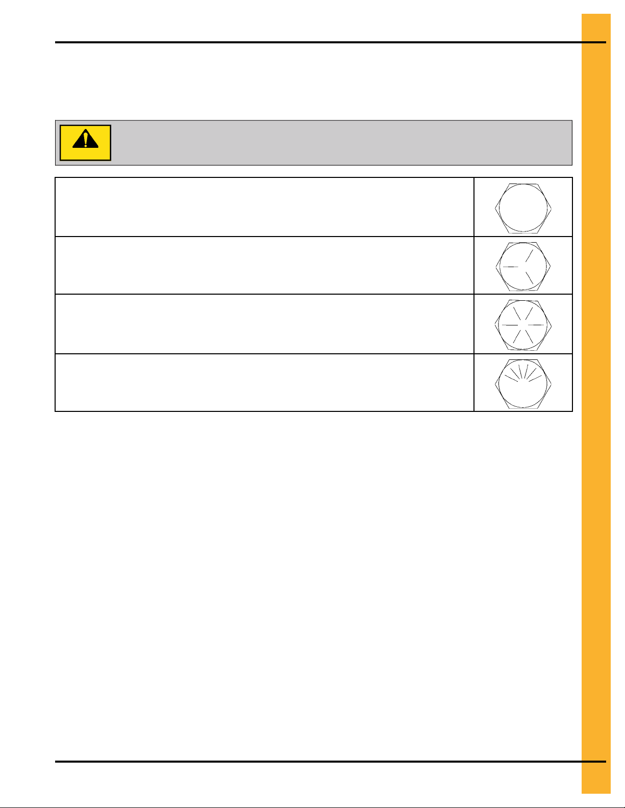
Identifying Bolt Grades
Bolts are identified by grade (or hardness), the grade can be identified by the markings on the head of the
bolt. These markings will be in the form of slash marks and patterns. Use the following as a guide to determine the correct bolt grade.
Under no condition shall any other bolts be substituted for those supplied by GSI.
CAUTION
Grade 2 Bolts
Grade 2 bolts are designated with a plain head and are not used in GSI grain bins.
Grade 5 Bolts
Grade 5 bolts are designated by three slash marks on the head. All 5/16 inch diameter bolts
are to be grade 5 or higher.
Grade 8 Bolts
Grade 8 bolts are designated by six slash marks evenly spaced out around the head of the
bolt. All 3/8, 7/16, and 1/2 inch diameter bolts are to be grade 8 or grade 8.2.
Grade 8.2 Bolts
Grade 8.2 bolts are designated by six slash marks on the head in a sunrise pattern. All 3/8,
7/16, and 1/2 inch diameter bolts are to be grade 8 or grade 8.2.
NOTE: Refer to 2.66" commercial tank bolting requirements for complete bolt usage.
Pneg-4090A 90 Ft Diameter 40-Series Bin 25
Page 26
Chapter 3: Hardware Requirements
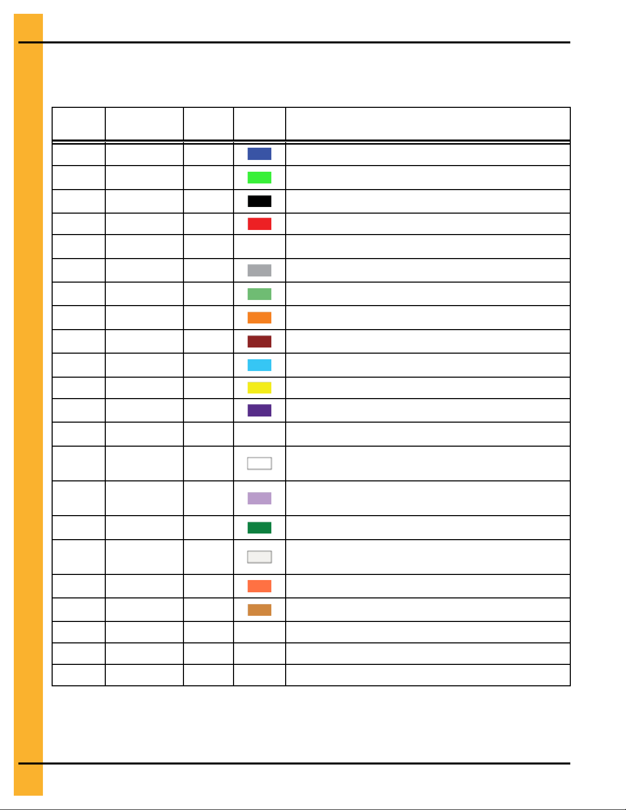
Color Chart for Bin Hardware Bucket Lids
For ease of identification, hardware is separated and identified by buckets with color coded lids. Use the
following chart to help identify the correct hardware.
Part # Color
S-275 Dark Blue
S-10260 Lime Green
S-277 Black
S-396 Red
S-3611 NA
S-7487
S-7485
S-7488
S-7486 Dark Brown
S-10165
S-7489 Yellow
S-9426
Grey
Light Green
Orange
Light Blue
Dark Purple
Bucket
Count
1500
1250
1000
5000
NA In Box
850
1000
650
700
500
4000
2500
Lid Color
Description
5/16 x 3/4 in. YDP bolt pre-assembled with sealing washer
5/16 x 1 in. YDP bolt pre-assembled with sealing washer
5/16 x 1 1/4 in. JS bolt pre-assembled with sealing washer
5/16 in. JS hex nut
5/16 in. YDP flange nut
3/8 x 1 in. JS bolt pre-assembled with sealing washer
3/8 x 1 in. flanged JS bolt without sealing washer
3/8 x 1 1/2 in. JS bolt pre-assembled with sealing washer
3/8 x 1 1/2 in. flanged JS bolt without sealing washer
3/8 x 2 in. JS bolt pre-assembled with sealing washer
3/8 in. JS hex nut
3/8 in. JS flanged nut
S-10250 NA
S-10262 White
S-9389
S-10134 Dark Green
S-10261
S-9281
S-8479
S-10251
S-10252
S-10253
Light Purple
Natural (Clear)
Fire Orange
Light Brown
NA
NA
NA
NA In Box
500
350
300
200
1500
800
NA In Box
NA In Box
NA In Box
7/16 x 1 1/4 in. YDP flanged bolt
7/16 x 1 1/2 in. flanged JS bolt pre-assembled with sealing
washer
7/16 x 2 in. full threaded JS bolt pre-assembled with sealing
washer
7/16 x 2 1/2 in. JS bolt pre-assembled with sealing washer
7/16 x 3 1/4 in. flanged JS bolt pre-assembled with sealing
washer
7/16 in. JS hex nut
7/16 in. YDP special recessed nut
7/16 in. YDP un-serrated flange nut
1/2 x 1 3/4 in. YDP flange bolt
1/2 in. YDP un-serrated flange nut
26 Pneg-4090A 90 Ft Diameter 40-Series Bin
Page 27
Chapter 3: Hardware Requirements
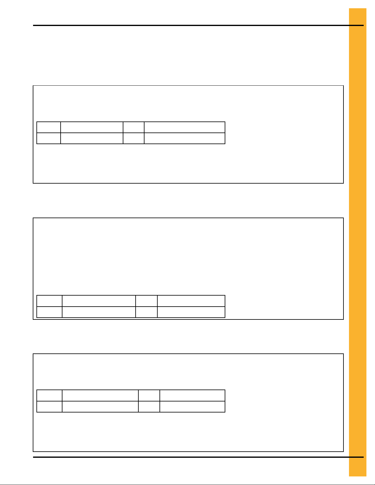
Bolt Identification
Use the following information to identify the bolts and where each must be used during installation.
Bolt S-275
An S–275 is a 5/16 x 3/4 in. YDP bolt that is pre-assembled with a sealing washer.
Bolt (S-275) is used in the following locations:
• Use in accessories.
• Color of bucket lid is dark blue.
0.945 in. (2.40 cm)
A
0.750 in. (1.90 cm)
B
C Grade 5
D Grade 5
Bolt S-10260
An S–10260 is a 5/16 x 1 in. JS bolt that is pre-assembled with a sealing washer.
Bolt (S-10260) is used in the following locations:
• Use to connect roof panels together where they overlap.
• Use when connecting eave angle to sidewall sheet.
• The color of the bucket lid is lime green.
• Use to connect eave clip to sidewall sheet on bins that are 48 ft
diameter and smaller.
• Use to attach roof panels to flashing on bins that are 48 ft diameter and smaller.
A
B
1.300 in. (3.30 cm )
1.000 in. (2.54 cm)
C Grade 8
D Grade 8.2
Bolt S-277
An S–277 is a 5/16 x 1 1/4 in. YDP bolt pre-assembled with a sealing washer.
Bolt (S-277) is used in the following locations:
• Use in accessories.
• The color of the bucket lid is black.
A
B
Pneg-4090A 90 Ft Diameter 40-Series Bin 27
1.445 in. (3.67 cm )
1.250 in. (3.17 cm)
C Grade 5
D Grade 5
Page 28
Chapter 3: Hardware Requirements
Bolt S-7485
An S–7485 is a 3/8 x 1 in. JS hex bolt with flanged head and without a sealing washer.
Bolt (S-7485) is used in the following locations:
• Use to splice the stiffeners together on the flanges. (A flange nut
is used on the nut side of the connection.)
• Use to splice the laminated stiffeners together. (A flange nut is
used on the nut side of the connection.)
• The color of bucket lid is light green.
1.350 in. (3.43 cm)
A
1.000 in. (2.54 cm)
B
C Grade 8
D Grade 8.2
Bolt S-7487
An S–7487 is a 3/8 x 1 in. JS bolt that is pre-assembled with a sealing washer.
Bolt (S-7487) is used in the following locations:
• Use in all sidewall connections for 20 gauge through 10 gauge
sidewall to sidewall sheets.
• Use for horizontal and vertical seam connections for 9 gauge
through 8 gauge sidewall sheets.
• Use when attaching base angle to sidewall sheet on flat bottom
bins.
• Color of bucket lid is grey.
NOTE: Do not use to splice the stiffeners together on the flanges
where they connect to each other or the splice plates.
1.350 in. (3.43 cm)
A
1.000 in. (2.54 cm)
B
C Grade 8
D Grade 8.2
Bolt S-7486
An S–7486 is a 3/8 x 1 1/2 in. JS hex bolt with a flanged head without a sealing washer.
Bolt (S-7486) is used in the following locations:
• Use in special seismic tanks.
• The color of the bucket lid is dark brown.
1.850 in. (4.70 cm)
A
1.500 in. (3.81 cm)
B
28 Pneg-4090A 90 Ft Diameter 40-Series Bin
C Grade 8
D Grade 8.2
Page 29
Chapter 3: Hardware Requirements
Bolt S-7488
An S–7488 is a 3/8 x 1 1/2 in. JS bolt that is pre-assembled with a sealing washer.
Bolt (S-7488) is used in the following locations:
• Use in all stiffener to sidewall and overlap connections where the
sidewall is 9 gauge or thicker.
• Use in vertical and horizontal seams on sidewall that is 6 gauge
or thicker.
• The color of the bucket lid is orange.
NOTE: Do not use in flanges where the splice plate bolts to the stiff-
eners. Sealing washers should not be used for these
connections.
A
1.850 in. (4.70 cm) C Grade 8
B
1.500 in. (3.81 cm)
D
Grade 8.2
Bolt S-10252
An S–10252 is a 1/2 x 1 3/4 in. YDP flange bolt.
Bolt (S-10252) is used in the following locations:
• Use in bins 72 to 135 ft in diameter.
• Use in tension plate to eave bracket connection.
• Use in rafter clip to rafter connection.
• Use in laminated purlins.
• Use in purlin clip to rafter and purlin clip to purlin connections.
• Use in X-brace to rafter connection.
• Use in center collar splice connection.
• Use in center collar channel clip to center collar.
• Use in rafter to center collar and rafter to eave bracket
connections.
• Use in center collar channel to clip.
• Delivered in a box, not a bucket.
1.833 in. (4.66 cm)
A
C Grade 8
1.495 in. (3.80 cm)
B
Pneg-4090A 90 Ft Diameter 40-Series Bin 29
D Grade 8.2
Page 30
Chapter 3: Hardware Requirements
Bolt S-10261
An S–10261 is a 7/16 x 3 1/4 in. JS bolt that is pre-assembled with a sealing washer.
Bolt (S-10261) is used in the following locations:
• Use in wind ring splice and over pipe connections.
• Lid color of bucket is natural (clear).
3.645 in. (9.26 cm)
A
3.250 in. (8.26 cm)
B
C Grade 8
D Grade 8.2
30 Pneg-4090A 90 Ft Diameter 40-Series Bin
Page 31

4 Assembling Sidewall Sheets
Topics Covered in this Chapter
▪ Color Codes for Sidewall Gauge Identification
▪ Orientation Detail for Top Sidewall Sheets
▪ Caulking Detail for Standard (Non-Laminated) Sheets
▪ Caulking Detail for Laminated Quad Pattern Sheets
Color Codes for Sidewall Gauge Identification
Use this chart to interpret the color code painted on the corners of the sidewall sheets.
Table 4-1 Color codes for sidewall gauges
Sidewall Gauge Color Code
20
19 Black and Yellow
18 Orange
17
16
15
14 Green
13
12
11 Pink
10
9 Dark Blue and Orange
8
6 White
5
Table 4-2 Stripe Colors for Special Sidewall Characteristics
Red
Light Blue and Pink
Blue
Red and Brown
Dark Blue and Yellow
Black
Light Blue
Yellow
Fluorescent Green
Extra Stripe Colors
Type of Sidewall Stripe Color
BFT Blue
Laminated
Hex Pattern
Special Galvanized 115 Fluorescent Red and Orange
Special Galvanized 140
Pneg-4090A 90 Ft Diameter 40-Series Bin 31
Gold
Ochre
Florescent Pink
Page 32

Chapter 4: Assembling Sidewall Sheets
Table 4-2 Stripe Colors for Special Sidewall Characteristics (cont'd.)
Extra Stripe Colors
Type of Sidewall Stripe Color
Special Galvanized 160
NOTE: Stripe colors are located in the middle of each side of the bundle.
Florescent Red and Fluorescent Pink
Orientation Detail for Top Sidewall Sheets
To avoid the misalignment of the holes, it is necessary to use the correct orientation of the sidewall sheet
during installation.
NOTE: Always assemble the top sidewall sheets with the orientation shown.
Figure 4-1 3–Post top sidewall sheet orientation
A Top of the top sidewall sheet B Bottom of the top sidewall sheet
Caulking Detail for Standard (Non-Laminated) Sheets
To keep out moisture from overlapping the sheets, it is necessary to apply caulk to each sheet prior to
installing.
NOTE: Always assemble the sidewall sheets with the overlap in the same direction.
• Apply a strip of caulk near the outside edge of the outer sheet and between the outer two rows of
bolts (A), then apply a strip of caulk 10 in. (25.4 cm) long along the horizontal seams (B), as shown in
the figure below.
32 Pneg-4090A 90 Ft Diameter 40-Series Bin
Page 33

Chapter 4: Assembling Sidewall Sheets
Figure 4-2 Standard and quad punched sidewall sheets as viewed from the outside
A
Vertical strip of caulk
B
10 in. (25.4 cm) Horizontal strip of caulk
• Before bolting the next ring into place, apply one 10 in. strip of caulk (C) on the front of the underlapped sheet at each joint.
• Also, place a 10 in. (25.4 cm) strip of caulk (D) along the lower horizontal edge of the lapping sheet at
every vertical seam. This will fill the space that occurs between the holes caused by the overlapping
sheets.
Pneg-4090A 90 Ft Diameter 40-Series Bin 33
Page 34

Chapter 4: Assembling Sidewall Sheets
Figure 4-3 Caulking detail as viewed from inside of the bin
C 10 in. (25.4 cm) Strip of caulk
D
10 in. (25.4 cm) Strip of caulk
• Use the supplied tube caulk to fill the larger gaps that occur with heavier gauges and laminated
gauges. See Caulking Detail for Laminated Quad Pattern Sheets, page 35 for details about caulk
laminated sidewall sheets.
34 Pneg-4090A 90 Ft Diameter 40-Series Bin
Page 35
Chapter 4: Assembling Sidewall Sheets
Caulking Detail for Laminated Quad Pattern Sheets
To keep out moisture from overlapping the sheets, it is necessary to apply caulk to each sheet prior to
installing.
Caulking and Assembling the Individual Sidewall Sheets
Each sidewall sheet must be layered and caulked prior to assembling sidewall sheet seams together.
Figure 4-4 Laminated quad punched sidewall panel view from outside of the bin
A Strip of caulking B 12 in. (30.4 cm) horizontal strip of caulking
Pneg-4090A 90 Ft Diameter 40-Series Bin 35
Page 36

Chapter 4: Assembling Sidewall Sheets
• When assembling two assembled laminated sheets to each other, apply a strip of caulk (A) near the
outside edge of the outer sheet, between the outer two (2) rows of bolts and outside the last row of
bolts.
• Place a strip of caulk (B) 12 in. (30.4 cm) long to each the horizontal seams.
NOTE: Before bolting the next ring into place, apply a strip of caulk 12 in. (30.4 cm) long on the front
of the under lapped sheet at each joint.
• Also, a 12 in. (30.4 cm) strip of caulk is to be placed along the lower horizontal edge of the lapping
sheet at the vertical seam. This will fill the space that occurs between the holes caused by the overlapping sheets.
When assembling two sheets to make a laminated sheet assembly (C), apply a row of caulk all around the
vertical seam.
Use the supplied tube caulk to fill the larger gaps that occur with heavier gauges and laminated sheets.
Figure 4-5 Caulking detail for assembled laminated sidewall sheets
B
12 in. (30.4 cm) horizontal strip of caulk C Laminated sheet detail (caulk not shown)
36 Pneg-4090A 90 Ft Diameter 40-Series Bin
Page 37

5 Base Angle Installation
Topics Covered in this Chapter
▪ Installing the Base Angle
▪ Anchor Bolt Detail
▪ Installing the Base Angle Shims
▪ Anchor Bolt Washer Installation
Installing the Base Angle
Installing the base angle ring will help reinforce and seal the final ring.
What You Should Know
The base angle overlap should be offset two holes from the stiffener. Do not place overlap in line with the
stiffener.
1. Place a section of the base angle (B) to the bottom portion of the final ring (A).
NOTE: The sidewall sheet will sit on top of the base angle with the vertical portion of the base angle
on the inside of the bin. and each end of the base angle will connect to the next base angle
section.
2. Install bolts (C) and nuts (D) as shown, but leaving the end holes of each section unfilled until the
next section is to be installed.
3. Attach the next base angle section overlapping the end holes (F) and install bolts (C) and nuts (D).
4. Repeat this procedure for the remaining base angle sections (B) over lapping the previously installed
base angle section.
5. Before the bolts (C) are tightened, push the base angle tight against the bottom edge of each sheet.
6. Tighten the hardware to the recommended torque specifications, see Bolt Torque Specifications,
page 24.
7. Before lowering the bin, apply the optional mastic sealer strip (G) to the entire underneath side of the
base angle.
NOTE: If optional mastic sealer strip is not used, it is recommended that some other method should
be utilized to seal the base ring to the concrete.
8. Lower the bin onto the foundation and check for an adequate seal.
Pneg-4090A 90 Ft Diameter 40-Series Bin 37
Page 38

Chapter 5: Base Angle Installation
Figure 5-1 Exploded view of base angle (view from inside the bin)
A Final ring assembly D
B
Base angle (B-6753)
C 3/8 x 1 in. bolt (S-7487)
3/8 in. nut (S-9426)
E
Base angle offset example
F
Optional mastic sealer (or equivalent)
38 Pneg-4090A 90 Ft Diameter 40-Series Bin
Page 39

Chapter 5: Base Angle Installation
Anchor Bolt Detail
The following is the minimum requirement for anchorage on standard tanks. Refer to sidedraw instructions
for special anchorage details.
• 3/4 in. diameter anchor bolt (A) is the minimum allowed.
• Exposed anchor bolt thread height (B), 3 in. (7.62 cm)
• Overall anchor bolt length (C), 18 in. (45.72 cm)
• Hook Length (D), 4-3/4 in. (12.065 cm)
Figure 5-2 Anchor bolt example (3/4 in. diameter anchor bolt shown)
Pneg-4090A 90 Ft Diameter 40-Series Bin 39
Page 40
Chapter 5: Base Angle Installation
Installing the Base Angle Shims
A section of the base boot plate will rest on top of the base angle, therefore causing the base boot to rest
unevenly on the foundation. To offset this, base angle shims are required to ensure the base boot sets
evenly on the foundation.
What You Should Know
1. Place the required base angle shim around the anchor bolt next to the base angle.
2. Place the base stiffener over the anchor bolt onto the required shim.
3. If needed, add standard shims under the required base angle shim.
NOTE: If more than one additional shim is required, then the shims must be welded together to the
base plate or the base plate must be grouted to provide the proper elevation.
Figure 5-3 Base Angle Shims
6 x 9 Base plate (CTS-2121XX or CTS-
A
2110XX)
B-7027 (Required base angle shim for 6 x
B
9 base plate)
SS-6953 (Standard shim for 6 x 9 base
C
plate)
8 x 10 Base plate (CTS-2109XX or CTS-
D
2131XX)
40 Pneg-4090A 90 Ft Diameter 40-Series Bin
B-7028 (Required base angle shim for 8 x 10 base
E
plate)
SS-7212 (Standard shim for 8 x 10 base plate)
F
Base angle (B-7025XX or B-7026XX)
G
Page 41
Chapter 5: Base Angle Installation
Anchor Bolt Washer Installation
Anchor bolt washers help to cover the oversized hole in the base plate.
Before You Begin
Anchor bolts are secured, and base plates installed.
1. Place a square plate washer (B) onto the anchor bolt (A).
NOTE: A square plate washer (provided) must be installed between the base boot (C) and washer
(D).
2. Install a washer (D), and secure with a nut (E).
3. Tighten to the recommended torque specification, see Bolt Torque Specifications, page 24.
Figure 5-4 Base stiffener assembly
3/4 in. bolt assembly package (B-4161)
A
Square anchor plate washer (3/4 in. HT-635) ,
B
(1 in. B-6756)
C Base boot
3/4 in. washer (S-866)
D
3/4 in. nut (S-234)
E
Pneg-4090A 90 Ft Diameter 40-Series Bin 41
Page 42

NOTES
42 Pneg-4090A 90 Ft Diameter 40-Series Bin
Page 43

6 Stiffeners
Topics Covered in this Chapter
▪ Stiffener Part Number Description
▪ Color Codes for Stiffener Gauge Identification
▪ Outside Stiffened Laminated Stiffener to Sidewall (10 Gauge Laminated and Thicker Only)
▪ Standard Stiffeners
▪ Top Stiffeners
▪ Stiffeners Splice
▪ Base Stiffeners
▪ Base Boots
▪ Close-Punch Connection for a One-Ring Top Stiffener (16 Ga) and a Two-Ring Stiffener (16
Ga)
▪ Two-Ring Top Stiffener to a Two-Ring Stiffener (15–16 Ga) Connection
▪ Close-Punch Connection for a Two-Ring Top Stiffener to a Two-Ring Stiffener (16 Ga)
▪ Two-Ring Stiffener (15-16 Ga) to a Two-Ring Stiffener (15–16 Ga) Connection
▪ Close-Punch Connection for a Two-Ring Stiffener (16 Ga) to a Two-Ring Stiffener (16 Ga)
▪ Two-Ring Stiffener (0–14 Ga) to a Two-Ring Stiffener (0–14 Ga) Connection
▪ Close-Punch Connection for a Two-Ring Stiffener (0–14 Ga) to a Two-Ring Stiffener (0–14
Ga)
▪ Two-Ring Stiffener (0–14 Ga) to a Close-Punch Base Stiffener (2–8 Ga) Connection
▪ Close-Punch Connection for a Two-Ring Stiffener (0–14 Ga) to a Base Stiffener (2–8 Ga)
▪ Two-Ring Stiffener (0–14 Ga) to a Base Stiffener (10–16 Ga) Connection
▪ Two-Ring Stiffener (2–14 Ga) to a Base Stiffener (10–16 Ga) Connection
▪ Two-Ring Stiffener (15–16 Ga) to a Base Stiffener (10–16 Ga) Connection
▪ Close-Punch Connection for a Two-Ring Stiffener (16 Ga) to a Base Stiffener (10–16 Ga)
▪ Close-Punch Two-Ring Stiffener (2–14 Ga) to a Laminated Stiffener (2 Ga) with an Insert (10–
14 Ga)
▪ Close-Punch Laminated Stiffeners (2 Ga) with Inserts (10–14 Ga)
▪ Close-Punch Laminated Stiffener (2 Ga) with an Insert (10–14 Ga) to a Laminated Base Stiff-
ener (2–5 Ga) with a Base Insert (2–14 Ga)
▪ Base Stiffener (10–16 Ga) to a Base Boot Connection
▪ Close-Punch Connection for a Base Stiffener (10–16 Ga) to a Base Boot
▪ Close-Punch Connection for a Base Stiffener (2+2 Ga – 8 Ga) to a Base Boot
▪ Close-Punch Laminated Base Stiffener (2 Ga) with Insert (2+14 to 2+10 Ga) to a Base Boot
▪ Close-Punch Standard Stiffener to a 12–Bolt Pattern Laminated Stiffener with Insert
▪ 12–Bolt Pattern Close-Punch Laminated Stiffeners with Insert
▪ Close-Punch 12–Bolt Pattern Laminated Stiffener to Laminated Base Stiffener with an Inserts
to a Base Boot
▪ Close-Punch 12–Bolt Pattern Laminated Stiffener to Laminated Base Stiffener with an Inserts
to a Base Boot
Pneg-4090A 90 Ft Diameter 40-Series Bin 43
Page 44

Chapter 6: Stiffeners
Stiffener Part Number Description
Part numbers are printed on the end of each stiffener with the last two numbers designating the gauge of
the material.
Example: CTS-206314 will be printed on a 14 gauge, standard two-ring stiffener. If the stiffener was 8
gauge, it would change the part number to CTS-206308.
The part numbers in the following tables use an “XX” at the end of the number to represent the gauge of
the material.
Color Codes for Stiffener Gauge Identification
Use these charts to interpret the color code painted on the ends of the stiffeners.
Table 6-1 Color codes for stiffener gauges
Sidewall Gauge Color Code
0 No Color (Zinc)
2 Ochre
5
6 White
8
9 Dark Blue and Orange
10
11
12
13
14 Dark Green
15
16
17
18 Orange
Fluorescent Green
Yellow
Light Blue
Pink
Black
Dark Blue and Yellow
Red and Brown
Dark Blue
Light Blue and Pink
Table 6-2 Stripe color codes for stiffener gauges
Stiffener Type Stripe Color
Base Stiffener
Back (Laminated) Dark Green
Insert (Laminated) Gold
Close Punched
Special Galvanized 115 Fluorescent Red and
Special Galvanized 140 Florescent Pink
Special Galvanized 165
12–Bolt Pattern
Stiffener
NOTE: Extra colored stripes will be centered on
the gauge color. If more than one color of stripe is
needed, they will be painted next to each other and
centered on the gauge color.
Florescent Pink and
Fluorescent Orange
Light Blue
Orange
Brown
Red
44 Pneg-4090A 90 Ft Diameter 40-Series Bin
Page 45

Chapter 6: Stiffeners
Outside Stiffened Laminated Stiffener to Sidewall (10 Gauge Laminated and Thicker Only)
Use the following information to attach the outside stiffened laminated stiffener to the sidewall.
Place a sealing washer (D) between the stiffener and the sidewall sheet on the first stiffener to sidewall
bolt down from the horizontal seam (laminated, 10 gauge and thicker only). Placing a small amount of tube
caulk on the washer placing on the sidewall is an aid to installation.
Figure 6-1 Outside stiffened laminated stiffener to sidewall detail (10 Gauge Laminated and Thicker Only)
A Laminated stiffeners C
B
3/8 in. flange nut (S-9426)
Pneg-4090A 90 Ft Diameter 40-Series Bin 45
3/8 x 1-1/2 in. flange bolt (S-7488) or
3/8 x 2 in. flange bolt (S-10165)
D
Sealing washer (S-9467)
Page 46

Chapter 6: Stiffeners
Standard Stiffeners
Use the following information to determine the differences between the types of standard two-ring
stiffeners.
Figure 6-2 Standard stiffeners
Call
Out
A CTS-2063XX Two-ring stiffener 63.938 in. (162 cm) 10 – 14
B CTS-2064XX Two-ring stiffener 63.938 in. (162 cm) 15 – 16
C CTS-2073XX Two-ring stiffener (close-punch) 63.938 in. (162 cm) 2–10,12,14
D CTS-2075XX Two-ring stiffener (close-punch) 63.938 in. (162 cm) 16
E CTS-2079XX Two-ring laminated stiffener
F CTS-2081XX Two-ring insert (close-punch) 63.938 in. (162 cm) 10–14
G CTS-2137XX Two-ring laminate stiffener (close-
H CTS-2138XX Two-ring insert (close-punch) 63.938 in. (162 cm) 2–14
Part Number Description Length Available
Gauges
63.938 in. (162 cm) 2 – 5
(close-punch)
63.938 in. (162 cm) 2
punch)
46 Pneg-4090A 90 Ft Diameter 40-Series Bin
Page 47

Chapter 6: Stiffeners
Top Stiffeners
Use the following information to determine the differences between the three types of top stiffeners.
Figure 6-3 Images of the top stiffeners
Call
Out
A CTS-2069XX Inside stiffener (for roof) 23.938 in. (56 cm) 2 – 8, 10, 12, 14
B CTS-2118XX One-ring top stiffener (close
C CTS-2111XX Two-ring top stiffener 53.938 in. (137 cm) 15 – 16
D
Part Number Description Length Available
Gauges
21.938 in. (56 cm) 16
punch)
CTS-2116XX Two-ring top stiffener
(close-punch)
53.938 in. (137 cm) 16
Pneg-4090A 90 Ft Diameter 40-Series Bin 47
Page 48
Chapter 6: Stiffeners
Stiffeners Splice
Use the following information to determine the gauge of the splice needed to connect the stiffeners.
Figure 6-4 Stiffener splice
Call Out Part Number Description Length Available Gauges
A CTS–2091XX Stiffener splice 10 in. (25.4 cm) 8, 10, 12, 14
Use the following chart to determine the gauge of the splice, which is determined by the gauge of the stiffeners that are being connected. If connecting a heavier gauge to a lighter gauge stiffener, always use the
heavier gauge splice for the 13 to 12, 8 to 6, and 2 to 0 gauge connections.
For example: If connecting a 13 gauge stiffener to a 12 gauge stiffener, use the 12 gauge splice. If connecting an 8 gauge stiffener to a 6 gauge stiffener, use the 10 gauge splice. If connecting a 2 gauge stiffener to a 0 gauge stiffener, use the 8 gauge splice.
Table 6-3 Splice Usage
Stiffener Gauge
8 Gauge 10 Gauge 12 Gauge 14 Gauge
18 X
17 X
16 X
15 X
14 X
13 X
12 X
11 X
10 X
9 X
8 X
6 X
5
2 X
0 X
Splice Gauge
X
48 Pneg-4090A 90 Ft Diameter 40-Series Bin
Page 49

Chapter 6: Stiffeners
Base Stiffeners
Use the following information to determine the differences between the base stiffeners.
Figure 6-5 Images of the base stiffeners
Call Out
A
B
C CTS-2115XX Base stiffener 72.094 in. (183 cm) 10, 12, 14, 16
D
E
F
G CTS-2134XX
H
I
Pneg-4090A 90 Ft Diameter 40-Series Bin 49
Part Number Description Length
CTS–2119XX Base stiffener 72.094 in. (183 cm) 2 – 8
CTS-2123XX Base stiffener 72.430 in. (184 cm) 9, 10, 12, 14, 16
CTS-2114XX Laminated base stiffener 72.061 in. (183 cm) 2 – 5
CTS-2113XX
CTS-2133XX Laminated base stiffener 72.088 in. (183 cm) 2
CTS-2135XX Laminated base stiffener 71.775 in. (182 cm) 2
CTS-2136XX
Base insert
Base insert
Base insert
66.438 in. (169 cm) 2 – 8, 10, 12, 14
71.775 in. (182 cm) 10,12,14
71.775 in. (182 cm) 2 – 8
Available Gauges
Page 50

Chapter 6: Stiffeners
Base Boots
Use the following information to determine the differences between the base boots.
Figure 6-6 Images of the base boots
Call Out Part Number Description Height Base Plate Size
A CTS–2121XX Base boot weldment for 16
through 9 Ga. base stiffeners
B CTS-2110XX Base boot weldment for 8 through
a laminated 2 Ga. with an 11 Ga.
insert
C CTS-2109XX Base boot for 2 Ga. laminated
base stiffeners with inserts from
10 through 2 gauges.
D CTS-2131XX Base boot weldment for 2+8 to 2
+2 base stiffeners.
11.391 in.
(29 cm)
11.391 in.
(29 cm)
11.391 in.
(29 cm)
11.391 in.
(29 cm)
6 x 9 x 3/8 in.
(15 x 23 x 0.95
cm)
6 x 9 x 3/4 in.
(15 x 23 x 1.90
cm)
8 x 10 x 3/4 in.
(20 x 25 x 1.90
cm)
8 x 10 x 1–1/2 in.
(20 x 25 x 3.81
cm)
50 Pneg-4090A 90 Ft Diameter 40-Series Bin
Page 51

Chapter 6: Stiffeners
Close-Punch Connection for a One-Ring Top Stiffener (16 Ga) and a Two-Ring Stiffener (16 Ga)
Reference the following information for a close-punch connection of a one-ring top stiffener (CTS-2118XX)
to a two-ring stiffener (CTS-2075XX).
Figure 6-7 One-Ring Top Stiffener (16 Ga) and a Two-Ring Stiffener (16 Ga) Close-Punch Connection
A One-ring top stiffener (CTS-2118XX)
B Two-ring stiffener (CTS-2075XX)
C Splice (CTS-2091XX)
D 3/8 x 1 Bolt (S-7485)
E
3/8 Nut (S-9426)
F
Completed assembly
NOTE: Two-post stiffeners shown. The bolt pattern will
vary for three-post. Only place bolts where
holes in the stiffeners align with holes in the
sidewall sheet.
Two-Ring Top Stiffener to a Two-Ring Stiffener (15–16 Ga) Connection
Reference the following information when connecting a two-ring top stiffener (CTS-2111XX) to a two-ring
stiffener (CTS-2064XX).
Figure 6-8 Two-Ring Top Stiffener to a Two-Ring Stiffener (15–16 Ga) Connection
A
Two-ring top stiffener (CTS-2111XX)
B
Two-ring stiffener (CTS-2064XX)
C Splice (CTS-2091XX)
D
NOTE: Two-post stiffeners shown. The bolt pattern will
3/8 x 1 Bolt (S-7485)
E 3/8 Nut (S-9426)
F Completed assembly
vary for three-post. Only place bolts where
holes in the stiffeners align with holes in the
sidewall sheet.
Pneg-4090A 90 Ft Diameter 40-Series Bin 51
Page 52
Chapter 6: Stiffeners
Close-Punch Connection for a Two-Ring Top Stiffener to a Two-Ring Stiffener (16 Ga)
Reference the following information for a close-punch connection of a two-ring top stiffener (CTS-2116XX)
to a two-ring stiffener (CTS-2075XX).
Figure 6-9 Two-Ring Top Stiffener to a Two-Ring Stiffener (16 Ga) Close-Punch Connection
A Two-ring top stiffener (CTS-2116XX)
B Two-ring stiffener (CTS-2075XX)
C Splice (CTS-2091XX)
D 3/8 x 1 Bolt (S-7485)
E
F
NOTE: Two-post stiffeners shown. The bolt pattern will
3/8 Nut (S-9426)
Completed assembly
vary for three-post. Only place bolts where
holes in the stiffeners align with holes in the
sidewall sheet.
Two-Ring Stiffener (15-16 Ga) to a Two-Ring Stiffener (15–16 Ga) Connection
Reference the following information when connecting a two-ring stiffener (CTS-2064XX) to a two-ring stiffener (CTS-2064XX).
Figure 6-10 Two-Ring Stiffener (15-16 Ga) to a Two-Ring Stiffener (15–16 Ga) Connection
A
B
C Splice (CTS-2091XX)
D
E 3/8 Nut (S-9426)
F Completed assembly
NOTE: Two-post stiffeners shown. The bolt pattern will
52 Pneg-4090A 90 Ft Diameter 40-Series Bin
Two-ring stiffener (CTS-2064XX)
Two-ring stiffener (CTS-2064XX)
3/8 x 1 Bolt (S-7485)
vary for three-post. Only place bolts where
holes in the stiffeners align with holes in the
sidewall sheet.
Page 53

Chapter 6: Stiffeners
Close-Punch Connection for a Two-Ring Stiffener (16 Ga) to a Two-Ring Stiffener (16 Ga)
Reference the following information for a close-punch connection of a two-ring stiffener (CTS-2075XX) to a
two-ring stiffener (CTS-2075XX).
Figure 6-11 Two-Ring Stiffener (16 Ga) to a Two-Ring Stiffener (16 Ga) Close-Punch Connection
A Two-ring stiffener (CTS-2075XX)
B Two-ring stiffener (CTS-2075XX)
C Splice (CTS-2091XX)
D 3/8 x 1 Bolt (S-7485)
E
F
NOTE: Two-post stiffeners shown. The bolt pattern will
3/8 Nut (S-9426)
Completed assembly
vary for three-post. Only place bolts where
holes in the stiffeners align with holes in the
sidewall sheet.
Two-Ring Stiffener (0–14 Ga) to a Two-Ring Stiffener (0–14 Ga) Connection
Reference the following information when connecting a two-ring stiffener (CTS-2063XX) to a two-ring stiffener (CTS-2063XX).
Figure 6-12 Two-Ring Stiffener (0–14 Ga) to a Two-Ring Stiffener (0–14 Ga) Connection
A
B
C Splice (CTS-2091XX)
D
E
F
NOTE: Two-post stiffeners shown. The bolt pattern will
Pneg-4090A 90 Ft Diameter 40-Series Bin 53
Two-ring stiffener (CTS-2063XX)
Two-ring stiffener (CTS-2063XX)
3/8 x 1 Bolt (S-7485)
3/8 Nut (S-9426)
Completed assembly
vary for three-post. Only place bolts where
holes in the stiffeners align with holes in the
sidewall sheet.
Page 54

Chapter 6: Stiffeners
Close-Punch Connection for a Two-Ring Stiffener (0–14 Ga) to a Two-Ring Stiffener (0–14 Ga)
Reference the following information for a close-punch connection of a two-ring stiffener (CTS-2073XX) to a
two-ring stiffener (CTS-2073XX).
Figure 6-13 Two-Ring Stiffener (0–14 Ga) to a Two-Ring Stiffener (0–14 Ga) Close-Punch Connection
A Two-ring stiffener (CTS-2073XX)
B Two-ring stiffener (CTS-2073XX)
C Splice (CTS-2091XX)
D 3/8 x 1 Bolt (S-7485)
E
F
NOTE: Two-post stiffeners shown. The bolt pattern will
3/8 Nut (S-9426)
Completed assembly
vary for three-post. Only place bolts where
holes in the stiffeners align with holes in the
sidewall sheet.
Two-Ring Stiffener (0–14 Ga) to a Close-Punch Base Stiffener (2–8 Ga) Connection
Reference the following information when connecting a two-ring stiffener (CTS-2063XX) to a close-punch
two-ring stiffener (CTS-2119XX).
Figure 6-14 Two-Ring Stiffener (0–14 Ga) to a Close-Punch Two-Ring Stiffener (2–8 Ga) Connection
A
B
C Splice (CTS-2091XX)
D
E
F
NOTE: Two-post stiffeners shown. The bolt pattern will
54 Pneg-4090A 90 Ft Diameter 40-Series Bin
Two-ring stiffener (CTS-2063XX)
Close-punch two-ring stiffener
(CTS-2119XX)
3/8 x 1 Bolt (S-7485)
3/8 Nut (S-9426)
Completed assembly
vary for three-post. Only place bolts where
holes in the stiffeners align with holes in the
sidewall sheet.
Page 55
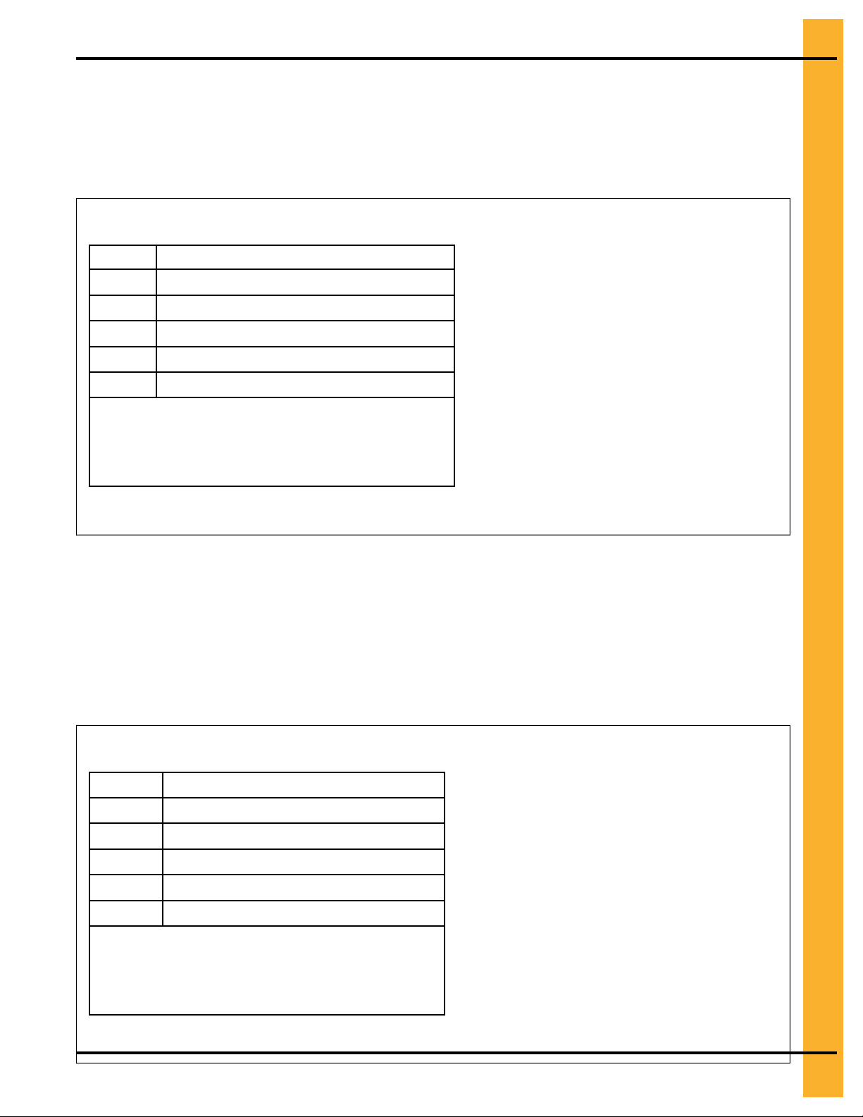
Chapter 6: Stiffeners
Close-Punch Connection for a Two-Ring Stiffener (0–14 Ga) to a Base Stiffener (2–8 Ga)
Reference the following information when connecting a two-ring stiffener (CTS-2073XX) to a base stiffener
(CTS-2119XX).
Figure 6-15 Two-Ring Stiffener (0–14 Ga) to a Two-Ring Stiffener (2–8 Ga) Close-Punch Connection
A
B
C Splice (CTS-2091XX)
D
E
F
NOTE: Two-post stiffeners shown. The bolt pattern will
Close-punch two-ring stiffener (CTS-2073XX)
Close-punch base stiffener (CTS-2119XX)
3/8 x 1 Bolt (S-7485)
3/8 Nut (S-9426)
Completed assembly
vary for three-post. Only place bolts where holes
in the stiffeners align with holes in the sidewall
sheet.
Two-Ring Stiffener (0–14 Ga) to a Base Stiffener (10–16 Ga) Connection
Reference the following information when connecting a two-ring stiffener (CTS-2063XX) to a base stiffener
(CTS-2123XX).
Figure 6-16 Two-Ring Stiffener (0–14 Ga) to a Base Stiffener (10–16 Ga) Connection
A
B
C Splice (CTS-2091XX)
D
E 3/8 Nut (S-9426)
F Completed assembly
NOTE: Two-post stiffeners shown. The bolt pattern will
Pneg-4090A 90 Ft Diameter 40-Series Bin
Two-ring stiffener (CTS-2063XX)
Base stiffener (CTS-2123XX)
3/8 x 1 Bolt (S-7485)
vary for three-post. Only place bolts where
holes in the stiffeners align with holes in the
sidewall sheet.
55
Page 56
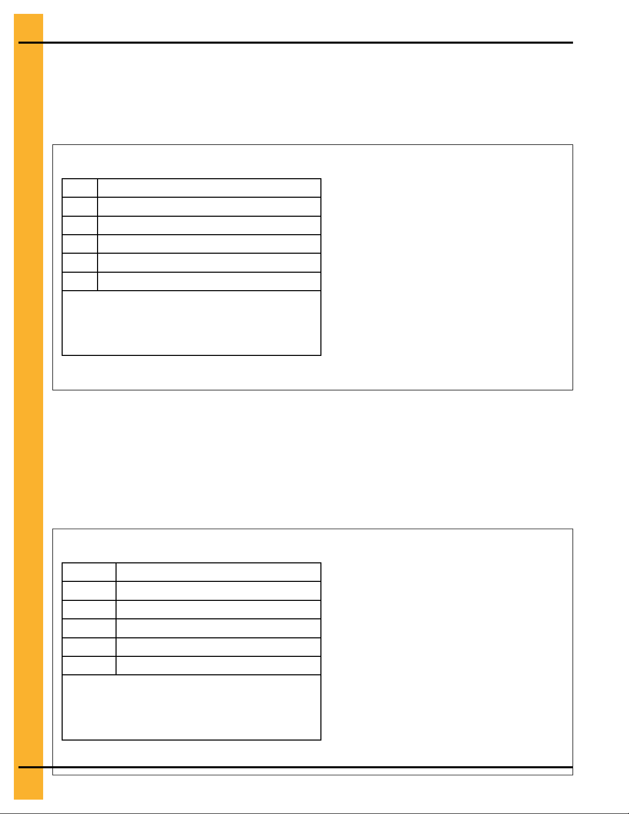
Chapter 6: Stiffeners
Two-Ring Stiffener (2–14 Ga) to a Base Stiffener (10–16 Ga) Connection
Reference the following information for a close-punch connection of a two-ring stiffener (CTS-2073XX) to a
base stiffener (CTS-2115XX).
Figure 6-17 Two-Ring Stiffener (2–14 Ga) to a Base Stiffener (10–16 Ga) Close-Punch Connection
A Close-punch two-ring stiffener (CTS-2073XX)
B Close-punch base stiffener (CTS-2115XX)
C Splice (CTS-2091XX)
D 3/8 x 1 Bolt (S-7485)
E
3/8 Nut (S-9426)
F
Completed assembly
NOTE: Two-post stiffeners shown. The bolt pattern will
vary for three-post. Only place bolts where
holes in the stiffeners align with holes in the
sidewall sheet.
Two-Ring Stiffener (15–16 Ga) to a Base Stiffener (10–16 Ga) Connection
Reference the following information when connecting a two-ring stiffener (CTS-2064XX) to a base stiffener
(CTS-2123XX).
Figure 6-18 Two-Ring Stiffener (15–16 Ga) to a Base Stiffener (10–16 Ga) Connection
A
B
C Splice (CTS-2091XX)
D
E
F
NOTE: Two-post stiffeners shown. The bolt pattern will
Two-ring stiffener (CTS-2064XX)
Base stiffener (CTS-2123XX)
3/8 x 1 Bolt (S-7485)
3/8 Nut (S-9426)
Completed assembly
vary for three-post. Only place bolts where
holes in the stiffeners align with holes in the
sidewall sheet.
56 Pneg-4090A 90 Ft Diameter 40-Series Bin
Page 57

Chapter 6: Stiffeners
Close-Punch Connection for a Two-Ring Stiffener (16 Ga) to a Base Stiffener (10–16 Ga)
Reference the following information for a close-punch connection of a two-ring stiffener (CTS-2075XX) to a
base stiffener (CTS-2115XX).
Figure 6-19 Two-Ring Stiffener (16 Ga) to a Base Stiffener (10–16 Ga) Close-Punch Connection
A Close-punch two-ring stiffener
(CTS-2075XX)
B
C Splice (CTS-2091XX)
D
E
F
NOTE: Two-post stiffeners shown. The bolt pattern will
Close-punch base stiffener (CTS-2115XX)
3/8 x 1 Bolt (S-7485)
3/8 Nut (S-9426)
Completed assembly
vary for three-post. Only place bolts where
holes in the stiffeners align with holes in the
sidewall sheet.
Pneg-4090A 90 Ft Diameter 40-Series Bin
57
Page 58

Chapter 6: Stiffeners
Close-Punch Two-Ring Stiffener (2–14 Ga) to a Laminated Stiffener (2 Ga) with an Insert (10–14 Ga)
Reference the following information for a close-punch connection with a two-ring stiffener (CTS-2073XX)
to a laminated stiffener (CTS-2114XX) and insert (CTS-2113XX).
Figure 6-20 Close-Punch Two-Ring Stiffener to a Laminated Stiffener with an Insert
A Close-punch two-ring stiffener (CTS-2073XX)
B Close-punch laminated stiffener
(CTS-2114XX)
C Insert (CTS-2113XX)
D
NOTE: Two-post stiffeners shown. The bolt pattern will
3/8 x 1 Bolt (S-7485)
E
3/8 Nut (S-9426)
F
Completed assembly
vary for three-post. Only place bolts where
holes in the stiffeners align with holes in the
sidewall sheet.
Close-Punch Laminated Stiffeners (2 Ga) with Inserts (10–14 Ga)
Reference the following information for a close-punch connection of a laminated stiffener (CTS-2079XX) to
a laminated stiffener (CTS-2081XX).
Figure 6-21 Close-Punch Laminated Stiffeners with Inserts
A
B
C 3/8 x 1 Bolt (S-7485)
D 3/8 Nut (S-9426)
E Completed assembly
NOTE: Two-post stiffeners shown. The bolt pattern will
58 Pneg-4090A 90 Ft Diameter 40-Series Bin
Close-punch laminated stiffener
(CTS-2079XX)
Close-punch insert (CTS-2081XX)
vary for three-post. Only place bolts where
holes in the stiffeners align with holes in the
sidewall sheet.
Page 59

Chapter 6: Stiffeners
Close-Punch Laminated Stiffener (2 Ga) with an Insert (10–14 Ga) to a Laminated Base Stiffener (2–5 Ga) with a Base Insert (2–14 Ga)
Reference the following information for a close-punch connection of a two-ring stiffener (CTS-2079XX and
CTS-2081XX) to a laminated base stiffener and insert (CTS-2114XX and CTS-2113XX).
Figure 6-22 Close-Punch Laminated Stiffener with an Insert to a Laminated Base Stiffener with a Base Insert
A Close-punch laminated stiffener (CTS-2079XX)
B Close-punch insert (CTS-2081XX)
C Close-punch laminated base stiffener (CTS-
2114XX)
D
Close-punch base insert (CTS-2113XX)
E
3/8 x 1 Bolt (S-7485)
F
3/8 Nut (S-9426)
G Completed assembly
NOTE: Two-post stiffeners shown. The bolt pattern will
vary for three-post. Only place bolts where holes
in the stiffeners align with holes in the sidewall
sheet.
Pneg-4090A 90 Ft Diameter 40-Series Bin 59
Page 60

Chapter 6: Stiffeners
Base Stiffener (10–16 Ga) to a Base Boot Connection
Reference the following information when connecting a base stiffener (CTS-2123XX) to a base boot (CTS2121XX).
Figure 6-23 Base Stiffener (10–16 Ga) to a Base Boot Connection
A
B
C 3/8 x 1 Bolt (S-7485)
D
E
NOTE: Two-post stiffeners shown. The bolt pattern will
Base stiffener (CTS-2123XX)
Base boot (CTS-2121XX)
3/8 Nut (S-9426)
Completed assembly
vary for three-post. Only place bolts where
holes in the stiffeners align with holes in the
sidewall sheet.
Close-Punch Connection for a Base Stiffener (10–16 Ga) to a Base Boot
Reference the following information for a close-punch connection for a base stiffener (CTS-2115XX) to a
base boot (CTS-2121XX).
Figure 6-24 Base Stiffener (10–16 Ga) to a Base Boot Close-Punch Connection
A
B
C 3/8 x 1 Bolt (S-7485)
D
E
NOTE: Two-post stiffeners shown. The bolt pattern will
60 Pneg-4090A 90 Ft Diameter 40-Series Bin
Close-punch base stiffener (CTS-2115XX)
Close-punch base boot (CTS-2121XX)
3/8 Nut (S-9426)
Completed assembly
vary for three-post. Only place bolts where
holes in the stiffeners align with holes in the
sidewall sheet.
Page 61

Chapter 6: Stiffeners
Close-Punch Connection for a Base Stiffener (2+2 Ga – 8 Ga) to a Base Boot
Reference the following information for a close-punch connection for a base stiffener (CTS-2119XX) to a
base boot (CTS-2110XX).
Figure 6-25 Base Stiffener (2+2 Ga – 8 Ga) to a Base Boot Close-Punch Connection
A Close-punch base stiffener (CTS-2119XX)
B Close-punch base Boot (CTS-2110XX)
C 3/8 x 1 Bolt (S-7485)
D 3/8 Nut (S-9426)
E
NOTE: Two-post stiffeners shown. The bolt pattern will
Completed assembly
vary for three-post. Only place bolts where
holes in the stiffeners align with holes in the
sidewall sheet.
Pneg-4090A 90 Ft Diameter 40-Series Bin 61
Page 62

Chapter 6: Stiffeners
Close-Punch Laminated Base Stiffener (2 Ga) with Insert (2+14 to 2+10 Ga) to a Base Boot
Reference the following information when connecting a close-punch laminated base stiffener
(CTS-2114XX) to a base boot (CTS-2109XX or CTS-2110XX).
Figure 6-26 Close-Punch Laminated Base Stiffener to a Base Boot
A Close-punch laminated base stiffener (CTS-
2114XX)
B
Close-punch base Insert (CTS-2113XX)
C Close-punch base boot (CTS-2109XX or CTS-
2110XX)
D 3/8 x 1 Bolt (S-7485)
E 3/8 Nut (S-9426)
F Completed assembly
NOTE: Two-post stiffeners shown. The bolt pattern will
vary for three-post. Only place bolts where holes in
the stiffeners align with holes in the sidewall sheet.
Close-Punch Standard Stiffener to a 12–Bolt Pattern Laminated Stiffener with Insert
Reference the following information for a close-punch connection of a standard stiffener (CTS-2073) to a
12–bolt pattern laminated stiffener (CTS-2137XX) with insert (CTS-2138XX).
Figure 6-27 Close-Punch Standard Stiffener to a 12–Bolt Pattern Laminated Stiffener with Insert
A
Close punch standard stiffener (CTS-2073XX)
B
Close-punch laminated stiffener (CTS-2137XX)
C Close-punch insert (CTS-2138XX)
D
3/8 x 1 Bolt (S-7485)
E
3/8 Nut (S-9426)
F
Completed assembly
NOTE: Two-post stiffeners shown. The bolt pattern will
vary for three-post. Only place bolts where holes in
the stiffeners align with holes in the sidewall sheet.
62 Pneg-4090A 90 Ft Diameter 40-Series Bin
Page 63

Chapter 6: Stiffeners
12–Bolt Pattern Close-Punch Laminated Stiffeners with Insert
Reference the following information for a close-punch connection of two 12–bolt pattern laminated stiffeners (CTS-2137XX) with an inserts (CTS-2138XX).
Figure 6-28 Close-Punch 12–Bolt Pattern Laminated Stiffeners with Insert
A
Close-punch laminated stiffener (CTS-2137XX)
B
Close-punch Insert (CTS-2138XX)
C 3/8 x 1 Bolt (S-7485)
D
3/8 Nut (S-9426)
E
Completed assembly
NOTE: Two-post stiffeners shown. The bolt pattern will
vary for three-post. Only place bolts where holes
in the stiffeners align with holes in the sidewall
sheet.
Pneg-4090A 90 Ft Diameter 40-Series Bin 63
Page 64
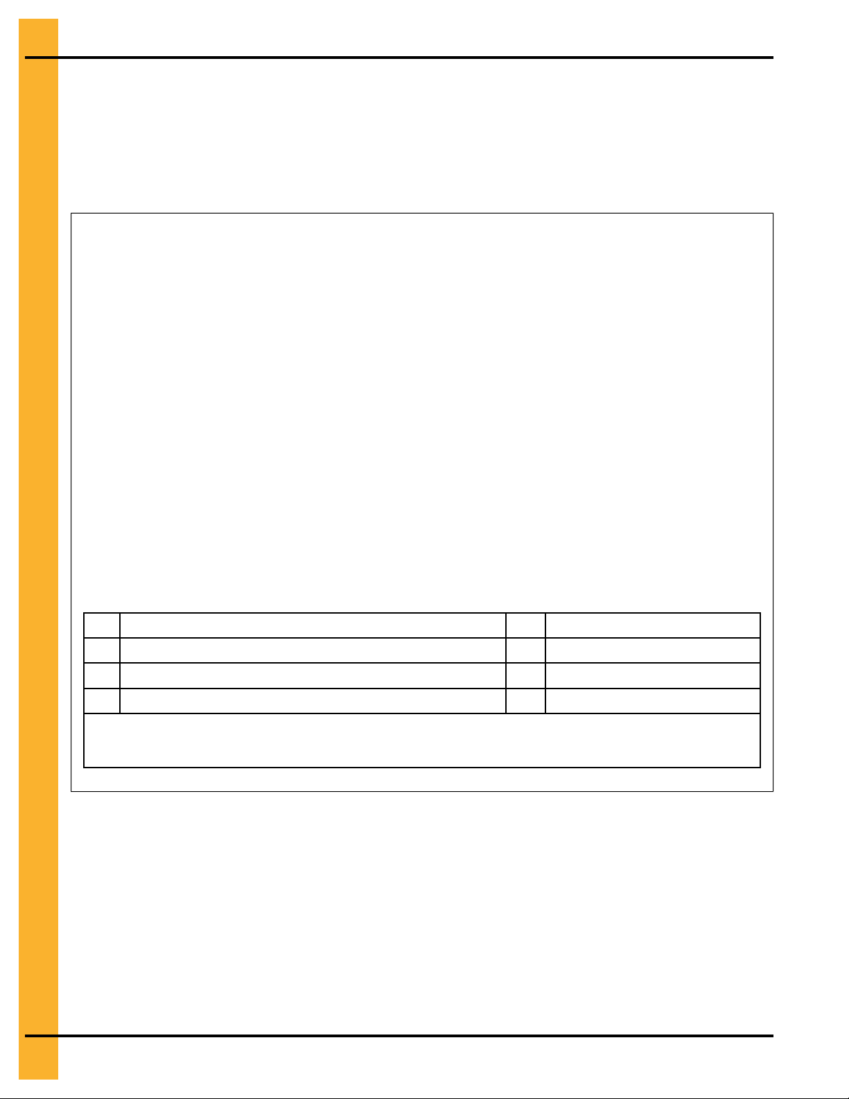
Chapter 6: Stiffeners
Close-Punch 12–Bolt Pattern Laminated Stiffener to Laminated Base Stiffener with an Inserts to a Base Boot
Reference the following information for a close-punch connection of a 12–bolt pattern laminated stiffener
(CTS-2137) to a laminated base stiffener (CTS-2135XX) with a inserts (CTS-2138XX and CTS-2135XX) to
a base boot (CTS-2131XX).
Figure 6-29 Laminated Stiffener to Laminated Base Stiffener with an Inserts to a Base Boot
A Close-punch laminated stiffener (CTS-2137XX) E Base boot (CTS-2131XX)
B Close-punch base Insert (CTS-2138XX) F 3/8 x 1 Bolt (S-7485)
C Close-punch laminated base stiffener (CTS-2135XX) G 3/8 Nut (S-9426)
D Close-punch base Insert (CTS-2136XX) H Completed assembly
NOTE: Two-post stiffeners shown. The bolt pattern will vary for three-post. Only place bolts where holes in
the stiffeners align with holes in the sidewall sheet.
64 Pneg-4090A 90 Ft Diameter 40-Series Bin
Page 65

Chapter 6: Stiffeners
Close-Punch 12–Bolt Pattern Laminated Stiffener to Laminated Base Stiffener with an Inserts to a Base Boot
Reference the following information for a close-punch connection of a 12–bolt pattern laminated stiffener
(CTS-2137) to a laminated base stiffener (CTS-2133XX) with a inserts (CTS-2138XX and CTS-2134XX) to
a base boot (CTS-2109XX or CTS-2110XX).
Figure 6-30 Laminated Stiffener to Laminated Base Stiffener with an Inserts to a Base Boot
A Close-punch laminated stiffener (CTS-2137) E Base boot (CTS-2109XX or 2110XX)
B Close-punch base Insert (CTS-2138XX) F 3/8 x 1 Bolt (S-7485)
C Close-punch laminated base stiffener (CTS-
2133XX)
D
Close-punch base Insert (CTS-2134XX)
NOTE: Two-post stiffeners shown. The bolt pattern will vary for three-post. Only place bolts where holes in
the stiffeners align with holes in the sidewall sheet.
G 3/8 Nut (S-9426)
H
Completed assembly
Pneg-4090A 90 Ft Diameter 40-Series Bin 65
Page 66

Chapter 6: Stiffeners
All information, illustrations, photos, and specifications in this manual are based on the latest
information available at the time of publication. The right is reserved to make changes at any
time without notice.
66 Pneg-4090A 90 Ft Diameter 40-Series Bin
Page 67

7 Roof Assembly
Topics Covered in this Chapter
▪ Attaching the Inside Stiffener to the Top Outside Stiffener
▪ Attaching the Eave Bracket to the Inside Stiffener
▪ Attaching the Eave Angle to the Sidewall Sheet
▪ Connecting the Tension Member to the Eave Bracket
▪ Assembling a Laminated Rafter
▪ Assembling the Rafters
▪ Attaching the Center Collar Rafter Clips to the Rafter
▪ About Temperature Cable Brackets and A-Frame Assemblies
▪ Assembling the Temperature Cable Bracket
▪ Attachment Locations of Purlins to Rafters
▪ Assembling Purlin Number 6
▪ Assembling Purlin Number 5
▪ Assembling Purlin Number 4
▪ Assembling Purlin Number 3
▪ Assembling Purlin Number 2
▪ Assembling Purlin Number 1
▪ Assembling the Center Collar
▪ Center Collar Placement
▪ Guidelines for Assembling and Lifting the A-Frame Rafter Sections
▪ Attaching the A-Frames to the Center Collar
▪ Attaching the A-Frame to the Eave Bracket
▪ Assembling the Roof Panel Clips
▪ Installing the 6–Hole Intermediate Purlins
▪ Installing the 4–Hole Intermediate Purlins
▪ Attaching the Roof Panels
▪ Installing the Roof Flashing
▪ Assemble and Install Center Collar Channels and Cap Plates
▪ Installing the Conveyor Support Brackets to the Peak Cap
Attaching the Inside Stiffener to the Top Outside Stiffener
The inside stiffener supports the eave bracket. It is installed to the inside perimeter of the sidewall sheet at
the same time as the top outside stiffener. Two-post sidewall sheets will have two inside stiffeners per
sheet and three-post sidewall sheets will have three inside stiffeners per sheet. The inside stiffeners are
only located at the eave bracket locations in the sidewall sheet.
What You Should Know
NOTE: Do not tighten the nuts (C) until all hardware has been installed attaching the inside stiffener (CTS–
2069XX) to the sidewall and the outside stiffener. Bins with an odd number of rings will use the
one-ring outside stiffener (CTS-2071XX), and bins with an even number of rings will use the tworing outside stiffener (CTS-2111XX or CTS-2116XX).
Pneg-4090A 90 Ft Diameter 40-Series Bin 67
Page 68
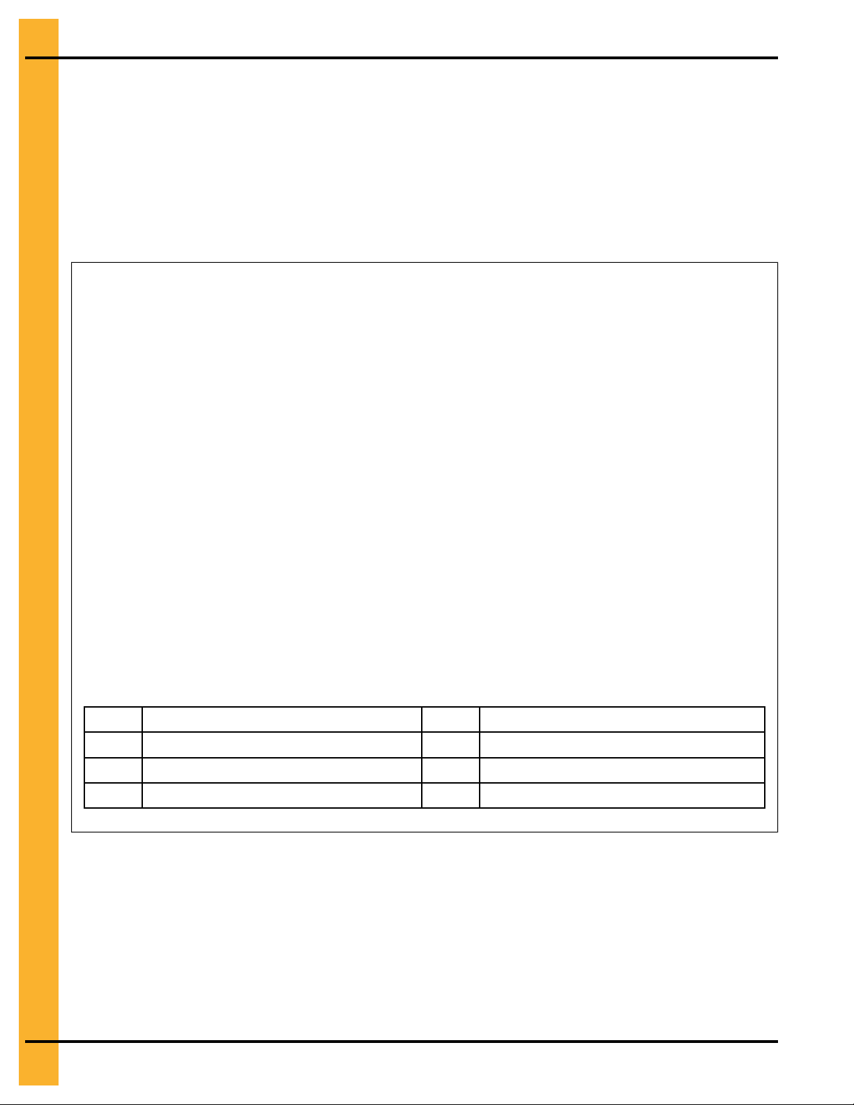
Chapter 7: Roof Assembly
1. From the inside perimeter of the sidewall, place the bolt (B) through the hole located approximately 4
in. down from the top of the sidewall sheet (A).
NOTE: Install the bolts from the inside to the outside of the bin, passing through the inside stiffener,
corrugation spacer, sealing washer, sidewall sheet, and outside stiffener and flange nut.
2. On the inside perimeter, install a sealing washer (F), corrugation spacer (E), and inside stiffener (D).
3. Install a flange nut (C) to the bolt (B) and repeat this process with the remaining hardware. Tighten
hardware to the recommended torque specifications, see Bolt Torque Specifications, page 24.
Figure 7-1 Inside stiffener to the one-ring top stiffener for bins with an odd number of rings
A Sidewall E Corrugation spacer (S-7041)
B 3/8 x 1-1/2 in. flange bolt (S-7488) F Sealing washer (S-3558)
C 3/8 in. flange nut (S-9426) G One-ring top stiffener (CTS-2071XX)
D Inside stiffener (CTS-2069XX) H Assembled view
68 Pneg-4090A 90 Ft Diameter 40-Series Bin
Page 69
Chapter 7: Roof Assembly
Figure 7-2 Inside stiffener to the two-ring top stiffener for bins with an even number of rings
A Sidewall E Corrugation spacer (S-7041)
B 3/8 x 1-1/2 in. flange bolt (S-7488) F Sealing washer (S-3558)
C 3/8 in. flange nut (S-9426) G Two-ring top stiffener (CTS-2111XX or CTS-
2116XX)
D
Inside stiffener (CTS-2069XX)
H Assembled view
After You Finish
Repeat this process for the remaining inside stiffeners.
Pneg-4090A 90 Ft Diameter 40-Series Bin 69
Page 70
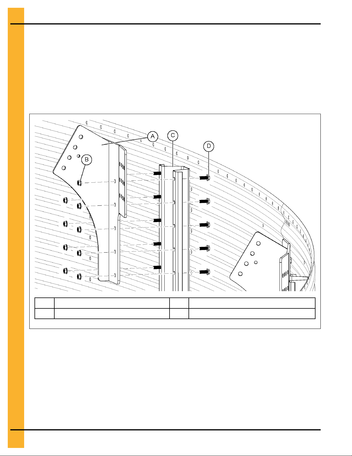
Chapter 7: Roof Assembly
Attaching the Eave Bracket to the Inside Stiffener
Eave brackets secure the roof rafter to the sidewall.
Before You Begin
Install the inside stiffeners to the sidewalls before proceeding.
1. Attach the eave bracket (A) to the inside stiffener (C) and install flange bolts (D).
2. Install flange nuts (B) to the eave bracket and tighten to the recommended torque specifications. See
Bolt Torque Specifications, page 24.
Figure 7-3 View from inside of the sidewall of a bin
A Eave bracket (CTR-0429) C Inside stiffener (CTS-2069XX)
B 3/8 in. flange nut (S-9426) D 3/8 x 1 in. flange bolt (S-7485)
After You Finish
Repeat this process for the remaining eave brackets.
70 Pneg-4090A 90 Ft Diameter 40-Series Bin
Page 71

Chapter 7: Roof Assembly
Attaching the Eave Angle to the Sidewall Sheet
The eave angle secures each lower portion of the roof panels.
What You Should Know
Eave angles are bolted to the inside portion of the sidewall and will overlap each section.
1. Install the optional eave seal (F) along the top edge of the eave angle (A).
2. Locate the eave bracket (H) and align the holes of the first eave angle (A) with the holes of the onering top stiffener (I).
IMPORTANT: For a sidewall sheet that spans four roof panels, the eave angle will align from inside
stiffener to inside stiffener. This is very important to ensure the roof panels align properly with the rafters.
3. Install flange bolts (D) and flange nuts (B), leaving the end holes open.
NOTE: The quantity of flange bolts (D) and flange nuts (B) may vary, depending on the sidewall
punch pattern.
4. Install the second eave angle (C) overlapping the first eave angle (A).
5. Install the flange bolts (D) and flange nuts (B), leaving the last hole open for the next eave angle to
be installed.
NOTE: The quantity of flange bolts (D) and flange nuts (B) may vary, depending on the sidewall
punch pattern.
6. Bend the eave angle tabs (G) upward to conform with each roof panel rib.
7. Tighten all hardware to the recommended torque specification. See Bolt Torque Specifications, page
24.
Pneg-4090A 90 Ft Diameter 40-Series Bin 71
Page 72
Chapter 7: Roof Assembly
Figure 7-4 Exploded view of eave angle (four roof panels)
A First eave angle (CTR-0187) H Eave bracket (CTR-0429)
B 5/16 in. flange nut (S-3611) I Outside top stiffener
C Second eave angle (CTR-0187) J Inside stiffener (CTS-2069XX)
D 5/16 x 1 in. flange bolt (S-10260) K Top of the top sidewall sheet
E Upper sidewall L Bottom of the top sidewall sheet
G
Eave angle tab M
F
Optional eave seal (CRP-4800)
Sidewall hole (For the first hole or the last hole of
the eave angle and inside stiffener).
After You Finish
Continue this procedure for the remaining eave angles.
72 Pneg-4090A 90 Ft Diameter 40-Series Bin
Page 73

Chapter 7: Roof Assembly
Connecting the Tension Member to the Eave Bracket
Tension members connect to the eave brackets and are installed around the inside of the bin eave.
Before You Begin
Ensure all eave angles, inside stiffeners and eave brackets are installed before proceeding.
What You Should Know
IMPORTANT: Install bolts as shown, from the backside of the eave bracket.
1. Lift and support two tension members (D and F), and install to each side of the eave bracket (B).
2. Install flange bolts (C) and flange nuts (A) to each end of the tension members (D and F).
3. Tighten to the recommended torque specifications. See Bolt Torque Specifications, page 24.
Figure 7-5 View of the tension plate mounting to the bin eave bracket
A 1/2 in. flange nut (S-10253) D Tension member (CTR-0439)
B Eave bracket (CTR-0429) E Eave angle (CTR-0187)
C 1/2 x 1-3/4 in. flange bolt (S-10252) F Tension member (CTR-0439)
After You Finish
Repeat this process for the remaining tension members.
Pneg-4090A 90 Ft Diameter 40-Series Bin 73
Page 74

Chapter 7: Roof Assembly
Assembling a Laminated Rafter
Laminated rafters nest together to give additional strength and should be assembled before attaching the
upper and lower rafters.
What You Should Know
All the lower rafters are assembled with rafter inserts.
1. Place the lower rafter (A) against the mating surface of the rafter insert (B), and install flange bolts (C)
and flange nuts (D).
NOTE: The top flange of the rafter insert is positioned underneath the top flange of the rafter.
2. Tighten all the hardware to the recommended torque specification. See Bolt Torque Specifications,
page 24.
Figure 7-6 Laminated rafter
A
Lower rafter (CTR-0436) C 1/2 x 1-3/4 in. flange bolt (S-10252)
B
Rafter insert (CTR-0438)
After You Finish
Repeat this process for the remaining laminated lower rafters.
D
1/2 in. flange nut (S-10253)
Assembling the Rafters
For the larger bins (90–105 ft.) each rafter will consist of a two piece design and will need to be spliced
together for assembling the A-frames.
1. Locate an upper rafter (A) and a lower rafter (B), and find the series of twelve holes on each end of
the upper rafter (A) and a lower rafter (B).
NOTE: Assemble rafters with the flanges facing in the same direction.
2. Place the lower rafter (B) to the outside mating surface of the upper rafter (A), and align the series of
twelve holes together.
3. Install flange bolts (C) and flange nuts (D), and tighten hardware to the recommended torque specifications. See Bolt Torque Specifications, page 24.
74 Pneg-4090A 90 Ft Diameter 40-Series Bin
Page 75

Chapter 7: Roof Assembly
Figure 7-7 A-frame assembly (Note: complete A-frame assembly shown for clarity)
A
Upper rafter (CTR-0437) C 1/2 x 1-3/4 in. flange bolt (S-10252)
B
Lower rafter (CTR-0436 and CTR-0438)
After You Finish
Repeat this procedure for the remaining rafters.
D
1/2 in. flange nut (S-10253)
Pneg-4090A 90 Ft Diameter 40-Series Bin
75
Page 76

Chapter 7: Roof Assembly
Attaching the Center Collar Rafter Clips to the Rafter
Center collar rafter clips secure the A-frame rafter sections to the center collar.
What You Should Know
Each assembled roof rafter receives two center collar rafter clips, identified as the left center collar rafter
clip (D) and the right center collar rafter clip (E).
1. Determine the correct orientation of each rafter (A) by identifying the roof panel holes (B) located
near the end of each rafter.
2. Install the left center collar rafter clip (D) and right center collar rafter clip (E) to each side of the roof
rafter (A).
3. Use flange bolts (F) and flange nuts (C) to secure the center collar rafter clips (D and E) to the rafter
(A). Tighten to the recommended torque specification. See Bolt Torque Specifications, page 24.
Figure 7-8 Exploded view of center collar rafter clips
A
Roof rafter
B
Roof panel hole
C 1/2 in. flange nut (S-10253)
D
Left center collar rafter clip (CTR-0442)
E
Right center collar rafter clip (CTR-0443)
F
1/2 x 1-3/4 in. flange bolt (S-10252)
After You Finish
Repeat this process for the remaining roof rafters.
76 Pneg-4090A 90 Ft Diameter 40-Series Bin
Page 77

Chapter 7: Roof Assembly
About Temperature Cable Brackets and A-Frame Assemblies
Temperature cable bracket installation locations must be considered prior to assembling the A-frames.
Installation Locations for Temperature Cable Brackets
Before assembling the A-frames, you must know the installation locations of the temperature cable brackets within the A-frame assemblies. Temperature cable brackets are installed at the same time as the purlins are installed.
This information is provided solely for the purpose of facilitating proper support bracket placement. It is
fully the responsibility of the dealer, customer, contractor, or said agent of such parties to confirm the
details of the system to be used. GSI is not responsible for the effectiveness or performance of any temperature cable monitoring system or layout.
IMPORTANT: Temperature cable brackets must be installed at the specified locations as shown below.
Any variation from this pattern or cable quantity shown must be reviewed by GSI engineering. This must be reviewed well in advance of the bin order.
Lifting Sequence for the A-Frame Assemblies
The layout of the roof structure consists of standard A-frame assemblies and A-frame assemblies with Xbracing that are installed in a specific sequence to evenly distribute the weight as they are being installed.
The A-frames with X-bracing are strategically spaced around the diameter of the bin and are the first Aframes to be installed. The A-frame assemblies can be installed in the order as shown in the figure below.
A-frames are installed across from each other to keep the weight distributed evenly during installation.
Tip
Label each A-frame assembly according to the order it is to be installed as it is assembled.
Pneg-4090A 90 Ft Diameter 40-Series Bin
77
Page 78

Chapter 7: Roof Assembly
Figure 7-9 A-frame installation sequence and temperature cable locations for 90 ft diameter bin
A
5 ft radius location (center collar) C 35.5 ft radius location
B
14.8 ft radius location
78 Pneg-4090A 90 Ft Diameter 40-Series Bin
Page 79

Chapter 7: Roof Assembly
Table 7-1 A-frame installation sequence and temperature cable locations for 90 ft diameter bin
A-frame number Rafter Number
A1
A2
A3
A4
A5
A6
A7
A8
A9
A10
A11
A12
A13
A14
A15
NA Attach to center collar
R1 T16 35.5 ft
R2 T2 14.8 ft
R19 T12 35.5 ft
R20 T5 14.8 ft
R13 T10 35.5 ft
R14 T4 14.8 ft
R7 T8 35.5 ft
R8 T3 14.8 ft
R25 T14 35.5 ft
R26 T6 14.8 ft
R23
R24
R5
R6
R15
R16 T11 35.5 ft
R27
R28 T15 35.5 ft
R29
R30
R11
R12
R17
R18
R3
R4 T7 35.5 ft
R9
R10 T9 35.5 ft
R21
R22 T13 35.5 ft
Temp Cable Number
— —
— —
— —
— —
— —
— —
— —
— —
— —
— —
— —
— —
— —
— —
— —
T1 5 ft
Radius Location
NOTE: A-frames labeled “A1” through “A5” have X-bracing and are installed first. A-frames labeled “A6”
through “A15” are standard A-frames. The empty spaces that are not labeled must have purlins
installed between the rafters after all the A-frames are secured. The numbers reflect the recommended installation sequence of the A-frame assemblies.
Table 7-2 Starting lengths for temperature cables for 90 ft diameter bins
Length from the center collar 268.9 in. (683.01 cm)
Length from 14.8 ft diameter location 202.1 in. (513.33 cm)
Length from 35.5 ft diameter location 55.4 in. (140.72 cm)
Pneg-4090A 90 Ft Diameter 40-Series Bin 79
Page 80

Chapter 7: Roof Assembly
The temperature cable lengths in the chart above are the distances from where the temperature cable
attaches to the rafter or the center collar to the top ring. To calculate the correct temperature cable length,
add 32 inches for each bin ring to the starting length. Temperature cables must terminate above any
unload equipment and be secured in place with twine. DO NOTallow cables to become tangled in unload
equipment.
80 Pneg-4090A 90 Ft Diameter 40-Series Bin
Page 81

Chapter 7: Roof Assembly
Assembling the Temperature Cable Bracket
The temperature cable brackets are installed to the roof rafters and support the temperature cables.
Before You Begin
Determine the correct location of the temperature cable brackets within the structure of the A-frame
Assembly. See About Temperature Cable Brackets and A-Frame Assemblies, page 77.
What You Should Know
The A-frame assembly consists of two roof rafters, purlin clips, purlins and possibly X-bracing. The temperature cable brackets should be installed when the A-frames are assembled.
NOTE: The temperature cable bracket must be installed at specific locations, see About Temperature
Cable Brackets and A-Frame Assemblies, page 77.
1. Attach a right purlin clip (C), a left purlin clip (D) and a temperature cable bracket (B) to the roof rafter
(A), and install two flange bolts (E) and two flange nuts (F).
NOTE: If no X-bracing is installed, install three flange bolts (E) and three flange nuts (F).
2. After all purlins and X-bracing are installed in the A-frame, tighten all hardware to the recommended
torque specifications. See Bolt Torque Specifications, page 24.
Pneg-4090A 90 Ft Diameter 40-Series Bin 81
Page 82

Chapter 7: Roof Assembly
Figure 7-10 Installing a temperature cable bracket
A
B
C Right purlin clip (CTR-0100)
Roof rafter
10 in. temperature cable bracket (CTR-0013)
D
Left purlin clip (CTR-0099)
E
1/2 x 1-3/4 in. flange bolt (S-10252)
F
1/2 in. flange nut (S-10253)
3. Install a quick link (C) to each cable bracket (B) to support the temperature cables.
IMPORTANT: Do not attach weights to the temperature cables; secure the bottom of cables to the
floor with light twine. No roof rafter shall support more than one cable.
82 Pneg-4090A 90 Ft Diameter 40-Series Bin
Page 83

Figure 7-11 Supplier quick link
Chapter 7: Roof Assembly
A Purlin
B Temperature cable bracket (CTR-0013)
C Supplier quick link
4. Locate the center collar temperature cable hole (D), and install a supplier quick link (C), allowing for
the installation of a temperature cable at this location.
Figure 7-12 Supplier quick link on the center collar (view from bottom side of center collar)
C Supplier quick link
Pneg-4090A 90 Ft Diameter 40-Series Bin 83
D
Center collar temperature cable hole
Page 84

Chapter 7: Roof Assembly
Attachment Locations of Purlins to Rafters
Purlins are horizontal members between the rafters that give support to the roof structure. The length of
the purlin determines its location on the A-frame assembly.
The following reference depicts a completely assembled A-frame roof rafter section with X-bracing
installed. For more information, see the following sections: Assembling Purlin Number 1, page 95, Assem-
bling Purlin Number 2, page 93, Assembling Purlin Number 3, page 91, Assembling Purlin Number 4,
page 89, Assembling Purlin Number 5, page 87, and Assembling Purlin Number 6, page 85.
Figure 7-13 Location of purlins for a 90 ft (27.4 m) diameter bins
A
Location of purlin number 1 (CTR-0430)
B
Location of purlin number 2 (CTR-0431)
C Location of purlin number 3 (CTR-0432)
84 Pneg-4090A 90 Ft Diameter 40-Series Bin
D
Location of purlin number 4 (CTR-0433)
E
Location of purlin number 5 (CTR-0434)
F
Location of purlin number 6 (CTR-0435)
Page 85

Chapter 7: Roof Assembly
Assembling Purlin Number 6
Purlin number 6 is located sixth purlin from the eave.
Before You Begin
Place two roof rafters on the ground with roof panel holes facing up.
NOTE: Temperature cables may also be installed at this location, to determine if temperature cable brack-
ets will be needed, see About Temperature Cable Brackets and A-Frame Assemblies, page 77.
What You Should Know
The A-frame roof rafter section consists of two roof rafters identified as the left-hand roof rafter (A) and the
right-hand roof rafter (C).
There are also two different purlin clips, a left purlin clip (E) and a right purlin clip (D). The left purlin clip
has an extra hole located in the center as compared to the right, which only has six holes where the purlin
and purlin clip are bolted together.
IMPORTANT: Do not drill additional holes in the purlin. Install the flange bolts and flange nuts as dictated
by the number of holes in the purlin.
NOTE: The seventh hole located in the center of the left purlin clip (E) is for identification purposes only.
No hardware is used in this location.
1. Attach a left purlin clip (E) and a right purlin clip (D) to the right-hand roof rafter (C), and install three
flange bolts (F) and three flange nuts (I).
2. Attach a left purlin clip (E) and a right purlin clip (D) to the left-hand roof rafter (A), and install three
flange bolts (F) and three flange nuts (I).
3. Install the purlin (H) to the right purlin clip (D) and the left purlin clip (E) located between the left-hand
roof rafter (A) and the right-hand roof rafter (C).
NOTE: Ensure that the orientation of the purlin is correct, the roof panel holes are facing up, and the
notch in the purlin is facing the right-hand roof rafter (C).
4. Install eight flange bolts (B) and eight flange nuts (G), securing the purlin to the purlin clips.
5. After all purlins are installed in the A-frame, tighten hardware to the recommended torque specifications. See Bolt Torque Specifications, page 24.
Pneg-4090A 90 Ft Diameter 40-Series Bin 85
Page 86

Chapter 7: Roof Assembly
Figure 7-14 Purlin location 6
A
Left-hand roof rafter (CTR-0437)
B
1/2 x 1-3/4 in. flange bolt (S-10252) G 1/2 in. flange nut (S-10253)
C Left-hand roof rafter (CTR-0437)
D
Right purlin clip (CTR-0100)
E
Left purlin clip (CTR-0099)
F
1/2 x 1-3/4 in. flange bolt (S-10252)
H
Purlin (CTR-0435)
I
1/2 in. flange nut (S-10253)
86 Pneg-4090A 90 Ft Diameter 40-Series Bin
Page 87

Chapter 7: Roof Assembly
Assembling Purlin Number 5
Purlin number 5 is located fifth purlin from the eave.
Before You Begin
Place two roof rafters on the ground with roof panel holes facing up. Several A-frame assemblies will have
X-bracing installed and be placed periodically throughout the perimeter of the roof. Determine if X-bracing
is being installed and note those steps in this procedure.
NOTE: Temperature cables may also be installed at this location, to determine if temperature cable brack-
ets will be needed, see About Temperature Cable Brackets and A-Frame Assemblies, page 77.
What You Should Know
The A-frame assembly consists of two roof rafters identified as the left-hand roof rafter (A) and the righthand roof rafter (C). The configuration at this location may not be the same on all A-frames, depending if
X-bracing is being installed or not.
There are also two different purlin clips, a left purlin clip (E) and a right purlin clip (D). The left purlin clip
has seven holes, compared to the right, which has six holes along the purlin and purlin clip mating surface.
IMPORTANT: Do not drill additional holes in purlin. Install the flange bolts and the flange nuts as dictated
by the number of holes in the purlin.
NOTE: The seventh hole located in the center of the left purlin clip (E) is for identification purposes only.
No hardware is used in this location.
1. Attach a right purlin clip (D) and a left purlin clip (E) to the right-hand roof rafter (C), and install two
flange bolts (F) and two flange nuts (I) into the two top holes.
NOTE: If no X-bracing is being installed, install three flange bolts (F) and three flange nuts (I) in this
step.
2. Attach a right purlin clip (D) and a left purlin clip (E) to the left-hand roof rafter (A), and install two
flange bolts (F) and two flange nuts (I) into the two bottom holes.
NOTE: If no X-bracing is being installed, install three flange bolts (F) and three flange nuts (I) in this
step.
3. Install the purlin (H) to the right purlin clip (D) and the left purlin clip (E) located between each roof
rafter. Install eight flange bolts (B) and eight flange nuts (G), securing the purlin to the purlin clips.
NOTE: If no X-bracing is being installed, proceed to step 8.
4. Attach the bottom X-brace (K) to the right-hand roof rafter (C), and install a flange bolt (F) and a
flange nut (I) into the bottom hole.
IMPORTANT: For adjustment purposes, DO NOT tighten the X-brace flange bolts until all X-braces
have been installed.
5. Attach the top X-brace (J) to the left-hand roof rafter (A), and install a flange bolt (F) and one flange
nut (I) into the top hole.
6. Secure the bottom portion of each X-brace (J and K) with a flange bolt (F) and one flange nut (I).
7. Install a flange bolt (L) and one flange nut (M) securing the X-braces together where they cross.
8. After all purlins are installed, tighten the hardware to the recommended torque specifications. See
Bolt Torque Specifications, page 24.
Pneg-4090A 90 Ft Diameter 40-Series Bin 87
Page 88

Chapter 7: Roof Assembly
Figure 7-15 Purlin location 5
A Left-hand roof rafter (CTR-0437) H Purlin (CTR-0434)
B
1/2 x 1-3/4 in. flange bolt (S-10252)
C Right-hand roof rafter (CTR-0437)
D
Right purlin clip (CTR-0100)
E
Left purlin clip (CTR-0099)
F
1/2 x 1-3/4 in. flange bolt (S-10252)
G 1/2 in. flange nut (S-10253)
88 Pneg-4090A 90 Ft Diameter 40-Series Bin
I
1/2 in. flange nut (S-10253)
J
Top X-brace (CTR-0040)
K
Bottom X-brace (CTR-0040)
L
1/2 x 1-3/4 in. flange bolt (S-10252)
M
1/2 in. flange nut (S-10253)
Page 89

Chapter 7: Roof Assembly
Assembling Purlin Number 4
Purlin number 4 is located forth purlin from the eave.
Before You Begin
Place two roof rafters on the ground with roof panel holes facing up.
NOTE: Temperature cables may also be installed at this location, to determine if temperature cable brack-
ets will be needed, see About Temperature Cable Brackets and A-Frame Assemblies, page 77.
What You Should Know
The A-frame roof rafter section consists of two roof rafters identified as the left-hand roof rafter (A) and the
right-hand roof rafter (C).
There are also two different purlin clips, a left purlin clip (E) and a right purlin clip (D). The left purlin clip
has seven holes, compared to the right, which has six holes along the purlin and purlin clip mating surface.
IMPORTANT: Do not drill additional holes in purlin. Install the flange bolts and the flange nuts as dictated
by the number of holes in the purlin.
NOTE: The seventh hole located in the center of the left purlin clip (E) is for identification purposes only.
No hardware is used in this location.
1. Attach a right purlin clip (D) and a left purlin clip (E) to the right-hand roof rafter (C), and install two
flange bolts (F) and two flange nuts (I) into the two top holes.
NOTE: If no X-bracing is being installed, install three flange bolts (F) and three flange nuts (I) in this
step.
2. Attach a right purlin clip (D) and a left purlin clip (E) to the left-hand roof rafter (A), and install two
flange bolts (F) and two flange nuts (I) into the two bottom holes.
NOTE: If no X-bracing is being installed, install three flange bolts (F) and three flange nuts (I) in this
step.
3. Install the purlin (H) to the right purlin clip (D) and the left purlin clip (E) located between each roof
rafter. Install eight flange bolts (B) and eight flange nuts (G), securing the purlin to the purlin clips.
NOTE: If no X-bracing is being installed, proceed to step 8.
4. Attach the bottom X-brace (K) to the right-hand roof rafter (C), and install a flange bolt (F) and a
flange nut (I) into the bottom hole.
IMPORTANT: For adjustment purposes, DO NOT tighten the X-brace flange bolts until all X-braces
have been installed.
5. Attach the top X-brace (J) to the left-hand roof rafter (A), and install a flange bolt (F) and one flange
nut (I) into the top hole.
6. Secure the bottom portion of each X-brace (J and K) with a flange bolt (F) and one flange nut (I).
7. Install a flange bolt (L) and one flange nut (M) securing the X-braces together where they cross.
8. After all purlins are installed, tighten the hardware to the recommended torque specifications. See
Bolt Torque Specifications, page 24.
Pneg-4090A 90 Ft Diameter 40-Series Bin 89
Page 90

Chapter 7: Roof Assembly
Figure 7-16 Purlin location 4
A
Left-hand roof rafter (CTR-0437)
B
1/2 x 1-3/4 in. flange bolt (S-10252)
C Right-hand roof rafter (CTR-0437)
D
Right purlin clip (CTR-0100)
E
Left purlin clip (CTR-0099)
F
1/2 x 1-3/4 in. flange bolt (S-10252)
G 1/2 in. flange nut (S-10253)
90 Pneg-4090A 90 Ft Diameter 40-Series Bin
H
Purlin (CTR-0433)
I
1/2 in. flange nut (S-10253)
J
Top X-brace (CTR-0038)
K
Bottom X-brace (CTR-0038)
L
1/2 x 1-3/4 in. flange bolt (S-10252)
M
1/2 in. flange nut (S-10253)
Page 91

Chapter 7: Roof Assembly
Assembling Purlin Number 3
Purlin number 3 is located third from the eave.
Before You Begin
Place two roof rafters on the ground with roof panel holes facing up. Several A-frame assemblies will have
X-bracing installed and be placed periodically throughout the perimeter of the roof. Determine if X-bracing
is being installed and note those steps in this procedure.
NOTE: Temperature cables may also be installed at this location, to determine if temperature cable brack-
ets will be needed, see About Temperature Cable Brackets and A-Frame Assemblies, page 77.
What You Should Know
The A-frame assembly consists of two roof rafters identified as the left-hand roof rafter (A) and the righthand roof rafter (C). The purlin configuration may not be the same on all A-frames at this location, (number
3), depending if X-bracing is being installed or not.
There are also two different purlin clips, a left purlin clip (E) and a right purlin clip (D). The left purlin clip
has seven holes, compared to the right, which has six holes along the purlin and purlin clip mating surface.
NOTE: The seventh hole located in the center of the left purlin clip (E) is for identification purposes only.
No hardware is used in this location.
1. Attach a right purlin clip (D) and a left purlin clip (E) to the right-hand roof rafter (C), and install two
flange bolts (F) and two flange nuts (I) into the two top holes.
NOTE: If no X-bracing is being installed, install three flange bolts (F) and three flange nuts (I) in this
step.
2. Attach a right purlin clip (D) and a left purlin clip (E) to the left-hand roof rafter (A), and install two
flange bolts (F) and two flange nuts (I) into the two bottom holes.
NOTE: If no X-bracing is being installed, install three flange bolts (F) and three flange nuts (I) in this
step.
3. Install the purlin (H) to the right purlin clip (D) and the left purlin clip (E) located between each roof
rafter. Install twelve flange bolts (B) and twelve flange nuts (G), securing the purlin to the purlin clips.
NOTE: If no X-bracing is being installed, proceed to step 8.
4. Attach the bottom X-brace (K) to the right-hand roof rafter (C), and install a flange bolt (F) and a
flange nut (I) into the bottom hole.
IMPORTANT: For adjustment purposes, DO NOT tighten the X-brace flange bolts until all X-braces
have been installed.
5. Attach the top X-brace (J) to the left-hand roof rafter (A), and install a flange bolt (F) and one flange
nut (I) into the top hole.
6. Secure the bottom portion of each X-brace (J and K) with a flange bolt (F) and one flange nut (I).
7. Install a flange bolt (L) and one flange nut (M) securing the X-braces together where they cross.
8. After all purlins are installed, tighten the hardware to the recommended torque specifications. See
Bolt Torque Specifications, page 24.
Pneg-4090A 90 Ft Diameter 40-Series Bin 91
Page 92

Chapter 7: Roof Assembly
Figure 7-17 Purlin location 3
A
Left-hand lower roof rafter (CTR-0436 and
CTR-0438)
B 1/2 x 1-3/4 in. flange bolt (S-10252) I 1/2 in. flange nut (S-10253)
C Right-hand upper roof rafter (CTR-0437) J Top X-brace (CTR-0039)
D Right purlin clip (CTR-0100) K Bottom X-brace (CTR-0039)
E Left purlin clip (CTR-0099) L 1/2 x 1-3/4 in. flange bolt (S-10252)
F 1/2 x 1-3/4 in. flange bolt (S-10252) M 1/2 in. flange nut (S-10253)
G 1/2 in. flange nut (S-10253)
92 Pneg-4090A 90 Ft Diameter 40-Series Bin
H
Purlin (CTR-0432)
N
Right-hand lower roof rafter (CTR-0436 and
CTR-0438)
Page 93

Chapter 7: Roof Assembly
Assembling Purlin Number 2
Purlin number 2 is located second from the eave.
Before You Begin
Place two roof rafters on the ground with roof panel holes facing up. Several A-frame assemblies will have
X-bracing installed and be placed periodically throughout the perimeter of the roof. Determine if X-bracing
is being installed and note those steps in this procedure.
NOTE: Temperature cables may also be installed at this location, to determine if temperature cable brack-
ets will be needed, see About Temperature Cable Brackets and A-Frame Assemblies, page 77.
What You Should Know
The A-frame assembly consists of two roof rafters identified as the left-hand roof rafter (A) and the righthand roof rafter (C). The purlin configuration may not be the same on all A-frames at this location (number
2), depending if X-bracing is being installed or not.
There are also two different purlin clips, a left purlin clip (E) and a right purlin clip (D). The left purlin clip
has seven holes, compared to the right, which has six holes along the purlin and purlin clip mating surface.
IMPORTANT: Do not drill additional holes in purlin. Install the flange bolts and the flange nuts as dictated
by the number of holes in the purlin.
NOTE: The seventh hole located in the center of the left purlin clip (E) is for identification purposes only.
No hardware is used in this location.
1. Attach a right purlin clip (D) and a left purlin clip (E) to the right-hand roof rafter (C), and install two
flange bolts (F) and two flange nuts (I) into the two top holes.
NOTE: If no X-bracing is being installed, install three flange bolts (F) and three flange nuts (I) in this
step.
2. Attach a right purlin clip (D), left purlin clip (E), to the left-hand roof rafter (A), and install two flange
bolts (F) and two flange nuts (I) into the two bottom holes.
NOTE: If no X-bracing is being installed, install three flange bolts (F) and three flange nuts (I) in this
step.
3. Install the purlin (H) to the right purlin clip (D) and the left purlin clip (E) located between each roof
rafter. Install eight flange bolts (B) and eight flange nuts (G), securing the purlin to the purlin clips.
NOTE: If no X-bracing is being installed, proceed to step 8.
4. Attach the bottom X-brace (K) to the right-hand roof rafter (C), and install a flange bolt (F) and flange
nut (I) into the bottom hole.
IMPORTANT: For adjustment purposes, DO NOT tighten the X-brace flange bolts until all X-braces
have been installed.
5. Attach the top X-brace (J) to the left-hand roof rafter (A), and install a flange bolt (F) and a flange nut
(I) into the top hole.
6. Secure the bottom portion of each X-brace (J and K) with a flange bolt (F) and a flange nut (I).
7. Install a flange bolt (L) and a flange nut (M) securing the X-braces (J and K) together.
8. After all purlins are installed, tighten the hardware to the recommended torque specifications. See
Bolt Torque Specifications, page 24.
Pneg-4090A 90 Ft Diameter 40-Series Bin 93
Page 94

Chapter 7: Roof Assembly
Figure 7-18 Purlin location 2
A
Left-hand lower roof rafter (CTR-0436 and
CTR-0438)
B 1/2 x 1-3/4 in. flange bolt (S-10252) I 1/2 in. flange nut (S-10253)
C Right-hand lower roof rafter (CTR-0436 and
CTR-0438)
D
Right purlin clip (CTR-0100)
E
Left purlin clip (CTR-0099)
F
1/2 x 1-3/4 in. flange bolt (S-10252)
G 1/2 in. flange nut (S-10253)
94 Pneg-4090A 90 Ft Diameter 40-Series Bin
H
Purlin (CTR-0431)
J Top X-brace (CTR-0041)
K
Bottom X-brace (CTR-0041)
L
1/2 x 1-3/4 in. flange bolt (S-10252)
M
1/2 in. flange nut (S-10253)
Page 95

Chapter 7: Roof Assembly
Assembling Purlin Number 1
Purlin number 1 is located closest to the eave.
Before You Begin
Place two roof rafters on the ground with roof panel holes facing up. Several A-frame assemblies will have
X-bracing installed and be placed periodically throughout the perimeter of the roof. Determine if X-bracing
is being installed and note those steps in this procedure.
NOTE: Temperature cables may also be installed at this location, to determine if temperature cable brack-
ets will be needed, see About Temperature Cable Brackets and A-Frame Assemblies, page 77.
What You Should Know
The A-frame assembly consists of two roof rafters identified as the left-hand roof rafter (A) and the righthand roof rafter (C). The purlin configuration may not be the same on all A-frames at this location (number
1), depending if X-bracing is being installed or not.
There are also two different purlin clips, a left purlin clip (E) and a right purlin clip (D). The left purlin clip
has seven holes, compared to the right, which has six holes along the purlin and purlin clip mating surface.
NOTE: The seventh hole located in the center of the left purlin clip (E) is for identification purposes only.
No hardware is used in this location.
1. Attach a right purlin clip (D) and a left purlin clip (E) to the right-hand roof rafter (C), and install two
flange bolts (F) and two flange nuts (I) into the two top holes.
NOTE: If no X-bracing is being installed, install flange bolts (F) and flange nuts (I) in this step.
2. Attach a right purlin clip (D) and a left purlin clip (E) to the left-hand roof rafter (A), and install two
flange bolts (F) and two flange nuts (I) into the two bottom holes.
NOTE: If no X-bracing is being installed, install three flange bolts (F) and three flange nuts (I) in this
step.
3. Install the purlin (H) to the right purlin clip (D) and the left purlin clip (E) located between each roof
rafter. Install twelve flange bolts (B) and twelve flange nuts (G) securing the purlin to the purlin clips.
NOTE: If no X-bracing is being installed, proceed to step 8.
4. Attach the bottom X-brace (K) to the right-hand roof rafter (C), and install a flange bolt (F) and a
flange nut (I) into the bottom hole.
IMPORTANT: For adjustment purposes, DO NOT tighten the X-brace flange bolts until all X-braces
have been installed.
5. Attach the top X-brace (J) to the left-hand roof rafter (A), and install a flange bolt (F) and a flange nut
(I) into the top hole.
6. Secure the bottom portion of each X-brace (J and K) with a flange bolt (F) and a flange nut (I).
7. Install a flange bolt (L) and a flange nut (M), securing the X-braces (J and K) together.
8. After all purlins are installed, tighten all hardware to the recommended torque specifications. See Bolt
Torque Specifications, page 24.
Pneg-4090A 90 Ft Diameter 40-Series Bin 95
Page 96

Chapter 7: Roof Assembly
Figure 7-19 Purlin location 1
A
Left-hand lower roof rafter (CTR-0436 and CTR-
0438)
B 1/2 x 1-3/4 in. flange bolt (S-10252) I 1/2 in. flange nut (S-10253)
C Right-hand lower roof rafter (CTR-0436 and
CTR-0438)
D
Right purlin clip (CTR-0100)
E
Left purlin clip (CTR-0099)
F
1/2 x 1-3/4 in. flange bolt (S-10252)
G 1/2 in. flange nut (S-10253)
96 Pneg-4090A 90 Ft Diameter 40-Series Bin
H
Purlin (CTR-0430)
J Top X-brace (CTR-0042)
K
Bottom X-brace (CTR-0042)
L
1/2 x 1-3/4 in. flange bolt (S-10252)
M
1/2 in. flange nut (S-10253)
Page 97

Chapter 7: Roof Assembly
Assembling the Center Collar
The center collar assembles each A-frame roof rafter section together at the top.
Before You Begin
Determine the correct orientation of the center collar in relation to any stairs or conveyor systems. Each
half of the center collar (A) has drilled holes for the installation of the cap plate and side plates that will be
installed later. For this procedure, each half of the center collar needs to sit securely on stands or suitable
blocks, allowing plenty of room to access the bolts on the bottom side of the assembly.
1. Locate each half of the center collar (A), and install the center collar splice plate (D) to the inside portion on the center collar.
2. Install flange bolts (E) and flange nuts (B) to the six center holes located on the center collar splice
plate (D).
NOTE: The remaining open holes along the outside edge of the center collar splice plate (D) will be
used when installing the A-frame rafters to the center collar (A).
3. Repeat this process for the other side of the center collar (A).
Figure 7-20 Center collar assembly
A
Center collar (CTR-0200)
B
1/2 in. flange nut (S-10253)
E
1/2 x 1-3/4 in. flange bolt (S-10252)
F
Center collar splice plate (CTR-0023)
C 1/2 x 1-3/4 in. flange bolt (S-10252) G 1/2 in. flange nut (S-10253)
D Center collar splice plate (CTR-0024)
4. Locate the column of three holes (K) that are not paired together on the inside radius of the center
collar, and install a center collar channel clip (H).
5. Secure with flange bolts (I) and flange nuts (J).
Pneg-4090A 90 Ft Diameter 40-Series Bin 97
Page 98
Chapter 7: Roof Assembly
6. Repeat this procedure for the remaining three center collar channel clips (H).
Figure 7-21 Installing center collar channel clips
H
Center collar channel clip (CTR-0083)
I
1/2 x 1-3/4 in. flange bolt (S-10252)
J
1/2 in. flange nut (S-10253)
K
Row of three holes
7. Tighten all of the hardware to the recommended torque specifications, see Bolt Torque Specifica-
tions, page 24.
98 Pneg-4090A 90 Ft Diameter 40-Series Bin
Page 99

Chapter 7: Roof Assembly
Center Collar Placement
The following figure gives the approximate height needed to install the center collar.
With two sidewall rings in place, position the center collar at the height specified, measuring from the
bottom of the center collar to the foundation as shown. If additional rings are required for construction purposes, add 32 in. for each additional ring.
NOTE: It is better to set the center collar a little too high. Do not set the center collar too low.
Figure 7-22 Center collar placement
A
333.775 in. (847.79 cm) from foundation to bottom of center collar on 90 ft diameter bin
Pneg-4090A 90 Ft Diameter 40-Series Bin 99
Page 100
Chapter 7: Roof Assembly
IMPORTANT: The ladder assembly (A or B or C or D) and the manway hole (I or J or K or L) locations
must be determined before the center collar is positioned. The relationship between the
center collar channel clip (E), long center collar channel (F) and the spice plate (G) will dictate the orientation of the ladder assembly on top of the roof. The possible locations where
the ladder assembly can be oriented are shown.
Figure 7-23 Ladder assembly orientation
Ladder assembly location 1 G Splice plate
A
Ladder assembly location 2
B
Ladder assembly location 3
C
D Ladder assembly location 4 J
E
Center collar channel clip
F Long center collar channel L Manway hole location 4
H
Center collar
I
Manway hole location 1
Manway hole location 2
K
Manway hole location 3
Refer to Assembling the Center Collar, page 97 for center collar clip assembly. Also refer to Assemble and
Install Center Collar Channels and Cap Plates, page 115 for long center collar channel and splice plate
assemblies.
100 Pneg-4090A 90 Ft Diameter 40-Series Bin
 Loading...