

Page 1

PNEG-195
4" Utility and Bulk Tank Auger
Operation and Assembly Instructions
PNEG-195
Date: 12-06-10
Page 2

2 PNEG-195 4" Utility and Bulk Tank Auger
Page 3

Table of Contents
Contents
Chapter 1 Introduction ..........................................................................................................................................4
Receiving Merchandise and Filing Claims ............................................................................................ 4
Operating Capacities .................... .... ... ... ... .......................................... ... .... ........................................... 4
Improvements ....................................................................................................................................... 4
Chapter 2 Safety .....................................................................................................................................................5
Safety Guidelines .................................................................................................................................. 5
Safety Instructions ..................... ... .... .......................................... ... ... ..................................................... 6
Operator Qualifications ....................................................................................... .... ... ... ... ..................... 9
Chapter 3 Safety Decals ......................................................................................................................................10
Chapter 4 Assembly ............................................................................................................................................13
Assembly Instruction for GSI 4'' Utility and Bulk Tank Auger .............................................................. 13
Bearing and Washer Detail ....... ... .... ... ... ... ... .... .......................................... ... ... ... .... ... ... ... ... ................ 14
Chapter 5 Electric Motor Drives .........................................................................................................................15
Horsepower Information for Electric Motor Drive ................................................................................ 15
Chapter 6 Start-Up ...............................................................................................................................................16
Start-Up and Break-In Information .......................................................................... ... ... ... ... .... ............ 16
Chapter 7 Operation ............................................................................................................................................17
Utility Augers Only ............................................................................................................................... 17
Bulk Tank Augers ................................................................................................................................ 17
Full Load Operating Procedures ......................................................................................................... 17
Chapter 8 Shut Down ...........................................................................................................................................18
Normal Shut Down .............................................................................................................................. 18
Emergency Shut Down .................................................... ... ... .... ... ... ... ... .... ... ... ................................... 18
Lock Out .............................................................................................................................................. 18
Storage Preparation ..................................... .... ... .......................................... ... ... .... ............................ 18
Chapter 9 Parts List .............................................................................................................................................20
4'' Bulk Tank Auger Components ........................... ... .... ... ... ... .... ... ... ... ................................................ 20
Chapter 10 Troubleshooting ...............................................................................................................................22
Chapter 11 Warranty ............................................................................................................................................23
PNEG-195 4" Utility and Bulk Tank Auger 3
Page 4

1. Introduction
Receiving Merchandise and Filing Claims
When receiving merchandise, it is important to check both the quantity of parts and their d escription with
the packing list enclosed within each package. All claims for freight damage or shortage must be made by
the consignee within ten (10) days from the date of the occurrence of freight damage. The consignee
should accept the shipment after noting the damage or loss.
Operating Capacities
The results of capacity can alter greatly under varying conditions. Moisture content, different commodities,
amount of foreign matter and speeds all play a part in the performance of the auger. 25% Moisture may
cut capacity by as much as 40% under some conditions.
Improvements
It is the plan of GSI Group to improve its products whenever possible and practical to do so. We reserve
the right to change, improve and modify products at any time without obligation to make changes,
improvements and modifications on equipment sold previously.
4 PNEG-195 4" Utility and Bulk Tank Auger
Page 5
2. Safety
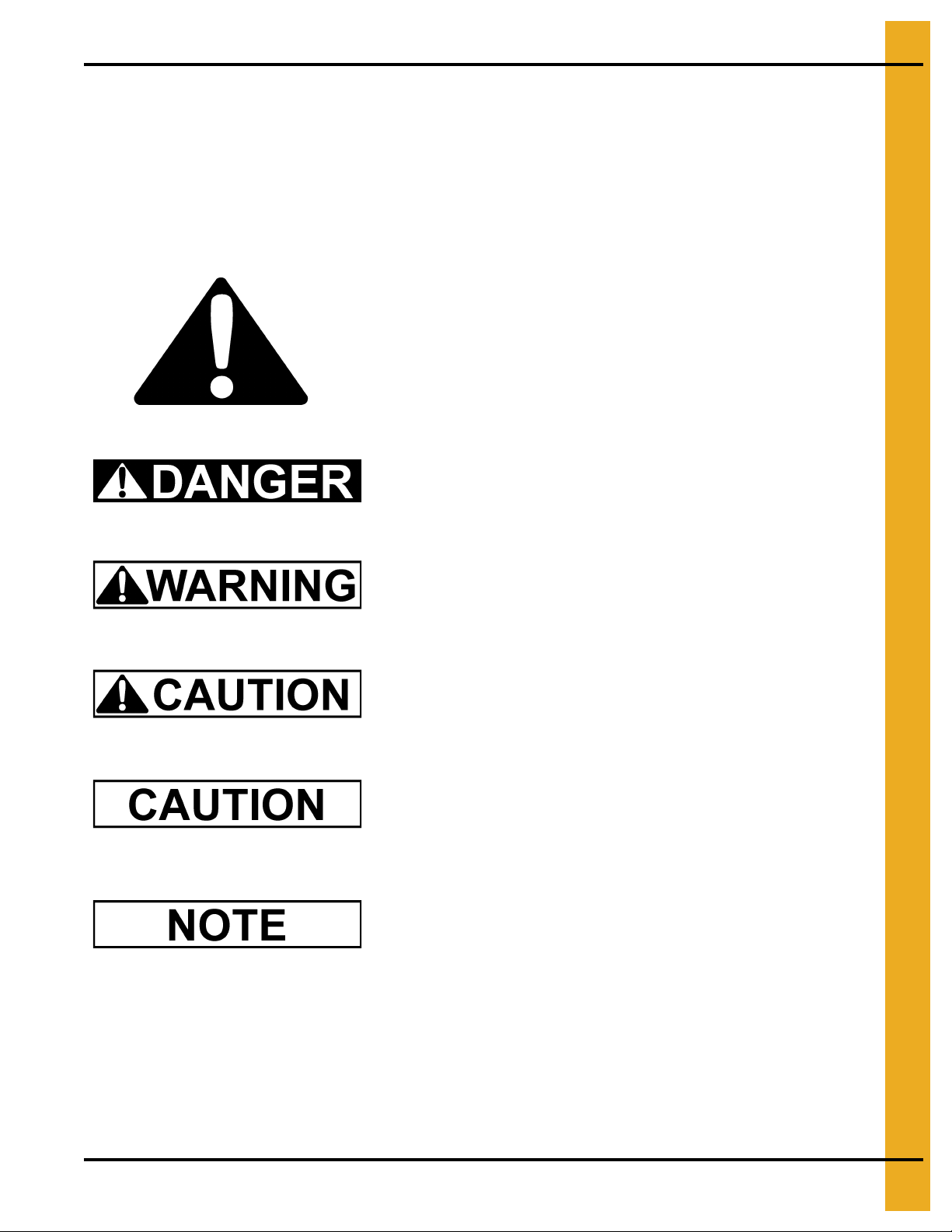
This is the safety alert symbol. It is used to alert you to
potential personal injury hazards. Obey all safety
messages that follow this symbol to avoid possible
injury or death.
WARNING indicates a potentially hazardous situation
which, if not avoided, could result in death or serious injury.
CAUTION indicates a potentially hazardous situation which,
if not avoided, may result in minor or moderate injury.
CAUTION used without the safety alert symbol indicates a
potentially hazardous situation which, if not avoided, may
result in property damage.
NOTE indicates information about the equipment that you
should pay special attention.
DANGER indicates an imminently hazardous situation
which, if not avoided, will result in death or serious injury.
Safety Guidelines
This manual contains information that is important for you, the owner/operator, to know and understand.
This information relates to protecting personal safety and preventing equipment problems. It is the
responsibility of the owner/operator to inform anyone operating or working in the area of this equipment
of these safety guidelines. To help you recognize this information, we use the symbols that are defined
below. Please read the manual and pay attention to these sections. Failure to read this manual and its
safety instructions is a misuse of the equipment and may lead to serious injury or death.
PNEG-195 4" Utility and Bulk Tank Auger 5
Page 6
2. Safety
Follow Safety Instructions
Carefully read all safety messages in this manual and
safety signs on your machine. Keep signs in good
condition. Replace missing or damaged safety signs. Be
sure new equipment components and repair parts include
the current safety signs. Replacement safety signs are
available from the manufacturer.
Learn how to operate the machine and how to use controls
properly. Do not let anyone operate without instruction.
Keep your machinery in proper working condition.
Unauthorized modifications to the machine may impair
the function and/or safety and affect machine life.
If you do not understand any part of this manual or need
assistance, contact your dealer.
Read and Understand Manual
Operate Motor Properly
To avoid serious injury or death, stay away from unit and make sure
everyone is clear of the equipment before starting or operating
the unit.
All electrical connections should be made in accordance with
the National Electric Code. Be sure equipment and bins are
properly grounded.
Do not operate electric motor equipped units until motors are
properly grounded.
Disconnect power on electrical driven units before resetting
motor overloads.
Do not repetitively stop and start the drive in order to free a plugged
condition. Jogging the drive in this manner can damage the
equipment and/or drive components.
Electric Shock Hazard
Safety Instructions
Our foremost concern is your safety and the safety of others associated with this equipment. We want to
keep you as a customer. This manual is to help you understand safe operating procedures and some
problems which may be encountered by the operator and other personnel.
As owner and/or operator, it is your responsibility to know what requirements, hazards and precautions
exist, and to inform all personnel associated with the equipment or in the area. Safety precautions may be
required from the personnel. Avoid any alterations to the equipment. Such alterations may p roduce a very
dangerous situation where SERIOUS INJURY or DEATH may occur.
This equipment shall be installed in accordance with the current installation codes and applicable
regulations which should be carefully followed in all cases. Authorities having jurisdiction should be
consulted before installations are made.
6 PNEG-195 4" Utility and Bulk Tank Auger
Page 7
2. Safety
Prepare for Emergencies
Be prepared if fire starts.
Keep a first aid kit and fire extinguisher handy.
Keep emergency numbers for doctors, ambulance service,
hospital and fire department near your telephone.
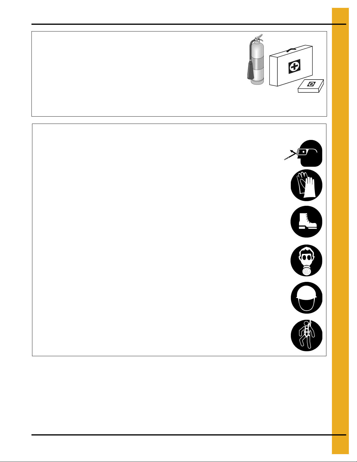
Keep Emergency Equipment
Quickly Accessible
Wear Protective Clothing
Wear close fitting clothing and safety equipment appropriate
to the job.
Remove all jewelry.
Long hair should be tied up and back.
Safety glasses should be worn at all times to protect eyes
from debris.
Wear gloves to protect your hands from sharp edges on
plastic or steel parts.
Wear steel toe boots to help protect your feet from falling
debris. Tuck in any loose or dangling shoe strings.
A respirator may be needed to prevent breathing potentially
toxic fumes and dust.
Wear hard hat to help protect your head.
Wear appropriate fall protection equipment when working at
elevations greater than six feet (6').
Eye Protection
Gloves
Steel Toe Boots
Respirator
Hard Hat
Fall Protection
PNEG-195 4" Utility and Bulk Tank Auger 7
Page 8

2. Safety
Operate Unload Equipment Properly
• Untrained operators subject themselves and others to SERIOUS INJURY
or DEATH. NEVER allow untrained personnel to operate this equipment.
• NEVER work alone.
• Keep children and other unqualified personnel out of the working
area at ALL times. Refer to the Start-Up section of this manual for
diagrams of the work area.
• Make sure ALL equipment is locked in position before operating.
• NEVER start equipment until ALL persons are clear of the work area.
• Keep hands and feet away from the auger intake and other moving parts.
• NEVER attempt to assist machinery operation or to remove trash from equipment while
in operation.
• Be sure all operators are adequately rested and prepared to perform all functions of operating
this equipment.
• NEVER allow any person intoxicated or under the influence of alcohol or drugs to operate
the equipment.
• Make sure someone is nearby who is aware of the proper shut down sequence in the event of an
accident or emergency.
• ALWAYS think before acting. NEVER act impulsively around the equipment.
• NEVER allow anyone inside a bin, truck or wagon which is being unloaded by an auger or
conveyor. Flowing grain can trap and suffocate in seconds.
• Use ample overhead lighting after sunset to light the work area.
• Keep area around intake free of obstacles such as electrical cords, blocks, etc., that might
trip workers.
• NEVER drive, stand or walk under the equipment.
• Use caution not to hit the auger when positioning the load.
• ALWAYS lock out ALL power to the equipment when finished unloading a bin.
• Be aware of pinch points. A pinch point is a narrow area between two surf aces that is likely to trap or
catch objects and so is a potential safety hazard.
Operate Unload
Equipment Safely
8 PNEG-195 4" Utility and Bulk Tank Auger
Page 9

2. Safety
Operator Qualifications
A. The User/Operator must be competent and experienced to operate auger equipment. Anyone who
works with or around augers must have good common sense in order to be qualified. T hese persons
must also know and meet all other qualifications, such as:
i. Any person who has not read and/or does not understand all operation and safety procedures
is not qualified to operate any auger systems.
ii. Certain regulations apply to personnel operating power machinery. Personnel under the age of
18 years may not operate power machinery, including augers. It is your responsibility, as owner
and/or supervisor, to know what these regulations are in your area or situation.
iii. Unqualified or incompetent persons are to remain out of the work area.
iv. O.S.H.A. (Occupational Safety and Health Administration) regulations state: “At the time of
initial assignment and at least annually thereafter, the employer shall instruct every employee
in the safe operation and servicing of all equipment with which the employee is, or will be
involved”. (Federal Occupational Safety and Health Standards for Agriculture. Subpart D,
Section 1928.57 (a) (6)).
B. As a requirement of O.S.H.A., it is necessary for the employer to train the employee in the safe
operating and safety procedures for this auger. The sign-off sheet is provided for your convenience
and personal record keeping. All unqualified persons are to stay out of the work area at all times. It
is strongly recommended that another qualified person who knows the shut down procedure is in the
area in the event of an emergency.
Date Employee Name Supervisor Name
PNEG-195 4" Utility and Bulk Tank Auger 9
Page 10

3. Safety Decals
Decal “A”
on Page 11
Decal “B”
on Page 11
Decal “C”
on Page 11
Decal “D”
on Page 11
Check components as specified below to ensure that the safety decals are in place and in good condition.
If a decal cannot be easily read for any reason or has be en painted over, replace it immediately. Contact
your dealer or the manufacturer to order a replacement decal free of charge.
GSI Decals
1004 E. Illinois St.
Assumption, IL. 62510
Phone: 1-217-226-4421
10 PNEG-195 4" Utility and Bulk Tank Auger
Page 11

DC-455
Keep clear of rotating auger and
moving parts.
Do not remove or modify guards.
Disconnect and lockout power
before servicing.
Failure to do so will result in
serious injury or death.
SHEAR POINT
Keep hands clear of moving
parts. Do not operate with
guard removed. Disconnect
and lock out power before
servicing.
DC-994
SHEAR POINT
Keep hands clear of moving
parts. Do not operate with
guard removed. Disconnect
and lock out power before
servicing.
DC-995
WARNINGWARNING
Decal “A”
“WARNING” Decal
Located on outside of front belt guard cover.
Size: 2-1/4" x 5"
Part #: DC-995
Decal “B”
“DANGER” Decal
Located on inside of back belt guard cover.
Size: 2-1/4" x 5"
Part #: DC-994
Decal “C”
“DANGER” Decal
Located on unloading tube near head plate.
Size: 4" x 9"
Part #: DC-834
Decal “D”
“DANGER” Decal
Located on unloading tube near intake guard.
Size: 4-1/4" x 5-7/16"
Part #: DC-455
DC-995
DC-994
DC-834
DC-455
3. Safety Decals
PNEG-195 4" Utility and Bulk Tank Auger 11
Page 12

3. Safety Decals
A. DANGER Sign No. DC-1395 was supplied with your bin unloading equipment. This safety sign
should be applied to the side of the bin near the bin openin g, so it will be viewed by people entering
into the bin storage building. Do not cover any safety signs or any other signs that are already there.
B. If the safety sign location suggested is not in full view because of equipment modifications, other
equipment in the area or any reason, then locate the safety sign in a more suitable location.
C. Be certain the surface is clean, dry and free of dirt and oil. Peel paper backing from decals and stick
into place. The adhesive backing will bond on contact.
NOTE: Please remember, safety signs provide important safety information for people working near bin
unloading equipment that is in operation.
NOTE: If the Safety Sign cannot be easily read for any reason or has been painted over, replace it
immediately. Additional Safety Signs may be obtained free of charge from your dealer, distributor
or ordered from the factory.
Order SAFETY SIGN NO. DC-1395
12 PNEG-195 4" Utility and Bulk Tank Auger
Page 13

4. Assembly
Assembly Instruction for GSI 4'' Utility and Bulk Tank Auger
See Figure on Page 20.
1.Bolt head bearing to head plate assembly using three (3) 5/16'' x 3/4'' carriage bolts with lock washers
and nuts. Bearing lock collar must be on front of bearing next to pulley.
2. Attach motor mount rods into head plate assembly with belt guard mounting angle under top nuts.
Note the position of the angle.
3. Slide head plate assembly over discharge end of auger housing. Bolt on head plate assembly using
four (4) 5/16" x 1-1/4" hex head bolts and nuts
4. Attach belt guard back cover to belt guard mounting angle using two (2) 5/16'' x 3/4'' bolts,
flat washers and lock nuts.
NOTE: Leave bolts loose until motor, pulley and belts are installed.
5. Slide flighting shaft through head bearing enough to install 8'' pulley on shaft with 5/16'' x 2'' roll pin.
NOTE: Roll pin side of pulley must be next to bearing lock collar. Locate head pulley in as close as
possible to head bearing. Tighten lock collar on bearing.
6. Position motor straps and motor clips on motor mounting rods and clamp together with four (4)
5/16" x 1" bolts and nuts. Install electric motor on motor mount and pulley on motor (motor and pulley
not furnished with unloading auger). Install A38 belts, tighten belts and lock in place with 5/8'' nuts.
7. Place support strap on auger housing directly behind head plate, clamp in place with half band using
two (2) 5/16" x 1-1/4" hex head bolts. Slide rod support strap over ends of 5/8'' motor mount rods and
attach to support strap with one 5/16'' x 3/4'' carriage bolt, flat washer, lock washer and nut.
8. Adjust belt guard back cover so that the belts and pulleys will clear the belt guard front cover when
it is installed. Tighten bolts securing the back cover to the mounting angle.
9. Attach belt guard front cover to belt guard back cover using six (6) #10 x 3/4'' self-drilling screws.
10. Bulk Tank Augers Only: Fasten full band to auger housing using a 5/16'' x 1-1/4'' hex hea d bolt and
nut. A cable can be used to support the bulk tank auger.
11. If unit has trouble starting under load, cut down on amount of exposed flight on auger intake.
NOTE: Slide extension flighting assembly into extension housing assembly. Bolt flighting assemblies
together so that the ends of the flighting are approximately a half turn apart using 5/16'' x 1-1/2''
hex head bolts and lock nuts. Connect auger housing together with connecting band. Be sure
auger housings are tight together. Use bolts already in connecting band. The connecting band
should be half on each housing assembly.
PNEG-195 4" Utility and Bulk Tank Auger 13
Page 14

4. Assembly
Bearing and Washer Detail
Figure 4A
Install supplied stub shaft inside auger flight with 1/4" x 1-1/2" bolt and a 1/4" lock nu t. Position flight with
stub shaft and washer into unloader bearing. (See Figure 4A.)
4" Unloaders require 17" of exposed flight. It is necessary to field cut auger tube lengths to accommo date
required exposure. Butt the auger tube to the unloader tube and attach using a connecting band.
IMPORTANT: Auger stub shaft supplied is designed to fit GSI 4" bulk tank augers. If using a
different auger supplier it may be necessary to modify or fabricate a stub shaft for
the unloader bearing.
14 PNEG-195 4" Utility and Bulk Tank Auger
Page 15

5. Electric Motor Drives
Disconnect power before resetting motor overloads. Make certain electric motors
are grounded.
Suggested horsepower is listed in below Chart. 1750 RPM electric motors and controls sha ll be in stalled
by a qualified electrician and must meet the standards set by the National Electrical Code and all local and
state codes. Reset and motor starting controls shall be loca ted where the operator has unrestricted access
to the controls.
Magnetic starter should be used for the protection and the motors. This is to assure the operator of
accidental restart caused by power interruption, conduc tor fault, low voltage, circuit interruption or thermal
overload protection, make sure this type motor has a manual reset.
Horsepower Information for Electric Motor Drive
This chart is a suggested horsepower requirement for standard 4" Utility Augers.
Length Motor HP
11' 1/2
15' 1/2
20' 3/4
Horsepower recommendations are for augering reasonably dry grain at different angles. Grain with 15%
moisture and above may require more horsepower if maximum capacity is to be maintained. Use a
2-1/2'' to 3'' motor pulley for a recommended auger speed of 550 RPM to 650 RPM. Motor pulley not
furnished. Excessive wear will result if auger speed is in excess of 700 RPM and auger load up will occur
if auger speed is less than 500 RPM or flow gate is required.
Auger speeds in excess of 750 RPM should be avoided as excessive wear will result. Auger speed below
450 RPM require a flow control to restrict intake to the auger. High torque is required to turn the flighting
if it is permitted to “load up” at low speed and damage to the auger can result. An option al control gate is
available for this purpose.
PNEG-195 4" Utility and Bulk Tank Auger 15
Page 16

6. Start-Up
The operator should be aware of any unusual vibration or noises during the initial
start-up and break-in period. All safety shields and guards are to remain in place.
Keep hands, feet and clothing away from rotating and moving parts.
Start-Up and Break-In Information
Before adding power it is essential to inspect the drive unit and know how and where to shut down t he unit
in case of an emergency. Have one person in a position to where they can monitor the operation of the
equipment during operation.
Any auger should go through a “break-in” period, whether new or being idle of a season. The “break-in”
period is to polish the auger and tube to make surfaces smooth. The auger should be run at partial capacity
until several hundred bushels of grain have been augered through. After the auger and tube are polished
it can be run at full capacity.
Never operate the auger empty for any length of time, for excessive wear will result. If at all possible, do
not stop or start the auger while loaded, especially before the auger and tube are well polished, this may
cause auger to “bind-up”.
For efficient operation of the equipment, auger speed is very important.
1. Extreme wear result if auger speed is in excess of what is recommended.
2. Auger will load up or overload if auger speed is too slow. Overload of the auger will cause motor to
overload and higher torque will be required to turn auger, which in turn may cause damage to
the auger.
16 PNEG-195 4" Utility and Bulk Tank Auger
Page 17

7. Operation
Before operating augers be sure all personnel are clear.
Observe work area restrictions. Make certain everyone is clear before operating
the machine.
Utility Augers Only
Utility augers are primarily designed as portable units. These augers are not designed for permanent
installations. A utility auger has many different uses. Since it is not sold with an undercarriage or other
method of support, it must be supported by the user satisfactorily for the specific job. Always be sure to
fasten the discharge and intake end in place so the auger will stay in place throughout operation.
Bulk Tank Augers
Bulk tank augers are primarily designed for use in bulk tank unloading augers only. These units are not
furnished with intake guards. THEY ARE TO BE USED ONLY IN A BULK TANK. If removed with the
intention of using as a utility auger, an intake guard is required, order from parts page, and install prior
to use.
Since it is not sold with an undercarriage or other method of support, it must be supported by the user
satisfactorily for the specific job. Always be sure to fasten the discharge and intake end in place so the
auger will stay in place throughout operation.
Full Load Operating Procedures
It is good practice to visually inspect the auger periodically during the actual operation. You should be alert
for unusual vibrations, noises and the loosening of any fasteners.
PNEG-195 4" Utility and Bulk Tank Auger 17
Page 18

8. Shut Down
Stop motor and lock out power source when servicing and/or adjusting
the equipment.
Precaution should be made to prevent anyone from entering work area.
Normal Shut Down
Before stopping the unit, make certain that hopper and inclined tube are empty. Never leave the work area
without locking out the power supply.
Emergency Shut Down
If the auger has to be shut down while in full operation, disconnect and lock out th e powe r source. Never
attempt to restart when auger tube is full.
NOTE: Damage may occur to the auger if attempting to start the auger while unit is under load.
This type damage is considered abuse to the equipment. Re-connect power source and clear
auger gradually.
Lock Out
Augers must be stopped and power source turned OFF when operator is:
1. Away from work area.
2. Servicing or adjusting equipment.
Storage Preparation
1. Check all guards and shields making sure they are in place, secured and functional.
2. Replace any safety signs or warning decals that are warn, missing or illegible. These items are listed
on Page 11 and may be obtained from GSI Group dealer or from the factory.
3. Check to ensure all fasteners are tight.
18 PNEG-195 4" Utility and Bulk Tank Auger
Page 19

NOTES
PNEG-195 4" Utility and Bulk Tank Auger 19
Page 20

9. Parts List
4'' Bulk Tank Auger Components
20 PNEG-195 4" Utility and Bulk Tank Auger
Page 21

4'' Bulk Tank Auger Components Parts list
Ref # Part # Description Qty
G60618 4'' Bulk Tank Utility Auger Boxed Parts 1
1 RA-3144 4" x 114" Feed Auger Housing 1
1 RA-3145 4" x 162" Feed Auger Housing 1
1 RA-3146 4" x 222" Feed Auger Housing 1
2 G6977A1-A 4" x 134-1/2" Auger Flight Weld 11' Utility 1
2 G6977A1-B 4" x 182-1/2" Auger Flight Weld 15' Utility 1
2 G6977A1-C 4" x 242-1/2" Auger Flight Weld 20' Utility 1
3 GK2843 Rod, Motor Mount 5/8" Plated 2
4 GK2841 4'' Top Motor Mount Strap 2
5 GK2842 4'' Bottom Motor Mount Clip 2
6 GK3500 4" Head Plate Weldment 1
9. Parts List
7 G5012A1 4" Rod Support 1
8 GK1583 Flangette Bearing 1'' 1
9 G6049A1 4" Support Strap Weldment 1
10 GK3498 8'' 1 Groove Pulley (1'' Bore) 1
11 G40105 A38 Belt 1
12 GK2155 Half Band 4" x 2" 12 Gauge Galvanized 1
13 S-4377 5/16'' x 2'' Long Grooved Roll Pin 1
14 GC00155 Belt Guard Mo un ti n g Angl e 1
15 FLX-2987 Belt Guard Back Cover 1
16 FLX-2986 Belt Guard Front Cover 1
17 S-4110 Hex Nut 5/8"-11 ZN Grade 5 4
18 GK3826 4" Connecting Band (Bulk Tank Auger Only) 1
19 GC00005 4" Clamp Band (Bulk Tank Auger Only) 1
PNEG-195 4" Utility and Bulk Tank Auger 21
Page 22

10. Troubleshooting
Problem Possible Cause Solution
Utility auger
Low capacity
Auger plugs
1. Drive belt may be overtightened, putting
head stub and flight in a bind. Damage
can occur to the auger flighting, thus
caused noise. Damage usually caused
from foreign material having been run
through the auger.
1. The auger may not be getting
enough grain.
2. The auger is moving too slowly.
1. The auger may be getting too much
grain, causing “jamming” inside
the housing.
2. The motor may be too small or
wired improperly.
3. The grain may be wet.
4. The auger may be jammed with
foreign material.
1. It may be necessary to remove the flighting
for inspection.
2. Adjust the drive belt to the proper tension.
1. Check that the intake has not bridged over,
restricting flow. The exposed flighting at the
auger intake should be covered with grain to
achieve maximum capacity.
2. Check the auger speed. Speeds slower than
the recommended speed will result in
low capacity.
1. Decrease the amount of grain the auger
is gathering.
2. If the motor is a newer light weight
aluminum type, the next larger size should
be considered.
3. If wet grain or other hard-to-move material is
being augured, use a larger size motor than
recommended for normal use.
4. Be sure there is no foreign material in the
auger such as sacks, tarp corners, etc.
5. The discharge end may be plugged.
5. Make sure the discharge end of the auger is
not plugged. A plug of the discharge end will
cause an auger plug.
22 PNEG-195 4" Utility and Bulk Tank Auger
Page 23

11. Warranty
9101239_1_CR_rev7.DOC (revised July 2009)
GSI Group, LLC Limited Warranty
The GSI Group, LLC (“GSI”) warrants products which it manufactures to be free of defects in materials and workmanship
under normal usage and conditions for a period of 12 months after sale to the original end-user or if a foreign sale,
14 months from arrival at port of discharge, whichever is earlier. The end-user’s sole remedy (and GSI’s only obligation)
is to repair or replace, at GSI’s option and expense, products that in GSI’s judgment, contain a material defect in materials
or workmanship. Expenses incurred by or on behalf of the end-user without prior written authorization from the GSI
Warranty Group shall be the sole responsibility of the end-user.
Warranty Extensions:
The Limited Warranty period is extended for the following products:
Product Warranty Period
Performer Series Direct Drive Fan Motor 3 Years
AP Fans and Flooring
Cumberland
Feeding/Watering
Systems
Grain Systems Grain Bin Structural Design 5 Years
Grain Systems
Farm Fans
Zimmerman
All Fiberglass Housings Lifetime
All Fiberglass Propellers Lifetime
Feeder System Pan Assemblies 5 Years **
Feed Tubes (1-3/4" and 2.00") 10 Years *
Centerless Augers 10 Years *
Watering Nipples 10 Years *
Portable and Tower Dryers 2 Years
Portable and Tower Dryer Frames and
Internal Infrastructure †
5 Years
* Warranty prorated from list price:
0 to 3 years - no cost to end-user
3 to 5 years - end-user pays 25%
5 to 7 years - end-user pays 50%
7 to 10 years - end-user pays 75%
** Warranty prorated from list price:
0 to 3 years - no cost to end-user
3 to 5 years - end-user pays 50%
† Motors, burner components
and moving parts not included.
Portable dryer screens included.
Tower dryer screens not included.
GSI further warrants that the portable and tower dryer frame and basket, excluding all auger and auger drive components,
shall be free from defects in materials for a period of time beginning on the twelfth (12
and continuing until the sixtieth (60
th
) month from the date of purchase (extended warranty period). During the extended
th
) month from the date of purchase
warranty period, GSI will replace the frame or basket components that prove to be defective under normal conditions of
use without charge, excluding the labor, transportation, and/or shipping costs incurred in the performance of this
extended warranty.
Conditions and Limitations:
THERE ARE NO WARRANTIES THAT EXTEND BEYOND THE LIMITED WARRANTY DESCRIPTION SET FORTH
ABOVE. SPECIFICALLY, GSI MAKES NO FURTHER WARRANTY OF ANY KIND, EXPRESS OR IMPLIED,
INCLUDING, WITHOUT LIMITATION, WARRANTIES OF MERCHANTABILITY OR FITNESS FOR A PARTICULAR
PURPOSE OR USE IN CONNECTION WITH: (I) PRODUCT MANUFACTURED OR SOLD BY GSI OR (II) ANY ADVICE,
INSTRUCTION, RECOMMENDATION OR SUGGESTION PROVIDED BY AN AGENT, REPRESENTA TIVE OR
EMPLOYEE OF GSI REGARDING OR RELATED TO THE CONFIGURATION, INSTALLATION, LAYOUT, SUITABILITY
FOR A PARTICULAR PURPOSE, OR DESIGN OF SUCH PRODUCTS.
GSI shall not be liable for any direct, indirect, incidental or consequential damages, including, without limitation, loss of
anticipated profits or benefits. The sole and exclusive remedy is set forth in the Limited Warranty, which shall not exceed
the amount paid for the product purchased. This warranty is not transferable and applies only to the original end-user. GSI
shall have no obligation or responsibility for any representations or warranties made by or on behalf of any dealer, agent
or distributor.
GSI assumes no responsibility for claims resulting from construction defects or unauthorized modifications to products
which it manufactured. Modifications to products not specifically delineated in the manual accompanying the equipment at
initial sale will void the Limited Warranty.
This Limited Warranty shall not extend to products or parts which have been damaged by negligent use, misuse, alteration,
accident or which have been improperly/inadequately maintained. This Limited Warranty extends solely to products
manufactured by GSI.
Prior to installation, the end-user has the responsibility to comply with federal, state and local codes which apply to the
location and installation of products manufactured or sold by GSI.
PNEG-195 4" Utility and Bulk Tank Auger 23
Page 24

This equipment shall be installed in accordance with
the current installation codes and applicable
regulations which should be carefully followed in all
cases. Authorities having jurisdiction should be
consulted before installations are made.
Copyright © 2010 by GSI Group
Printed in the USA
GSI Group
1004 E. Illinois St.
Assumption, IL 62510-0020
Phone: 1-217-226-4421
Fax: 1-217-226-4420
www.gsiag.com
 Loading...