

Page 1

Top Dry Stairs Assembly
Models:
24 FT — 36 FT DIAMETER
Constuction Manual
PNEG-1936
Date: 06-10-13
PNEG-1936
Page 2

All information, illustrations, photos, and specifications in this manual are based on the latest
information available at the time of publication. The right is reserved to make changes at any
time without notice.
2 PNEG-1936 Top Dryer
Page 3

Table of Contents
Contents
Chapter 1 Safety Precautions ....................................................................................................................5
Safety Guidelines ........................................................................................................................5
Cautionary Symbols ....................................................................................................................7
Safety Decals..............................................................................................................................8
Safety Sign-off Sheet ................................................................................................................. 11
Chapter 2 Top Platform Assembly ........................................................................................................... 13
Top Platform Assembly — Overview ...........................................................................................15
Assembly of Sidewall Attachment Bracket and Knee Brace...........................................................16
Assembly of Inside Platform Rail, Platform Plank, Inside Stair Rail and Horizontal Support
Brace ...........................................................................................................................18
Assembly of Platform End Plank and Platform Planks...................................................................22
Assembly of Platform End Handrail Support, Outside Platform Rail and Platform corner Handrail
Anchors........................................................................................................................ 24
Assembly of Outside Stair Rail, Handrail Support Attachment brackets and Handrail Pivot
Brackets ....................................................................................................................... 26
Assembly of Platform Handrails .................................................................................................. 28
Chapter 3 Stairs Assembly-1 ...................................................................................................................31
Stairs Assembly 1 — Overview...................................................................................................33
Assembly of Platform support step and standard stair step............................................................ 34
Assembly of Inside Stair Rail, Sidewall Attachment Bracket and Horizontal Support Brace .............. 36
Assembly of Outside Stair Rail and Handrail Support Attachment Bracket ......................................38
Assembly of Handrail Support, Handrail Pivot Brackets and Standard Stair Steps...........................40
Chapter 4 Intermediate Platform Assembly..............................................................................................43
Intermediate Platform Assembly — Overview .............................................................................. 45
Assembly of Sidewall Attachment Brackets and Knee Braces .......................................................46
Assembly of Inside Platform Rail, Inside Stair Rail and Horizontal Support Brace............................48
Assembly of Platform Planks to Inside Platform Rail and Knee Brace.............................................50
Assembly of Platform Planks ......................................................................................................52
Assembly of Outside Platform Rail and Handrail support Bracket................................................... 54
Assembly of Bottom Handrail Support, Handrail Pivot Brackets and Platform handrail
support......................................................................................................................... 56
Assembly of Outside stair rail, Handrail Support Attachment Brackets, Handrail Pivot Brackets and
Platform handrail supports..............................................................................................58
Assembly of Stair Handrails........................................................................................................ 61
Assembly of Platform Handrails .................................................................................................. 63
Chapter 5 Stairs Assembly-2 ...................................................................................................................65
Stairs Assembly 2 — Overview...................................................................................................67
Assembly of Platform support step and standard stair steps ..........................................................68
Assembly of Inside Stair Rail, Sidewall Attachment Bracket and Horizontal Support Brace .............. 70
Assembly of Outside Stair Rail and Handrail Support Attachment Bracket ......................................72
Assembly of Handrail Support and Handrail Pivot Brackets ........................................................... 74
Assembly of Platform Handrails and Stair Handrails ..................................................................... 76
Chapter 6 Stairs Assembly-3 ...................................................................................................................79
Stairs Assembly 3 — Overview...................................................................................................81
Assembly of Inside Stair Rail, Sidewall Attachment Bracket and Horizontal Support Brace .............. 82
Assembly of Outside Stair Rail and Handrail Support Attachment Bracket ......................................84
Assembly of Handrail Support, Handrail Pivot Brackets and Standard Stair Steps...........................86
Assembly of Stair Handrails........................................................................................................ 88
GSI Group, LLC Limited Warranty............................................................................................91
PNEG-1936 Top Dryer 3
Page 4

NOTES
4 PNEG-1936 Top Dryer
Page 5

1 Safety Precautions
Topics Covered in this Chapter
▪ Safety Guidelines
▪ Cautionary Symbols
▪ Safety Decals
▪ Safety Sign-off Sheet
Safety Guidelines
Safety guidelines are general-to-specific safety rules that must be respected at all times in the grain storage environment.
Our foremost concern is your safety and the safety of others associated with grain handling equipment.
This manual is to help you understand safe operating procedures and some problems that can be encountered by the operator and other personnel.
As owner and/or operator, you are responsible to know what requirements, hazards, and precautions exist
and inform all personnel associated with the equipment or in the area. Avoid any alterations to the equipment. It can produce a very dangerous situation, where SERIOUS INJURY or DEATH can occur.
This equipment shall be installed in accordance with the current installation codes and applicable regulations, which should be carefully followed in all cases. Authorities having jurisdiction must be consulted
before installations are made.
You should consider the location of the bin site relative to power line locations or electrical transmission
equipment. Contact your local power company to review your installation plan or for information concerning
required equipment clearance. Clearance of portable equipment that can be taken to the bin site must also
be reviewed and considered. Any electrical control equipment in contact with the bin must be properly
grounded and installed in accordance with National Electric Code provisions and all local codes.
This product is intended for the use of grain storage only. Any other use is a misuse of the product.
This product has sharp edges, which may cause serious injury. To avoid injury,
CAUTION
Sidewall bundles or sheets must be stored in a safe manner. The safest method of storing sidewall bundles
is laying horizontally with the arch of the sheet upward, like a dome. Sidewall sheets stored on edge must
be secured so that they cannot fall over and cause injury. Use care when handling and moving sidewall
bundles.
Personnel operating or working around equipment must read this manual. This manual must be delivered
with equipment to its owner. Failure to read this manual and its safety instructions is a misuse of the
equipment.
handle sharp edges with caution and always use proper protective clothing and
equipment.
PNEG-1936 Top Dryer
5
Page 6
Chapter 1: Safety Precautions
Follow Safety Instructions — Read and Understand Manual
• Carefully read all safety messages in this manual and safety
signs on your machine. Keep signs in good condition.
Replace missing or damaged safety signs. Be sure new
equipment components and repair parts include the current
safety signs. Replacement safety signs are available from
the manufacturer.
• Learn how to operate the machine and how to use controls
properly. Do not let anyone operate without instruction.
• Keep your machinery in proper working condition. Unauthorized modifications to the machine can impair the function
and/or safety and affect machine life.
• If you do not understand any part of this manual or need
assistance, contact your dealer.
Practice Safe Maintenance — Maintain Equipment and Work
Area
• Understand service procedures before doing work. Keep
area clean and dry.
• Never lubricate, service, or adjust machine while it is in operation. Keep hands, feet, and clothing away from rotating
parts.
• Keep all parts in good condition and properly installed. Fix
damage immediately. Replace worn or broken parts. Remove
any built-up grease, oil, and debris.
Prepare for Emergencies — Keep Emergency Equipment
Accessible
• Be prepared if fire starts.
• Keep a first aid kit and fire extinguisher handy.
• Keep emergency numbers for doctors, ambulance service,
hospital, and fire department near your telephone.
Wear Protective Clothing
• Wear close-fitting clothing and safety equipment appropriate to the job.
• Remove all jewelry
• Tie long hair up and back.
• Wear safety glasses at all times to protect eyes from
debris.
6 PNEG-1936 Top Dryer
Eye Protection
Page 7
Chapter 1: Safety Precautions
• Wear gloves to protect your hands from sharp edges on
plastic or steel parts.
• Wear steel-toed boots to help protect your feet from falling
debris. Tuck in any loose or dangling shoestrings.
• A respirator may be needed to prevent breathing potentially toxic fumes and dust.
• Wear a hard hat to help protect your head.
• Wear appropriate fall protection equipment when working
at elevations greater than 6 ft (1.8 m).
Gloves
Steel-Toed Boots
Respirator
Hard Hat
Fall Protection
Cautionary Symbols
Cautionary symbols appear in the various decals of your product, and alerts the user of potential or imminent risk of danger.
This manual contains information that is important for you, the owner/operator, to know and understand.
This information relates to protecting personal safety and preventing equipment problems.
It is the responsibility of the owner/operator to inform anyone operating or working in the area of this equipment of these safety guidelines. To help you recognize this information, we use the symbols that are
defined below. Please read the manual and pay attention to these sections. Failure to read this manual
and its safety instructions is a misuse of the equipment and may lead to serious injury or death.
Make sure to familiarize yourself with these symbols prior to installing, operating, or
DANGER
Table 1-1 Description of the different cautionary symbols
servicing your grain equipment. Failure to do so may lead to serious injury or death.
Symbol Description
This symbol indicates an imminently hazardous situation which, if
not avoided, will result in serious injury or death.
This symbol indicates a potentially hazardous situation which, if not
avoided, may result in serious injury or death.
PNEG-1936 Top Dryer
7
Page 8

Chapter 1: Safety Precautions
Table 1-1 Description of the different cautionary symbols (cont'd.)
Symbol Description
This symbol indicates a potentially hazardous situation which, if not
avoided, may result in minor or moderate injury.
This symbol indicates a potentially hazardous situation which, if not
avoided, may result in property damage.
Safety Decals
The safety decals on your grain equipment are safety indicators which must be carefully read and understood by all personnel involved in the installation, operation, service, and maintenance of the grain
equipment.
The manufacturer does not warrant any roof damage caused by excessive vacuum or internal pressure
from fans or other air moving systems. Adequate ventilation and/or “makeup air” devices should be provided for all powered air handling systems. The manufacturer does not recommend the use of downward
flow systems (suction). Severe roof damage can result from any blockage of air passages. Running fans
during high humidity and cold weather conditions can cause air exhaust or intake ports to freeze.
8 PNEG-1936 Top Dryer
Page 9

Chapter 1: Safety Precautions
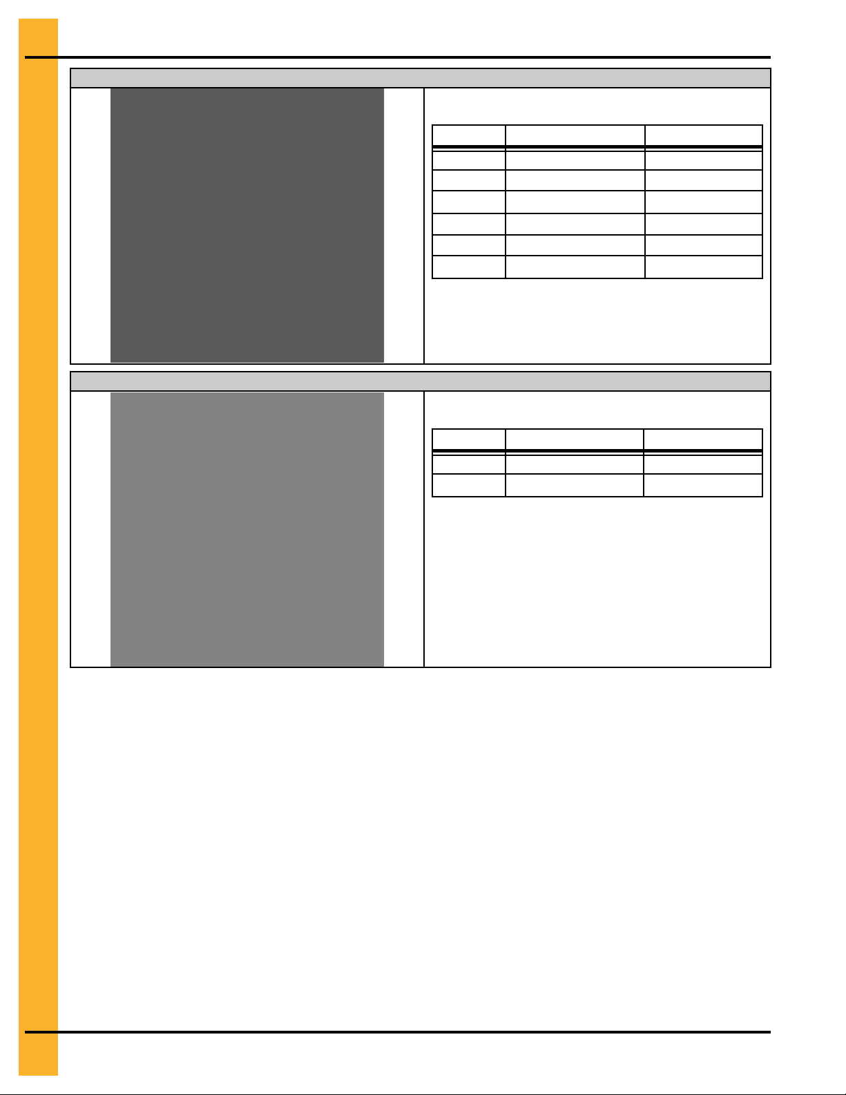
ATTENTION: Decal shown below must be present on the outside of the door cover of the two ring, 24 in.
(61 cm) porthole door cover and the roof manway cover. If a decal has been damaged or is missing in any
of these locations, contact the manufacturer for a free replacement decal.
GSI Decals
1004 E. Illinois Street
Assumption, IL 62510
Phone: 1–217–226–4421
PNEG-1936 Top Dryer 9
Page 10

Chapter 1: Safety Precautions
ATTENTION: Decal shown below must be present on the outside of the door cover of the two ring, 24 in.
(61 cm) porthole door cover and the roof manway cover. If a decal has been damaged or is missing in any
of these locations, contact the manufacturer for a free replacement decal.
GSI Decals
1004 E. Illinois Street
Assumption, IL 62510
Phone: 1–217–226–4421
10 PNEG-1936 Top Dryer
Page 11

Chapter 1: Safety Precautions
Safety Sign-off Sheet
Sign-off sheet verifying that all personnel have read and understood the safety instructions.
As a requirement of O.S.H.A., it is necessary for the employer to train the employee in the safe operating
and safety procedures for this equipment. This sign-off sheet is provided for your convenience and personal record keeping. All unqualified persons must stay out of the work area at all times. It is strongly recommended that another qualified person who knows the shutoff procedure be in the area in the event of
an emergency.
Date Employee Name
Supervisor Name
PNEG-1936 Top Dryer 11
Page 12

NOTES
12 PNEG-1936 Top Dryer
Page 13

2 Top Platform Assembly
Topics Covered in this Chapter
▪ Top Platform Assembly — Overview
▪ Assembly of Sidewall Attachment Bracket and Knee Brace
▪ Assembly of Inside Platform Rail, Platform Plank, Inside Stair Rail and Horizontal Support
Brace
▪ Assembly of Platform End Plank and Platform Planks
▪ Assembly of Platform End Handrail Support, Outside Platform Rail and Platform corner Hand-
rail Anchors
▪ Assembly of Outside Stair Rail, Handrail Support Attachment brackets and Handrail Pivot
Brackets
▪ Assembly of Platform Handrails
PNEG-1936 Top Dryer 13
Page 14

Chapter 2: Top Platform Assembly
14 PNEG-1936 Top Dryer
Page 15

Top Platform Assembly — Overview
Chapter 2: Top Platform Assembly
PNEG-1936 Top Dryer 15
Page 16

Chapter 2: Top Platform Assembly
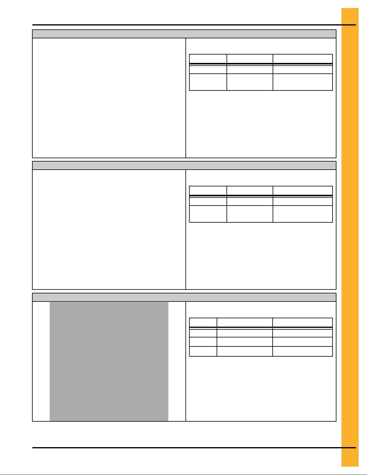
Assembly of Sidewall Attachment Bracket and Knee Brace
Figure 2-1 Assembly of Sidewall attachment brackets and knee braces
Assembly of sidewall attachment brackets and knee braces to stiffeners
Assembly of sidewall attachment bracket and knee brace to sidewall sheet
Assembly of sidewall attachment bracket and knee brace to stiffener
Table 2-1 Parts list
Part Number
STR-1162 Sidewall attachment bracket 3
STR-1165
S-7927
S-968
16 PNEG-1936 Top Dryer
Knee brace
3/8 x 1 in. flange bolt
3/8 in. flange nut
Description Quantity
3
20
20
Page 17

Chapter 2: Top Platform Assembly
Assembly of sidewall attachment brackets and knee braces to stiffeners
Table 2-2 Assembly Sequence
Callout Part number
B STR-1162 2
A , C S-7927 , S-968 6 , 6
D STR-1165 2
A , C S-7927 , S-968 4 , 4
NOTE: Start the assembly with the stiffener on the
sidewall sheet below the manway hole location on the roof.
Assembly of sidewall attachment bracket and knee brace to sidewall sheet
Table 2-3 Assembly Sequence
Callout Part number
B STR-1162 1
A , C S-7927 , S-968 3 , 3
D STR-1165 1
A , C S-7927 , S-968 2 , 2
Quantity
Quantity
IMPORTANT: B and D should be centered and aligned
Assembly of sidewall attachment bracket and knee brace to stiffener
Table 2-4 Assembly Sequence
Callout Part number
B STR-1162 1
A , C S-7927 , S-968 3 , 3
D STR-1165 1
A , C S-7927 , S-968 2 , 2
NOTE: Align B to the stiffener holes (10,11 and 12)
from the top of the sidewall sheet.
exactly between the two sidewall stiffeners. Field drill the holes in the sidewall sheet to attach B and D.
Quantity
PNEG-1936 Top Dryer 17
Page 18
Chapter 2: Top Platform Assembly
Assembly of Inside Platform Rail, Platform Plank, Inside Stair Rail and Horizontal Support Brace
Figure 2-2 Assembly of Inside Platform Rail, Platform Plank, Inside Stair Rail and Horizontal Support Brace
Assembly of Inside platform rail to sidewall attachment brackets
Assembly of platform plank to inside platform rail and knee brace
Assembly of platform plank to inside platform rail and knee brace
Assembly of Inside stair rail to Inside platform rail and horizontal support brace to the inside stair rail
Assembly of Inside stair rail to sidewall attachment bracket
Table 2-5 Parts list
Part Number
STR-1171
STR-1173
STR-1163 Inside stair rail
STR-1164
S-7927
S-968
Inside platform rail
Platform plank
Horizontal support brace
3/8 x 1 in. flange bolt
3/8 in. flange nut
Description Quantity
1
2
1
1
18
18
18 PNEG-1936 Top Dryer
Page 19
Assembly of Inside platform rail to sidewall attachment brackets
Table 2-6 Assembly Sequence
Chapter 2: Top Platform Assembly
Callout Part number
E STR-1171 1
A , C S-7927 , S-968 4 , 4
NOTE: Do not tighten the inside platform rail. It should
be tightened only after the platform planks are
attached.
Assembly of platform plank to inside platform rail and knee brace
Table 2-7 Assembly Sequence
Callout Part number
E STR-1171
H STR-1173 1
A , C S-7927 , S-968 4 , 4
Quantity
Quantity
—
NOTE: Make sure the bolts and nuts are oriented
properly.
Assembly of platform plank to inside platform rail and knee brace
Table 2-8 Assembly Sequence
Callout Part number
H STR-1173 1
A , C S-7927 , S-968 4 , 4
NOTE: Make sure the bolts and nuts are oriented
properly.
Quantity
PNEG-1936 Top Dryer 19
Page 20
Chapter 2: Top Platform Assembly
Assembly of inside stair rail to inside platform rail and horizontal support brace to the inside stair rail
Table 2-9 Assembly Sequence
Callout Part number
NOTE: Make sure the bolts and nuts are oriented
Assembly of inside stair rail to sidewall attachment bracket
Table 2-10 Assembly Sequence
Callout Part number
NOTE: Make sure the bolts and nuts are oriented
Quantity
E STR-1171
F STR-1163 1
A , C S-7927, S-968 1 , 1
G STR-1164 1
D STR-1165 1
A , C S-7927 , S-968 4 , 4
properly.
F STR-1163
A , C S-7927 , S-968 1 , 1
properly.
—
Quantity
—
20 PNEG-1936 Top Dryer
Page 21

Chapter 2: Top Platform Assembly
PNEG-1936 Top Dryer 21
Page 22
Chapter 2: Top Platform Assembly
Assembly of Platform End Plank and Platform Planks
Figure 2-3 Assembly of Platform End Plank and Platform Planks
Assembly of platform end plank
Assembly of platform planks
Assembly of platform planks
Table 2-11 Parts list
Part Number
STR-1173
STR-1174
S-7927
S-968
S-4303 5/16 x 3/4 in. truss bolt 15
S-3611
Platform plank
Platform end plank
3/8 x 1 in. flange bolt
3/8 in. flange nut
5/16 in. flange nut
Description Quantity
4
1
10
10
15
22 PNEG-1936 Top Dryer
Page 23

Assembly of platform end plank
Chapter 2: Top Platform Assembly
Table 2-12 Assembly Sequence
Assembly of platform planks
Callout Part number
I STR-1174 1
A , C S-7927 , S-968 2 , 2
J , K S-4303 , S-3611 3 , 3
NOTE: I should be seated on top of H and bolted with
J and K. Make sure the bolts and nuts are ori-
ented properly.
Table 2-13 Assembly Sequence
Callout Part number
H STR-1173 2
A , C S-7927 , S-968 4 , 4
J , K S-4303 , S-3611 6 , 6
Quantity
Quantity
Assembly of platform planks
NOTE: Each H should be adjusted and seated on top
of the adjacent H. Make sure the bolts and
nuts are oriented properly.
Table 2-14 Assembly Sequence
Callout Part number
H STR-1173 2
A , C S-7927 , S-968 4 , 4
J , K S-4303 , S-3611 6 , 6
NOTE: Each H should be adjusted and seated on top
of the adjacent H. Make sure the bolts and
nuts are oriented properly.
Quantity
PNEG-1936 Top Dryer 23
Page 24
Chapter 2: Top Platform Assembly
Assembly of Platform End Handrail Support, Outside Platform Rail and Platform corner Handrail Anchors
Figure 2-4 Assembly of Platform End Handrail Support and Outside Platform Rail
Assembly of platform end handrail supports to platform rail and end plank
Assembly of outside platform rail to the platform planks
Assembly of platform corner handrail anchors to platform end rail supports
Table 2-15 Parts list
Part Number
STR-1176
STR-1172
STR-1177 Platform corner handrail anchor 4
S-7927
S-968
S-7645
S-3611
24 PNEG-1936 Top Dryer
Platform end handrail support
Outside platform rail
3/8 x 1 in. flange bolt
3/8 in. flange nut
5/16 x 3/4 in. carriage bolt
5/16 in. flange nut
Description Quantity
2
1
18
18
8
8
Page 25
Chapter 2: Top Platform Assembly
Assembly of platform end handrail supports to platform rail and end plank
Table 2-16 Assembly Sequence
Assembly of outside platform rail to the platform planks
Callout Part number
L STR-1176 2
A , C
NOTE: Make sure the bolts and nuts are oriented
properly.
Table 2-17 Assembly Sequence
Callout Part number
M STR-1172 1
A , C
S-7927 , S-
968
S-7927 , S-
968
Quantity
4 , 4
Quantity
14 , 14
NOTE: Make sure the bolts and nuts are oriented
properly.
Assembly of platform corner handrail anchors to platform end rail supports
Table 2-18 Assembly Sequence
Callout Part number
L STR-1176
N STR-1177 4
O , K S-7645 , S-3611 8 , 8
NOTE: Make sure the bolts and nuts are oriented
properly.
Quantity
—
PNEG-1936 Top Dryer 25
Page 26
Chapter 2: Top Platform Assembly
Assembly of Outside Stair Rail, Handrail Support Attachment brackets and Handrail Pivot Brackets
Figure 2-5 Assembly of Outside Stair Rail, Handrail Support Attachment brackets and Handrail Pivot Brackets
Assembly of outside stair rail, handrail support attachment bracket and handrail support
Assembly of platform handrail support (short) and handrail pivot bracket to handrail support
Assembly of platform handrail support (long) and handrail pivot bracket to handrail support
Table 2-19 Parts list
Part Number
STR-1161
STR-1166 Outside stair rail
STR-1167
STR-1168
STR-1179
STR-1180
S-7927
S-968
S-7645
S-3611
Description Quantity
Handrail pivot bracket
Handrail support attachment bracket
Handrail support
Platform handrail support (Long)
Platform handrail support (Short)
3/8 x 1 in. flange bolt
3/8 in. flange nut
5/16 x 3/4 in. carriage bolt
5/16 in. flange nut
2
1
1
1
1
1
1
1
10
10
26 PNEG-1936 Top Dryer
Page 27
Chapter 2: Top Platform Assembly
Assembly of outside stair rail, handrail support attachment bracket and handrail support
Table 2-20 Assembly Sequence
Callout Part number
P STR-1166 1
A , C S-7927 , S-968 1 , 1
Q STR-1167
O , K S-7645 , S-3611 4 , 4
R STR-1168 1
O , K S-7645 , S-3611 4 , 4
NOTE: Make sure the bolts and nuts are oriented
properly.
Assembly of platform handrail support (short) and handrail pivot bracket to handrail support
Table 2-21 Assembly Sequence
Callout Part number
T STR-1180 1
R STR-1168
U STR-1161 1
O , K S-4303 , S-3611 1 , 1
Quantity
1
Quantity
—
NOTE: Make sure the bolts and nuts are oriented
properly.
Assembly of platform handrail support (long) and handrail pivot bracket to handrail support
Table 2-22 Assembly Sequence
Callout Part number
S STR-1179 1
R STR-1168
U STR-1161 1
O , K S-4303 , S-3611 1 , 1
NOTE: Make sure the bolts and nuts are oriented
properly.
Quantity
—
PNEG-1936 Top Dryer 27
Page 28

Chapter 2: Top Platform Assembly
Assembly of Platform Handrails
Figure 2-6 Assembly of Platform Corner Handrail Anchor
Assembly of platform corner handrail anchors to platform end rail supports
Table 2-23 Parts list
Part Number
STR-1175 Platform handrail 2
STR-1178 Platform end handrail 2
S-6497 1/4 x 3/4 in. SDS screw 16
28 PNEG-1936 Top Dryer
Description Quantity
Page 29

Chapter 2: Top Platform Assembly
Assembly of platform handrails to platform corner handrail anchors and platform handrail supports
Table 2-24 Assembly Sequence
Callout Part number
X STR-1178 2
AA S-6497 8
Y S-1175 2
AA S-6497 8
NOTE: Make sure the bolts are oriented properly.
Quantity
PNEG-1936 Top Dryer 29
Page 30

NOTES
30 PNEG-1936 Top Dryer
Page 31

3 Stairs Assembly-1
Topics Covered in this Chapter
▪ Stairs Assembly 1 — Overview
▪ Assembly of Platform support step and standard stair step
▪ Assembly of Inside Stair Rail, Sidewall Attachment Bracket and Horizontal Support Brace
▪ Assembly of Outside Stair Rail and Handrail Support Attachment Bracket
▪ Assembly of Handrail Support, Handrail Pivot Brackets and Standard Stair Steps
PNEG-1936 Top Dryer 31
Page 32

Chapter 3: Stairs Assembly-1
32 PNEG-1936 Top Dryer
Page 33

Stairs Assembly 1 — Overview
Chapter 3: Stairs Assembly-1
PNEG-1936 Top Dryer 33
Page 34

Chapter 3: Stairs Assembly-1
Assembly of Platform support step and standard stair step
Figure 3-1 Assembly of Platform support step and standard stair step
Assembly of platform support step to platform plank
Assembly of platform support step and standard stair steps to the ladder rails
Table 3-1 Parts list
Part Number
STR-1181
STX-0024
S-7927
S-968
S-4303
S-3611
34 PNEG-1936 Top Dryer
Platform support step
Standard stair step
3/8 x 1 in. flange bolt
3/8 in. flange nut
5/16 x 3/4 in. carriage bolt
5/16 in. flange nut
Description Quantity
1
5
24
24
3
3
Page 35

Assembly of platform support step to platform plank
Chapter 3: Stairs Assembly-1
Table 3-2 Assembly Sequence
Callout Part number
H STR-1173
V STR-1181 1
J , K S-4303 , S-3611 3 , 3
NOTE: Adjust V to seat underneath H and field drill the
holes in V and bolt them together. Make sure
the bolts and nuts are oriented properly.
Assembly of platform support step and standard stair steps to the ladder rails
Table 3-3 Assembly Sequence
Callout Part number
F STR-1163
P STR-1166
V STR-1181
A , C S-7927 , S-968 4 , 4
W STX-0024
A , C S-7927 , S-968 20 , 20
Quantity
—
Quantity
—
—
—
5
NOTE: Make sure the bolts and nuts are oriented
properly.
PNEG-1936 Top Dryer 35
Page 36

Chapter 3: Stairs Assembly-1
Assembly of Inside Stair Rail, Sidewall Attachment Bracket and Horizontal Support Brace
Figure 3-2 Assembly of Inside Stair Rail, Sidewall Attachment Bracket and Horizontal Support Brace
Assembly of Inside stair rail and horizontal support brace
Assembly of sidewall attachment bracket and horizontal support brace
Table 3-4 Parts list
Part Number
STR-1163
STR-1162 Sidewall attachment bracket 1
STR-1164
S-7927
S-968
36 PNEG-1936 Top Dryer
Inside stair rail
Horizontal support brace
3/8 x 1 in. flange bolt
3/8 in. flange nut
Description Quantity
1
2
11
11
Page 37

Assembly of Inside stair rail and horizontal support brace
Table 3-5 Assembly Sequence
Chapter 3: Stairs Assembly-1
Callout Part number
F STR-1163 1
G STR-1164 1
A , C S-7927 , S-968 6 , 6
NOTE: Make sure the bolts and nuts are oriented
properly.
Assembly of sidewall attachment bracket and horizontal support brace
Table 3-6 Assembly Sequence
Callout Part number
B STR-1162 1
A , C S-7927 , S-968 3 , 3
F STR-1163
G STR-1164 1
A , C S-7927 , S-968 2 , 2
Quantity
Quantity
—
NOTE: Make sure the bolts and nuts are oriented
properly.
PNEG-1936 Top Dryer 37
Page 38

Chapter 3: Stairs Assembly-1
Assembly of Outside Stair Rail and Handrail Support Attachment Bracket
Figure 3-3 Assembly of Outside Stair Rail and Handrail Support Attachment Bracket
Assembly of outside stair rail and handrail support attachment bracket
Table 3-7 Parts list
Part Number
STR-1166 Outside stair rail 1
STR-1167
S-7927
S-968
S-7645
S-3611
38 PNEG-1936 Top Dryer
Handrail support attachment bracket
3/8 x 1 in. flange bolt
3/8 in. flange nut
5/16 x 3/4 in. carriage bolt
5/16 in. flange nut
Description Quantity
1
2
2
4
4
Page 39

Assembly of outside stair rail and handrail support attachment bracket
Table 3-8 Assembly Sequence
Chapter 3: Stairs Assembly-1
Callout Part number
P STR-1166 1
Q STR-1167
A , C S-7927 , S-968 2 , 2
O , K S-7645 , S-3611 4 , 4
NOTE: Make sure the bolts and nuts are oriented
properly.
Quantity
1
PNEG-1936 Top Dryer 39
Page 40

Chapter 3: Stairs Assembly-1
Assembly of Handrail Support, Handrail Pivot Brackets and Standard Stair Steps
Figure 3-4 Assembly of Handrail Support, Handrail Pivot Brackets and Standard Stair Steps
Assembly of handrail support to handrail support attachment bracket
Assembly of handrail pivot brackets to handrail support
Assembly of standard stair steps to ladder rails
Table 3-9 Parts list
Part Number
STR-1161
STR-1168
S-7927
S-968
S-7645
S-3611
40 PNEG-1936 Top Dryer
Handrail pivot bracket
Handrail support
3/8 x 1 in. flange bolt
3/8 in. flange nut
5/16 x 3/4 in. carriage bolt
5/16 in. flange nut
Description Quantity
2
1
24
24
6
6
Page 41

Assembly of handrail support to handrail support attachment bracket
Table 3-10 Assembly Sequence
Chapter 3: Stairs Assembly-1
Assembly of handrail pivot brackets to handrail support
Callout Part number
Q STR-1167
R STR-1168 1
O , K S-7645 , S-3611 4 , 4
NOTE: Make sure the bolts and nuts are oriented
properly.
Table 3-11 Assembly Sequence
Callout Part number
R STR-1168
U STR-1161 2
O , K S-7645 , S-3611 2 , 2
Quantity
—
Quantity
—
Assembly of standard stair steps to ladder rails
NOTE: Make sure the bolts and nuts are oriented
properly.
Table 3-12 Assembly Sequence
Callout Part number
F STR-1163
P STR-1166
Q STR-1167
W STX-0024 6
A , C S-7927 , S-968 24 , 24
NOTE: Make sure the bolts and nuts are oriented
properly.
Quantity
—
—
—
PNEG-1936 Top Dryer 41
Page 42

NOTES
42 PNEG-1936 Top Dryer
Page 43

4 Intermediate Platform Assembly
Topics Covered in this Chapter
▪ Intermediate Platform Assembly — Overview
▪ Assembly of Sidewall Attachment Brackets and Knee Braces
▪ Assembly of Inside Platform Rail, Inside Stair Rail and Horizontal Support Brace
▪ Assembly of Platform Planks to Inside Platform Rail and Knee Brace
▪ Assembly of Platform Planks
▪ Assembly of Outside Platform Rail and Handrail support Bracket
▪ Assembly of Bottom Handrail Support, Handrail Pivot Brackets and Platform handrail support
▪ Assembly of Outside stair rail, Handrail Support Attachment Brackets, Handrail Pivot Brackets
and Platform handrail supports
▪ Assembly of Stair Handrails
▪ Assembly of Platform Handrails
PNEG-1936 Top Dryer 43
Page 44

Chapter 4: Intermediate Platform Assembly
44 PNEG-1936 Top Dryer
Page 45

Chapter 4: Intermediate Platform Assembly
Intermediate Platform Assembly — Overview
PNEG-1936 Top Dryer 45
Page 46

Chapter 4: Intermediate Platform Assembly
Assembly of Sidewall Attachment Brackets and Knee Braces
Figure 4-1 Assembly of Sidewall attachment brackets and knee braces
Assembly of knee brace to stiffener
Assembly of sidewall attachment bracket and knee brace to sidewall sheet
Assembly of sidewall attachment bracket and knee brace to stiffener
Table 4-1 Parts list
Part Number
STR-1162 Sidewall attachment bracket 2
STR-1165
S-7927
S-968
46 PNEG-1936 Top Dryer
Knee brace
3/8 x 1 in. flange bolt
3/8 in. flange nut
Description Quantity
3
15
15
Page 47

Assembly of knee brace to stiffener
Chapter 4: Intermediate Platform Assembly
Table 4-2 Assembly Sequence
Callout Part number
D STR-1165 1
A , C
NOTE: Make sure the bolts and nuts are oriented
properly.
Assembly of sidewall attachment bracket and knee brace to sidewall sheet
Table 4-3 Assembly Sequence
Callout Part number
B STR-1162 1
A , C
D STR-1165 1
A , C
S-7927 , S-
S-7927 , S-
S-7927 , S-
968
968
968
Quantity
3 , 3
Quantity
3 , 3
3 , 3
IMPORTANT: B and D should be centered and aligned
Assembly of sidewall attachment bracket and knee brace to stiffener
Table 4-4 Assembly Sequence
Callout Part number
B STR-1162 1
A , C
D STR-1165 1
A , C
NOTE: Make sure the bolts and nuts are oriented
properly.
exactly between the two sidewall stiffeners. Field drill the holes in the sidewall sheet to attach B and D.
Quantity
S-7927 , S-
968
S-7927 , S-
968
3 , 3
3 , 3
PNEG-1936 Top Dryer 47
Page 48

Chapter 4: Intermediate Platform Assembly
Assembly of Inside Platform Rail, Inside Stair Rail and Horizontal Support Brace
Figure 4-2 Assembly of Inside Platform Rail, Inside Stair Rail and Horizontal Support Brace
Assembly of Inside platform rail to sidewall attachment bracket
Assembly of Inside stair rail to Inside platform rail and horizontal support brace to the inside stair rail
Assembly of Inside stair rail to sidewall attachment bracket
Table 4-5 Parts list
Part Number
STR-1171
STR-1163
STR-1164
S-7927
S-968
48 PNEG-1936 Top Dryer
Inside platform rail
Inside stair rail
Horizontal support brace
3/8 x 1 in. flange bolt
3/8 in. flange nut
Description Quantity
1
1
1
11
11
Page 49

Assembly of inside platform rail to inside stair rail
Chapter 4: Intermediate Platform Assembly
Table 4-6 Assembly Sequence
Callout Part number
E STR-1171 1
A , C
NOTE: Make sure the bolts and nuts are oriented
properly.
Assembly of inside stair rail to inside platform rail and horizontal support brace to the inside stair rail
Table 4-7 Assembly Sequence
Callout Part number
E STR-1171
F STR-1163 1
A , C S-7927, S-968 2 , 2
G STR-1164 1
A , C
S-7927 , S-
968
S-7927 , S-
968
Quantity
2 , 2
Quantity
—
4 , 4
NOTE: Make sure the bolts and nuts are oriented
Assembly of inside stair rail to sidewall attachment bracket
Table 4-8 Assembly Sequence
NOTE: Make sure the bolts and nuts are oriented
properly.
Callout Part number
F STR-1163 1
A , C
properly.
S-7927 , S-
968
Quantity
3, 3
PNEG-1936 Top Dryer 49
Page 50

Chapter 4: Intermediate Platform Assembly
Assembly of Platform Planks to Inside Platform Rail and Knee Brace
Figure 4-3 Assembly of Platform Planks to Inside Platform Rail and Knee Brace
Assembly of platform plank to inside platform rail and knee brace
Assembly of platform plank to inside platform rail and knee brace
Table 4-9 Parts list
Part Number
STR-1173
S-7927
S-968
50 PNEG-1936 Top Dryer
Platform plank
3/8 x 1 in. flange bolt
3/8 in. flange nut
Description Quantity
2
8
8
Page 51

Chapter 4: Intermediate Platform Assembly
Assembly of platform plank to inside platform rail and knee brace
Table 4-10 Assembly Sequence
Callout Part number
E STR-1171
H STR-1173 1
A , C
NOTE: Make sure the bolts and nuts are oriented
properly.
Assembly of platform plank to inside platform rail and knee brace
Table 4-11 Assembly Sequence
Callout Part number
E STR-1171
H STR-1173 1
A , C
S-7927 , S-
968
S-7927 , S-
968
Quantity
—
4 , 4
Quantity
—
4 , 4
NOTE: Make sure the bolts and nuts are oriented
properly.
PNEG-1936 Top Dryer 51
Page 52

Chapter 4: Intermediate Platform Assembly
Assembly of Platform Planks
Figure 4-4 Assembly of Platform Planks
Assembly of platform planks
Assembly of platform planks
Table 4-12 Parts list
Part Number
STR-1173
S-7927
S-968
S-4303 5/16 x 3/4 in. truss bolt 15
S-3611
Platform plank
3/8 x 1 in. flange bolt
3/8 in. flange nut
5/16 in. flange nut
Description Quantity
4
8
8
15
52 PNEG-1936 Top Dryer
Page 53

Assembly of platform planks
Chapter 4: Intermediate Platform Assembly
Table 4-13 Assembly Sequence
Assembly of platform planks
Callout Part number
H STR-1173 2
A , C S-7927 , S-968 4 , 4
J , K S-4303 , S-3611 6 , 6
NOTE: Each H should be adjusted and seated on top
of the adjacent H. Make sure the bolts and
nuts are oriented properly.
Table 4-14 Assembly Sequence
Callout Part number
H STR-1173 2
A , C S-7927 , S-968 4 , 4
J , K S-4303 , S-3611 6 , 6
Quantity
Quantity
NOTE: Each H should be adjusted and seated on top
of the adjacent H. Make sure the bolts and
nuts are oriented properly.
PNEG-1936 Top Dryer 53
Page 54

Chapter 4: Intermediate Platform Assembly
Assembly of Outside Platform Rail and Handrail support Bracket
Figure 4-5 Assembly of Outside Platform Rail and Handrail support Bracket
Assembly of outside platform rail to the platform planks
Table 4-15 Parts list
Part Number
STR-1172
STR-
S-7927
S-968
S-7645
S-3611
54 PNEG-1936 Top Dryer
Outside platform rail
Handrail support bracket
3/8 x 1 in. flange bolt
3/8 in. flange nut
5/16 x 3/4 in. carriage bolt
5/16 in. flange bolt
Description Quantity
1
1
18
18
2
2
Page 55

Chapter 4: Intermediate Platform Assembly
Assembly of outside platform rail to the platform planks
Table 4-16 Assembly Sequence
Callout Part number
M STR-1172 1
A , C
Q STR-1167
O , K
NOTE: Make sure the bolts and nuts are oriented
properly.
S-7927 , S-
968
S-4303 , S-
3611
Quantity
14 , 14
1
2 , 2
PNEG-1936 Top Dryer
55
Page 56

Chapter 4: Intermediate Platform Assembly
Assembly of Bottom Handrail Support, Handrail Pivot Brackets and Platform handrail support
Figure 4-6 Assembly of Bottom handrail support, Handrail pivot brackets and Platform handrail support
Assembly of bottom handrail support to handrail support attachment bracket
Assembly of handrail pivot bracket and platform handrail support (short) to handrail support
Assembly of handrail pivot bracket and platform handrail support (long) to handrail support
Table 4-17 Parts list
Part Number
STR-1161
STR-1169
STR-1179
STR-1180
S-7645
S-3611
56 PNEG-1936 Top Dryer
Handrail pivot bracket
Bottom handrail support
Platform handrail support (Long)
Platform handrail support (Short)
5/16 x 3/4 in. carriage bolt
5/16 in. flange nut
Description Quantity
2
1
1
1
6
6
Page 57

Chapter 4: Intermediate Platform Assembly
Assembly of bottom handrail support to handrail support attachment bracket
Table 4-18 Assembly Sequence
Callout Part number
Q STR-1167
AB STR-1169 1
O , K S-7645 , S-3611 4 , 4
NOTE: Make sure the bolts and nuts are oriented
properly.
Assembly of handrail pivot bracket and platform handrail support (short) to handrail support
Table 4-19 Assembly Sequence
Callout Part number
AB STR-1169
T STR-1180 1
U STR-1161 1
O , K S-7645 , S-3611 1 , 1
Quantity
—
Quantity
—
NOTE: Make sure the bolts and nuts are oriented
properly.
Assembly of handrail pivot bracket and platform handrail support (long) to handrail support
Table 4-20 Assembly Sequence
Callout Part number
AB STR-1169
S STR-1179 1
U STR-1161 1
O , K S-7645 , S-3611 1 , 1
NOTE: Make sure the bolts and nuts are oriented
properly.
Quantity
—
PNEG-1936 Top Dryer
57
Page 58

Chapter 4: Intermediate Platform Assembly
Assembly of Outside stair rail, Handrail Support Attachment Brackets, Handrail Pivot Brackets and Platform handrail supports
Figure 4-7 Assembly of Outside stair rail, Handrail Support Attachment Brackets, Handrail Pivot Brackets and
Platform handrail supports
Assembly of outside stair rail, handrail support attachment bracket and handrail support
Assembly of handrail pivot bracket and platform handrail support (short) to handrail support
Assembly of handrail pivot bracket and platform handrail support (long) to handrail support
Table 4-21 Parts list
Part Number
STR-1161
STR-1166 Outside stair rail 1
STR-1167
STR-1168
STR-1179
STR-1180
S-7927
S-968
58 PNEG-1936 Top Dryer
Handrail pivot bracket
Handrail support attachment bracket
Handrail support
Platform handrail support (Long)
Platform handrail support (Short)
3/8 x 1 in. flange bolt
3/8 in. flange nut
Description Quantity
2
1
1
1
1
1
1
Page 59

Table 4-21 Parts list (cont'd.)
Chapter 4: Intermediate Platform Assembly
Part Number
S-7645
S-3611
Assembly of outside stair rail, handrail support attachment bracket and handrail support
Assembly of handrail pivot bracket and platform handrail support (short) to handrail support
5/16 x 3/4 in. carriage bolt
5/16 in. flange nut
Description Quantity
Table 4-22 Assembly Sequence
Callout Part number
P STR-1166 1
A , C S-7927 , S-968 1 , 1
Q STR-1167
O , K S-7645 , S-3611 4 , 4
R STR-1168 1
O , K S-7645 , S-3611 4 , 4
NOTE: Make sure the bolts and nuts are oriented
properly.
10
10
Quantity
1
Table 4-23 Assembly Sequence
Callout Part number
R STR-1169
T STR-1180 1
U STR-1161 1
O , K S-7645 , S-3611 1 , 1
NOTE: Make sure the bolts and nuts are oriented
properly.
Quantity
—
PNEG-1936 Top Dryer 59
Page 60

Chapter 4: Intermediate Platform Assembly
Assembly of handrail pivot bracket and platform handrail support (long) to handrail support
Table 4-24 Assembly Sequence
Callout Part number
R STR-1169
S STR-1179 1
U STR-1161 1
O , K S-7645 , S-3611 1 , 1
NOTE: Make sure the bolts and nuts are oriented
properly.
Quantity
—
60 PNEG-1936 Top Dryer
Page 61

Assembly of Stair Handrails
Figure 4-8 Assembly of Platform Corner Handrail Anchor
Chapter 4: Intermediate Platform Assembly
Assembly of stair rail to handrail pivot brackets in platform handrail supports
Assembly of stair rail to handrail pivot brackets in handrail support
Assembly of stair rail to handrail pivot brackets in platform handrail supports
Table 4-25 Parts list
Part Number
STR-1170 Stair handrail 2
S-6497 1/4 x 3/4 in. SDS screw 12
PNEG-1936 Top Dryer 61
Description Quantity
Page 62

Chapter 4: Intermediate Platform Assembly
Assembly of stair rail to handrail pivot brackets in platform handrail supports
Table 4-26 Assembly Sequence
Callout Part number
U STR-1161
Z STR-1170 2
AA S-6497 4
Assembly of stair rail to handrail pivot brackets in handrail support
Table 4-27 Assembly Sequence
Callout Part number
U STR-1161
Z STR-1170 2
AA S-6497 4
Quantity
—
Quantity
—
NOTE: Make sure the handrails are properly aligned
before tightening.
Assembly of stair rail to handrail pivot brackets in platform handrail supports
Table 4-28 Assembly Sequence
Callout Part number
U STR-1161
Z STR-1170
AA S-6497 4
Quantity
—
—
62 PNEG-1936 Top Dryer
Page 63

Assembly of Platform Handrails
Figure 4-9 Assembly of Platform handrails
Chapter 4: Intermediate Platform Assembly
Assembly of platform handrails platform handrail supports
Assembly of platform handrails platform handrail supports
Table 4-29 Parts list
Part Number
STR-1175 Platform handrail 2
S-6497 1/4 x 3/4 in. SDS screw 8
PNEG-1936 Top Dryer 63
Description Quantity
Page 64

Chapter 4: Intermediate Platform Assembly
Assembly of platform handrails platform handrail supports
Table 4-30 Assembly Sequence
Callout Part number
Assembly of platform handrails platform handrail supports
Table 4-31 Assembly Sequence
Callout Part number
Quantity
Y S-1175 2
AA S-6497 4
Quantity
Y S-1175
AA S-6497 4
—
64 PNEG-1936 Top Dryer
Page 65

5 Stairs Assembly-2
Topics Covered in this Chapter
▪ Stairs Assembly 2 — Overview
▪ Assembly of Platform support step and standard stair steps
▪ Assembly of Inside Stair Rail, Sidewall Attachment Bracket and Horizontal Support Brace
▪ Assembly of Outside Stair Rail and Handrail Support Attachment Bracket
▪ Assembly of Handrail Support and Handrail Pivot Brackets
▪ Assembly of Platform Handrails and Stair Handrails
PNEG-1936 Top Dryer 65
Page 66

Chapter 5: Stairs Assembly-2
66 PNEG-1936 Top Dryer
Page 67

Stairs Assembly 2 — Overview
Chapter 5: Stairs Assembly-2
PNEG-1936 Top Dryer 67
Page 68

Chapter 5: Stairs Assembly-2
Assembly of Platform support step and standard stair steps
Figure 5-1 Assembly of Platform support step and standard stair steps
Assembly of platform support step to platform plank
Assembly of platform support step and standard stair steps to the ladder rails
Table 5-1 Parts list
Part Number
STR-1181
STX-0024
S-7927
S-968
S-4303
S-3611
68 PNEG-1936 Top Dryer
Platform support step
Standard stair step
3/8 x 1 in. flange bolt
3/8 in. flange nut
5/16 x 3/4 in. carriage bolt
5/16 in. flange nut
Description Quantity
1
5
24
24
3
3
Page 69

Assembly of platform support step to platform plank
Chapter 5: Stairs Assembly-2
Table 5-2 Assembly Sequence
Callout Part number
H STR-1173
V STR-1181 1
J , K S-4303 , S-3611 3 , 3
NOTE: Adjust V to seat underneath H and field drill the
holes in V and bolt them together. Make sure
the bolts and nuts are oriented properly.
Assembly of platform support step and standard stair steps to the ladder rails
Table 5-3 Assembly Sequence
Callout Part number
F STR-1163
P STR-1166
V STR-1181
A , C S-7927 , S-968 4 , 4
W STX-0024
A , C S-7927 , S-968 20 , 20
Quantity
—
Quantity
—
—
—
5
NOTE: Make sure the bolts and nuts are oriented
properly.
PNEG-1936 Top Dryer 69
Page 70

Chapter 5: Stairs Assembly-2
Assembly of Inside Stair Rail, Sidewall Attachment Bracket and Horizontal Support Brace
Figure 5-2 Assembly of Inside Stair Rail, Sidewall Attachment Bracket and Horizontal Support Brace
Assembly of Inside stair rail and horizontal support brace
Assembly of sidewall attachment bracket and inside stair rail
Table 5-4 Parts list
Part Number
STR-1163
STR-1162 Sidewall attachment bracket 1
STR-1164
S-7927
S-968
70 PNEG-1936 Top Dryer
Inside stair rail
Horizontal support brace
3/8 x 1 in. flange bolt
3/8 in. flange nut
Description Quantity
1
1
13
13
Page 71

Assembly of Inside stair rail and horizontal support brace
Table 5-5 Assembly Sequence
Chapter 5: Stairs Assembly-2
Callout Part number
A , C S-7927 , S-968 7 , 7
NOTE: Make sure the bolts and nuts are oriented
Assembly of sidewall attachment bracket and inside stair rail
Table 5-6 Assembly Sequence
Callout Part number
A , C S-7927 , S-968 3 , 3
A , C S-7927 , S-968 3 , 3
Quantity
F STR-1163 1
G STR-1164 1
properly.
Quantity
B STR-1162 1
F STR-1163
—
NOTE: Make sure the bolts and nuts are oriented
properly.
PNEG-1936 Top Dryer 71
Page 72

Chapter 5: Stairs Assembly-2
Assembly of Outside Stair Rail and Handrail Support Attachment Bracket
Figure 5-3 Assembly of Outside Stair Rail and Handrail Support Attachment Bracket
Assembly of outside stair rail and handrail support attachment bracket
Table 5-7 Parts list
Part Number
STR-1166 Outside stair rail 1
STR-1167
S-7927
S-968
S-7645
S-3611
72 PNEG-1936 Top Dryer
Handrail support attachment bracket
3/8 x 1 in. flange bolt
3/8 in. flange nut
5/16 x 3/4 in. carriage bolt
5/16 in. flange nut
Description Quantity
1
2
2
4
4
Page 73

Assembly of outside stair rail and handrail support attachment bracket
Table 5-8 Assembly Sequence
Chapter 5: Stairs Assembly-2
Callout Part number
P STR-1166 1
Q STR-1167
A , C S-7927 , S-968 2 , 2
O , K S-7645 , S-3611 4 , 4
NOTE: Make sure the bolts and nuts are oriented
properly.
Quantity
1
PNEG-1936 Top Dryer 73
Page 74

Chapter 5: Stairs Assembly-2
Assembly of Handrail Support and Handrail Pivot Brackets
Figure 5-4 Assembly of Handrail Support and Handrail Pivot Brackets
Assembly of handrail support to handrail support attachment bracket
Assembly of handrail pivot brackets to handrail support
Table 5-9 Parts list
Part Number
STR-1161
STR-1168
S-7645
S-3611
74 PNEG-1936 Top Dryer
Handrail pivot bracket
Handrail support
5/16 x 3/4 in. carriage bolt
5/16 in. flange nut
Description Quantity
2
1
6
6
Page 75

Assembly of handrail support to handrail support attachment bracket
Table 5-10 Assembly Sequence
Chapter 5: Stairs Assembly-2
Assembly of handrail pivot brackets to handrail support
Callout Part number
Q STR-1167
R STR-1168 1
O , K S-7645 , S-3611 4 , 4
NOTE: Make sure the bolts and nuts are oriented
properly.
Table 5-11 Assembly Sequence
Callout Part number
R STR-1168
U STR-1161 2
O , K S-7645 , S-3611 2 , 2
Quantity
—
Quantity
—
NOTE: Make sure the bolts and nuts are oriented
properly.
PNEG-1936 Top Dryer
75
Page 76

Chapter 5: Stairs Assembly-2
Assembly of Platform Handrails and Stair Handrails
Figure 5-5 Assembly of Platform Handrails and Stair Handrails
Assembly of stair handrail to platform handrail supports
Assembly of stair handrail to stair handrail supports
Table 5-12 Parts list
Part Number
STR-1170 Stair handrail 2
S-6497 1/4 x 3/4 in. SDS screw 8
76 PNEG-1936 Top Dryer
Description Quantity
Page 77

Assembly of stair handrail to platform handrail supports
Chapter 5: Stairs Assembly-2
Table 5-13 Assembly Sequence
Assembly of stair handrail to stair handrail supports
Callout Part number
AA S-6497 4
U STR-1161
Z STR-1170 2
AA S-6497 4
Table 5-14 Assembly Sequence
Callout Part number
AA S-6497 4
U STR-1161
Z STR-1170
AA S-6497 4
Quantity
—
Quantity
—
—
PNEG-1936 Top Dryer
77
Page 78

NOTES
78 PNEG-1936 Top Dryer
Page 79

6 Stairs Assembly-3
Topics Covered in this Chapter
▪ Stairs Assembly 3 — Overview
▪ Assembly of Inside Stair Rail, Sidewall Attachment Bracket and Horizontal Support Brace
▪ Assembly of Outside Stair Rail and Handrail Support Attachment Bracket
▪ Assembly of Handrail Support, Handrail Pivot Brackets and Standard Stair Steps
▪ Assembly of Stair Handrails
PNEG-1936 Top Dryer 79
Page 80

Chapter 6: Stairs Assembly-3
80 PNEG-1936 Top Dryer
Page 81

Stairs Assembly 3 — Overview
Chapter 6: Stairs Assembly-3
PNEG-1936 Top Dryer 81
Page 82

Chapter 6: Stairs Assembly-3
Assembly of Inside Stair Rail, Sidewall Attachment Bracket and Horizontal Support Brace
Figure 6-1 Assembly of Inside Stair Rail, Sidewall Attachment Bracket and Horizontal Support Brace
Assembly of Inside stair rail and horizontal support brace
Assembly of sidewall attachment bracket and inside stair rail
Table 6-1 Parts list
Part Number
STR-1163
STR-1162 Sidewall attachment bracket 1
STR-1164
S-7927
S-968
82 PNEG-1936 Top Dryer
Inside stair rail
Horizontal support brace
3/8 x 1 in. flange bolt
3/8 in. flange nut
Description Quantity
1
1
13
13
Page 83

Assembly of Inside stair rail and horizontal support brace
Table 6-2 Assembly Sequence
Chapter 6: Stairs Assembly-3
Callout Part number
A , C S-7927 , S-968 7 , 7
NOTE: Make sure the bolts and nuts are oriented
Assembly of sidewall attachment bracket and inside stair rail
Table 6-3 Assembly Sequence
Callout Part number
A , C S-7927 , S-968 3 , 3
A , C S-7927 , S-968 3 , 3
Quantity
F STR-1163 1
G STR-1164 1
properly.
Quantity
B STR-1162 1
F STR-1163
—
NOTE: Make sure the bolts and nuts are oriented
properly.
PNEG-1936 Top Dryer 83
Page 84

Chapter 6: Stairs Assembly-3
Assembly of Outside Stair Rail and Handrail Support Attachment Bracket
Figure 6-2 Assembly of Outside Stair Rail and Handrail Support Attachment Bracket
Assembly of outside stair rail and handrail support attachment bracket
Table 6-4 Parts list
Part Number
STR-1166 Outside stair rail 1
STR-1167
S-7927
S-968
S-7645
S-3611
84 PNEG-1936 Top Dryer
Handrail support attachment bracket
3/8 x 1 in. flange bolt
3/8 in. flange nut
5/16 x 3/4 in. carriage bolt
5/16 in. flange nut
Description Quantity
1
2
2
4
4
Page 85

Assembly of outside stair rail and handrail support attachment bracket
Table 6-5 Assembly Sequence
Chapter 6: Stairs Assembly-3
Callout Part number
P STR-1166 1
Q STR-1167
A , C S-7927 , S-968 2 , 2
O , K S-7645 , S-3611 4 , 4
NOTE: Make sure the bolts and nuts are oriented
properly.
Quantity
1
PNEG-1936 Top Dryer 85
Page 86

Chapter 6: Stairs Assembly-3
Assembly of Handrail Support, Handrail Pivot Brackets and Standard Stair Steps
Figure 6-3 Assembly of Handrail Support, Handrail Pivot Brackets and Standard Stair Steps
Assembly of handrail support to handrail support attachment bracket
Assembly of handrail pivot brackets to handrail support
Assembly of standard stair steps to ladder rails
Table 6-6 Parts list
Part Number
STR-1161
STR-1168
S-7645
S-3611
STX-0024
S-7927
S-968
86 PNEG-1936 Top Dryer
Handrail pivot bracket
Handrail support
5/16 x 3/4 in. carriage bolt
5/16 in. flange nut
Standard stair step
3/8 x 1 in. flange bolt
3/8 in. flange nut
Description Quantity
2
1
6
6
6
24
24
Page 87

Assembly of handrail support to handrail support attachment bracket
Table 6-7 Assembly Sequence
Chapter 6: Stairs Assembly-3
Assembly of handrail pivot brackets to handrail support
Callout Part number
Q STR-1167
R STR-1168 1
O , K S-7645 , S-3611 4 , 4
NOTE: Make sure the bolts and nuts are oriented
properly.
Table 6-8 Assembly Sequence
Callout Part number
R STR-1168
U STR-1161 2
O , K S-7645 , S-3611 2 , 2
Quantity
—
Quantity
—
Assembly of standard stair steps
NOTE: Make sure the bolts and nuts are oriented
properly.
Table 6-9 Assembly Sequence
Callout Part number
F STR-1163
P STR-1166
Q STR-1167
W STX-0024 6
A , C S-7645 , S-3611 24 , 24
NOTE: Make sure the bolts and nuts are oriented
properly.
Quantity
—
—
—
PNEG-1936 Top Dryer 87
Page 88

Chapter 6: Stairs Assembly-3
Assembly of Stair Handrails
Figure 6-4 Assembly of Stair Handrails
Assembly of stair handrails to handrail support
Table 6-10 Parts list
Part Number
STR-1170 Stair handrail 2
S-6497 1/4 x 3/4 in. SDS screw 4
88 PNEG-1936 Top Dryer
Description Quantity
Page 89

Assembly of stair handrails to handrail support
Chapter 6: Stairs Assembly-3
Table 6-11 Assembly Sequence
Callout Part number
U STR-1161
Z STR-1170 2
AA S-6497 4
NOTE: Make sure the handrails are aligned properly.
Quantity
—
After You Finish
Repeat the topics Assembly of Inside Stair Rail, Sidewall Attachment Bracket and Horizontal Support
Brace, page 82, Assembly of Outside Stair Rail and Handrail Support Attachment Bracket, page 84,
Assembly of Handrail Support, Handrail Pivot Brackets and Standard Stair Steps, page 86, and Assembly
of Stair Handrails, page 88 to install all the remaining stairs and stair handrail assemblies.
PNEG-1936 Top Dryer 89
Page 90

NOTES
90 PNEG-1936 Top Dryer
Page 91

GSI Group, LLC Limited Warranty
GSI Group, LLC Limited Warranty
The GSI Group, LLC (“GSI”) warrants products which it manufactures to be free of defects in materials and workmanship
under normal usage and conditions for a period of 12 months after sale to the original end-user or if a foreign sale, 14
months from arrival at port of discharge, whichever is earlier. The end-user’s sole remedy (and GSI’s only obligation) is to
repair or replace, at GSI’s option and expense, products that in GSI’s judgment, contain a material defect in materials or
workmanship. Expenses incurred by or on behalf of the end-user without prior written authorization from the GSI Warranty
Group shall be the sole responsibility of the end-user.
Warranty Extensions:
The Limited Warranty period is extended for the following products:
Product Warranty Period
Performer Series Direct Drive Fan Motor 3 Years
AP Fans and Flooring
Cumberland
Feeding/Watering
Systems
Grain Systems Grain Bin Structural Design
Grain Systems
Farm Fans
Zimmerman
All Fiberglass Housings
All Fiberglass Propellers
Feeder System Pan Assemblies
Feed Tubes (1-3/4" and 2.00")
Centerless Augers
Watering Nipples
Portable and Tower Dryers
Portable and Tower Dryer Frames and Internal Infrastructure †
Lifetime
Lifetime
5 Years **
10 Years *
10 Years *
10 Years *
5 Years
2 Years
5 Years
* Warranty prorated from list price:
0 to 3 years - no cost to end-user
3 to 5 years - end-user pays 25%
5 to 7 years - end-user pays 50%
7 to 10 years - end-user pays 75%
** Warranty prorated from list price:
0 to 3 years - no cost to end-user
3 to 5 years - end-user pays 50%
† Motors, burner components and
moving parts not included.
Portable dryer screens included.
Tower dryer screens not included.
GSI further warrants that the portable and tower dryer frame and basket, excluding all auger and auger drive components,
th
shall be free from defects in materials for a period of time beginning on the twelfth (12
and continuing until the sixtieth (60
th
) month from the date of purchase (extended warranty period). During the extended
) month from the date of purchase
warranty period, GSI will replace the frame or basket components that prove to be defective under normal conditions of use
without charge, excluding the labor, transportation, and/or shipping costs incurred in the performance of this extended
warranty.
Conditions and Limitations:
THERE ARE NO WARRANTIES THAT EXTEND BEYOND THE LIMITED WARRANTY DESCRIPTION SET FORTH
ABOVE. SPECIFICALLY, GSI MAKES NO FURTHER WARRANTY OF ANY KIND, EXPRESS OR IMPLIED, INCLUDING,
WITHOUT LIMITATION, WARRANTIES OF MERCHANTABILITY OR FITNESS FOR A PARTICULAR PURPOSE OR
USE IN CONNECTION WITH: (I) PRODUCT MANUFACTURED OR SOLD BY GSI OR (II) ANY ADVICE, INSTRUCTION,
RECOMMENDATION OR SUGGESTION PROVIDED BY AN AGENT, REPRESENTATIVE OR EMPLOYEE OF GSI
REGARDING OR RELATED TO THE CONFIGURATION, INSTALLATION, LAYOUT, SUITABILITY FOR A PARTICULAR
PURPOSE, OR DESIGN OF SUCH PRODUCTS.
GSI shall not be liable for any direct, indirect, incidental or consequential damages, including, without limitation, loss of
anticipated profits or benefits. The sole and exclusive remedy is set forth in the Limited Warranty, which shall not exceed
the amount paid for the product purchased. This warranty is not transferable and applies only to the original end-user. GSI
shall have no obligation or responsibility for any representations or warranties made by or on behalf of any dealer, agent or
distributor.
GSI assumes no responsibility for claims resulting from construction defects or unauthorized modifications to products
which it manufactured. Modifications to products not specifically delineated in the manual accompanying the equipment at
initial sale will void the Limited Warranty.
This Limited Warranty shall not extend to products or parts which have been damaged by negligent use, misuse, alteration,
accident or which have been improperly/inadequately maintained. This Limited Warranty extends solely to products manufactured by GSI.
Prior to installation, the end-user has the responsibility to comply with federal, state and local codes which apply to the location and installation of products manufactured or sold by GSI.
9101239_1_CR_rev7.xml (revised July 2009)
PNEG-1936 Top Dryer 91
Page 92

This equipment shall be installed in accordance with the
current installation codes and applicable regulations
which should be carefully followed in all cases.
Authorities having jurisdiction should be consulted
before installations are made.
Copyright © 2013 by GSI Group
Printed in the USA
GSI Group
1004 E. Illinois St.
Assumption, IL 62510-0020
Phone: 1-217-226-4421
Fax: 1-217-226-4420
www.gsiag.com
GSI is a worldwide brand of AGCO Corporation.
CN #1234
 Loading...