

Page 1
PNEG-1935
Vision Hybrid for Portable Dryers
Operation Manual
PNEG-1935
Date: 06-04-13
Page 2

2 PNEG-1935 Vision Hybrid for Portable Dryers
Page 3

Table of Contents
Contents
Chapter 1 Safety .....................................................................................................................................................5
Safety Guidelines .................................................................................................................................. 5
Dryer Operation ..................................................................................................................................... 6
Emergency Stop Switch ................................... ... ... ... .... ... ... ... .... ... ... ..................................................... 6
Safety Precautions .................................... ... .... .......................................... ... ........................................ 7
Chapter 2 Decals ....................................................................................................................................................9
Chapter 3 Vision Control Panel ..........................................................................................................................13
Control Power Switch .......................................................................................................................... 13
Stop Button ......................................................................................................................................... 13
Outside Light Switch ........................................................................................................................... 14
Start Button ......................................................................................................................................... 14
Unload Switch ..................................................................................................................................... 14
Meter Roll Adjustment ......................................................................................................................... 14
Load Switch ..................... .... ... ............................................................................. .... ... ......................... 15
Fan Switch .......................................................................................................................................... 15
Heater Switch ...................................................................................................................................... 15
Chapter 4 Boot Screen ........................................................................................................................................16
Boot Screen Description and Button Explanations ............................................................................. 16
Software Update Procedure ............................. ................................................ ................................... 17
Chapter 5 Operations ..........................................................................................................................................21
Default Operation Screen .................................................................................................................... 21
Timers Button ...................................................................................................................................... 22
Load Delay .............................. ....................................... ... .... ... ... ... ... .... ... ...................................... 22
Out Of Grain (OOG) Timer ............................................................................................................. 22
Fan Delay................ .......................................... ... .......................................... .... ............................ 22
Unload Delay..... ... ... ... .... ... ... .............................................................................. ... ... ... ................... 22
Cool Down.. ... .... ... ... ... .... ... ............................................................................. .... ... ... ... ................... 22
Temp Button ........................................................................................................................................ 23
Plenum Temperature Setpoint......................................................................................................... 24
Grain Temperature Setpoint............................................................................................................ 24
Setup Button ....................... ................................................................................................................ 25
Drying Mode...................................................................................... .... ... ... ... .... ... ... ... ................... 25
Moisture Control Setup................................ ... ... ... .... ... ... ... .......................................... ... .................26
Unload Parameters............................ ... ... .......................................... .... ......................................... 26
Plenum Temp Manager........ ... .......................................... .... ... ... ... ................................................ 27
Burner Mode.. .... ... ... .......................................... ... .......................................... .... .............................27
Calibrate Moisture Sensor.............................................................................................................. 28
Extended Setup Screen.................................................................. ... .... ... ... ... ................................ 29
Diagnostics............................................................................................................................... 29
Differential .................................................................................................................................29
Printer Setup .............................................................................................................................30
Meter Roll Reverse ...................................................................................................................30
BPH Calibration.........................................................................................................................30
Set Time/Date ...........................................................................................................................31
Temp Scale...............................................................................................................................31
Dryer Model...............................................................................................................................31
Data Logger Setup....................................................................................................................32
User Saved Defaults .................................................................................................................33
Batches .....................................................................................................................................33
PNEG-1935 Vision Hybrid for Portable Dryers 3
Page 4

Table of Contents
View Button ......................................................................................................................................... 33
Table View.......................................................................................................................................33
Select Data Log Sample Time................................................................................................... 34
Graph View......................................................................................................................................34
Owner’s Manual...............................................................................................................................35
Error History ....................................................................................................................................35
System Information..........................................................................................................................35
Software Version Info......................................................................................................................36
M/C Button .......................................................................................................................................... 36
Modifying Temperature Setpoint ..................................................................................................... 36
Modifying Moisture Setpoint............................................................................................................ 37
Resetting Factory Defaults ................ ... ... ... ... .... ... .......................................... ... ... .... ... ........................ 37
Chapter 6 Moisture Control Options ..................................................................................................................38
Continuous Flow Drying .............................................................. ... ..................................................... 38
Temperature Controlled Schemes .................................................................................................. 38
Moisture Controlled Schemes ........................................................................................................ 42
Staged Batch Drying ........................................................................................................................... 45
Time Controlled Scheme ....................................... .... ... .......................................... ... ... ... .... ........... 45
Temperature Controlled Scheme ................................................................................................... 46
Time and Temperature Controlled Scheme ................................................................................... 47
Moisture Controlled Scheme .......................................................................................................... 48
Chapter 7 Initial Settings Check .........................................................................................................................51
Dealer Suggested Initial Settings Check ........... ... ... ... .... ... ... ... .......................................... ... .... ... .. ...... 51
Owner Suggested Initial Settings Check ....... .... .......................................... ... ... ... .... ........................... 51
Chapter 8 Safety Circuit Shutdown Messages ......................................................................... ... ......................52
Fan/Heater Shutdown Messages ........................................................................................................ 52
Main I/O Shutdown Messages .......................................... ... ... .... ... ... ... ... .... ........................................ 55
Moisture Control Shutdown Messages ............................................................................................... 57
Chapter 9 Vision Schematics and Wiring Diagrams ................................... ... ...................................................58
Fan/Heater Standard ........................................................................................................................... 58
Front Panel .......................................................................................................................................... 59
Upper Control Box ............................................................................................................................... 81
220 VAC 1 Phase .................... ... ... .... ... .......................................... ... ... ... .... ... ..................................... 84
220 VAC 3 Phase .................... ... ... .... ... .......................................... ... ... ... .... ... ..................................... 85
440 VAC 3 Phase .................... ... ... .... ... .......................................... ... ... ... .... ... ..................................... 86
575 VAC 3 Phase .................... ... ... .... ... .......................................... ... ... ... .... ... ..................................... 87
Ladder Diagram ............... .......................................... .... .......................................... ... ........................ 88
Chapter 10 Warranty ............................................................................................................................................91
4 PNEG-1935 Vision Hybrid for Portable Dryers
Page 5
1. Safety
DANGER
WARNING
CAUTION
NOTICE
This is the safety alert symbol. It is used to alert you
to potential personal injury hazards. Obey all safety
messages that follow this symbol to avoid possible
injury or death.
WARNING indicates a hazardous situation which, if not
avoided, could result in death or serious injury.
CAUTION, used with the safety alert symbol, indicates a
hazardous situation which, if not avoided, could result in
minor or moderate injury.
NOTICE is used to address practices not related to
personal injury.
DANGER indicates a hazardous situation which, if not
avoided, will result in death or serious injury.
Personnel operating or working around electric fans should read this manual. This
manual must be delivered with the equipment to its owner. Failure to read this manual
and its safety instructions is a misuse of the equipment.
WARNING! BE ALERT!
Safety Guidelines
This manual contains information that is important for you, the owner/operator, to know and understand.
This information relates to protecting personal safety and preventing equipment problems. It is the
responsibility of the owner/operator to inform anyone operating or working in the area of this equipment
of these safety guidelines. To help you recognize this information, we use the symbols that are defined
below. Please read the manual and pay attention to these sections. Failure to read this manual and its
safety instructions is a misuse of the equipment and may lead to serious injury or death.
PNEG-1935 Vision Hybrid for Portable Dryers 5
Page 6
1. Safety
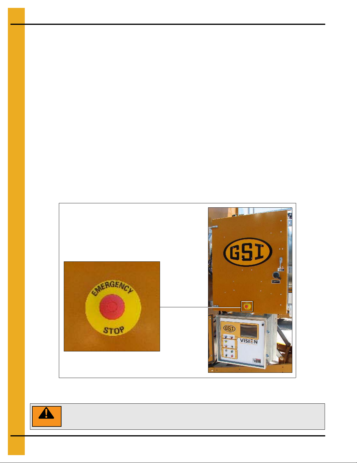
WARNING
Pushing the Emergency Stop switch does not interrupt the main power to the
upper control box panel.
Dryer Operation
Thank you for choosing a GSI product. It is designed to give excellent performance and service for
many years.
This manual describes the operation and service for all standard production model dryers. These models
are available for liquid propane or natural gas fuel supply, with either 1 phase 230 volt, or 3 phase
230 or 440 volt electrical power.
Our foremost concern is your safety and the safety of others associated with this equipment. We want to
keep you as a customer. This manual is to help you understand safe operating procedures and some
problems which may be encountered by the operator and other personnel.
As owner and/or operator, it is the responsibility to know what requirements, hazards, and precautions
exist, and to inform all personnel associated with the equipment or in the area. Safety precautions may be
required from the personnel. Avoid any alterations to the equipment. Such alterations may p roduce a very
dangerous situation where SERIOUS INJURY or DEATH may occur.
This equipment shall be installed in accordance with the current installation codes and applicable
regulations which should be carefully followed in all cases. Authorities having jurisdiction should be
consulted before installations are made.
Emergency Stop Switch
The Emergency Stop switch is located on the upper control box door. Pushing the Emergency
Stop switch will interrupt the control power and stop all dryer functions.
6 PNEG-1935 Vision Hybrid for Portable Dryers
Page 7

1. Safety
Safety Precautions
READ THESE INSTRUCTIONS BEFORE INSTALLATION AND OPERATION
SAVE FOR FUTURE REFERENCE
1. Read and understand the operating manual before attempting to operate the dryer.
2. NEVER operate the dryer while the guards are removed.
3. Power supply should be OFF for service of electrical components. Use CAUTION in checking voltage
or other procedures requiring the power to be ON.
4. Check for gas leaks at all gas pipe connections. If any leaks are detected, DO NOT operate dryer.
Shutdown and repair before further operation.
5. NEVER attempt to operate the dryer by jumping or otherwise bypassing any safety devices on
the unit.
6. Set pressure regulator to avoid excessive gas pressure being applied to the burner during ignition
and when the burner is in operation. DO NOT exceed maximum recommended drying temperature.
7. Keep the dryer clean. DO NOT allow fine material to accumulate in the plenum chamber.
Clean grain is easier to dry. Fine material increases resistance to airflow and requires removal
of extra moisture.
8. Keep auger drive belts tight enough to prevent slippage.
9. Use CAUTION in working around high speed fans, gas burners, augers and auxiliary conveyors
which can START AUTOMATICALLY.
10. Keep area around air inlet to the fan clear of any obstacles and combustible materials.
11. BEFORE attempting to remove and reinstall any propeller, make sure to read the
recommended procedure.
12. Make sure that capacities of auxiliary conveyors are matched to dryer auger capacities.
13. DO NOT operate in an area where combustible material will be drawn into the fan.
14. The operating and safety recommendations in this manual pertain to the common cereal
grains as indicated. When drying any other grain or products, consult the factory for
additional recommendations.
15. Routinely check for any developing gas plumbing leaks. Check LP vaporizer for contact with
burner vanes.
PNEG-1935 Vision Hybrid for Portable Dryers 7
Page 8

1. Safety
Use Caution in the Operation of this Equipment
This dryer is designed and manufactured with operator safety in mind. However, the very nature of a grain
dryer having a gas burner, high voltage electrical equipment and high speed rotating parts, presents
hazards to personnel which cannot be completely safeguarded against withou t interfering with the efficient
operation of the dryer and reasonable access to its components.
Use extreme caution in working around high speed fans, gas-fired heaters, augers and auxiliary
conveyors, which may start without warning when the dryer is operating on automatic control.
Continued safe, dependable operation of automatic equipment depends, to a great degree, upon the owner.
For a safe and dependable drying system, follow the recommendations within the Owner’s Manual and make
it a practice to regularly inspect the unit for any developing problems or unsafe conditions.
Take special note of the Safety Precautions on Page 7 before attempting to operate the dryer.
8 PNEG-1935 Vision Hybrid for Portable Dryers
Page 9
2. Decals
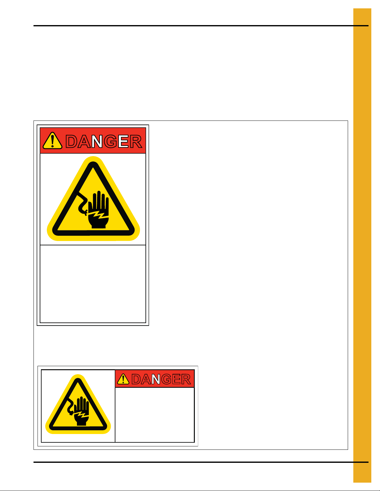
DANGER
DC-1224
High voltage.
Will cause serious
injury or death.
Lockout power
before servicing.
DANGER
HIGH VOLTAGE
Will cause injury
or death.
Lockout power
before servicing.
DC-889
GSI Group Inc. 217-226-4421
Decal: DC-889
Decal DC-889 has two locations. One inside the
fan/heater control box and another on the dryer upper
control box door next to the main power disconnect.
Decal: DC-1224
Decal DC-1224 is located in two places on the fan/heater control box.
One on the lid and one on the front of the fan/heater control box.
Another location for this decal is inside the upper control box for the dryer.
The GSI Group recommends contacting the local power company and having a representative surve y the
installation so the wiring is compatible with their system and adequate power is supplied to the unit. Safety
decals should be read and understood by all people in the grain handling area.
If a decal is damaged or is missing, contact:
GSI Decals
1004 E. Illinois St.
Assumption, IL. 62510
Phone: 1-217-226-4421
A free replacement will be sent to you.
PNEG-1935 Vision Hybrid for Portable Dryers 9
Page 10
2. Decals
DC-972
WARNING
Moving parts can crush
and cut. Keep hands
clear. Do not operate
without guards in place.
Failure to do so could
result in serious injury.
GSI Group 217-226-4421
DANGER
Rotating auger will crush
and cut. Auto equipment
can start at anytime. Do not
enter until electric power is
locked in off position. Failure
to do so will result in serious
injury or death.
GSI Group 217-226-4421 DC-974
Automatically controlled
belt drive can start at
anytime. Keep hands
clear. Failure to do so
could result in serious
injury.
GSI Group 217-226-4421
DC-971
WARNING
Decal: DC-972
Decal DC-972 is located on the bottom auger belt guard and the front bearing
plate (which is visible when the bottom auger belt guard is removed).
An alternate location would be at the rear of the dryer for portable dryers
equipped with the Front Discharge Option.
Decal: DC-971
Decal DC-971 is located on the bottom auger belt guard and the front bearing plate
(which is visible when the bottom auger belt guard is removed). An alternate location
would be at the rear of the dryer for portable dryers equipped with the
Front
Discharge Option
.
Another location for decal DC-971 is on the top of the auger belt guard (one on the
belt guard cover and one on the inside belt guard body visible when the belt guard
cover is removed).
Decal: DC-974
Decal DC-974 has several different locations. Two are located on the front end panel
below the fan/heater. Two are located on the rear end panel below the rear access
door. Two are located on the auger discharge box (one on the outside top and one on
the inside of the flapper lid next to the discharge mercury switch). One more of these
decals is located inside the plenum on the rear plenum closure door just inside the rear
access door.
10 PNEG-1935 Vision Hybrid for Portable Dryers
Page 11
DC-1229
WARNING
Rotating metering roll.
Equipment can start
automatically. Keep hands
clear. Can cause serious
injury. Disconnect power
before servicing.
Decal: DC-1229
Decal DC-1229 is located on each of
the meter roll access doors.
Automatic equipment can
start at any time. Do not
enter until fuel is shut off
and electrical power is
locked in off position.
Failure to do so will result
in serious injury or death.
DC-973
DANGER
GSI Group 217-226-4421
Decal: DC-973
Decal DC-973 is located on the rear plenum access door (inside and outside).
Flame and pressure beyond
door. Do not operate with
service door removed. Keep
head and hands clear. Can
cause serious injury.
DC-1227
WARNING
GSI Group 217-226-4421
Decal: DC-1227
Decal DC-1227 is located on the
fan/heater access door.
2. Decals
PNEG-1935 Vision Hybrid for Portable Dryers 11
Page 12
2. Decals
DC-1249
Dryer must be
towed empty and
in accordance
with state and
provincial
regulations.
HUB TEMPERATURE
TIGHTEN TO
90FT-LBS.
55-60 PSI
COLD
CHECK AFTER 50 MILES AND EVERY 200 MILES
050
100
150
200 250
NO GREATER THAN 150°F
150°
16-17"
3/4" MINIMUM
BOLT DIAMETER
DC-388
Hitch pin must be
securely fastened and
no less than 3/4" in
diameter. Failure to
follow installation
instructions may result
in property damage.
Decal: DC-388
Decal DC-388 is located on the hitch tongue.
Decal: DC-1249
Decal DC-1249 is located on the hitch tongue.
DC-1225
Stay clear of rotating
blade. Blade could start
automatically. Can cause
serious injury. Disconnect
power before servicing.
DC-1225GSI Group 217-226-4421
WARNING
Decal: DC-1225
Decal DC-1225 is located on the fan/heater
access door.
12 PNEG-1935 Vision Hybrid for Portable Dryers
Page 13
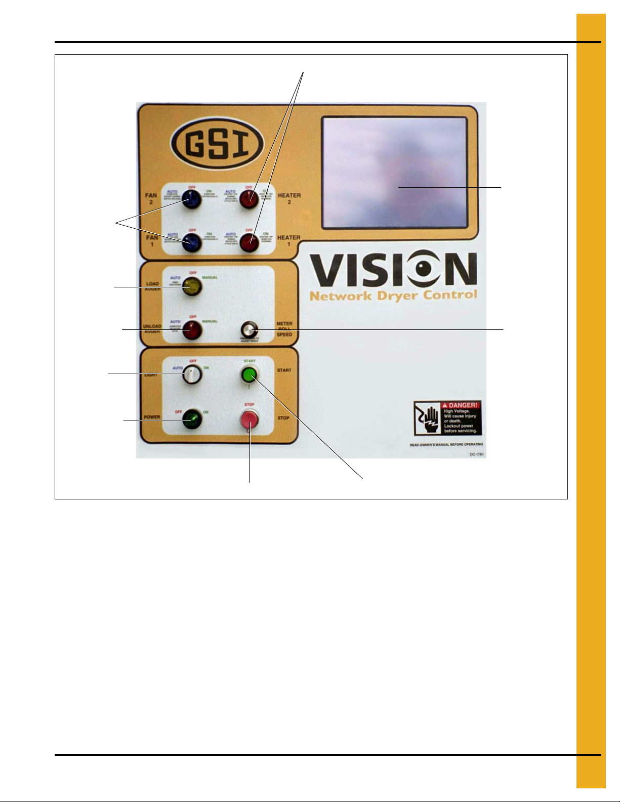
3. Vision Control Panel
Fan switches
Load switch
Unload switch
Outside
Light switch
Control
Power switch
Stop button
Start switch
Meter Roll
Adjustment
Touch screen
Heater switches
Control Power Switch
The Vision control system is turned ON or OFF with this switch.
NOTE:
Stop Button
This button stops all dryer functions. If an automatic dryer shutdown occurs, first determine and correct
the cause of the shutdown. Then, press the Stop button to reset the dryer before restarting.
PNEG-1935 Vision Hybrid for Portable Dryers 13
Figure 3A
This switch does not disconnect the power that is present at the breakers, contactors, transformer(s),
fuses or other electrical components found in the upper and lower control boxes. Turn the main
disconnect handle to the OFF position prior to servicing any of the installed components.
Page 14
3. Vision Control Panel
Outside Light Switch
The dryers outside service light is turned ON or OFF here. It also can be set on AUTO, which turns the
light ON while the dryer is running and OFF if a shutdown occurs.
Start Button
Push the Start button and all of the selector switches on the control panel will be activated.
Unload Switch
The Unload switch turns the metering rolls and discharge auger ON or OFF and selects the operation of
the metering rolls. In the MANUAL position, the meter rolls will operate in one Speed only. In the AUTO
position, the meter rolls switch to a multi-speed mode for moisture control operation. The switch will
illuminate whenever the load auger is operating.
NOTE: If the unload auxiliary controls are being used, this switch will also control the operation of the
auxiliary equipment.
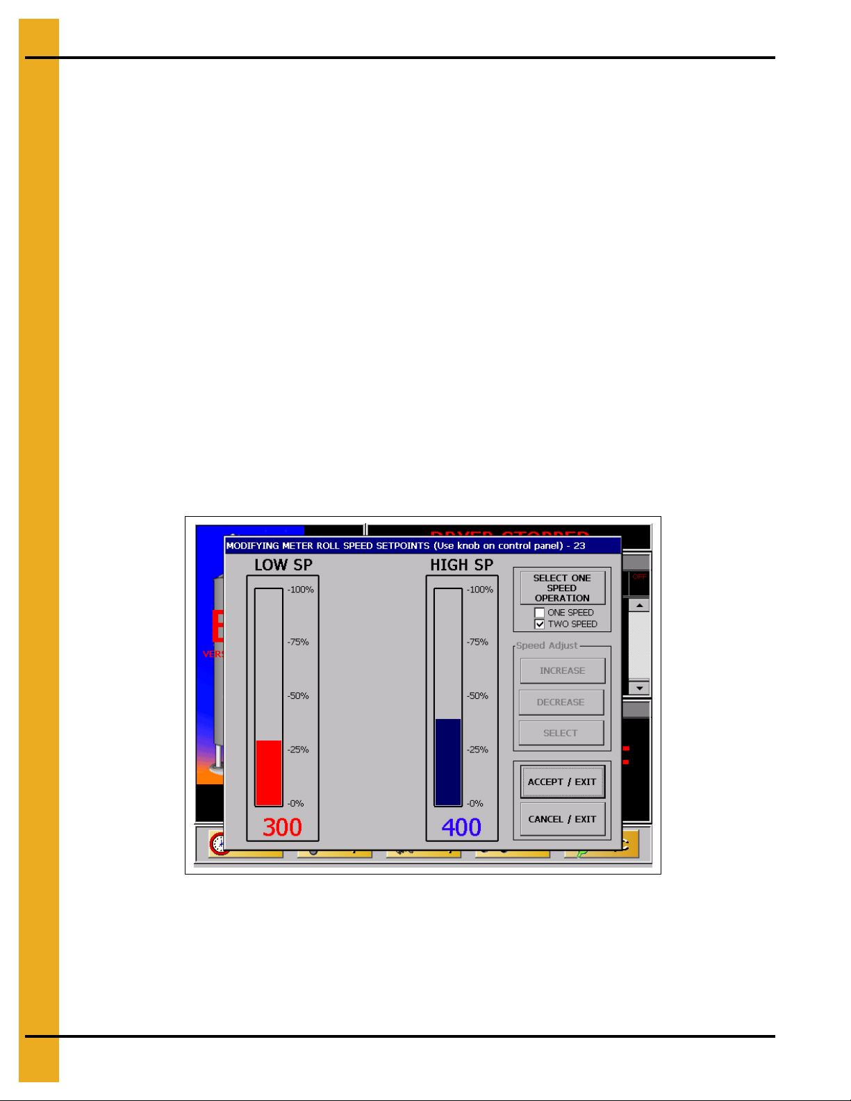
Meter Roll Adjustment
This knob allows the user to adjust the meter roll setpoint(s). Pressing the knob will bring up the “Modifying
Meter Roll Speed Setpoints” screen. (See Figure 3B.)
Figure 3B
NOTE: Screen may vary depending on the moisture control scheme selected.
Turning the knob clockwise will adjust the selected (red color) setpoint in a positive direction and vice
versa. Pressing the knob will switch between setpoints.
14 PNEG-1935 Vision Hybrid for Portable Dryers
Page 15

3. Vision Control Panel
Here, you will find the following options:
Speed Adjust buttons: These are used to adjust the setpoints if the Meter Roll Knob is disabled by
the software. For instructions on doing this, see Operations Chapter on Page 21.
Accept/Exit: To store the parameters and exit the screen.
Cancel/Exit: To disregard the changes and exit the screen.
Load Switch
This is used to select the operation of the fill auger. In both the AUTO and MANUAL positions, the load
auger will operate if the dryer is low on grain and will automatically shut OFF when the dryer is full. In the
AUTO position, the dryer will shutdown if the out of grain timer expires. The load delay is disabled
when the Load switch is in the MANUAL position. The switch will illuminate whenever the load auger
is operating.
Fan Switch
Each fan can be selected as ON, OFF or AUTO. The ON position operates the fan continuously during
staged batch and continuous flow modes. The AUTO position operates the fan in staged batch during the
dry and cool cycle, but the fan will turn OFF during the unload cycle. This switch will illuminate whenever
the Air Pressure switch, located in the proper plenum chamber, is sensing air pressure.
NOTE: The bottom fan on the dryer is always Fan one.
Heater Switch
Each heater can be selected as ON, OFF or AUTO with this switch. The AUTO position activates the
burner in staged batch during the dry cycle only. The ON position will activate the burner when the fan is
running and if air pressure is detected. The switch will illuminate only when the flame sensor detects
the flame.
NOTE: The bottom heater on the dryer is always Heater one.
PNEG-1935 Vision Hybrid for Portable Dryers 15
Page 16
4. Boot Screen
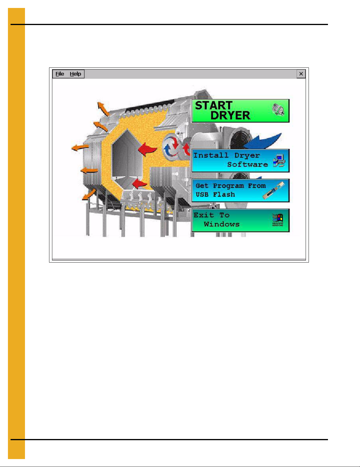
Boot Screen Description and Button Explanations
Turning the Control Power switch to the ON position, will start the Vision computer. The first screen to
appear will be the Boot Screen. Notice that there are four (4) buttons on the Boot Screen. (See Figure 4A.)
Figure 4A
1. Start Dryer: This button accesses the dryer program.
2. Install Dryer Software: This button is used in updating the Vision software, which is described
further in this chapter.
3. Get Program From USB Flash: This button is used in updating the Vision software, which is
described further in this chapter.
4. Exit To Windows: This button should NOT be used in normal operation. Only the GSI Group
employees should press this button. Turn the Control Power switch OFF, then ON if this button is
inadvertently pushed to return to the regular Boot Screen.
16 PNEG-1935 Vision Hybrid for Portable Dryers
Page 17
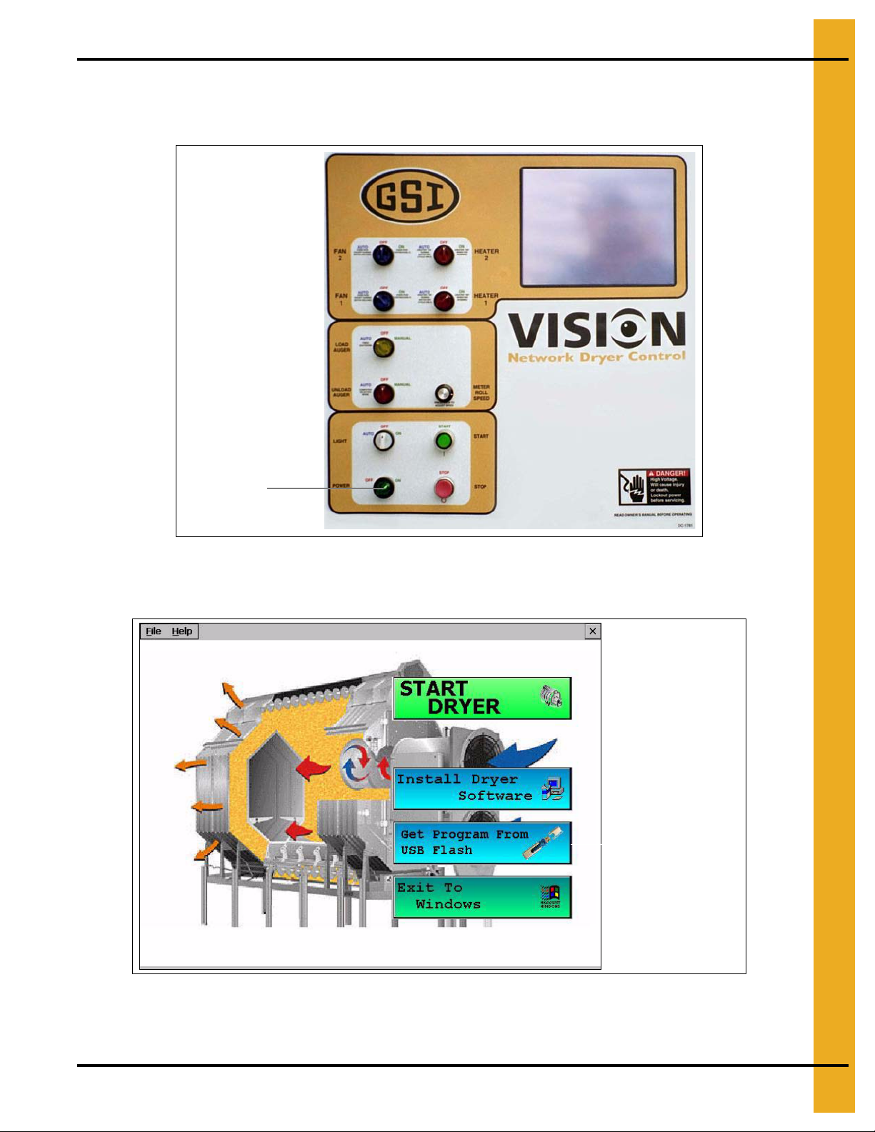
Software Update Procedure
Control
Power switch
Get Program From
USB Flash button
1. Cycle the Control Power switch. The Vision computer will start. (See Figure 4B.)
4. Boot Screen
Figure 4B
2. When the “Boot Screen” appears, touch the “Get Program From USB Flash” button. (See Figure 4C.)
PNEG-1935 Vision Hybrid for Portable Dryers 17
Figure 4C
Page 18
4. Boot Screen
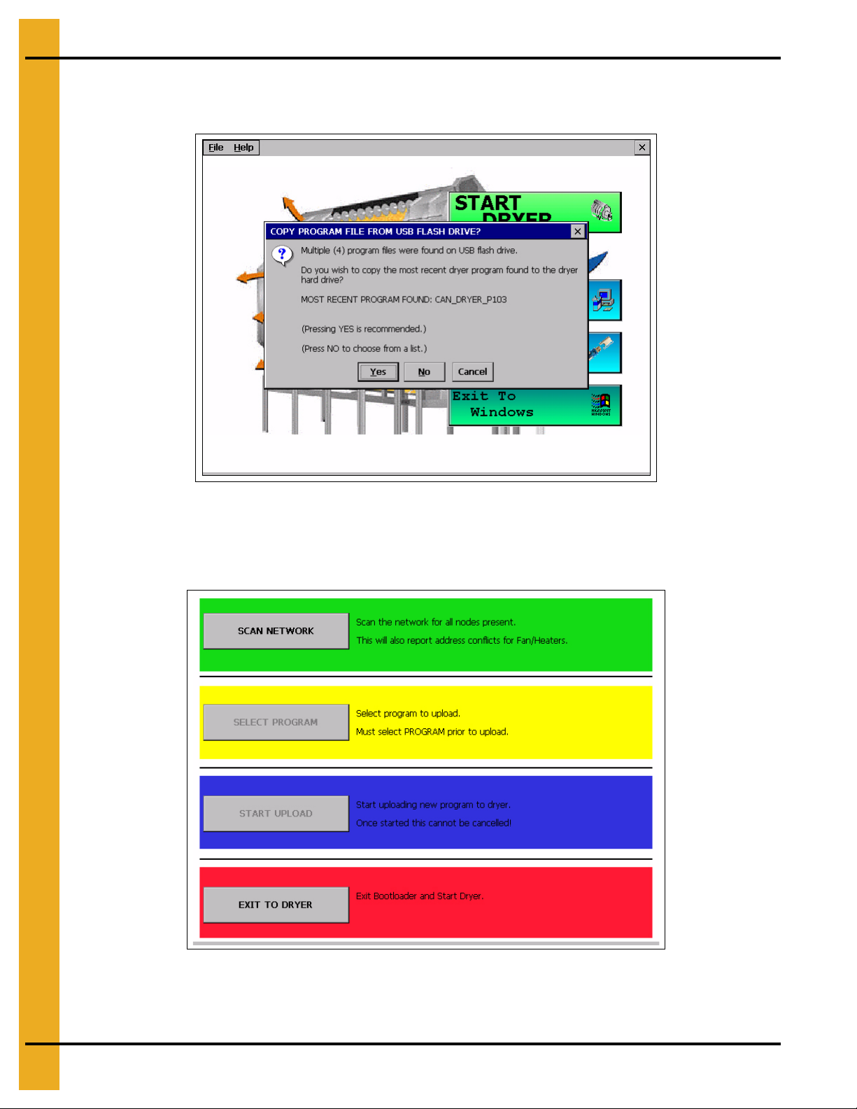
3. Insert USB flash drive into USB port.
4. The display will now confirm that program files were found.
Figure 4D
Press “Yes” to copy.
5. After the program files are transferred, the “Boot Loader” screen will appear. (See Figure 4E.)
Figure 4E
18 PNEG-1935 Vision Hybrid for Portable Dryers
Page 19
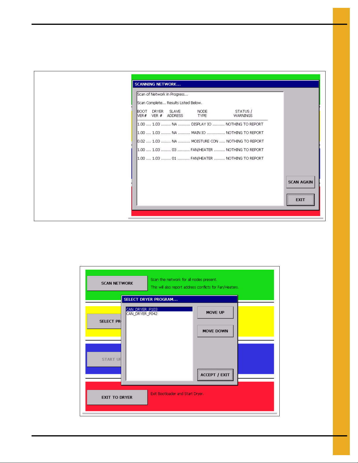
4. Boot Screen
NOTE: A Display I/O, Main I/O,
Moisture Control and one entry for
each Fan/Heater on the dryer
should appear.
Select the “Scan Network” button. This scan will check the dryer to make sure all parts of the control
system are communicating directly.
6. After the scan is complete, the Display I/O, Main I/O, Moisture Control and the Fan/Heater(s) sho uld
be shown as “Nothing to Report”. (See Figure 4F.)
Touch the “Exit” button.
7. Choose the “Select Program” button from the “Boot Loader” screen. (See Figure 4G.)
Figure 4F
Figure 4G
PNEG-1935 Vision Hybrid for Portable Dryers 19
Page 20
4. Boot Screen
8. Select the program file you wish to upload by touching the “Move Up” and “Mo ve Down” buttons until
the desired program file is highlighted. Then, choose the “Accept/Exit” button.
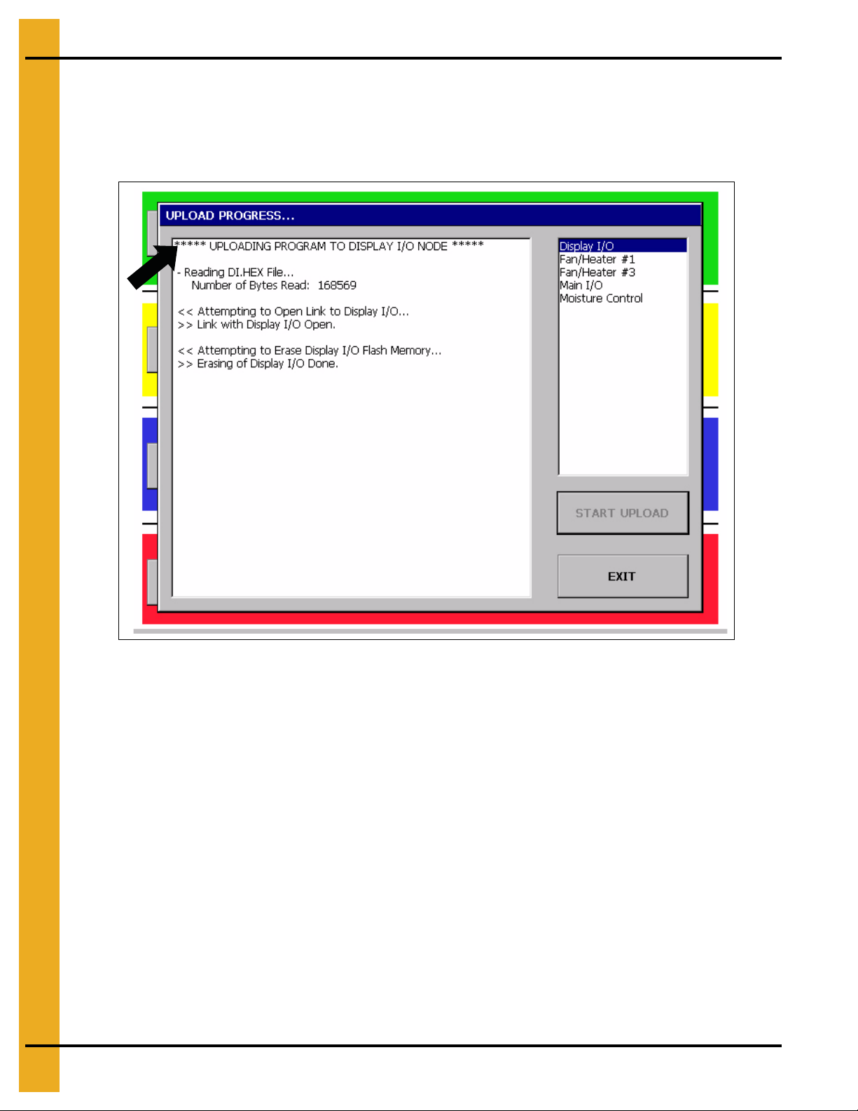
9. Touch the “Start Upload” button.
10. When the “Upload Progress” screen appears, select the “Start Upload” button. (See Figure 4H.)
Figure 4H
11. The Vision computer will now begin programming each of the network circuit boards on the dryer.
The box on the right of the screen lists the network circuit boards detected in the scan. Each circuit
board listed will have to be reprogrammed, so this may take a few minutes. File upload progress for
the circuit board that is highlighted is displayed in the box on the left. (See Figure 4H.)
12. Once the upload is complete, choose the “Exit to Dryer” button to leave the “Boot Loader” screen and
start the dryer.
13. The dryer will begin running the program that was just installed.
14. The dryer control is now ready to operate the dryer.
15. In the event it is determined that reversion to the previous software version is necessary, go back to
the Boot Screen and select “Install Dryer Software” and follow the instructions above to re-install the
previous software.
20 PNEG-1935 Vision Hybrid for Portable Dryers
Page 21
5. Operations
Dryer Operation
Animation
Dryer St atus
Dryer Status
Charts
Plenum(s)
Configuration
Buttons
Operations
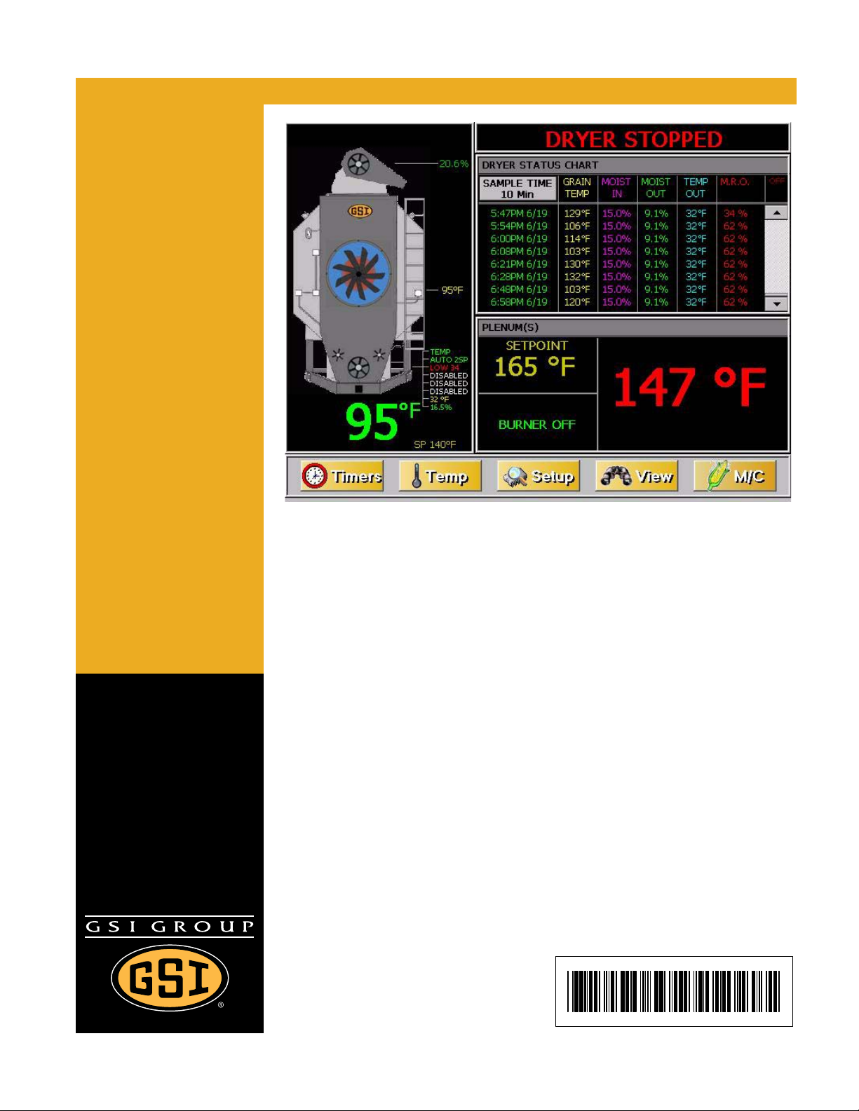
NOTE: The following screenshots are taken from various models of portable dryers, explaining why the
picture on the screen in this manual, may be different than that of the display.
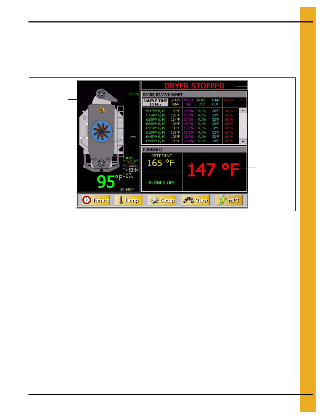
Default Operation Screen
Figure 5A
The “Operation Screen” is divided into five (5) sections. (See Figure 5A.)
1. Dryer Operation Ani mation: Located on the left side of the “Operation Screen”, the dryer ope ration
animation shows the status of the fans/heaters, load and unload augers and meter rolls. It will also
display the grain temperature, moisture content, moisture control setpoint and the bushel counter.
2. Dryer Status: Located at the very top of the right side of the “Operation Screen”, the drye r status will
tell the user if the dryer is stopped, started, loading or unloading.
3. Dryer Status Chart: This chart, located directly under dryer status, will sh ow the grain temperature,
moisture in/out, temperature out and meter roll output (M.R.O) over a period of time.
4. Plenum(s): Located directly below dryer status chart, the plenum section will show temperature
setpoint, actual plenum temperature and burner status.
5. Configuration Buttons: Select from “Timers”, “Temp”, “Setup”, “View” and “M/C” buttons.
PNEG-1935 Vision Hybrid for Portable Dryers 21
Page 22
5. Operations
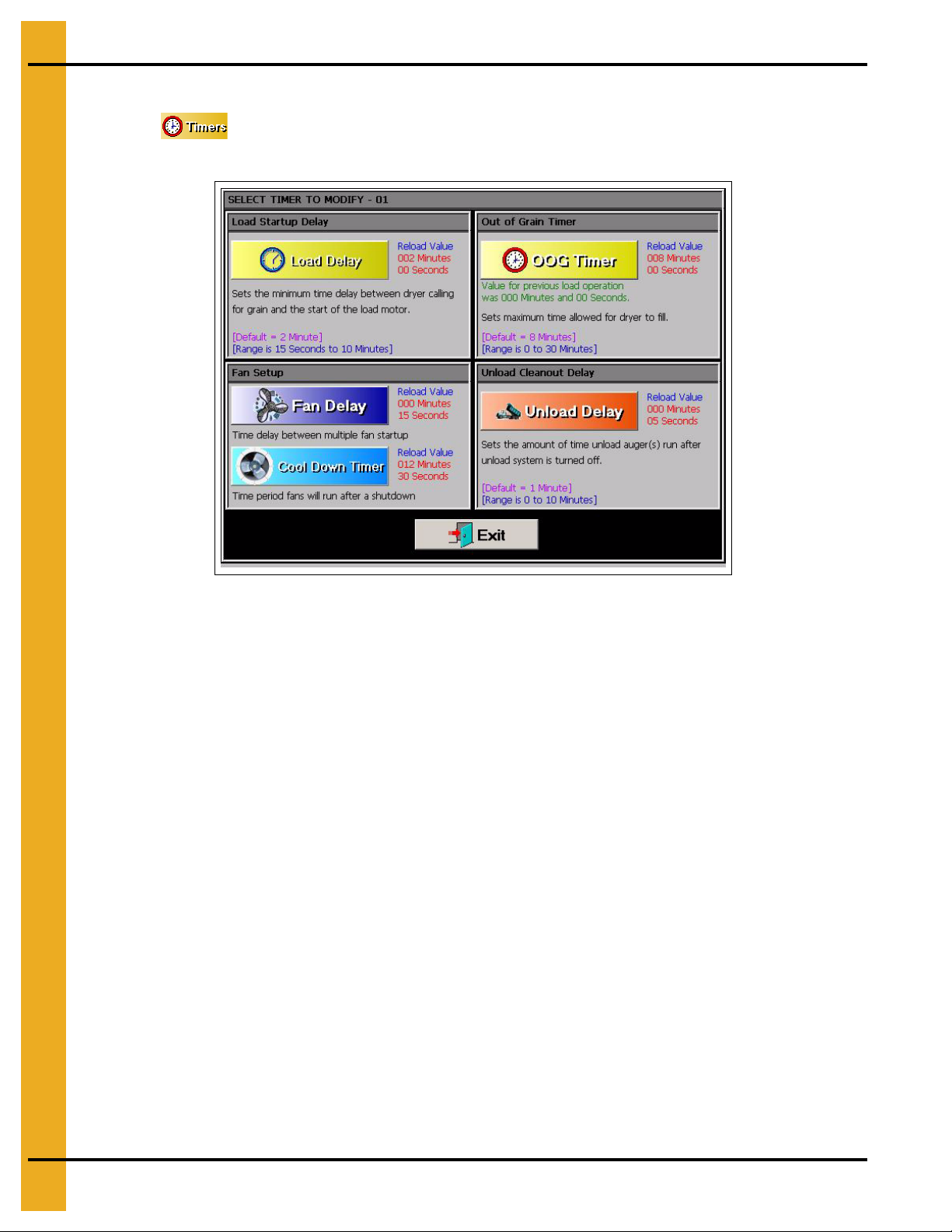
Timers Button
Select the button. A new screen will appear called the “Select Timer to Modify” screen.
(See Figure 5B.) There are five (5) timers that can be modified.
Figure 5B
1. Load Delay: (Default setting - 2 minutes) This delay is used to prevent the load auger from
over-cycling. The load delay is active only when the Load switch is in the AUTO position. The timer
starts when the dryer calls for grain.
2. Out Of Grain (OOG) Timer: (Default setting - 8 minutes) The “OOG” timer should be set to the
maximum time it takes for the dryer to refill during continuous or batch drying modes. The computer
will display the time required to fill the dryer on the previous load, aiding you in setting an accurate
time. If the dryer runs out of grain while the Load switch is in the AUTO position, the “OOG” timer
automatically shuts off the dryer after the period of time preset on the timer.
3. Fan Delay: (Default setting - 3 seconds) The “Fan Delay” timer controls the amount of time between
each fan startup to reduce the dryer inrush amperage.
4. Unload Delay: (Default setting - 1 minute) The “Unload Delay” timer is used to regulate the amount
of time the unload auger runs after the metering rolls stop.
5. Cool Down: (Default setting - zero seconds) The dryer fans will operate for a “Cool Down” period in
the event that the dryer experiences a shutdown, other than that of a plenum, grain high temperature
or fan motor overload situation. The dryer can also be restarted by pressing the “Start” button on
the front of the Vision control panel. This prevents the fans from shutting down because of
nuisance warnings.
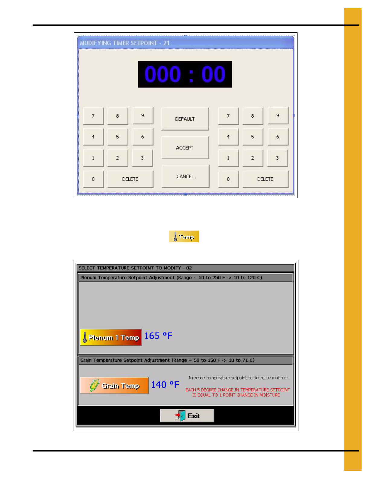
To change a timer setpoint, touch the button of the timer you wish to modify. The “Modifying Timer
Setpoint” screen will then be displayed, which is shown in Figure 5C on Page 23. T he left nu mber pad is
used to modify the minutes and the right number pad will modify the seconds. Touching the “Default”
button will automatically set the timer to the default setpoint for that timer. The “Accept” button will save
the displayed time as the setpoint. Choosing “Cancel” will exit the “Modifying Timer Setpoint” screen
without saving any changes and the timer will stay at the currently saved setpoint.
22 PNEG-1935 Vision Hybrid for Portable Dryers
Page 23
5. Operations
Figure 5C
Temp Button
To adjust the temperature setpoints, touch the button at the bottom of the “Operation Screen”.
A new screen will appear called the “Select Temperature Setpoint to Modify” screen. (See Figure 5D.)
Figure 5D
PNEG-1935 Vision Hybrid for Portable Dryers 23
Page 24
5. Operations
Modify the setpoint for each of the temperatures by selecting the corresponding button.
Plenum Temperature Setpoint - Press the “Plenum X Temp” button to change the individual
plenum setpoints. The “X” refers to a number between 1 and 6. Plenum #1 refers to the heater closest
to the ground.
Grain Temperature Setpoint - This setpoint is used for all temperature based moisture control
schemes. For more information, see the Moisture Control Options Chapter on Page 38.
The plenum temperature setpoint range is 50 F-250 F. The current temperature setpoint is displayed next
to the corresponding “Plenum” button.
The grain temperature setpoint range is 50 F-160 F. The current temperature setpoint is displayed next to
the “Grain Temperature” button.
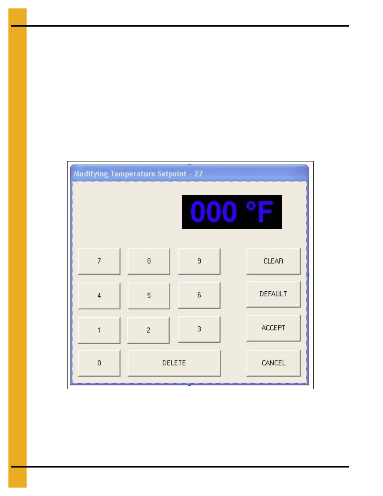
Touch the desired plenum button of the setpoint you wish to change. The “Modifying Temperature
Setpoint” screen will appear. (See Figure 5E.)
Figure 5E
Enter the desired temperature using the displayed number pad, t hen touch the “Accept” button. Touch ing
the “Cancel” button will return you to the “Select Temperature Setpoint to Modify” screen without
saving changes.
24 PNEG-1935 Vision Hybrid for Portable Dryers
Page 25
5. Operations
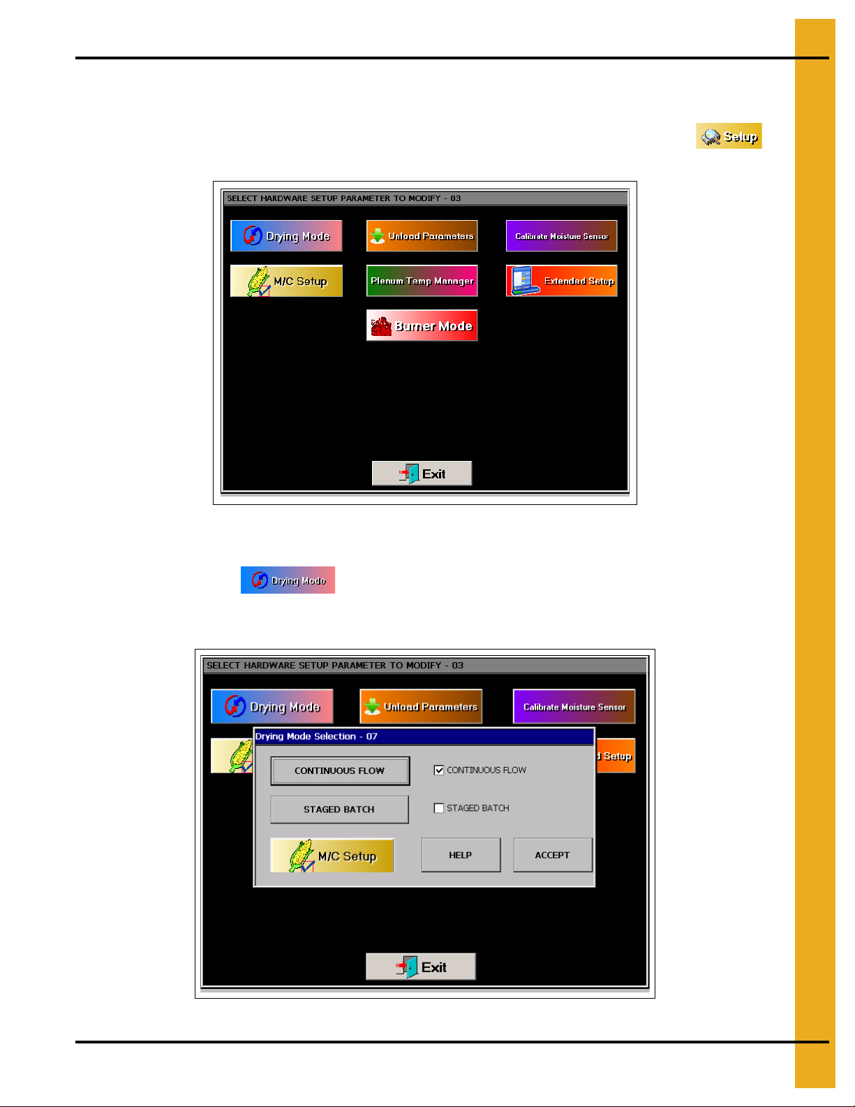
Setup Button
The Setup screen will allow you to configure other parameters of the dryer. To access the “Select
Hardware Setup Parameter to Modify” screen, also known as the “Setup Screen”, touch the
button. (See Figure 5F.)
Figure 5F
The following list can be modified:
1. Drying Mode: The button will display the “Drying Mode Selection” window. Select
continuous flow or staged batch. A check mark is displayed next to the currently selected drying
mode. (See Figure 5G.)
Figure 5G
PNEG-1935 Vision Hybrid for Portable Dryers 25
Page 26
5. Operations
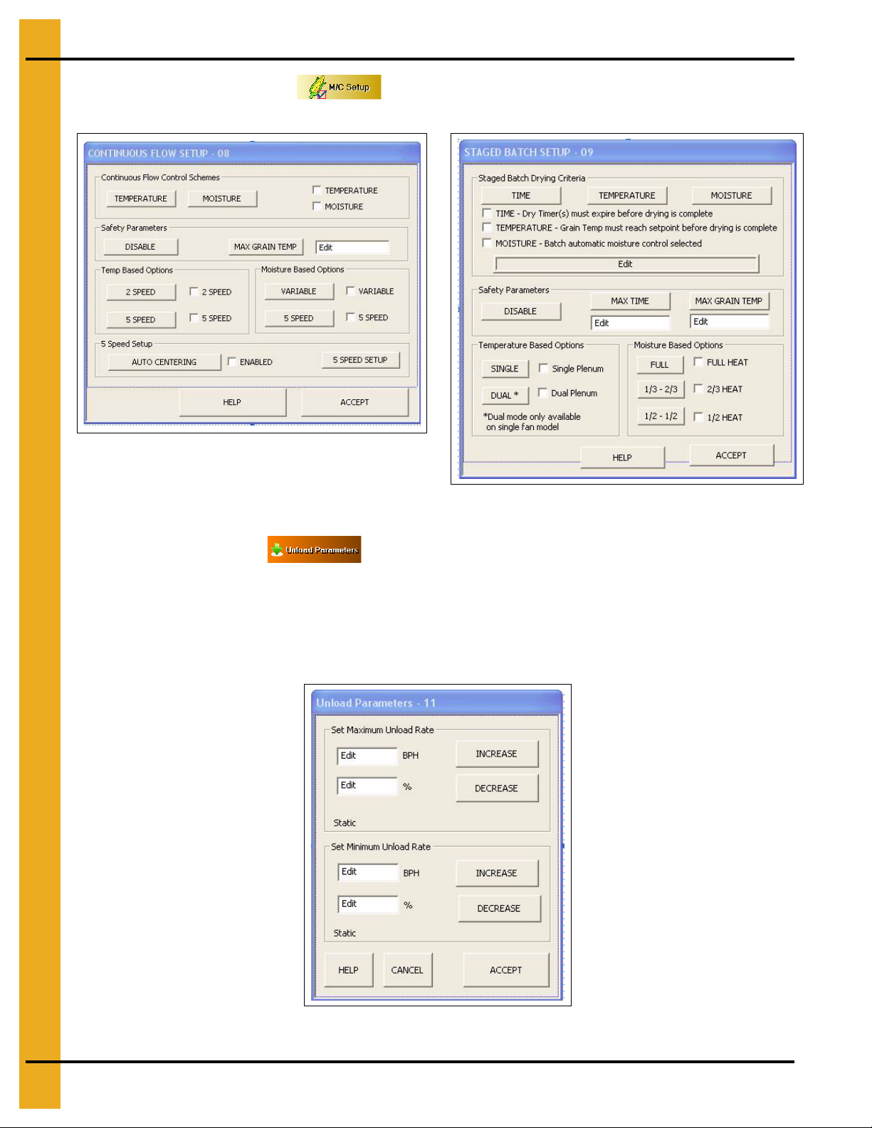
2. Moisture Control Setup: The moisture control setup operations are described in
greater detail in the Moisture Control Options Chapter on Page 38.
Figure 5H
Figure 5I
3. Unload Parameters:
a. Set Maximum Unload Rate: The meter roll speed set point cannot be set higher than this value.
This prevents choking downstream augers.
b. Set Minimum Unload Rate: The meter roll speed setpoint cannot be set lower than this value.
(See Figure 5J.)
Figure 5J
26 PNEG-1935 Vision Hybrid for Portable Dryers
Page 27
5. Operations
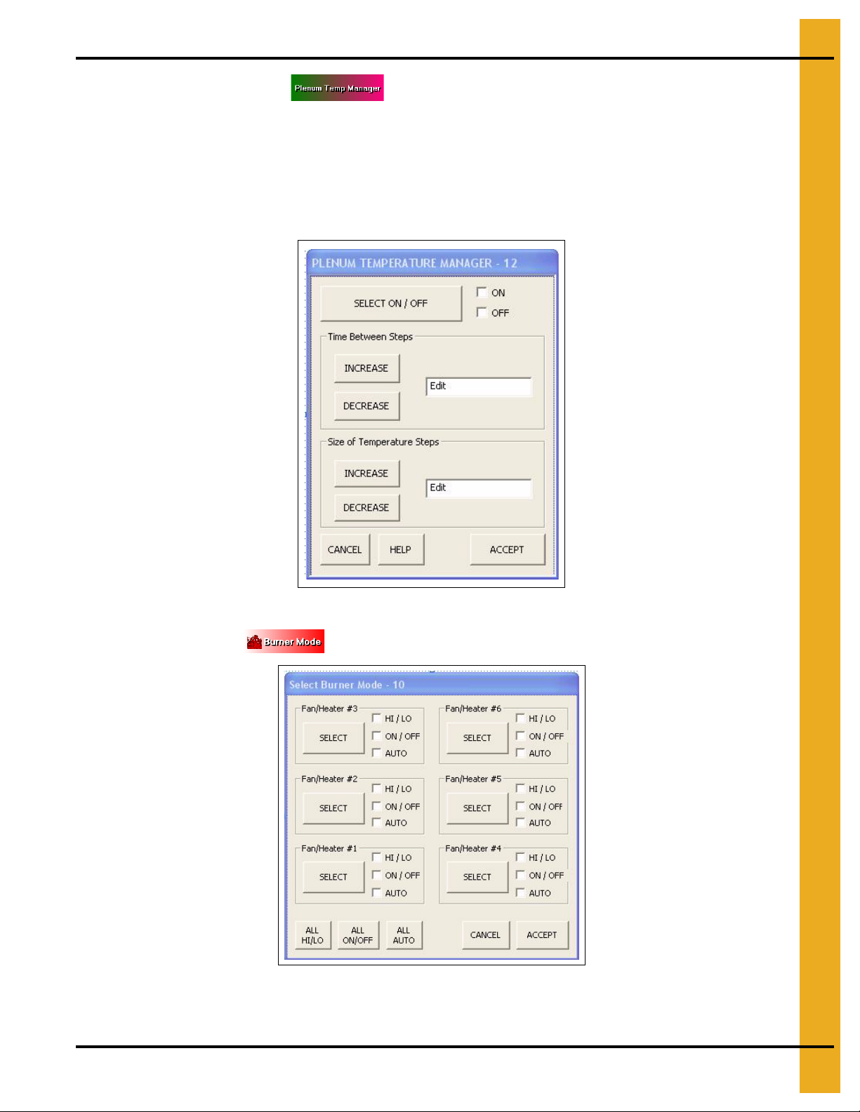
4. Plenum Temp Manager: This will reduce the plenum temperature setpoint(s) if the
unload rate reaches its maximum allowable value for the time specified by the “Time Between Steps”
menu. Once the time has been exceeded, the dryer will reduce the temperature setpoint(s) by the
value given in the “Size of Temperature Step”. If the unload rate falls below the maximum allowable
value for the “Time Between Steps” period, the temperature setpoint(s) will be increased by the “Size
of Temperature Steps” until the original setpoints are met. (See Figure 5K.)
NOTE: Default setting is “OFF”.
5.
Burner Mode:
The button will display the “Select Burner Mode” screen.
NOTE: The bottom heater is always Heater one.
Figure 5K
(See Figure 5L.)
Figure 5L
PNEG-1935 Vision Hybrid for Portable Dryers 27
Page 28
5. Operations
The “Select Burner Mode” screen will allow the operator to select the type of burner operation for
each burner. The user has three (3) options: HI/LO, ON/OFF and AUTO modes.
a. HI/LO Mode (Default Setting): The burner will switch from high heat to low heat when the
plenum temperature setpoint has been reached.
b. ON/OFF Mode: The burner will shut OFF when the upper temperature setpoint has been
reached and turn back on when the lower temperature setpoint has been met.
NOTE: Useful for low plenum temperature settings in warm conditions.
c. AUTO Mode: All burners in HI/LO will be started. If the burner stays in “Low-Fire” for 60 seconds
or the plenum temperature exceeds the setpoint plus 20° for 10 seconds, that burner will switch
to ON/OFF operation.
NOTE: Useful in very warm ambient temperature conditions.
To select modes, touch the “Select” button for the fan/heater you wish to change. Touching the
“ALL HI/LO” button will set all burners to HI/LO and the same procedure can be duplicated for the
“ALL ON/OFF” and “ALL AUTO” buttons. Choose the “ACCEPT” button to save any changes and
return to the “Setup Screen” or choose “CANCEL” to return to the “Setup Screen” without saving
any changes.
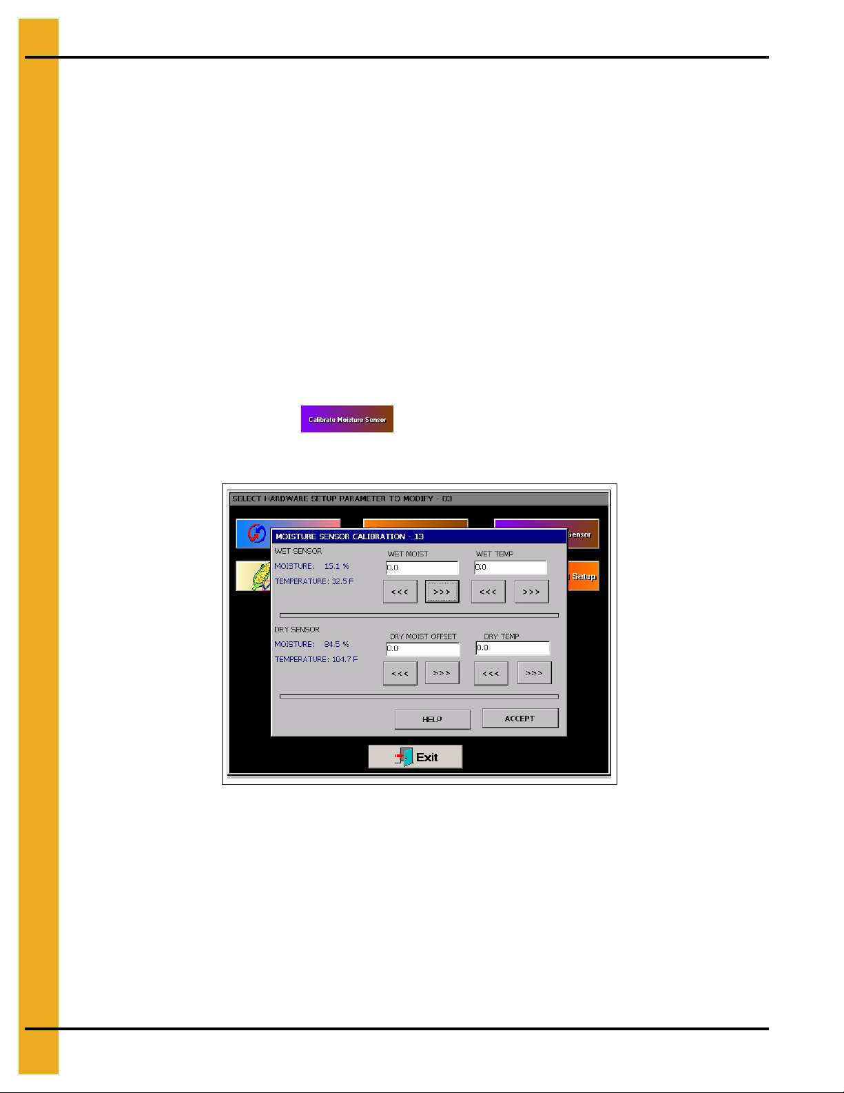
6.
Calibrate Moisture Sensor:
dryer - one for incoming grain (wet) and another for outgoing (dry). Each device has one moisture
and one temperature sensor included. (See Figure 5M.)
There are two (2) moisture/temperature sensors per
Figure 5M
Calibrating moisture: Take several moisture samples of the grain over an extended period of
time, average these values and calibrate the sensors accordingly.
Example: If the dryer’s exiting moisture (dry) is reported at 15.5% on the Vision screen and the
averaged samples yielded a value of 15%, then the calibration screen would be used to enter
-0.5% as the “Dry Moist Offset”.
Calibrating temperature: Take several temperature samples of the grain over an extended
period of time, average these values and calibrate the sensor accordingly.
Example: If the dryer’s incoming temperature (wet) is reported to be 105°F on the Vision scree n
and the average samples yield a value of 100°F, adjust the “Dry Temp” to -5.
28 PNEG-1935 Vision Hybrid for Portable Dryers
Page 29

7.
Extended Setup Screen
The following list can be modified here:
1. Diagnostics:
5. Operations
Figure 5N
Check Light Outputs: Allow the user to verify the controller is attempting to illuminate each
individual switch. If there is a check mark present on the Vision screen, the corresponding
switch should be lit. If not, there is a wiring issue.
Check Switch Wiring: Allows user to verify the controller is recognizing switch positions
correctly. If the “Fan 1” switch is in the “AUTO” position, the “FAN 1 AUTO” box should be
checked. If not, there is a wiring issue.
Set MR Speed Via Screen: Normally, the meter roll adjustment knob on the control panel
is used to set the metering roll setpoint. In the event of a knob malfunction, the metering roll
setpoint can be adjusted by this screen.
Calibrate Moisture Sensors: Previously mentioned in the preceding “Setup Screen”
section on Page 25. This is just another way to access those settings.
2. Differential: The button will display the “Modifying Burner Differential Settings”
screen. (See Figure 5O on Page 30.) Adjusting the burner differential settings allows the
operator to keep the plenum temperature within a certain range.
NOTE: 1° is the default and preferred setting.
PNEG-1935 Vision Hybrid for Portable Dryers 29
Page 30

5. Operations
Example: If you have the temperature setpoint at 180°F and you select +/- 3° as the burner
differential, then the burner will switch to low heat at 183°F and back to high heat at 177°F.
To modify a burner differential setting, touch the plenum button you wish to modify, then
select one of the five (5) differential setting buttons on the right side of the screen. The
“Accept/Exit” button will save the settings and return to the “Setup Screen”.
Figure 5O
3. Printer Setup: The option was available on select portable dryers from
2006-2009. The option was taken away in 2009 and is no longer available. However, printer
setup is still available for those previously installed printers.
4. Meter Roll Reverse (4" only): The button aids in cleaning out the fine
material that builds up over the course of a drying season. This button will toggle between
normal meter roll operation and reversed. If the option is checked, the meter roll moves
forward for 55 minutes and in reverse for 5 minutes before the cycle is started again.
5. BPH Calibration: The button will display the “Unload Bushels Setup” screen.
(See Figure 5P.) The bushel counter can be cleared by touching the “Clear” button. The bushel
counter can be calibrated by touching the “Increase” and “Decrease” buttons.
Figure 5P
30 PNEG-1935 Vision Hybrid for Portable Dryers
Page 31

5. Operations
6. Set Time/Date: The button will display the “Set Time/Date” window.
(See Figure 5Q.)
Figure 5Q
Use the “Up” and “Down” buttons to change each of the parameters. “Accept/Exit” will save
settings and return to the “Setup Screen”.
7. Temp Scale: The button allows the user to select either English units or SI units.
Depending on what temperature scale you are now operating, this button will display a pop-up
window asking if you want to switch to SI (Celsius, metric tons, etc.) or English units
(Fahrenheit, bushels, etc.).
8. Dryer Model: This button will display the “Dryer Hardware Setup” window.
The following items must be entered correctly:
a. Number of Modules
b. Number of Fan/Heaters
c. Load System
d. Fuel
e. Dryer Length
f. Meter Roll Size: (See Figure 5R.)
Figure 5R
To edit these parameters, touch the “Select” button until a check mark appears next to the
corresponding detail specific to the dryer model.
PNEG-1935 Vision Hybrid for Portable Dryers 31
Page 32

5. Operations
9. Data Logger Setup: By turning the data logger on, it records the following
parameters of the dryer every 5 minutes.
a. Dryer grain temperature
b. Incoming grain temperature
c. Incoming grain moisture
d. Outgoing grain temperature
e. Outgoing grain moisture
f. Meter roll speed
g. Bin number
h. Hour
i. Minute
Figure 5S
Looking Up Data Logger Records
1. Go to our website (www.grainsystems.com) and click on the “GRAIN DRYER VISION
CONTROL” link at the right side of the page.
2. Download the “LOGVIEWER INSTALLER” at the top right of the page to the desktop.
3. Execute the “LOGVIEWER SETUP” file and install the program.
4. Open the “Dryer Data Logviewer” program.
5. Navigate the menu to “File” -> “Open”. Select the log file that was downloaded
from Vision.
6. Data can be exported to an Excel spreadsheet by “File” -> “Export to spreadsheet file”.
32 PNEG-1935 Vision Hybrid for Portable Dryers
Page 33

5. Operations
10. User Saved Defaults: Here, you have the following options:
Save Settings: Allows user to store the current setup of the dryer for retrieval later.
Restore Settings: Restores the system to the settings last saved by pressing the “Save
Settings” button.
11. Batches: This option allows the user to clear the batch counter.
NOTE: This option will only appear if the system’s moisture control is set in stage batch mode.
View Button
Choose the button to open the “View Selection Window”. (See Figure 5T.) The following six (6)
options are displayed:
Figure 5T
1. Table View: This is the “Default Operation Screen”. (See Figure 5U.)
Figure 5U
PNEG-1935 Vision Hybrid for Portable Dryers 33
Page 34

5. Operations
Select Data Log Sample Time
Notice the “Sample Time” button in the upper left hand side of the dryer status chart. By touching this
button, the sample time can be changed from the default (1 minute) to 5, 10 or 15 minutes. Select the
desired sample time and touch “Accept/Exit” to exit. Also, notice that the chart can b e cleared by selecting
the “Clear Table” button at the bottom. (See Figure 5V.)
Figure 5V
2. Graph View: This is the “Optional Operation Screen”. (See Figure 5W.)
Figure 5W
To initiate this option, press the “Graph View” button, then touch the “Exit” button. Notice that the
Dryer Status Chart and Plenum(s) sections have been replaced by the graph view. You can choose
what the graph will display by touching any of the colored buttons under the graph (i.e. moisture in,
moisture out, dryer temperature, grain temperature in, grain temperature out and meter rolls).
Touching these buttons once will display them on the graph and touching them again will remove
them. The “Setup” button will bring up the “Graph Setup” window and allow you to choose the length
of time (1, 2, 4 or 8 hours) for the horizontal scale.
34 PNEG-1935 Vision Hybrid for Portable Dryers
Page 35

5. Operations
3. Owner’s Manual:
This manual can be viewed on the Vision display screen. To view a manual, touch the “View” button.
When the “View Selection Window” appears, choose the “Owner’s Manual” button. A new d isplay will
appear called an “Explorer Window”. The “Explorer Window” will show the manuals that are stored
in the computer memory. To select a desired manual, “Double Tap” the corresponding manual ico n,
much like double clicking a mouse on the computer. Once selected, it may take a few seconds for
the manual to be displayed. Once the manual is displayed, use the scroll bars on the right to scroll
through the pages. To exit the manual and return to the Default Operation Screen, touch the
“X” button in the upper right hand corner of the screen.
4. Error History: shows the Dryer Shutdown History.
Viewing the Dryer Shutdown History
The dryer will keep track of all safety shutdown warnings. To view the “Shutdown History”, select
the “View” button. When the “View Selection Window” appears, touch the “History” button. A new
window called “Shutdown History” will appear. (See Figure 5X.) A list of all shutdown warnings
are listed. This list can be sorted by:
a. Warning
b. Date/Time
c. Node
Figure 5X
The whole list can be copied to a USB flash drive and transferred to a personal computer as a
text file by pressing the “Copy To USB Flash Card” button.
The list can also be cleared to start a new list by selecting the “Clear History” button.
To return to the “Default Operations Screen”, touch the “Exit” button.
5. System Information: Touching button will display the current software version the
dryer is running and the time and date.
PNEG-1935 Vision Hybrid for Portable Dryers 35
Page 36

5. Operations
6. Software Version Info: This option will list the major software changes and
additions in relation to the last software release.
Figure 5Y
M/C Button
The button is used to change setpoints for the moisture controls. Pressing the button will
access one of the following two (2) screens, depending on the drying scheme selected.
Modifying Temperature Setpoint
Figure 5Z
36 PNEG-1935 Vision Hybrid for Portable Dryers
Page 37

Modifying Moisture Setpoint
5. Operations
Figure 5AA
Resetting Factory Defaults
If the Vision system starts malfunctioning, sometimes restoring the factory defaults will alleviate
the problem.
NOTE: This will completely change the system setup, so this procedure is encouraged to be performed
by a service technician.
1. Turn control power “OFF”.
2. Locate the “DEF” dipswitch on the Display I/O board.
3. Push the switch to the left.
4. Turn control power “ON” and make sure the red light next to the “DEF” switch is lit.
5. At the “Boot Screen”, press “Start Dryer”.
6. Once a message appears instructing you to push the switch back to the left, the setting has
been reset.
7. Turn control power “OFF”.
8. Push the “DEF” dipswitch to the right.
9. The Vision system is now ready to operate normally.
PNEG-1935 Vision Hybrid for Portable Dryers 37
Page 38

6. Moisture Control Options
Control Scheme
Control Parameter
Drying Mode
Continuous
Flow
Temperature Moisture
Variable 5 Speed5 Speed2 Speed
Moisture Control Options
Moisture Control is used to regulate the moisture of the outgoing grain. For example, if a user is drying
corn, the desired moisture content of the dried corn is usually around fifteen p ercent (15%). The moisture
control schemes are designed to achieve that value with minimal effort from the user.
These controls can be split into two (2) distinct modes of operation: Continuous Flow and Stage Batch.
Continuous Flow runs the metering rolls continuously, whereas Stage Batch unloads a p ortion of the dryer
at a time.
Continuous Flow Drying
There are two (2) parameters the dryer can monitor to adjust Continuous Flow operation in an attempt to
have consistent outgoing moisture: Temperature and Moisture. When we say “Adjust Continuous Flow
Operation”, this means changing the unload rate of the dryer. By varying the unload rate, this changes the
amount of time the grain stays in the drying chamber. This results in heating the grain more or less,
depending on whether the unload rate is increased or decreased.
The following is a depiction of how the Continuous Flow modes break down.
Temperature Controlled Schemes
The temperature controlled schemes use the grain temperature sensors as a reference parameter. As the
grain temperature varies, the controls adjust the unload rate accordingly.
For example, we will assume a grain temperature setpoint of 105°. If the grain temperature sensor on
the dryer is reporting 110°, the grain is 5° hotter than we would like it to be. To adjust the operation,
the control scheme would realize the grain is getting too hot and increase the speed of the unload to
lessen the amount of time the grain is exposed to the heating chamber. The opposite is true if the grain
temperature sensor on the dryer reports lower than the setpoint. The unload rate would decrease. This
means the grain temperature is directly proportional to the unload rate. If the grain temperature rises, the
unload rate should increase.
The temperature controlled schemes have an exclusive option available for drying rice. This option is
available in the two (2) temperature modes by switching the “COMP” dipswitch on the Display I/O board.
The only change in the 2 Speed and 5 Speed temperature modes when drying rice is instead of monitoring
the four (4) temperature sensors located at the 60% point of the column, it monitors the temperature
38 PNEG-1935 Vision Hybrid for Portable Dryers
sensor at the discharge. This allows the kernel temperature to stay at or below a set temperature with
a kernel temp shutdown alarm during multiple pass drying common in rice. This is an exclusive
GSI Group feature.
Page 39

6. Moisture Control Options
2 Speed Temperature
When to Use:
For use when good management is available and a quick reacting time is desired in all heat or dry and
cool operation.
How it Works:
The user should stabilize the d ryer with the Unload s witch in the “MANUAL” p osition. It is imperative that the
dryer is outputting the desired moisture content grain before switching the unload to the “AUTO” position.
The user specifies two (2) desired meter roll speeds (Low and High) and a grain temperature setpoint for
this scheme. If the grain temperature sensors on the dryer report a temperature 1° above the setpoint, the
dryer will select the fastest unload rate (High). If the sensor reads 1° below the setpoint, the controller will
run at the slower speed (Low).
There is also an “ON/OFF” option associated with the 2 Speed. The user only specifies one unload rate
(ON) and the controller knows the other speed is zero (OFF). If the temperature sensor reads 1° above
the setpoint, the metering rolls will run at the “ON” speed. The metering rolls are turned OFF if the
temperature falls below the setpoint.
NOTE: A “Max Grain Temp” is available for this scheme. By enabling this feature, the dryer will shu tdown
and issue a warning if the grain temperature exceeds the “Max Grain Temp” value.
Setup Procedure
1. Press the “Stop” button on the control panel if the dryer is running.
2. From the “Setup” screen, select “Drying Mode”, then “Continuous Flow”.
3. From the “Drying Mode Selection” screen, select “M/C Setup” to access “Continuous Flow Setup”.
4. Select “Temperature” from the “Continuous Flow Control Schemes” group.
5. If desired, enable the “Max Grain Temp” safety.
6. Select “2 Speed” from the “Temp Based Options” group.
7. Press the “Accept” button and return to the “Default Operation Screen”.
8. Press the “Meter Roll Speed” adjustment knob to access the “Modifying Meter Roll Speed
Setpoints” screen.
9. If the “ON/OFF” option is desired, verify the “ON/OFF” check box at the top right of the window is
selected. If “ON/OFF” is not desired, make sure the “2 Speed” check box is selected.
10. Press the “Meter Roll Speed” adjustment knob until the “HIGH SP” bar is colored red. Adjust the
“HIGH SP” by turning the knob until the desired setpoint is reached.
11. If “ON/OFF” is selected, skip to the next step. Depress the knob until the “LOW SP” bar is colored
red. Turn the knob until the setpoint is attained.
12. Press “Accept/Exit”.
13. From the “Default Operation Screen”, press the “M/C” button and enter a grain temperature setpoint.
14. Turn the “Unload” switch to the “AUTO” position.
15. Press the “Start” button on the control panel.
PNEG-1935 Vision Hybrid for Portable Dryers 39
Page 40

6. Moisture Control Options
5 Speed Temperature
When to Use:
For use with a wider moisture variation spread and for when a close and quick reacting moisture control
is desired in all heat or dry and cool operation.
How it Works:
The user should stabilize the dryer with the Unload switch in the “M ANUAL” position. It is imperative that the
dryer is outputting the desired moisture content grain before switching the unload to the “AUTO” position.
There are five Speeds associated with this drying scheme, but the user only selects one unload rate.
The meter roll setpoint is used as the middle or medium speed. The other four Speeds are offsets of the
medium speed, two higher and two lower. These offsets are labeled as follows: Low (LO), Medium-Low
(M-LO), Medium (MED), Medium-High (M-HI) and High (HI). The unload rate is determined by the
difference between the grain temperature setpoint and the actual temperature sensor reading. If the
reading is exactly that of our temperature setpoint (a zero offset), MED would be selected, because
we must be at the correct speed.
When setting up the 5 Speed Temperature scheme, there are two (2) sets of parameters: “Inner” and
“Outer”. Both have a temperature and a meter roll speed associated with the m. “Inner” refers to the M-LO
and M-HI speeds, while “Outer” refers to LO and HI.
Let’s pretend we have the parameters set as they are presented in the following table.
Inner (M-LO and M-HI) Outer (LO and HI)
Temperature 1° 3°
Meter Speed Offset 3% 12%
We will set the meter roll setpoint to 50% and grain temperature setpoint to 100° for convenience. If the
grain temperature actually is 100°, the MED unload would be selected (50% in our example). Should the
grain temperature climb to 101°, the controller will change to M-HI, which increases the unload rate by 3%.
Now the dryer’s unload is running at 53% (50% + 3% = 53 %). If the grain temperature contin ues to climb,
reaching 103°, HI will be selected which increases the unload rate by 12%. This 12% increase is in relation
to the MED speed, NOT the M-HI, so the unload rate is now at 62% (50% + 12% = 62%). If the grain
temperature falls back below 105°, the controller changes back to M-HI.
The same is true for grain temperatures below the setpoint, only the values are subtracted rather than
added. If the grain temperature falls to 99°, the controller will select M-LO, changing the unload rate to
47% (50% - 3% = 47%).
The following table depicts how the controller would act when setup as the example above.
LO (Outer) M-LO (Inner) MED M-HI (Inner) HI (Outer)
Grain
Temperature
Unload Rate 38% 47% 50% 53% 62%
Less than or
equal to 97°
Between 98°
and 99°
At 100°
Between 101°
and 102°
Greater than or
equal to 103°
NOTE: These are not necessarily the values that should be used with this scheme; these numbers were
chosen strictly for explanation purposes.
40 PNEG-1935 Vision Hybrid for Portable Dryers
Page 41

6. Moisture Control Options
This scheme also has a feature called “Auto-Centering”. If the controller is staying in HI the majority of
the time, it probably means the metering roll setpoint (MED) is set too low. To alleviate this problem, the
unload rate is continually averaged. Once an hour, the controller changes the metering roll setpoint (MED)
to the averaged value. So in the example above, if the controller stayed in HI for an entire hour, it would
change the metering roll setpoint to 62% and would now act according to the table below.
LO (Outer) M-LO (Inner) MED M-HI (Inner) HI (Outer)
Grain
Temperature
Unload Rate 50% 59% 62% 6 5% 74%
Less than or
equal to 97°
Between 98°
and 99°
At 100°
Between 101°
and 102°
Greater than or
equal to 103°
NOTE: A “Max Grain Temp” safety is available for this scheme. By enabling this feature, the dryer will
shutdown and issue a warning if the grain temperature exceeds the “Max Grain Temp” value.
Setup procedure
1. Press the “Stop” button on the control panel if the dryer is running.
2. From the “Setup” screen, select “Drying Mode”, then “Continuous Flow”.
3. From the “Drying Mode Selection” screen, select “M/C Setup” to access “Continuous Flow Setup”.
4. Select “Temperature” from the “Continuous Flow Control Schemes” group.
5. If desired, enable the “Max Grain Temp” safety.
6. Select “5 Speed” from the “Temp Based Options” group.
7. If Auto-Centering is desired, select “Auto-Centering” from the “5 Speed Setup” group until the
“Enabled” box is checked.
8. Select “5 Speed Setup” from the “5 Speed Setup” group.
9. Press the “Select” button until “Positive Inner Limit” is circled in red.
10. Use the “Inc” and “Dec” buttons on the left to adjust the “Temperature” offset for the “Inner” set.
11. Use the
“Inc” and “Dec”
buttons on the right to adjust the “Metering Speed” offset of the “Inner” set.
12. Press the “Select” button until the “Positive Outer Limit” is circled in red.
13. Use the “Inc” and “Dec” buttons on the left to adjust the “Temperature” offset for the “Outer” set.
14. Use the
“Inc” and “Dec”
buttons on the right to adjust the “Metering Speed” offset of the “Outer” set.
15. Return to the “Default Operation Screen”.
16. Press the “Meter Roll Speed” adjustment knob to access the “Modifying Meter Roll Speed
Setpoints” screen.
17. Adjust the meter roll speed to the desired setpoint and press “Accept/Exit”.
18. Return to the “Default Operation Screen”.
19. Press the “M/C” button and enter a grain temperature setpoint.
20. Turn the “Unload” switch to the “AUTO” position.
21. Press the “Start” button on the control panel.
PNEG-1935 Vision Hybrid for Portable Dryers 41
Page 42

6. Moisture Control Options
Moisture Controlled Schemes
The moisture controlled schemes use the exiting moisture sensor as a reference parameter. As the grain
moisture content varies, the controls adjust the unload rate accordingly.
For example, our outgoing (dry) moisture setpoint will be set at 15%. If the outgoing moisture sensor
reports a reading of 16%, the grain is 1% wetter than we desire. To account for this, we decrease the
unload rate, therefore increasing the amount of time the grain is in the heating chamb er. The relationship
between moisture and unload rate is inversely proportional. As the exiting moisture increa ses, the unload
rate should decrease.
5 Speed Moisture
When to Use:
For use with a wider moisture variation spread and for when a moderate reacting moisture control is
desired in all heat operation. Not recommended for dry and cool operation.
How it Works:
The user should stabilize the dryer with the Unload switch in the “M ANUAL” position. It is imperative that the
dryer is outputting the desired moisture content grain before switching the unload to the “AUTO” position.
There are five Speeds associated with this drying scheme, but the user only selects one unload rate. The
meter roll setpoint is used as the middle or medium speed. The other four Speeds are offsets of the
medium speed, two higher and two lower. These offsets are labeled as follows: Low (LO) , Medium-Low
(M-LO), Medium (MED), Medium-High (M-HI) and High (HI). The unload rate is determined by the
difference between the moisture setpoint and the actual moisture sensor reading. If the re ading is exactly
that of our moisture setpoint (a zero offset), MED would be selected, because we must be at the
correct speed.
When setting up the 5 Speed Moisture scheme, there are two (2) sets of parameters: “Inner” and “Outer”.
Both have a moisture and meter roll speed associated with them. “Inner” refers to the M-LO and M-HI
speeds, while “Outer” refers to LO and HI.
Let’s pretend we have the parameters set as they are presented in the following table.
Inner (M-LO and M-HI) Outer (LO and HI)
Moisture 0.2% 0.5%
Meter Speed Offset 3% 12%
We will set the meter roll setpoint to 50% and the dry grain moisture setpoint to 15% for convenience.
If the dry grain moisture is actually 15%, the MED unload would be selected (50% in our example). Should
the dry grain moisture climb to 15.2%, the controller would change to
M-HI
, which increases the unload rate
by 3%. Now the dryer’s unload is running at 53% (50% + 3% = 53%). If the dry grain moisture continues to
climb, reaching 15.5%, HI will be selected which increases the unload rate by 12%. This 12% increase is
in relation to the MED speed, NOT the
M-HI
, so the unload rate is now at 62% (50% + 12% = 62%). If the
dry grain moisture falls back below 15.5%, the controller changes back to LO-HI.
The same is true for dry grain moistures below the setpoint, only the values are subtracted rather than
added. If the dry grain moisture falls to 14.8%, the controller will select M-LO, changing t he unload rate to
47% (50% - 3% = 47%).
The following table depicts how the controller would act when setup as the example above.
LO (Outer) M-LO (Inner) MED M-HI (Inner) HI (Outer)
Grain
Temperature
Unload Rate 38% 47% 50% 53% 62%
Less than or
equal to 14.5%
Between 14.6%
and 14.8%
Between 14.9%
and 15.1%
Between 15.2%
and 15.4%
Greater than or
equal to 15.5%
NOTE: These are not necessarily the values that should be used with this scheme; these numbers were
chosen strictly for explanation purposes.
42 PNEG-1935 Vision Hybrid for Portable Dryers
Page 43

6. Moisture Control Options
This scheme also has a feature called “Auto-Centering”. If the controller is staying in HI the majority of
the time, it probably means the metering roll setpoint (MED) is set too low. To alleviate this problem, the
unload rate is continually averaged. Once an hour, the controller changes the metering roll setpoint (MED)
to the averaged value. So in the example above, if the controller stayed in HI for an entire hour, it would
change the metering roll setpoint to 62% and would now act according to the table below.
LO (Outer) M-LO (Inner) MED M-HI (Inner) HI (Outer)
Grain
Temperature
Unload Rate 50% 59% 62% 65% 74%
Less than or
equal to 14.5%
Between 14.6%
and 14.8%
Between 14.9%
and 15.1%
Between 15.2%
and 15.4%
Greater than or
equal to 15.5%
NOTE: A “Max Grain Temp” safety is available for this scheme. By enabling this feature, the dryer will
shutdown and issue a warning if the grain temperature exceeds the “Max Grain Temp” value.
Setup Procedure
1. Press the “Stop” button on the control panel if the dryer is running.
2. From the “Setup” screen, select “Drying Mode”, then “Continuous Flow”.
3. From the “Drying Mode Selection” screen, select “M/C Setup” to access “Continuous Flow Setup”.
4. Select “Moisture” from the “Continuous Flow Control Schemes” group.
5. If desired, enable the “Max Grain Temp” safety.
6. Select “5 Speed” from the “Moisture Based Options” group.
7. If Auto-Centering is desired, select “Auto-Centering” from the “5 Speed Setup” group until the
“Enabled” box is checked.
8. Select “5 Speed Setup” from the “5 Speed Setup” group.
9. Press the “Select” button until “Positive Inner Limit” is circled in red.
10. Use the “Inc” and “Dec” buttons on the left to adjust the “Moisture” offset for the “Inner” set.
11. Use the
“Inc” and “Dec”
buttons on the right to adjust the “Metering Speed” offset of the “Inner” set.
12. Press the “Select” button until the “Positive Outer Limit” is circled in red.
13. Use the “Inc” and “Dec” buttons on the left to adjust the “Moisture” offset for the “Outer” set.
14. Use the “Inc” and “Dec” buttons on the right to adjust the “Metering Speed” offset of the “Outer” set.
15. Return to the “Default Operation Screen”.
16. Press the “Meter Roll Speed” adjustment knob to access the “Modifying Meter Roll Speed
Setpoints” screen.
17. Adjust the meter roll speed to the desired setpoint and press “Accept/Exit”.
18. Return to the “Default Operation Screen”.
19. Press the “M/C” button and enter a dry grain moisture setpoint.
20. Turn the “Unload” switch to the “AUTO” position.
21. Press the “Start” button on the control panel.
PNEG-1935 Vision Hybrid for Portable Dryers 43
Page 44

6. Moisture Control Options
Variable Moisture
When to Use:
For use when minimum moisture management is available and when large, quick changes in moisture are
not expected. Can be used during all heat and dry and cool operation.
How it Works:
The user should stabilize the dryer with the Unload switch in the “MANUAL” position. It is imperative that
the dryer is outputting the desired moisture content grain before switching the unload to the “AUTO”
position. Within one minute of switching the unload to “AUTO”, the dryer uses the current state of the
sensors as a reference for future adjustments. The dryer will then run through a 30 minutes learning period
and controller adjustments will begin after.
The controller continuously monitors the moisture coming in and out of the dryer and the column grain
temperature 2/3 of the way down the dryer. The control actio n is mainly based on the dry moisture se nsor
at the outlet of the dryer. If the moisture coming out of the dryer is not rig ht at the target, the controlle r will
speed up or slow down the unload rate accordingly. The wet moisture sensor and the grain temperature
sensor are intended to detect moisture spikes coming into the dryer so that the moisture controller can
react ahead of time. For example, if the wet sensor detects a jump of moisture coming into the dryer, the
controller will start slowing down the unload speed immediately. However, the controller does not act to
the full scale right away. Instead, it slows down the dryer gradually so that the grain currently in the dryer
will not be over-dried.
NOTE: The wet moisture sensor can be disabled in this scheme. The wet moisture reading reported will
be ignored by the calculations.
NOTE: A “Max Grain Temp” safety is available for this scheme. By enabling this feature, the dryer will
shutdown and issue a warning if the grain temperature exceeds the “Max Grain Temp” value.
Setup Procedure
1. Press the “Stop” button on the control panel if the dryer is running.
2. From the “Setup” screen, select “Drying Mode”, then “Continuous Flow”.
3. From the “Drying Mode Selection” screen, select “M/C Setup” to access “Continuous Flow Setup”.
4. Select “Moisture” from the “Continuous Flow Control Schemes” group.
5. If desired, enable the “Max Grain Temp” safety.
6. Select “Variable” from the “Moisture Based Options” group.
7. If desired, enable/disable the “Upper Moisture Sensor”.
8. Return to the “Default Operation Screen”.
9. Turn the “Unload” switch to the “MANUAL” position.
10. Press the “Start” button on the control panel.
11. Press the “Meter Roll Speed” adjustment knob to access the “Modifying Meter Roll Speed
Setpoints” screen.
12. Adjust to desired speed and press “Accept/Exit”.
13. Wait at least 30 minutes, depending on the size of the dryer and check for consistent dry moisture.
If moisture is not consistent, repeat Steps 11 and 12.
14. If you have made it here, the grain must be exiting consistently. If not, return to Step 11.
15. Turn the “Unload” switch to the “AUTO” position.
44 PNEG-1935 Vision Hybrid for Portable Dryers
Page 45

6. Moisture Control Options
Batch Sizes
Control Parameter
Drying Mode
Stage Batch
Time Temperature
Time and
Temperature
Moisture
Full
1/3-2/3
1/2-1/2
Staged Batch Drying
Stage batch drying is comprised of three (3) phases: Drying, Cooling and Unloading.
1. Drying Phase - All fans and burners are on during this phase. Unload is OFF.
2. Cooling Phase - All fans are on during this phase. Any burner in the “AUTO” position is turned OFF
during this phase. If the burner is in the “ON” position, it will remain on for this period. The unload
is OFF.
3. Unloading Phase - All fans and burners in the “AUTO” position are turned OFF during this phase.
Any fan or burner in the “ON” position will remain on for this period. The unload is ON.
A batch is defined as some portion of the drying basket’s capacity. A full batch refers to 100% of the
basket’s capacity, one-half batch refers to 50%, etc. The different batch sizes are determined by the
unloading phase of the cycle. If it takes 20 minutes for the dryer to fully unload and the “Unload” timer is
set to 10 minutes, this would be considered a 1/2-1/2 batch (50/50).
The drying phase is considered the variable phase of the three. The cooling and unloading are timers set
by the user and usually do not change. The moisture control portion only manipulates the length of the
drying phase. There are three (3) control parameters that are used to establish the length of the drying
period: Time, Temperature and Moisture.
If the dryer is an 1100 series, while in one of the Time or Temperature schemes, the user can choose
between single or dual plenums. With “Single Plenum” selected, the plenum setpoint remains the same for
the entire drying phase. If “Dual Plenum” is chosen, the plenum setpoint will be at one value for an amount
of time and change to another setpoint for the remainder of the drying phase. When the switch between
plenum setpoints occurs depends on which control parameter is being used (Time or Temperature).
Time Controlled Scheme
When to Use:
This scheme is used when the user would like to expose the grain to heat for no longer than a given
amount of time.
PNEG-1935 Vision Hybrid for Portable Dryers 45
Page 46

6. Moisture Control Options
How it Works:
The user should stabilize the dryer with the Unload switch in the “M ANUAL” position. It is imperative that the
dryer is outputting the desired moisture content grain before switching the unload to the “AUTO” position.
Single Plenum: The user enters two (2) parameters: Dry Timer and Plenum Setpoint(s). The drying phase
consists of heating the plenum to the setpoints for the dry timer period. Once the dry timer expires, the
controller moves on to cooling.
Dual Plenum: The user enters four (4) parameters: Hi-Heat timer, Lo-Heat timer, Plenum Hi-Temp and
Plenum Lo-Temp. The drying phase begins by using the Plenum Hi-Temp setpoint until the Hi-Heat timer
has expired. The controller then changes to the Plenum Lo-Temp for the Lo-Heat timer period. Once the
Lo-Heat timer expires, the controller moves on to cooling.
Single and Dual Plenum: A “Max Grain Temp” safety is available for this scheme. By enabling this
feature, the dryer will shutdown and issue a warning if the grain temperature exceeds the “Max Grain
Temp” value.
Setup Procedure
1. Press the “Stop” button on the control panel if the dryer is running.
2. From the “Setup” screen, select “Drying Mode”, then “Staged Batch”.
3. From the “Drying Mode Selection” screen, select “M/C Setup” to access “Staged Batch Setup”.
4. Select “Time” from the “Staged Batch Drying Criteria”. Make sure only the “Time” check box is
selected, as it is possible to have “Time” and “Temperature” selected at the same time. If
“Temperature” is selected, press the “Temperature” button to de-select it.
5. If desired, enable the “Max Grain Temp” safety.
6. Select “Single” or “Dual” plenum.
7. Return to the “Default Operation Screen”.
8. Set the Dry Timer(s), Cool Timer and Unload Timer to the desired time.
9. Press the “Temp” button and set the plenum(s) to the preferred temperature(s).
10. Position “Unload” switch in the “AUTO” position.
11. Press the “Start” button on the control panel.
Temperature Controlled Scheme
When to Use:
This scheme is used when the user would like to heat the grain to a specific temperature.
How it Works:
The user should stabilize the dryer with the Unload switch in the “M ANUAL” position. It is imperative that the
dryer is outputting the desired moisture content grain before switching the unload to the “AUTO” position.
Single Plenum: The user enters two (2) parameters: Grain Temperature Setpoint and Plenum
Setpoint(s). Until the Grain Temperature sensor reading is above the Grain Temperature setpoint, the
plenum(s) will be heated to their respective temperatures. Once the Grain Temperature setpoin t has been
met, the controller will move on to cooling.
Dual Plenum: The user enters four (4) parameters: Hi-Temp, Lo-Temp, Plenum Hi-Temp and Plenum
Lo-Temp. The drying phase begins by using the Plenum Hi-Temp setpoint until the grain temperature
reaches the grain “Hi-Temp” setpoint. The controller then changes to the plenum “Lo-Temp”. Once the
grain Lo-Temp setpoint is met, the controller moves on to cooling.
Single and Dual Plenum: A “Max Time” safety is available for this scheme. By enabling this feature, the
dryer will shutdown and issue a warning if the drying phase lasts longer than the “Max Time” specified.
46 PNEG-1935 Vision Hybrid for Portable Dryers
Page 47

6. Moisture Control Options
Setup Procedure
1. Press the “Stop” button on the control panel if the dryer is running.
2. From the “Setup” screen, select “Drying Mode”, then “Staged Batch”.
3. From the “Drying Mode Selection” screen, select “M/C Setup” to access “Staged Batch Setup”.
4. Select “Temperature” from the “Staged Batch Drying Criteria”. Make sure only the “Temperature”
check box is selected, as it is possible to have “Time” and “Temperature” selected at the same time.
If “Time” is selected, press the “Time” button to de-select it.
5. If desired, enable the “Max Time” safety.
6. Select “Single” or “Dual” plenum.
7. Return to the “Default Operation Screen”.
8. Press the “Temp” button.
9. Set the plenum(s) and grain temperature setpoint(s) to the preferred temperature(s).
10. Return to the “Default Operation Screen”.
11. Set the Cool Timer and Unload Timer to the desired time.
12. Position the “Unload” switch in the “AUTO” position.
13. Press the “Start” button on the control panel.
Time and Temperature Controlled Scheme
When to Use:
This scheme is used when the grain must heat for a minimum amount of time and must reach a desired
grain temperature.
How it Works:
The user should stabilize the d ryer with the Unload s witch in the “MANUAL” p osition. It is imperative that the
dryer is outputting the desired moisture content grain before switching the unload to the “AUTO” position.
Single Plenum: The user enters three (3) parameters: Dry Timer, Grain Temperature Setpoint and
Plenum Setpoint(s). The controller will remain in the drying phase at least as long as the Dry Timer. Once
the Dry Timer has expired, the controller will check the grain temperature sensor. It will remain in the drying
phase until the grain temperature setpoint is reached.
Dual Plenum: The user enters six (6) parameters: Hi-Heat timer, Lo-Heat timer, Hi-Temp, Lo-Temp,
Plenum Hi-Temp and Plenum Lo-Temp. The controller begins with the Plenum Hi-Temp as the plenum
setpoint and will remain there until both the Hi-Heat timer and grain Hi-Temp conditions are met. Plenum
Lo-Temp is then used for the remainder of the drying phase. The drying phase ends when the Lo-Heat
timer expires and the grain temperature exceeds the grain Lo-Temp setpoint.
Single and Dual Plenum: Two (2) safeties are available for this scheme: “Max Time” and “Max Grain
Temp”. By enabling this feature, the dryer will shutdown and issue a warning if the drying phase runs
longer than the “Max Time” period, or if the grain temperature exceeds the “Max Grain Temp” value.
PNEG-1935 Vision Hybrid for Portable Dryers 47
Page 48

6. Moisture Control Options
ΔMC = Incoming moisture (grain entering the dryer) minus the moisture setpoint.
MPP = The initial MPP guess.
N = The number of unloads it takes for the grain to fully pass through the dryer.
Dry Time =
(ΔMC * MPP) - Cool Time - Unload Time
N
Setup Procedure
1. Press the “Stop” button on the control panel if the dryer is running.
2. From the “Setup” screen, select “Drying Mode”, then “Staged Batch”.
3. From the “Drying Mode Selection” screen, select “M/C Setup” to access “Staged Batch Setup”.
4. Select “Time” and “Temp” from the “Staged Batch Drying Criteria”. Make sure both the “Time” and
“Temperature” check boxes are selected.
5. If desired, enable the “Max Time” and “Max Grain Temp” safety.
6. Select “Single” or “Dual” plenum.
7. Return to the “Default Operation Screen”.
8. Set the Dry Timer(s), Cool Timer and Unload Timer to the desired time.
9. Press the “Temp” button.
10. Set the plenum(s) and grain temperature setpoint(s) to the preferred temperature(s).
11. Return to the “Default Operation Screen”.
12. Position “Unload” switch in the “AUTO” position.
13. Press the “Start” button on the control panel.
Moisture Controlled Scheme
When to Use:
This scheme is used when the user would like the controller to vary the length of the drying phase.
How it Works:
The user should stabilize the dryer with the Unload switch in the “M ANUAL” position. It is imperative that the
dryer is outputting the desired moisture content grain before switching the unload to the “AUTO” position.
Once the user is ready to start the Stage Batch Moisture scheme, a small calculation needs to be done.
The user will have to estimate an initial Minutes Per Point (MPP) for the grain that is to be dried. For
demonstration purposes, we will set this value to five (5), which is normally a good starting point for most
grains. The calculation is used to set the Dry Time for the first batch. After the first batch, the controller
uses the initial Dry Timer as a starting place and it will adjust from there to acquire the best MPP.
Below is the equation that is used to calculate the Dry Time.
1. Full batch: N = 1
2. 1/2 - 1/2: N = 2
3. 2/3 - 1/3: N = 3
48 PNEG-1935 Vision Hybrid for Portable Dryers
Page 49

6. Moisture Control Options
ΔMC = Incoming M/C - M/C setpoint = 21-15 = 6
MPP = 5 minutes
N = 2
Cool Time = 20 minutes
Unload Time = 5 minutes
Now let’s put the values into the equation:
Dry Time =
(ΔMC * MPP) - Cool Time - Unload Time
N
Dry Time =
(6 * 5)-20-5
2
Dry Time = = 2 minutes 30 seconds
5
2
Here is an example of how to calculate the Dry Time:
Let’s say we have a 1/2-1/2 split dryer, so N will equal two. The wet grain has a moisture content of 21%
and we want to dry it to 15%. We will use 5 minutes as our initial guess for the MPP. The Cool Time is set
for 20 minutes and the Unload Time is set for 10 minutes. So our variables are as follows:
Now that we have calculated the initial Dry Time, let’s use it. Stop the dryer if it is running. On ce the dryer
is stopped, press and hold the Stop button on the control panel for 10 seconds
calculate the MPP using the Dry Time that is entered by the user, rather than calculating normally. This
should be done the first time you run this process or when you are changing grains and know that the MPP
is not the same.
The MPP is constantly being changed to narrow down the ideal MPP value. By holding the “Stop” button
as mentioned above, it resets the MPP variable. So say you run the dryer for an entire day and shut it off
for the night. This day you calculated the Dry Time u sing the calculation above to give the control a starting
point. The next day you come out to the dryer, the MPP value will carry over from the day before and start
at that value, unless you press and hold the “Stop” button.
Enter the Dry Time that you calculated (2:30 minutes in our example above), Cool Time and Unload Time.
Press the Start button to begin the process. Keep in mind the controller will not adjust the Dry Time for the
first couple of batches. The number of batches it takes before it assumes control depends on the number
of plenum splits. If you have a 1/3-2/3 split, it will not start changing until the fourth batch.
A “Max Grain Temp” safety is available for this scheme. By enabling this feature, the dryer will shutdown
and issue a warning if the grain temperature exceeds the “Max Grain Temp” value.
. This tells the dryer to
PNEG-1935 Vision Hybrid for Portable Dryers 49
Page 50

6. Moisture Control Options
Setup Procedure
1. Press the “Stop” button on the control panel if the dryer is running.
2. From the “Setup” screen, select “Drying Mode”, then “Staged Batch”.
3. From the “Drying Mode Selection” screen, select “M/C Setup” to access “Staged Batch Setup”.
4. Select “Moisture” from the “Staged Batch Drying Criteria”.
5. If desired, enable the “Max Grain Temp” safety.
6. Return to the “Default Operation Screen”.
7. Execute the equation above to determine the initial Dry Time value.
8. Set the Dry Timer, Cool Timer and Unload Timer to the desired time.
9. Press the “Temp” button.
10. Set the plenum setpoint to the preferred temperature(s).
11. Return to the “Default Operation Screen”.
12. Press the “M/C” button and set the desired moisture output.
13. Return to the “Default Operation Screen”.
14. Position “Unload” switch in the “AUTO” position.
15. Press the “Start” button on the control panel.
50 PNEG-1935 Vision Hybrid for Portable Dryers
Page 51

7. Initial Settings Check
Dealer Suggested Initial Settings Check
1. Power on using the Control Power switch. Wait approximately 30 seconds.
2. Now viewing the “Boot Screen”, select “Start Dryer”.
3. Setup timers.
4. Using the “Extended Setup Screen”, select the following options to configure the dryer. Please use
Operations Chapter on Page 21 as a reference guide.
a. “Dryer Model” and check and verify the following parameters:
• Dryer model
• Load system
• Fuel selection
• Number of fans and heaters
• Meter roll size
• Length
b. Set date and time settings.
c. Set temp scale settings.
d. Set data logger settings.
5. Using the Setup screen, select the following options to configure the dryer. Please use Operations
Chapter on Page 21 as a reference guide.
a. Set unload parameters settings.
b. Check burner mode settings.
c. Moisture control setup. (Refer to Moisture Control Options Chapter on Page 38 for detailed
operation descriptions.)
Owner Suggested Initial Settings Check
1. Power on using the Control Power switch. Wait approximately 30 seconds.
2. Now viewing the “Boot Screen”, select “Start Dryer”.
3. Using the “Setup Screen”, select the following options to configure the dryer. Please use
Operations Chapter on Page 21 as a reference guide.
a. Set drying mode settings.
b. Select moisture control setup. (Refer to Moisture Control Options Chapter on Page 38 for
detailed operation descriptions.)
4. Set switches appropriately on the control panel.
5. Push the “Start” button on the control panel.
PNEG-1935 Vision Hybrid for Portable Dryers 51
Page 52

8. Safety Circuit Shutdown Messages
In the event of a dryer malfunction, the following error screen will appear:
Figure 8A
After you press the “Help” button, the “Shutdown Help File”, shown in Figure 8A, is displayed. It will display
a picture of the part that may have caused the shutdown, along with a reason for the error.
Fan/Heater Shutdown Messages
“X” represents a number between 1 and 6 in the following message names. Fan/Heater #1 is closest to
the ground and the numbers increase as you move upwards.
0201 - Fan #X Motor Overload
This message indicates that the thermal overloads on either the fan, load, unload or auxiliary motors h ave
opened, indicating an over current condition. The overloads must be manually reset. The message will
identify which fan overload caused the shutdown.
0202 - Burner #X Housing Temp High-Limit
This error indicates that the temperature high-limit locate on the fan/burner housing opened, indicating an
over temperature condition occurred towards the rear of the fan/heater housing. This control is set at
210°F (99°C) and automatically resets itself when cooled. This can be caused by a grain column plugged
with trash or the meter rolls may be adjusted to run too slowly. Feel the grain columns to determine which
one may be causing the problems. If all the columns are hot to the touch, check the meter roll se ttings. If
all columns are not hot, examine the column that feels the hottest. Make sure you can see the grain moving
down the column screens.
52 PNEG-1935 Vision Hybrid for Portable Dryers
Page 53

8. Safety Circuit Shutdown Messages
0203 - Burner #X Vapor Temp High-Limit
This message indicates that the LP gas vapor temperature sensor located in the gas pipe train
downstream from the vaporizer has opened, indicating that the vaporizer is running too hot and must be
readjusted. This sensor is set at 200°F (93°C) and automatically resets itself when cooled. The message
will identify which burner caused the shutdown. Try adjusting the vaporizer coils farther away from the
burner’s flame. You may also want to try switching the burner mode from High/Low to ON/OFF, especially
on warmer days.
0204 - Burner #X Plenum Overheat
This message indicates that an over-temperature condition occurred inside the dryer plenum. This control
is a 300°F (149°C) limit and automatically resets itself when cooled. The message will identify which
plenum caused the shutdown.
0205 - Burner #X Grain Overheat
A grain high-limit sensor runs through the center of the columns of each module. The safety is tied to the
lowest fan/heater on that module. If the sensor reaches 210°F, it will open, shutting down the dryer. There
could possibly be a plugged column.
0206 - Burner #X Gas Pressure High-Limit
A gas over-pressure switch is placed on the high side of the gas regulator. If the gas pressure exceeds a
certain value, the dryer will shutdown. This is not standard on all dryers.
0207 - Burner #X Lost Airflow
This error message is displayed when airflow (air pressure) has been established but was subsequently
lost. This could happen if, during the dryer’s operation, the grain settled or if grain shrinkage occurred in
the grain columns, thereby causing a loss of air pressure in the plenum chamber.
0208 - Burner #X No Airflow
Contacts in the air switch failed to open due to the fan not turning or the air switch may need adjustment.
The message will identify which fan caused the shutdown.
0209 - Burner #X Ignition Failure
This condition occurs during the initial ignition of the burne r. If the burner fails to light, che ck to make sure
that the gas has been turned ON and/or the Maxon valve has been turned ON.
020A - Burner #X Lost Flame Detection
The flame sensor failed to detect a burner flame which had been established but was lost subsequently
and there is a problem with the flame sensing circuitry or the dryer is not getting burner fuel. The message
will identify which burner caused the shutdown.
020B - Burner #X Plenum Overheat (Thermistor)
This message indicates that an over-temperature condition occurred inside the dryer plenum. This control
is a 300°F (149°C) limit and automatically resets itself when cooled. The message will identify which
plenum caused the shutdown.
PNEG-1935 Vision Hybrid for Portable Dryers 53
Page 54

8. Safety Circuit Shutdown Messages
020C - Burner #X Grain Overheat (Thermistor)
This error indicates that an over-temperature condition has occurred in one of the grain columns causing
the control to shutdown the dryer. This control is set at 210°F (99°C) and automatically resets itself when
cooled. This can be caused by a grain column plugged with trash or the meter rolls may be adjusted to run
too slowly. Feel the grain columns to determine which one may be causing the malfunction. If all the
columns are hot to the touch, check the meter roll settings. If all columns are not hot, examine the column
that feels the hottest. Make sure you can see the grain moving down the column screens.
020D - Plenum #X Temperature Sensor Shorted
This error indicates there is a shorted condition with one of the grain temperature sensors located inside
the left or right grain columns. This could be a shorted sensor or the sensor wires could be shorted.
020E - Plenum #X Temperature Sensor Open
This error indicates there is an open condition with the plenum temperature sensor located inside the
plenum chamber. This could be an open sensor or the sensor wires could have an open connection.
020F - Grain #X Temperature Sensor Shorted
This error indicates there is a shorted condition with one of the grain temperature sensors located inside
the left or right grain columns. This could be a shorted sensor or the sensor wires could be shorted.
0210 - Grain #X Temperature Sensor Open
This error indicates there is an open condition with the grain temperature sensor located inside the plenum
chamber. This could be an open sensor or the sensor wires could have an open connection.
0211 - Fan #X Contactor did not Close
The auxiliary contactor on the fan contactor did not close when the fans were supposed to be started.
Could possibly be a bad contactor or some wiring is loose.
0212 - Fan #X had Airflow Before Fan Power
The air switch contacts have closed prior to the fan starting, indicating a freewheeling blade or improper
setting of the air switch. The message will identify which fan caused the shutdown. This indicates that
12 VDC has been lost to terminal J4-04 on the fan/heater board.
0213 - Fan #X Network Connection Failed
This error is generated whenever the fan/heater board has lost its communications link with the
Input/Output board (upper control panel) and the master display board (lower control panel). Check the
Ethernet cable jacks to make sure they are plugged in tightly.
54 PNEG-1935 Vision Hybrid for Portable Dryers
Page 55

8. Safety Circuit Shutdown Messages
Main I/O Shutdown Messages
0E01 - Main I/O - Primary Unload Motor Overload
This message indicates that the unload motor overload has been tripped in the upper control box. This
indicates that 12 VDC has been lost to terminal J1-02 on the Input/Outp ut bo ard. Push the red button on
the overload to reset this error. This is caused by the motor operating under too much load, which uses
more current (amperage). If the problem continues, then check the motor to make sure it is not being
overworked. You may need to call an electrician to measure the motor’s full load amps (FLA).
0E02 - Main I/O - Primary Load Motor Overload
This message indicates that the motor overload has tripped on the load motor overload located in the
upper control box. This can occur if the safety 12 VDC to terminal J1-03 on the Input/Output board is loose.
Push the red button on the overload to reset this error. This is caused by the motor operating under too
much load, which uses more current (amperage). If the problem continues, then check the motor to
make sure it is not being overworked. You may need to call an electrician to measure the motor’s
full load amps (FLA).
0E03 - Main I/O - Auxiliary Unload Motor Overload
This message indicates that the motor overload relay has been tripped on the auxiliary unload motor circuit
located in the upper control box. This can occur if safety 12 VDC to terminal J1-04 on the Input/output
board is loose. Push the red button on the overload to reset this error. This is caused by the motor
operating under too much load, which uses more current (amperage). If the problem reoccurs, then check
the motor to make sure it is not being overworked. You may need to call an electrician to measure the
motor’s full load amps (FLA).
0E04 - Main I/O - Auxiliary Load Motor Overload
This message indicates that the motor overload relay has trip ped on the auxiliary load motor circuit located
in the upper control box. This can occur if safety 12 VDC to terminal J1-05 on the Input/Output board is
loose. Push the red button on the overload to reset this error. This is caused by the motor operating under
too much load, which uses more current (amperage). If the problem reoccurs, then check the motor to
make sure it is not being overworked. You may need to call an electrician to measure the motor’s full load
amps (FLA).
0E05 - Main I/O - Rear Discharge Door Open
This message indicates that the lid on the grain discharge box has opened, indicating that either the grain
is not being taken away fast enough or the take away auger system connected to the dryer may be causing
the problem. This can also occur if this safety loses 12 VDC to terminal J1-08 on the Input/Output board.
0E06 - Main I/O - Air System Failure
This message indicates that a shutdown has occurred due to an air system that was installed with an
integral safety switch that was in the unit. The air system safety connections are located in the upper
control box on the terminal strip. This can occur if safety 12 VDC to terminal J1-10 on the Input/Output
board is loose. This input is on the terminal strip when it leaves the factory and is usually installed in the
field by a qualified electrician.
PNEG-1935 Vision Hybrid for Portable Dryers 55
Page 56

8. Safety Circuit Shutdown Messages
0E08 - Main I/O - Out of Grain Timer (OOG) Expired
This message indicates that the dryer has run low on grain and the out of grain timer has timed out,
shutting the dryer down. The unload auger will continue to run so it can clean out the remaining grain
before shutting down.
0E09 - Main I/O - Network Connection Failed
This error is generated whenever the master display board (lower control panel) has lost its communications
link with the Input/Output board (upper control panel door) and the fan/heater boards. Check the Ethernet
cable jacks to make sure they are plugged in tightly.
0E13 - Main I/O - Metering Roll Drive Failure
This message indicates that the meter rolls are not turning, possibly due to the meter roll speed adjustment
being set too low. It also could indicate that there is a defective meter roll sensor, the metering roll drive
system has failed to turn, or there is a broken chain or a component has jammed the metering roll. This
message can occur if the input is not receiving a 5 volt pulse on terminal J4-04 on the Input/Output board.
0E14 - Main I/O - Out of Grain Timer (OOG) Expired
This message indicates that the dryer has run low on grain and the out of grain timer has timed out,
shutting the dryer down. The unload auger will continue to run so it can clean out the remaining grain
before shutting down.
0E15 - Main I/O - Valve Proving System Failure
In CE regulations, a dung’s valve proving system is required. It is attached to the low side of the regulator.
If there is a leak present, the contacts will open causing the shutdown of the dryer.
0E16 - Main I/O - J2-04 - User Safety 2 Open
If a user would like to add a safety device to the Vision system, a normally closed conta ctor/r elay ca n be
attached to this input and the dryer will shutdown if it opens. This is normally jumped out if not in use.
0E17 - Main I/O - J2-05 - User Safety 3 Open
If a user would like to add a safety device to the Vision system, a normally closed conta ctor/r elay ca n be
attached to this input and the dryer will shutdown if it opens. This is normally jumped out if not in use.
0E18 - Main I/O - J2-02 - Metering Motor Overload
If an overload device is monitoring the meter system, this input is used to shutdown the dryer if there is a
problem. Possibly a plugged meter system would trip this safety.
0E19 - Main I/O - J2-06 - User Safety 4 Open
If a user would like to add a safety device to the Vision system, a normally closed conta ctor/r elay ca n be
attached to this input and the dryer will shutdown if it opens. This is normally jumped out if not in use.
56 PNEG-1935 Vision Hybrid for Portable Dryers
Page 57

8. Safety Circuit Shutdown Messages
Moisture Control Shutdown Messages
0F01 - MC - Network Connection Failed
This error is generated whenever the master display board (lower control panel) has lost its
communications link with the moisture board (lower control panel or separate enclosure). Check the
Ethernet cable jacks to make sure they are plugged in tightly.
0F02 - Max Drying Time Exceeded
This safety can be used when drying in stage batch mode. See Moisture Control Options Chapter on
Page 38 for a detailed explanation.
0F03 - Max Grain Temperature Exceeded
This safety can be used when drying in continuous flow or stage batch mode. See Moisture Control
Options Chapter on Page 38 for a detailed explanation.
PNEG-1935 Vision Hybrid for Portable Dryers 57
Page 58

9. Vision Schematics and Wiring Diagrams
Fan/Heater Standard
58 PNEG-1935 Vision Hybrid for Portable Dryers
Page 59

Front Panel
9. Vision Schematics and Wiring Diagrams
PNEG-1935 Vision Hybrid for Portable Dryers 59
Page 60

9. Vision Schematics and Wiring Diagrams
Front Panel (Continued)
60 PNEG-1935 Vision Hybrid for Portable Dryers
Page 61

Front Panel (Continued)
9. Vision Schematics and Wiring Diagrams
PNEG-1935 Vision Hybrid for Portable Dryers 61
Page 62

9. Vision Schematics and Wiring Diagrams
Front Panel (Continued)
62 PNEG-1935 Vision Hybrid for Portable Dryers
Page 63

Front Panel (Continued)
9. Vision Schematics and Wiring Diagrams
PNEG-1935 Vision Hybrid for Portable Dryers 63
Page 64

9. Vision Schematics and Wiring Diagrams
Front Panel (Continued)
64 PNEG-1935 Vision Hybrid for Portable Dryers
Page 65

Front Panel (Continued)
9. Vision Schematics and Wiring Diagrams
PNEG-1935 Vision Hybrid for Portable Dryers 65
Page 66

9. Vision Schematics and Wiring Diagrams
Front Panel (Continued)
66 PNEG-1935 Vision Hybrid for Portable Dryers
Page 67

Front Panel (Continued)
9. Vision Schematics and Wiring Diagrams
PNEG-1935 Vision Hybrid for Portable Dryers 67
Page 68

9. Vision Schematics and Wiring Diagrams
Front Panel (Continued)
68 PNEG-1935 Vision Hybrid for Portable Dryers
Page 69

Front Panel (Continued)
9. Vision Schematics and Wiring Diagrams
PNEG-1935 Vision Hybrid for Portable Dryers 69
Page 70

9. Vision Schematics and Wiring Diagrams
Front Panel (Continued)
70 PNEG-1935 Vision Hybrid for Portable Dryers
Page 71

Front Panel (Continued)
9. Vision Schematics and Wiring Diagrams
PNEG-1935 Vision Hybrid for Portable Dryers 71
Page 72

9. Vision Schematics and Wiring Diagrams
Front Panel (Continued)
72 PNEG-1935 Vision Hybrid for Portable Dryers
Page 73

Front Panel (Continued)
9. Vision Schematics and Wiring Diagrams
PNEG-1935 Vision Hybrid for Portable Dryers 73
Page 74

9. Vision Schematics and Wiring Diagrams
Front Panel (Continued)
74 PNEG-1935 Vision Hybrid for Portable Dryers
Page 75

Front Panel (Continued)
9. Vision Schematics and Wiring Diagrams
PNEG-1935 Vision Hybrid for Portable Dryers 75
Page 76

9. Vision Schematics and Wiring Diagrams
Front Panel (Continued)
76 PNEG-1935 Vision Hybrid for Portable Dryers
Page 77

Front Panel (Continued)
9. Vision Schematics and Wiring Diagrams
PNEG-1935 Vision Hybrid for Portable Dryers 77
Page 78

9. Vision Schematics and Wiring Diagrams
Front Panel (Continued)
78 PNEG-1935 Vision Hybrid for Portable Dryers
Page 79

Front Panel (Continued)
9. Vision Schematics and Wiring Diagrams
PNEG-1935 Vision Hybrid for Portable Dryers 79
Page 80

9. Vision Schematics and Wiring Diagrams
Front Panel (Continued)
80 PNEG-1935 Vision Hybrid for Portable Dryers
Page 81

Upper Control Box
9. Vision Schematics and Wiring Diagrams
PNEG-1935 Vision Hybrid for Portable Dryers 81
Page 82

9. Vision Schematics and Wiring Diagrams
Upper Control Box (Continued)
82 PNEG-1935 Vision Hybrid for Portable Dryers
Page 83

Upper Control Box (Continued)
9. Vision Schematics and Wiring Diagrams
PNEG-1935 Vision Hybrid for Portable Dryers 83
Page 84

9. Vision Schematics and Wiring Diagrams
220 VAC 1 Phase
84 PNEG-1935 Vision Hybrid for Portable Dryers
Page 85

220 VAC 3 Phase
9. Vision Schematics and Wiring Diagrams
PNEG-1935 Vision Hybrid for Portable Dryers 85
Page 86

9. Vision Schematics and Wiring Diagrams
440 VAC 3 Phase
86 PNEG-1935 Vision Hybrid for Portable Dryers
Page 87

575 VAC 3 Phase
9. Vision Schematics and Wiring Diagrams
PNEG-1935 Vision Hybrid for Portable Dryers 87
Page 88

9. Vision Schematics and Wiring Diagrams
Ladder Diagram
88 PNEG-1935 Vision Hybrid for Portable Dryers
Page 89

Ladder Diagram (Continued)
9. Vision Schematics and Wiring Diagrams
PNEG-1935 Vision Hybrid for Portable Dryers 89
Page 90

9. Vision Schematics and Wiring Diagrams
Ladder Diagram (Continued)
90 PNEG-1935 Vision Hybrid for Portable Dryers
Page 91

10. Warranty
9101239_1_CR_rev7.DOC (revised July 2009)
GSI Group, LLC Limited Warranty
The GSI Group, LLC (“GSI”) warrants products which it manufactures to be free of defects in materials and workmanship
under normal usage and conditions for a period of 12 months after sale to the original end-user or if a foreign sale,
14 months from arrival at port of discharge, whichever is earlier. The end-user’s sole remedy (and GSI’s only obligation)
is to repair or replace, at GSI’s option and expense, products that in GSI’s judgment, contain a material defect in materials
or workmanship. Expenses incurred by or on behalf of the end-user without prior written authorization from the GSI
Warranty Group shall be the sole responsibility of the end-user.
Warranty Extensions:
The Limited Warranty period is extended for the following products:
Product Warranty Period
Performer Series Direct Drive Fan Motor 3 Years
AP Fans and Flooring
Cumberland
Feeding/Watering
Systems
Grain Systems Grain Bin Structural Design 5 Years
Grain Systems
Farm Fans
Zimmerman
All Fiberglass Housings Lifetime
All Fiberglass Propellers Lifetime
Feeder System Pan Assemblies 5 Years **
Feed Tubes (1-3/4" and 2.00") 10 Years *
Centerless Augers 10 Years *
Watering Nipples 10 Years *
Portable and Tower Dryers 2 Years
Portable and Tower Dryer Frames and
Internal Infrastructure †
5 Years
* Warranty prorated from list price:
0 to 3 years - no cost to end-user
3 to 5 years - end-user pays 25%
5 to 7 years - end-user pays 50%
7 to 10 years - end-user pays 75%
** Warranty prorated from list price:
0 to 3 years - no cost to end-user
3 to 5 years - end-user pays 50%
† Motors, burner components
and moving parts not included.
Portable dryer screens included.
Tower dryer screens not included.
GSI further warrants that the portable and tower dryer frame and basket, excluding all auger and auger drive components,
shall be free from defects in materials for a period of time beginning on the twelfth (12
and continuing until the sixtieth (60
th
) month from the date of purchase (extended warranty period). During the extended
th
) month from the date of purchase
warranty period, GSI will replace the frame or basket components that prove to be defective under normal conditions
of use without charge, excluding the labor, transportation, and/or shipping costs incurred in the performance of this
extended warranty.
Conditions and Limitations:
THERE ARE NO WARRANTIES THAT EXTEND BEYOND THE LIMITED WARRANTY DESCRIPTION SET FORTH
ABOVE. SPECIFICALLY, GSI MAKES NO FURTHER WARRANTY OF ANY KIND, EXPRESS OR IMPLIED,
INCLUDING, WITHOUT LIMITATION, WARRANTIES OF MERCHANTABILITY OR FITNESS FOR A PARTICULAR
PURPOSE OR USE IN CONNECTION WITH: (I) PRODUCT MANUFACTURED OR SOLD BY GSI OR (II) ANY ADVICE,
INSTRUCTION, RECOMMENDATION OR SUGGESTION PROVIDED BY AN AGENT, REPRESENTA TIVE OR
EMPLOYEE OF GSI REGARDING OR RELATED TO THE CONFIGURATION, INSTALLATION, LAYOUT, SUITABILITY
FOR A PARTICULAR PURPOSE, OR DESIGN OF SUCH PRODUCTS.
GSI shall not be liable for any direct, indirect, incidental or consequential damages, including, without limitation, loss of
anticipated profits or benefits. The sole and exclusive remedy is set forth in the Limited Warranty, which shall not exceed
the amount paid for the product purchased. This warranty is not transferable and applies only to the original end-user. GSI
shall have no obligation or responsibility for any representations or warranties made by or on behalf of any dealer, agent
or distributor.
GSI assumes no responsibility for claims resulting from construction defects or unauthorized modifications to products
which it manufactured. Modifications to products not specifically delineated in the manual accompanying the equipment at
initial sale will void the Limited Warranty.
This Limited Warranty shall not extend to products or parts which have been damaged by negligent use, misuse, alteration,
accident or which have been improperly/inadequately maintained. This Limited Warranty extends solely to products
manufactured by GSI.
Prior to installation, the end-user has the responsibility to comply with federal, state and local codes which apply to the
location and installation of products manufactured or sold by GSI.
PNEG-1935 Vision Hybrid for Portable Dryers 91
Page 92

This equipment shall be installed in accordance with
the current installation codes and applicable
regulations, which should be carefully followed in all
cases. Authorities having jurisdiction should be
consulted before installations are made.
GSI Group
1004 E. Illinois St.
Assumption, IL 62510-0020
Phone: 1-217-226-4421
Fax: 1-217-226-4420
www.gsiag.com
Copyright © 2013 by GSI Group
Printed in the USA
GSI is a worldwide brand of AGCO Corporation.
CN-306562
 Loading...