

Page 1
1004 East Illinois Street • Assumption, IL 62510 • 1-217-226-4421
PNEG-1928
Tools you will need for this installation:
Instructions
UV Sensor Retrofit Instruction
Manual for Portable Dryers
Portable drill
7/8" Hole saw or step bit 1/8" Tip screwdriver
Phillips bit
Parts included with the UV-SENSE-KIT:
Part # Description
PNEG-1928 Installation Instructions (This Document)
D03-1168 UV Flame Sensor Relay
HF-7621 UV Flame Sensor Cable
9/64" Drill bit
Figure 1
GT3-1182 Time Delay Relay
GT3-1181 Time Delay Relay Base
FH-1310 Heyco Cord Connector
FH-1309 Lock Nut for Cord Connector
THH-4129 1/2" x 5" Nipple
D67-0005 1/2" Coupler
007-1149-9 1/2" to 1/8" Reducer Bushing
406-2293-8 Din Rail 3" Long
S-2786 Two (2) Self-Tapping Screws used to Mount Din Rail
Date: 06-27-13 PNEG-1928
Printed in the U.S.A.
Copyright © 2013 by GSI Group
www.gsiag.com
Page 1 of 9
CN-305799
Page 2
UV Sensor Retrofit Instruction Manual for Portable Dryers
Product Description
The UV flame detection kit was designed to replace the flame rod or probe that is used on Vision dryer
controls that utilize the HF-4624 fenwal flame control board. (See Figure 2.) This flame controller uses a
flame rectification circuit that in certain situations may not work reliably with certain gases.
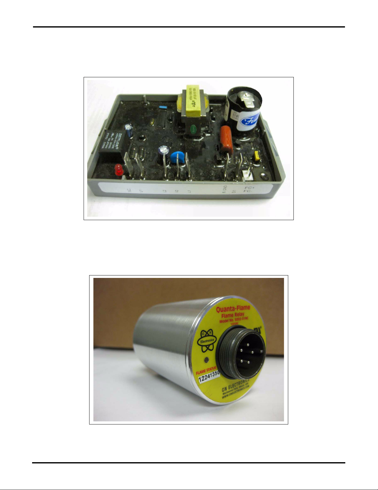
Figure 2 Fenwal Flame Control (HF-4624) (HF-4624 not included)
The GSI part # D03-1168 UV flame relay sensor (See Figure 3) is more reliable since it picks up the
UV light (in the 180-230 nm) that is naturally emitted in the flame when using LP, natural gas or propane
as its fuel. It replaces the flame rod or probe located in the burner and re-produces the expected flame
signal to the fenwal board.
Figure 3 UV Flame Sensor Relay (D03-1168)
This kit will include all the parts necessary to change the flame rectification sensing on a fan/heater used
on portable dryers over to UV style flame sense.
Page 2 of 9 PNEG-1928
Page 3
UV Sensor Retrofit Instruction Manual for Portable Dryers
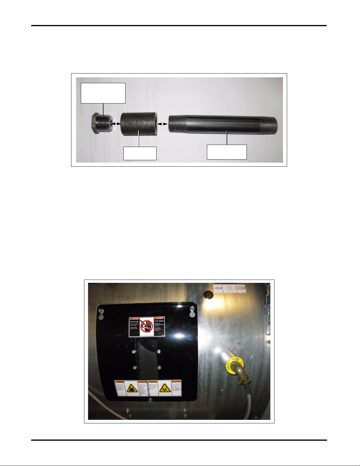
1/2" to 1/8"
Reducer bushing
(007-1149-9)
1/2" x 5" Nipple
(THH-4129)
1/2" Coupler
(D67-0005)
Sight Tube Assembly Instructions
Locate 1/2" x 5" nipple (THH-4129) and attach the 1/2" coupler (D67-0005) to one end of this nipple.
Then attach the 1/2" to 1/8" reducer bushing (007-1149-9) into the 1/2" coupling as shown in Figure 4.
(No sealant is necessary.)
Figure 4 Sight Tube Assembly
Sensor Mounting
The location to mount the sensor is critical in providing reliable flame sense. The sensor needs to
have a constant view to the flame of the burner during all burner modes and operations. Typically the
best location is just to the right of the inspection window plate as shown in Figure 5. The sensor tube
needs to be pointing between the burner veins as shown in Figure 6 on Page 4. It is best if the
sensor points slightly downward to allow any moisture that may be present to drain away from the
UV sensor component.
Once you have determined the sensors location drill a 7/8" hole into the side of the can and attach the
UV sight tube assembly into the hole using two (2) 1/2" lock nuts included with kit. Be sure to leave plenty
of thread sticking through the burner can to mount the UV sensor.
PNEG-1928 Page 3 of 9
Figure 5 Outside Sensor Location
Page 4

UV Sensor Retrofit Instruction Manual for Portable Dryers
Figure 6 Sensor Location Pointing between Burner Veins
Once UV sensor has been mounted to sight tube then attach the five (5) pin cable to sensor. Route the
cable through the black plastic heyco cord connector (FH-1310) then through either an existing hole in the
fan/heater control box or drill a new 7/8" hole. Try to keep the cable entrance location close to the relay
and fenwal board.
Find a location to mount the 3" aluminum din rail and relay base inside the fan/heater control box.
Drill two (2) 9/64" holes that will be used to mount the din rail to the heater back panel. Use the two (2)
supplied self-tapping phillip screws (S-2786) in the drilled holes to mount the din rail. Once the din rail is
secure snap the relay base to the din rail as shown in Figure 7.
Figure 7 Relay Base
Page 4 of 9 PNEG-1928
Page 5

UV Sensor Retrofit Instruction Manual for Portable Dryers
Disconnect power and lock out prior to performing this service.
DANGER
Wiring Instructions
The factory and the UV wirings diagram are included (Figure 9 on Page 6 and Figure 12 on Page 8) which
will help show the difference between the current and modified versions.
1. Cut the supplied red wire into two (2) equal pieces. Strip the insulation off both ends of each wire.
Attach one wire between terminals 10 and 11. Attach the other wire between terminals 5 and 6.
2. Locate the V1 wire on the fenwal board as shown in Figure 8. Leave the wire connected to the
fenwal board and follow it to the terminal strip. Disconnect the wire which will be in terminal
number 21 on the terminal strip.
Figure 8 Locating the V1 grey wire on the fenwal board and terminal 21.
3. Re-locate the grey wire to the relay base terminal 11 which will also contain a jumper wire between
terminals 10 and 11.
4. Strip the insulation off both ends of the supplied grey wire. Attach one end of the grey wire to the
terminal number 21 on the terminal strip (where you removed the grey wire above) and attach the
other end to the relay base terminal 9.
PNEG-1928 Page 5 of 9
Page 6

UV Sensor Retrofit Instruction Manual for Portable Dryers
J5-04 12 VDC Positive
J5-03 12 VDC Negative
J5-02 4-20ma In
J5-01 4-20ma Return
120 VAC Input Power
120 VAC Neutral
12 Volt DC Negative for Testing
12 Volt DC to Housing High-Limit
Housing High-Limit 12 Volt DC Return
12 Volt DC to Vapor High-Limit
Vapor High-Limit 12 Volt DC Return
12 Volt DC for Plenum High-Limit
Plenum High-Limit 12 Volt DC Return
Right Grain High-Limit Yellow
Right Grain High-Limit Yellow
Left Grain High-Limit Orange
Left Grain High-Limit Orange
12 Volt DC to Mercoid (CGA Only)
Mercoid 12 Volt DC Return
12 Volt DC to Air Switch
Air Switch 12 Volt Return
Grain Temp Sensor Input
Temperature Sensor Ground
Temperature Sensor Ground
Plenum Temp Sensor Input
Jumper
21 22 23 24
LOCATE V1 WIRE ON FENWAL, DISCONNECT OTHER
END OF WIRE FROM TERMINAL STRIP #21 LEAVE OTHER
WIRE INTACT THAT RUNS TO J1-01.
GREY WIRE
LEAVE THIS WIRE INTACT
12
345678910111213141516 17181920
FENWAL
LIGHT
N.C.
V1
L2 V2
L1
B.GROUND
S1
FC +
FC -
FLAME
PROBE
PINK
BROWN
RED
GREEN
BLUE
WHITE/BLACK STRIPE
GREY
WHITE
BLACK
ORANGE
YELLOW
PURPLE
REMOVE FLAME PROBE
WIRE FROM S1 (NO
LONGER USED)
COLOR LEGEND
J1-04 120 VAC Neutral
J1-03 120 VAC Input
J1-02 Cycle Solenoid Power
J1-01 Fenwal Terminal V1
J2-05 Fan Power
J2-04 AC Neutral
J2-03 Burner (L1) Power
J2-02 Relay N.O.
J2-01 Relay Com
J3-04 SENSOR GROUND
J3-03 GRAIN SENSOR
J3-02 SENSOR GROUND
J3-01 PLENUM SENSOR
J4-01 12 VDC Positive
J4-02 Extra #1
J4-03 Extra #2
J4-04 Air Switch
J4-05 Mercoid
J4-06 Grain High-Limit
J4-07 Plenum High-Limit
J4-08 Vapor High-Limit
J4-09 Housing High-Limit
J4-10 Fan Overload
Figure 9 Wires to be Moved in Stock Fan/Heater Box (Original Wiring)
Page 6 of 9 PNEG-1928
Page 7

UV Sensor Retrofit Instruction Manual for Portable Dryers
Relay terminals:
1 = No Connection
2 = AC Neutral for Relay
3 = No Connection
4 = No Connection
5 = Jumper to 6
6 = Jumper to 5
7 = No Connection
8 = No Connection
9 = To Main Solenoids and V1 Input on Heater
Figure 10 Flame Sensor Wire Location
5. Disconnect the flame probe or sensor wire from terminal S1 which is shown in Figure 10. It is the
thin red 18 gauge high temperature wire (Teflon) and tie it back out of the way. Attach the red wire
from the UV sensor cable with the spade terminal attached to the S1 terminal of the fenwal. (You
may need to peel back more of the grey sheathing of the UV cable to gain more length of the
wire conductors to reach all the connection points.)
10. Insert time delay relay into its socket and set the timer using the settings as shown in Figure 11.
6. Strip the insulation off both ends of the supplied white wire and insert one end into either terminal
22 or 24 (whichever of the white terminals that contains a single wire) and the other end into
terminal 2 of the relay base.
7. Attach the black wire from the UV sensor cable into terminal 2 of the relay base. This will provide
the grounding path to the flame signal through neutral.
8. Attach the yellow wire from the UV sensor cable into terminal 1 (black terminal) of the terminal strip
in the fan/heater box.
9. Attach the orange wire from the UV sensor cable into terminal 2 (white terminal) of the terminal strip
in the fan/heater box.
PNEG-1928 Page 7 of 9
Figure 11 Timer Settings and Connections
Page 8

UV Sensor Retrofit Instruction Manual for Portable Dryers
1
2
3
4
567
8
9
10
11
ORANGE
YELLOW
BLACK
BROWN
RED
ABCDE
AC Neutral
120 VAC
COM SWITCH
NOT Used
RECTIFIED OUTPUT
Quanta-Flame
UV Scanner System
Series 5002-01NC
FENWAL
LIGHT
N.C.
V1 L2
L1
V2
B.GROUND
S1
FC +
FC -
PINK
BROWN
RED
GREEN
BLUE
WHITE/BLACK STRIPE
GREY
WHITE
BLACK
ORANGE
YELLOW
PURPLE
COLOR LEGEND
TDRSRXP-120V
TIMER SETTINGS
DIP SWITCH FOUR = ON
TURN DIAL TO MAXIMUM (10)
TIME DELAY RELAY = GT3-1182
RELAY BASE = GT3-1181
UV SENSOR = D03-1168
TIMER WILL SHUT OFF
UV SENSOR EVERY 10 HOURS.
DIP SWITCH ONE = ON
DIP SWITCH TWO = ON
DIP SWITCH THREE = ON
120 VAC Input Power
120 VAC Neutral
12 Volt DC Negative for Testing
12 Volt DC to Housing High-Limit
Housing High-Limit 12 Volt DC Return
12 Volt DC to Vapor High-Limit
Vapor High-Limit 12 Volt DC Return
12 Volt DC for Plenum High-Limit
Plenum High-Limit 12 Volt DC Return
Right Grain High-Limit Yellow
Right Grain High-Limit Yellow
Left Grain High-Limit Orange
Left Grain High-Limit Orange
12 Volt DC to Mercoid (CGA Only)
Mercoid 12 Volt DC Return
12 Volt DC to Air Switch
Air Switch 12 Volt Return
Grain Temp Sensor Input
Temperature Sensor Ground
Temperature Sensor Ground
Plenum Temp Sensor Input
Jumper
12
345 6789
10 11 12 13 14 1516
1718 1920
21 22 23 24
Main Solenoid (V1)
Main Sol Neutral
Cycle Sol Neutral
Cycle Solenoid
J5-04 12 VDC Positive
J5-03 12 VDC Negative
J5-02 4-20ma In
J5-01 4-20ma Return
J1-04 120 VAC Neutral
J1-03 120 VAC Input
J1-02 Cycle Solenoid Power
J1-01 Fenwal Terminal V1
J2-05 Fan Power
J2-04 AC Neutral
J2-03 Burner (L1) Power
J2-02 Relay N.O.
J2-01 Relay Com
J3-04 SENSOR GROUND
J3-03 GRAIN SENSOR
J3-02 SENSOR GROUND
J3-01 PLENUM SENSOR
J4-01 12 VDC Positive
J4-02 Extra #1
J4-03 Extra #2
J4-04 Air Switch
J4-05 Mercoid
J4-06 Grain High-Limit
J4-07 Plenum High-Limit
J4-08 Vapor High-Limit
J4-09 Housing High-Limit
J4-10 Fan Overload
Page 8 of 9 PNEG-1928
Figure 12 UV Sensor and Relay Wiring
Page 9

UV Sensor Retrofit Instruction Manual for Portable Dryers
Operation
The UV sensor is highly sensitive to only UVC light that is present in flame. It can detect a small flame
from a lit match over 6' away. Because the particular wavelength “C” band of UV light this sensor is
sensitive to (180-230 nm) is normally absorbed by the ozone present in our atmosphere the sensor will
not be affected by normal sunlight.
The UV Sensor is powered up whenever the dryer controls are energized (orange and yellow wires). The
rectified output (black and red wires) of the UV flame sensor is only active when the sensor senses flame
through an internal relay. This is provided to the fenwal flame board between terminal S1 and the burner
ground or AC Neutral.
The Time delay relay provides a means of self checking to test whether or not the sensor has possibly
burned in a flame sense state. Or in other words the sensor has locked itself up by sensing UV flame
even when flame is not present. So every ten (10) hours the timer will open up the internal contacts that
provide the flame signal to the Vision Flame board J1-01. This interruption will force the controls to cycle
power to the fenwal board in an attempt to relight the burner.
Normally, if the UV sensor stops sensing flame then the fenwal will resume by relighting the burner. This
will cause a brief interruption in burner flame which will last for about five (5) seconds or so until the next
timer relay cycle (ten (10) hours).
If the UV sensor has burned in and continues to sense flame even with no flame present then the fenwal
board will go into a fault condition and will not allow the burner to relight. If the fenwal has a fault condition
then the LED will repeatedly flash two (2) times then pause then flash two (2) times again until power is
lost to the fenwal or the controls system shuts down with an error. This will occur after three (3) failed
relight attempts to the burner.
Life expectancy of the UV sensor is rated for approximately 10000 hours of continuous operation which
should provide many years of reliable use.
Testing
The sensor contains two (2) red LED lamps that will aid in troubleshooting flame sensing issues. One is
labeled “FLAME STATUS” and the other “FLAME RELAY”.
FLAME STATUS indicates the strength of the flame signal. The brighter the LED, the stronger the
flames signal.
FLAME RELAY turns on once the FLAME STATUS becomes strong enough. This is what activates the
flame rectification circuit going to the fenwal board used in the Vision control system.
If the sight tube is positioned too close to the spark or the reducing bushing is not used then the flame
sensor will falsely sense flame and activate the flame relay. This can be tested by dry firing the burner
with the gas turned OFF. You may rarely see the FLAME STATUS light flicker briefly during this test but
it should never be strong enough for the flame relay to become active.
If everything is working correctly the burner should attempt to relight three (3) times then controls will shut
the system down with an ignition failure warning on the screen.
NOTE: The ignition source (spark) is very rich in Ultraviolet light. This can cause the UV sensor to sense
flame if it can see the light that is emitted from the spark. This is the reason we choked the sight
tube down to a 1/8" NPT opening is to reduce this effect.
Do not reverse the Yellow and Orange wires on the UV sensor
The sensor is polarity sensitive and reversing these wires can destroy the sensor.
PNEG-1928 Page 9 of 9
when hooking it up to 120 VAC.
 Loading...