

Page 1
Guidelines for Temperature
Cables on 40-Series Bins
PNEG-1924
Version 1.0
Date: 02-18-13
PNEG-1924
Page 2

All information, illustrations, photos, and specifications in this manual are based on the latest
information available at the time of publication. The right is reserved to make changes at any
time without notice.
2 Pneg-1924
Page 3
1 Temperature Cable Guidelines for
40–Series Bins Equipped with the
Z-Tek™™ Roofing System.
Temperature cable brackets are provided by GSI as standard equipment on all 40–Series Bins equipped
with the Z-Tek™ roofing system. GSI supplied temperature cable brackets are the only approved method
for support of any temperature/moisture cables. All temperature cable brackets must be installed at the
specified locations as shown in this document. Any variation from this pattern or cable quantity must be
approved by GSI Engineering.
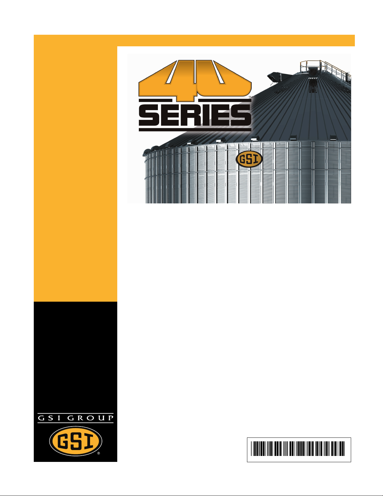
Figure 1-1 Typical Rafter Mounting Using GSI Supplied Temperature Cable Bracket
A Purlin
B Temperature cable bracket
Pneg-1924 3
C Supplier quick link
Page 4
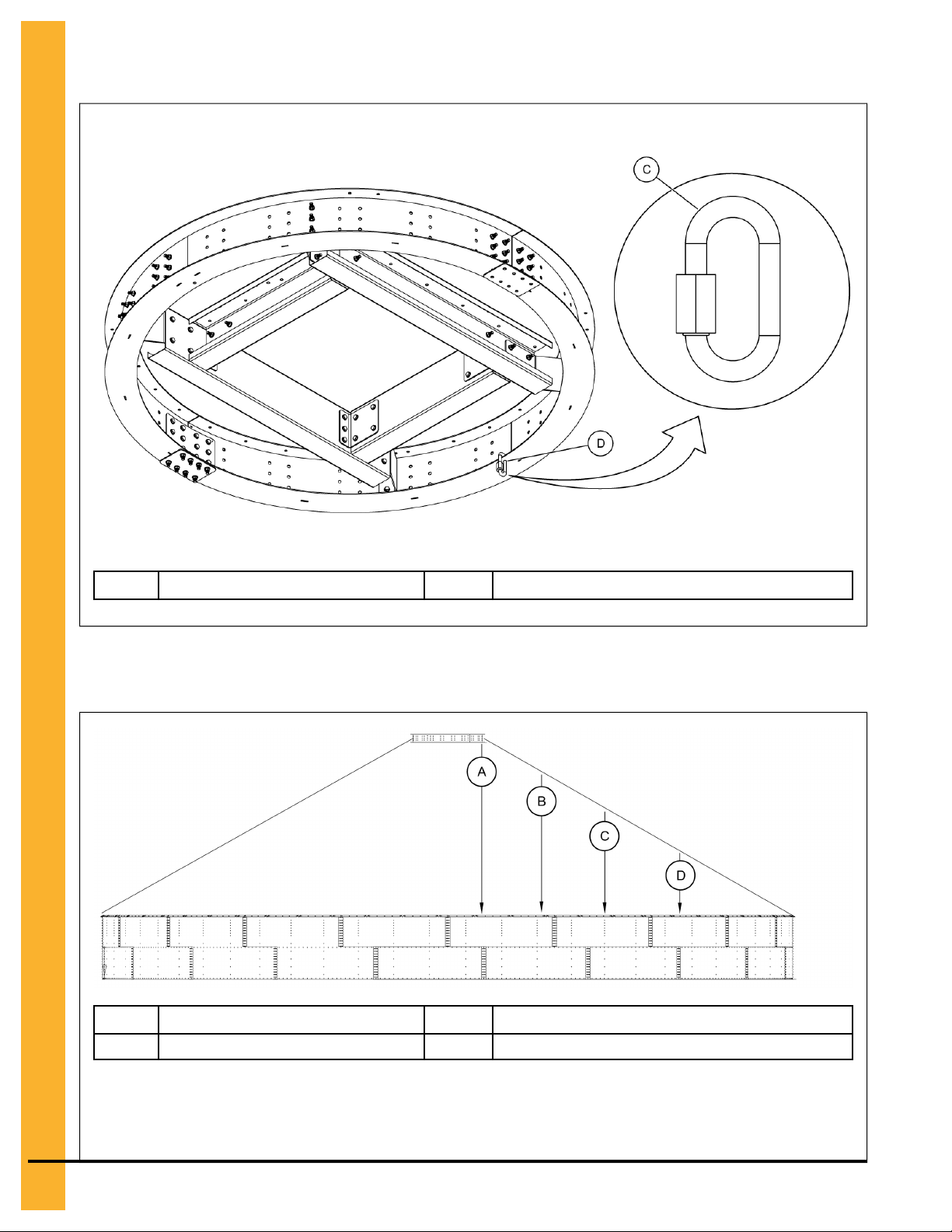
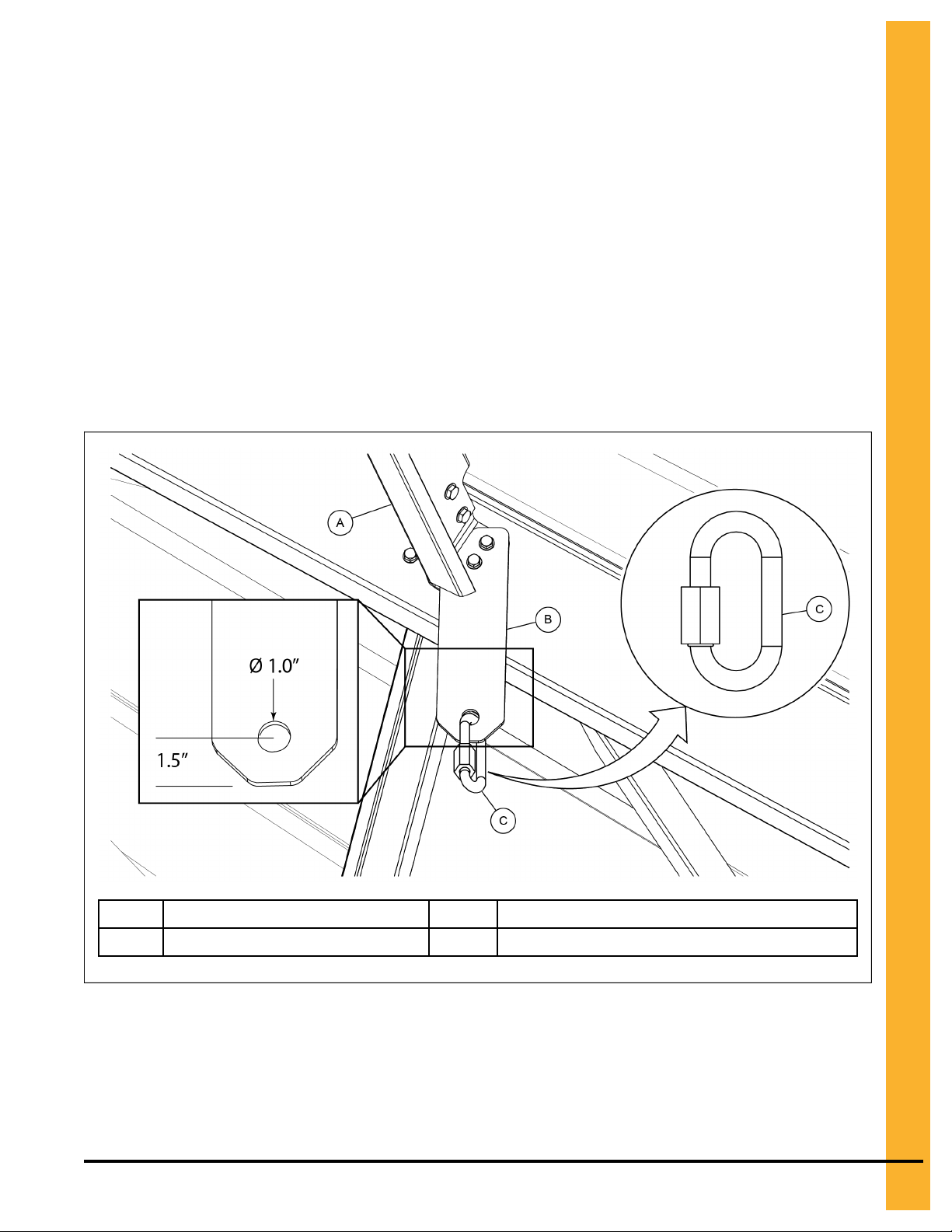
Figure 1-2 Typical Center Collar Installation (Where Applicable)
C Supplier quick link
Figure 1-3 Starting Lengths for Temperature Cables
A
Length from center collar C Rafter radius 2
D
Center collar temperature cable hole
B
Rafter radius 1
D
Rafter radius 3
NOTE: Starting lengths for temperature cables are measured from the temperature cable bracket on
the rafter to the top of the top ring. Temperature cables are located on specific rafter radius
locations and each rafter radius will vary for each bin diameter.
4 Pneg-1924
Page 5

60 ft Diameter Bin
Figure 1-4 A-frame installation sequence and temperature cable locations for 60 ft diameter bin
A
3 ft radius location (center collar)
Table 1-1 Starting lengths for temperature cables for 60 ft diameter bins
Length from the center collar 179.80 in. (45.67 m)
Length from 20 ft diameter location 58.1 in. (14.76 m)
B
20 ft radius location
The temperature cable lengths in the chart above are the distances from where the temperature cable
attaches to the rafter or the center collar to the top ring. To calculate the correct temperature cable length,
add 32 inches for each bin ring to the starting length. Temperature cables must terminate above any
unload equipment and be secured in place with twine. DO NOT allow cables to become tangled in unload
equipment.
Pneg-1924
5
Page 6

72 ft Diameter Bin
Figure 1-5 A-frame installation sequence and temperature cable locations for 72 ft diameter bin
A
9.3 ft radius location
Table 1-2 Starting lengths for temperature cables for 72 ft diameter bins
Length from the center collar
Length from 9.3 ft diameter location 179.2 in. (14.76 m)
Length from 26 ft diameter location 59.6 in. (15.14 m)
B
26 ft radius location
None
The temperature cable lengths in the chart above are the distances from where the temperature cable
attaches to the rafter or the center collar to the top ring. To calculate the correct temperature cable length,
add 32 inches for each bin ring to the starting length. Temperature cables must terminate above any
unload equipment and be secured in place with twine. DO NOT allow cables to become tangled in unload
equipment.
6 Pneg-1924
Page 7

75 ft Diameter Bin
Figure 1-6 A-frame installation sequence and temperature cable locations for 75 ft diameter bin
A
5 ft radius location (center collar) C 26.3 ft radius location
B
11.6 ft radius location
Table 1-3 Starting lengths for temperature cables for 75 ft diameter bins
Length from the center collar 216.1 in. (54.89 m)
Length from 11.6 ft diameter location 148.5 in. (37.72 m)
Length from 26.3 ft diameter location 56.6 in. (14.38 m)
The temperature cable lengths in the chart above are the distances from where the temperature cable
attaches to the rafter or the center collar to the top ring. To calculate the correct temperature cable length,
add 32 inches for each bin ring to the starting length. Temperature cables must terminate above any
unload equipment and be secured in place with twine. DO NOT allow cables to become tangled in unload
equipment.
Pneg-1924
7
Page 8

78 ft Diameter Bin
Figure 1-7 A-frame installation sequence and temperature cable locations for 78 ft diameter bin
A
5 ft radius location (center collar) C 28.6 ft radius location
B
14 ft radius location
Table 1-4 Starting lengths for temperature cables for 78 ft diameter bins
Length from the center collar 226.7 in. (57.58 m)
Length from 14 ft diameter location 166.8 in. (42.37 m)
Length from 28.6 ft diameter location 62.6 in. (15.90 m)
The temperature cable lengths in the chart above are the distances from where the temperature cable
attaches to the rafter or the center collar to the top ring. To calculate the correct temperature cable length,
add 32 inches for each bin ring to the starting length. Temperature cables must terminate above any
unload equipment and be secured in place with twine. DO NOT allow cables to become tangled in unload
equipment.
8 Pneg-1924
Page 9

90 ft Diameter Bin
Figure 1-8 A-frame installation sequence and temperature cable locations for 90 ft diameter bin
A
5 ft radius location (center collar) C 35.5 ft radius location
B
14.8 ft radius location
Table 1-5 Starting lengths for temperature cables for 90 ft diameter bins
Length from the center collar 268.9 in. (68.30 m)
Length from 14.8 ft diameter location 202.1 in. (51.33 m)
Length from 35.5 ft diameter location 55.4 in. (14.07 m)
The temperature cable lengths in the chart above are the distances from where the temperature cable
attaches to the rafter or the center collar to the top ring. To calculate the correct temperature cable length,
add 32 inches for each bin ring to the starting length. Temperature cables must terminate above any
unload equipment and be secured in place with twine. DO NOT allow cables to become tangled in unload
equipment.
Pneg-1924 9
Page 10

105 ft Diameter Bin
Figure 1-9 A-frame installation sequence and temperature cable locations for 105 ft diameter bin
A
5 ft radius location (center collar) C 28.3 ft radius location
B
10.3 ft radius location
Table 1-6 Starting lengths for temperature cables for 105 ft diameter bins
Length from the center collar
Length from 10.3 ft diameter location 288.3 in. (73.22 m)
Length from 28.3 ft diameter location 160.1 in. (40.67 m)
Length from 42.4 ft diameter location 62.5 in. (15.88 m)
D
42.4 ft radius location
None
The temperature cable lengths in the chart above are the distances from where the temperature cable
attaches to the rafter or the center collar to the top ring. To calculate the correct temperature cable length,
add 32 inches for each bin ring to the starting length. Temperature cables must terminate above any
unload equipment and be secured in place with twine. DO NOT allow cables to become tangled in unload
equipment.
10 Pneg-1924
Page 11

135 ft Diameter Bin
Figure 1-10 A-frame installation sequence and temperature cable locations for 135 ft diameter bin
A
12.3 ft radius location C 55.4 ft radius location
B 32.2 ft radius location
Table 1-7 Starting lengths for temperature cables for 135 ft diameter bins
Length from the center collar
Length from 12.3 ft diameter location 318.8 in. (80.98 m)
Length from 32.2 ft diameter location 239.4 in. (60.81 m)
Length from 55.4 ft diameter location 67.9 in. (17.25 m)
None
The temperature cable lengths in the chart above are the distances from where the temperature cable
attaches to the rafter or the center collar to the top ring. To calculate the correct temperature cable length,
add 32 inches for each bin ring to the starting length. Temperature cables must terminate above any
unload equipment and be secured in place with twine. DO NOT allow cables to become tangled in unload
equipment.
Pneg-1924 11
Page 12

NOTES
12 Pneg-1924
Page 13

GSI Group, LLC Limited Warranty
GSI Group, LLC Limited Warranty
The GSI Group, LLC (“GSI”) warrants products which it manufactures to be free of defects in materials and workmanship
under normal usage and conditions for a period of 12 months after sale to the original end-user or if a foreign sale, 14
months from arrival at port of discharge, whichever is earlier. The end-user’s sole remedy (and GSI’s only obligation) is to
repair or replace, at GSI’s option and expense, products that in GSI’s judgment, contain a material defect in materials or
workmanship. Expenses incurred by or on behalf of the end-user without prior written authorization from the GSI Warranty
Group shall be the sole responsibility of the end-user.
Warranty Extensions:
The Limited Warranty period is extended for the following products:
Product Warranty Period
Performer Series Direct Drive Fan Motor 3 Years
AP Fans and Flooring
Cumberland
Feeding/Watering
Systems
Grain Systems Grain Bin Structural Design
Grain Systems
Farm Fans
Zimmerman
All Fiberglass Housings
All Fiberglass Propellers
Feeder System Pan Assemblies
Feed Tubes (1-3/4" and 2.00")
Centerless Augers
Watering Nipples
Portable and Tower Dryers
Portable and Tower Dryer Frames and Internal Infrastructure †
Lifetime
Lifetime
5 Years **
10 Years *
10 Years *
10 Years *
5 Years
2 Years
5 Years
* Warranty prorated from list price:
0 to 3 years - no cost to end-user
3 to 5 years - end-user pays 25%
5 to 7 years - end-user pays 50%
7 to 10 years - end-user pays 75%
** Warranty prorated from list price:
0 to 3 years - no cost to end-user
3 to 5 years - end-user pays 50%
† Motors, burner components and
moving parts not included.
Portable dryer screens included.
Tower dryer screens not included.
GSI further warrants that the portable and tower dryer frame and basket, excluding all auger and auger drive components,
shall be free from defects in materials for a period of time beginning on the twelfth (12
and continuing until the sixtieth (60
th
) month from the date of purchase (extended warranty period). During the extended
th
) month from the date of purchase
warranty period, GSI will replace the frame or basket components that prove to be defective under normal conditions of use
without charge, excluding the labor, transportation, and/or shipping costs incurred in the performance of this extended
warranty.
Conditions and Limitations:
THERE ARE NO WARRANTIES THAT EXTEND BEYOND THE LIMITED WARRANTY DESCRIPTION SET FORTH
ABOVE. SPECIFICALLY, GSI MAKES NO FURTHER WARRANTY OF ANY KIND, EXPRESS OR IMPLIED, INCLUDING,
WITHOUT LIMITATION, WARRANTIES OF MERCHANTABILITY OR FITNESS FOR A PARTICULAR PURPOSE OR
USE IN CONNECTION WITH: (I) PRODUCT MANUFACTURED OR SOLD BY GSI OR (II) ANY ADVICE, INSTRUCTION,
RECOMMENDATION OR SUGGESTION PROVIDED BY AN AGENT, REPRESENTATIVE OR EMPLOYEE OF GSI
REGARDING OR RELATED TO THE CONFIGURATION, INSTALLATION, LAYOUT, SUITABILITY FOR A PARTICULAR
PURPOSE, OR DESIGN OF SUCH PRODUCTS.
GSI shall not be liable for any direct, indirect, incidental or consequential damages, including, without limitation, loss of
anticipated profits or benefits. The sole and exclusive remedy is set forth in the Limited Warranty, which shall not exceed
the amount paid for the product purchased. This warranty is not transferable and applies only to the original end-user. GSI
shall have no obligation or responsibility for any representations or warranties made by or on behalf of any dealer, agent or
distributor.
GSI assumes no responsibility for claims resulting from construction defects or unauthorized modifications to products
which it manufactured. Modifications to products not specifically delineated in the manual accompanying the equipment at
initial sale will void the Limited Warranty.
This Limited Warranty shall not extend to products or parts which have been damaged by negligent use, misuse, alteration,
accident or which have been improperly/inadequately maintained. This Limited Warranty extends solely to products manufactured by GSI.
Prior to installation, the end-user has the responsibility to comply with federal, state and local codes which apply to the location and installation of products manufactured or sold by GSI.
9101239_1_CR_rev7.xml (revised July 2009)
Pneg-1924 13
Page 14

This equipment shall be installed in accordance with the
current installation codes and applicable regulations
which should be carefully followed in all cases.
Authorities having jurisdiction should be consulted
before installations are made.
Copyright © 2013 by GSI Group
Printed in the USA
GSI Group
1004 E. Illinois St.
Assumption, IL 62510-0020
Phone: 1-217-226-4421
Fax: 1-217-226-4420
www.gsiag.com
CN #
 Loading...