

Page 1
PNEG-1914
Single Module Portable Dryer
Parts Manual
PNEG-1914
Date: 04-01-13
Page 2

2 PNEG-1914 Single Module Portable Dryer
Page 3

Table of Contents
Contents
Chapter 1 Main Structure Assembly ....................................................................................................................4
Frame Assembly ....................................... ... .... ... ... ... .......................................... .... ... ... ........................ 4
Frame, Auger Trough, Hopper Bulkheads - 4" Metering Roll ................................................................ 7
Bottom Auger - 4" Metering Rolls ........................................................................................................ 11
Inside (Plenum) Screens, Plenum Closure Doors - 4" Metering Roll .................................................. 13
Outer Screens - 4" Metering Roll Access Doors ................................................................................. 15
Clean Out Doors - 4" Metering Roll ..................................................................................................... 17
Frame and Lower Basket - 7" Metering Roll ....................................................................................... 19
Clean Out Doors - 7" Metering Roll ..................................................................................................... 21
7" Metering Rolls ................................................................................................................................. 25
Bottom Auger - 7" Metering Roll .......................................................................................................... 27
Bottom Auger - Rear Hanger Bearing Assembly ....................................... ... ... ... .... ... ......................... 29
Plenum Screens - 7" Metering Roll ..................................................................................................... 30
Outside Screens - 7" Metering Roll ..................................................................................................... 31
Front and Rear Plenum End Panels ................................................................................................... 33
Plenum Access Door - GSI (D04-0940-Y) .......................................................................................... 35
Plenum Access Door - GSI (D04-0940-F) ........................................................................................... 37
Fan Access Step ................................................................................................................................. 39
Ladder and Fan Assemblies ............................................................................................................... 40
Bottom Auger Discharge Box .............................................................................................................. 41
Top Auger with Wet Bin Assembly ...................................................................................................... 42
Chapter 2 Auger and Metering Roll Drive Trains ..............................................................................................45
4" Bottom Auger Drive ......................................................................................................................... 45
Top Auger Drive .................................................................................................................................. 48
4" Metering Roll Drive ......................................................................................................................... 50
7" Bottom Auger Drive ......................................................................................................................... 52
7" Metering Roll Drive ......................................................................................................................... 54
Chapter 3 Fan/Heaters .........................................................................................................................................57
Fan/Heater Housing Assembly ........ ... ... ... ... .... ... ... ... .......................................... .... ... ... ... ... .... ... ......... 57
Fan Motor, Motor Mount and Fan Blade ............................................................................................. 61
Air Mixer Assemblies ........................................................................................................................... 62
Flame Probe, Ignitor and Burner Assemblies .. ... ... ... .... ... ... ... .... ......................................... .... ... ... ... ... 63
Fan/Heater Assembly ................... .... ... ... ... .......................................... ... .... ... ... ... .... ... ... ...................... 73
LP Pipe Train Assemblies ................................................................................................................... 96
Vaporizer Assembly ......................................................................................................................... . 100
NG Pipe Train Assemblies ............................................................................................................... . 104
LP Supply Line .................................................................................................................................. 107
NG Supply Line ................................................................................................................................. 108
Chapter 4 Dryer Electrical Conduits ................................................................................................................109
Upper Junction Box, Top Auger Motor Conduit and Operator Light ................................... .... ... ... ... . 109
Air Switch Assembly .......................................................................................................................... 110
Right and Left Grain and Plenum High-Limits ................................................................................... 111
Lower Junction Box, Metering Roll Motor Conduit and Rear Discharge Conduit ....................... ... ... . 113
Chapter 5 Control Boxes ...................................................................................................................................115
Fan/Heater Electrical Box ................................................................................ ... .... ... ....................... 115
Control Box Control Panel ............................ .... ... ... ... .... ... ... ... .... ......................................... .. .. ... ... ... . 118
Control Box Switch Panel (Rear) ...................................................................................................... 121
Upper Control Box ............................................................................................................................. 122
Chapter 6 Warranty ............................................................................................................................................145
PNEG-1914 Single Module Portable Dryer 3
Page 4
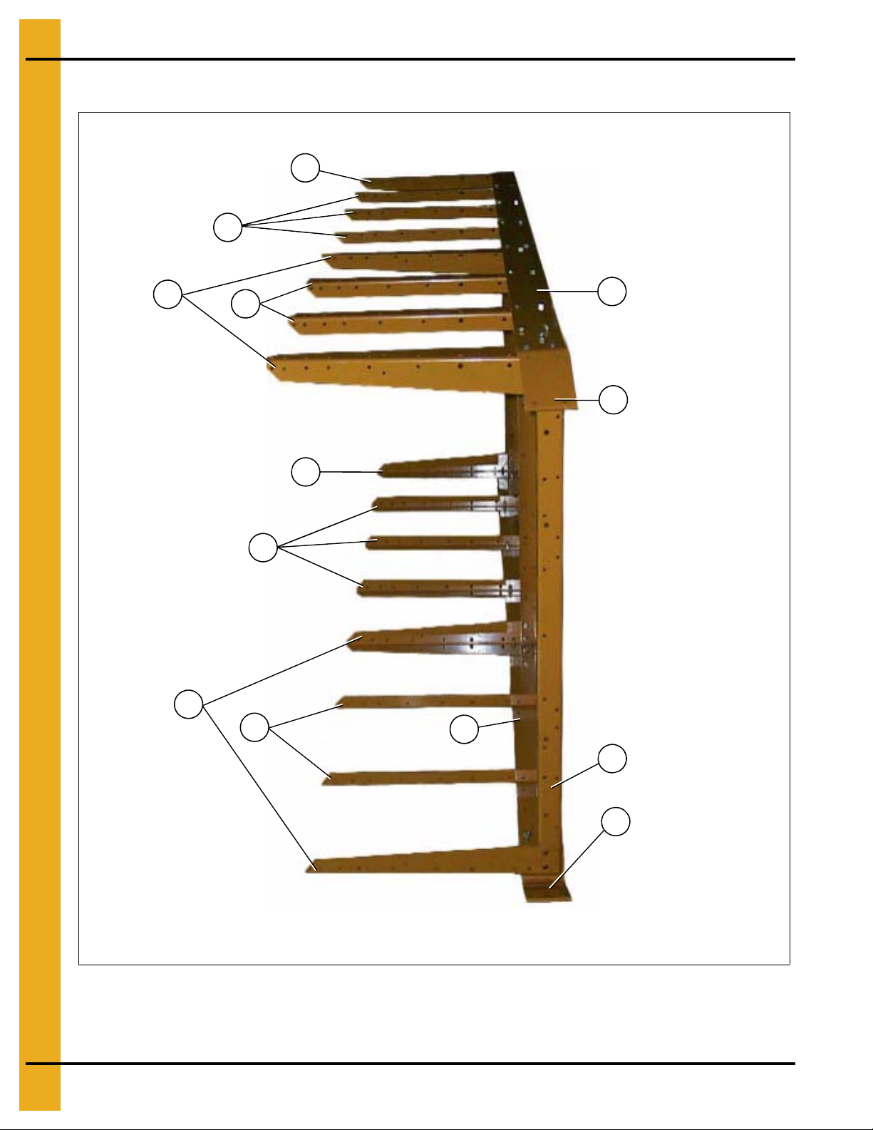
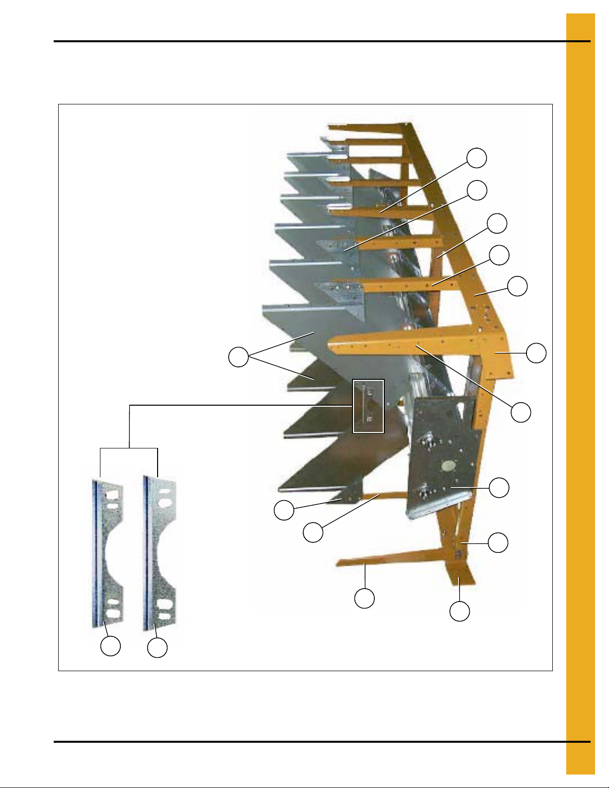
1. Main Structure Assembly
Right side
3
4a
1a
3
2
1
4
5
5
3
5
5
3
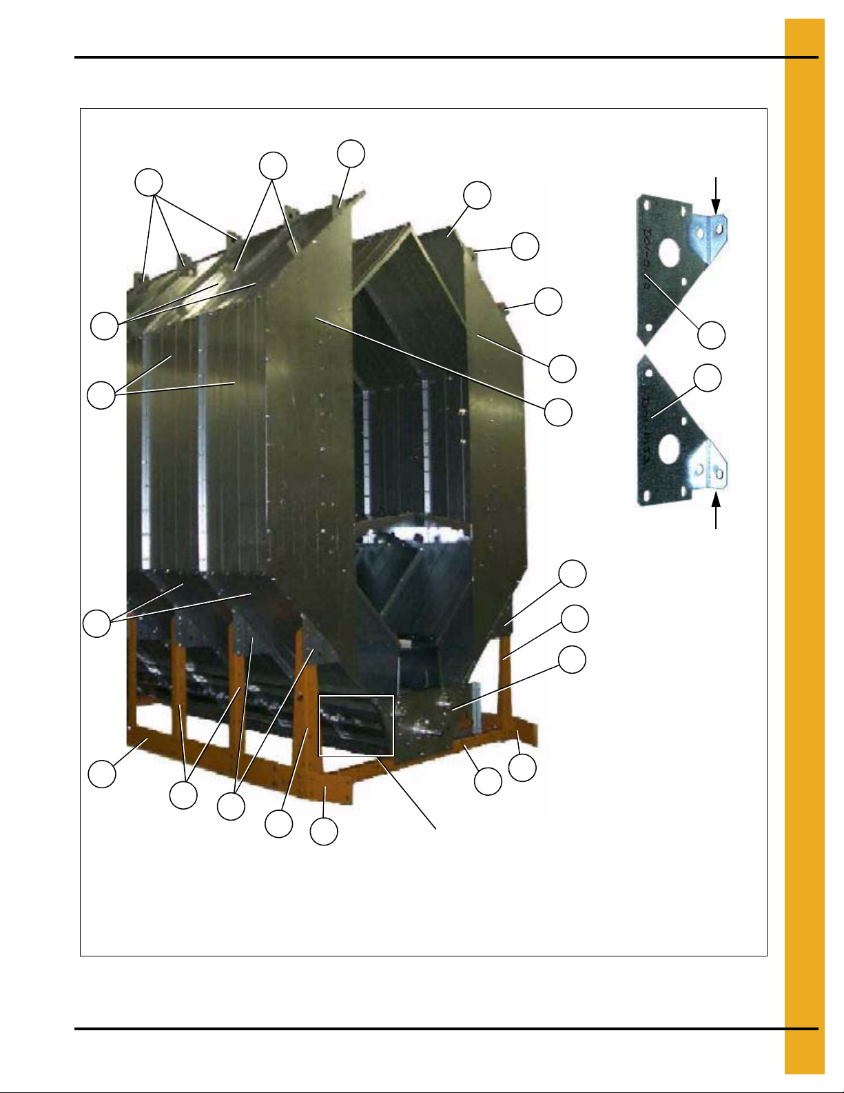
The fan/heater end of the dryer is considered by GSI as the front end of the dryer. (The foreground of
this photograph is the front end. Right and left sides are labeled above.)
Left side
Frame Assembly
Figure 1A Frame Assembly (View from fan/heater end with hitch weldment removed.)
NOTE: The parts pointed out on this page are listed on Page 6.
4 PNEG-1914 Single Module Portable Dryer
Page 5
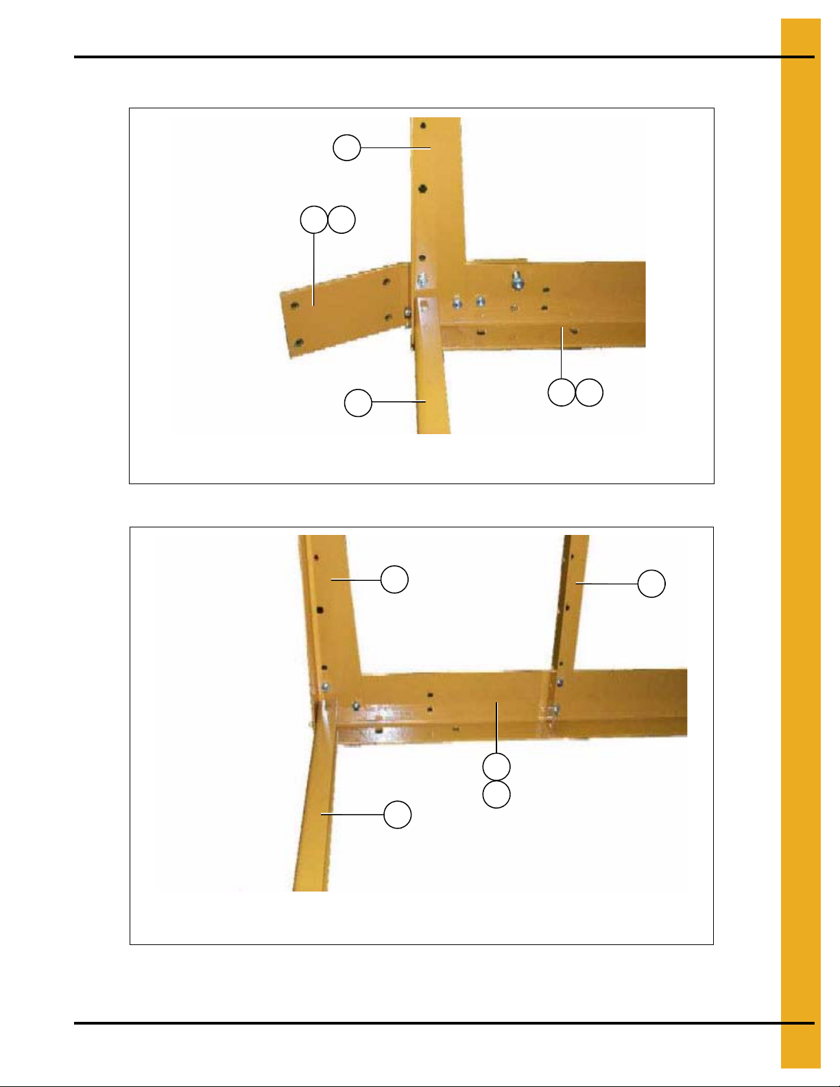
Frame Assembly (Continued)
2
1
1a
NOTE: The right front corner is shown in the photo. For left front corner all parts are the same except for
the hitch bracket (use 1a for the left side), and the frame rail (use 4a for the left side).
4
4a
3
2
5
NOTE: The left rear corner is shown in the photo. For right rear corner all parts are the
same except for the frame rail (use 4 for the right side).
3
4a
4
1. Main Structure Assembly
Figure 1B Right Front Corner of Frame
NOTE: The parts pointed out on this page are listed on Page 6.
PNEG-1914 Single Module Portable Dryer 5
Figure 1C Left Rear Corner of Frame
Page 6
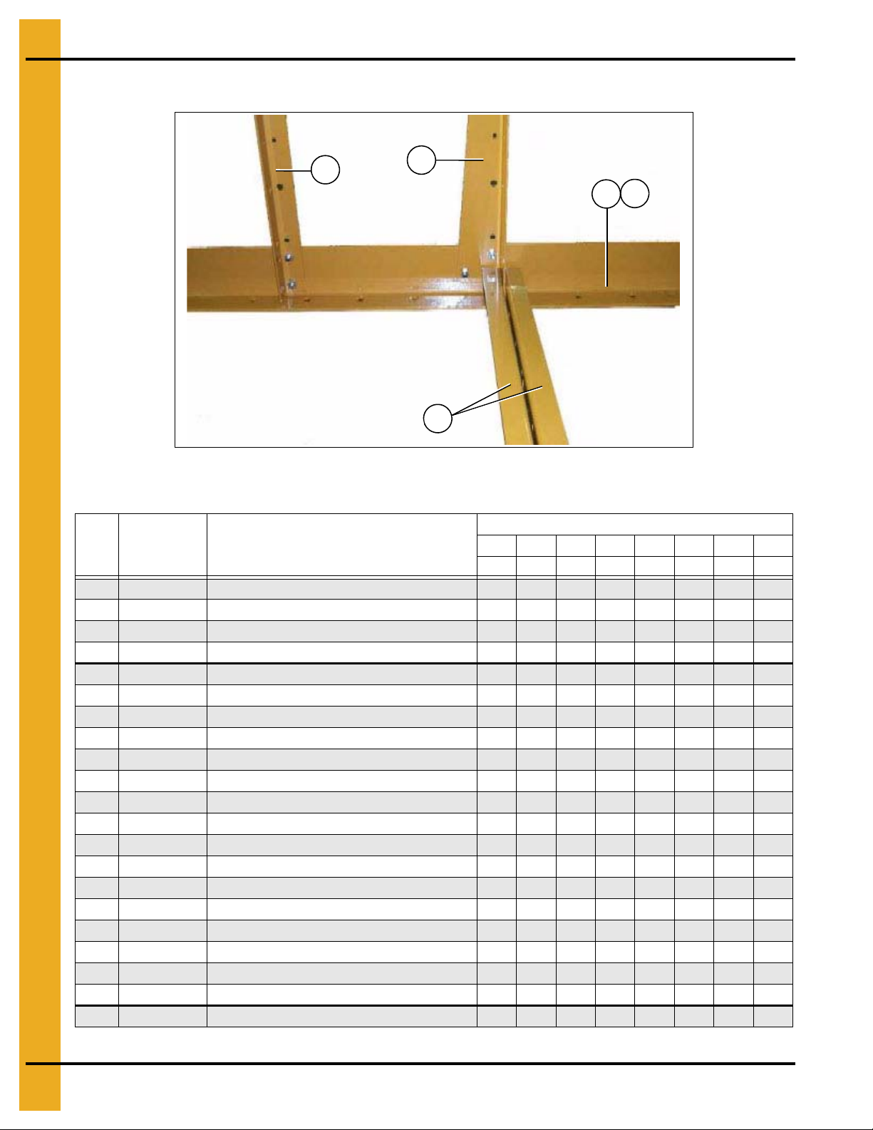
1. Main Structure Assembly
5
3
2
4a
4
Frame Assembly (Continued)
Figure 1D Center Cross Ties
Frame Assembly Parts List
Qty
Ref # Part # Description
1 D01-0012-BK Hitch Bracket - R.H. Black 1 1 1 1 1 1 1 1
1aD01-0011-BKHitch Bracket - L.H. Black 11111111
2 D01-0008-BK Frame Tie Channel - Front, Rear and Center, Black 2 4 4 4 4 4 6 6
3 D01-0007-BK Corner Leg Portable Dryer, Black 4 6 6 6 6 6 8 8
4 D11-0005-BK Frame Rail, 8' R.H. Black 1
4a D11-0004-BK Frame Rail, 8' L.H. Black 1
4 D51-0002-BK Frame Rail, 12' R.H. Black 1
4a D51-0001-BK Frame Rail, 12' L.H. Black 1
4 D21-0011-BK Frame Rail, 14' R.H. Black 1
4a D21-0010-BK Frame Rail, 14' L.H. Black 1
4 D01-0538-BK Frame Rail, 16' R.H. Black 1
4a D01-0537-BK Frame Rail, 16' L.H. Black 1
4 D31-0044-BK Frame Rail, 18' R.H. Black 1
4a D31-0043-BK Frame Rail, 18' L.H. Black 1
4 D61-0002-BK Frame Rail, 20' R.H. Black 1
4a D61-0001-BK Frame Rail, 20' L.H. Black 1
4 D101-0002-BK Frame Rail, 22' R.H. Black 1
4a D101-0001-BK Frame Rail, 22' L.H. Black 1
4 D71-0001-BK Frame Rail, 26' R.H. Black 1
4a D71-0002-BK Frame Rail, 26' L.H. Black 1
5 D01-0005-BK Side Leg Portable Dryer, Black 6 8 10 12 14 16 16 20
1108 1112 1114 1116 1118 1120 1122 1126
D190 D270 D320 D370 D400 D460 D511 D601
6 PNEG-1914 Single Module Portable Dryer
Page 7
1. Main Structure Assembly
2
1
3
6
4
9
5
11
8
6
4
5
6
7
9
10
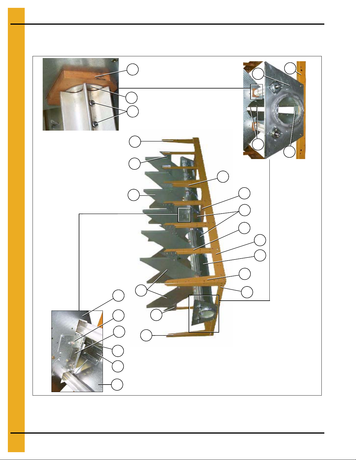
NOTE: The hole pattern of the plenum closure door angles.
This will distinguish between L.H. and R.H.
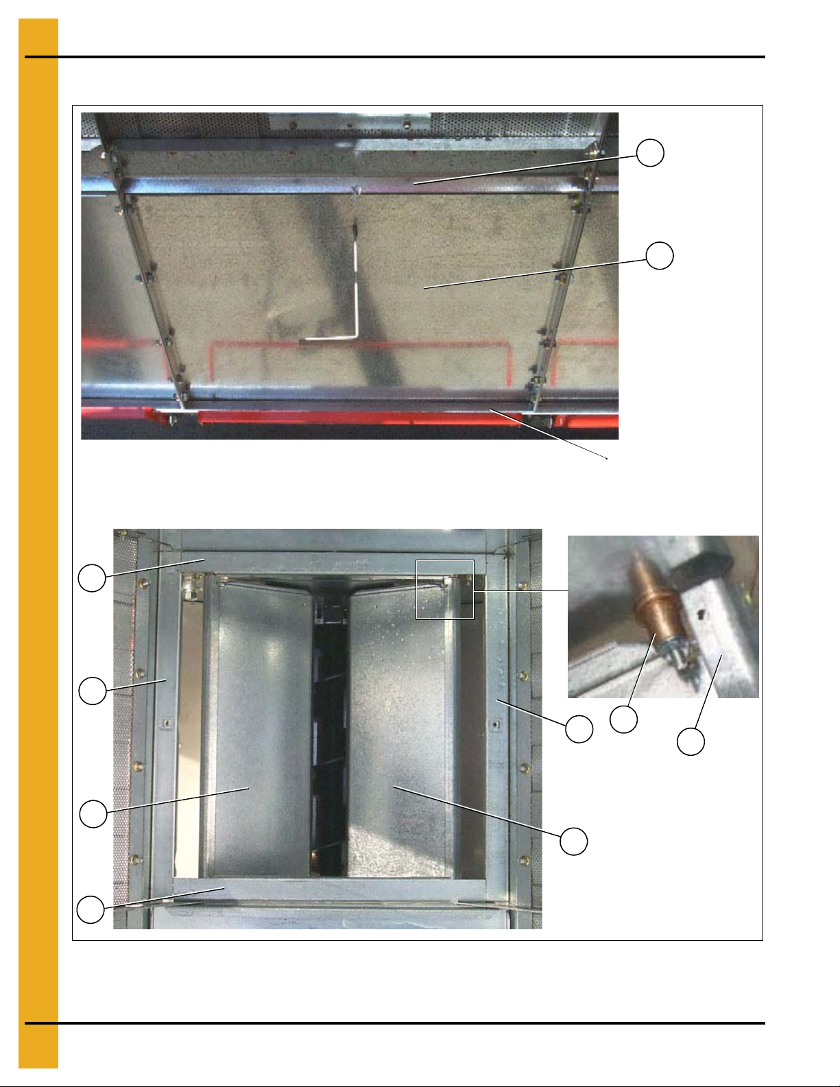
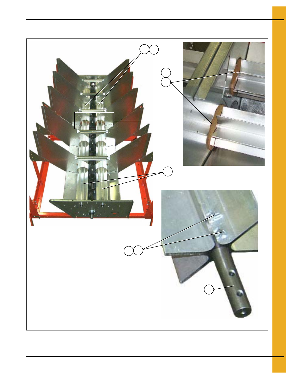
Frame, Auger Trough, Hopper Bulkheads - 4" Metering Roll
Frame, Auger Trough and Hopper Bulkheads
Figure 1E Dryer Frame and Lower Basket Assembly
(View from the front end of the dryer looking down the left side.)
NOTE: The parts pointed out on this page are listed on Page 10.
PNEG-1914 Single Module Portable Dryer 7
Page 8
1. Main Structure Assembly
Wooden metering roll support bearing.
The metering roll sections are spliced
together with a metering roll splice
shaft (part #D31-0046) that passes
through the support bearing assembly.
Center hanger bearing
support and cross
channel seal plate.
20
21
9
6
4
3
6
9
12
5
11a
12
6
9
6
4
3
3
15
14
12
13
19
Discharge bearing plate
12
18
17
16
Frame, Auger Trough, Hopper Bulkheads - 4" Metering Roll
(Continued)
Figure 1F Dryer Frame and Lower Basket Assembly
(View from the rear end of the dryer looking up the ri ght side.)
NOTE: The parts pointed out on this page are listed on Page 10.
8 PNEG-1914 Single Module Portable Dryer
Page 9
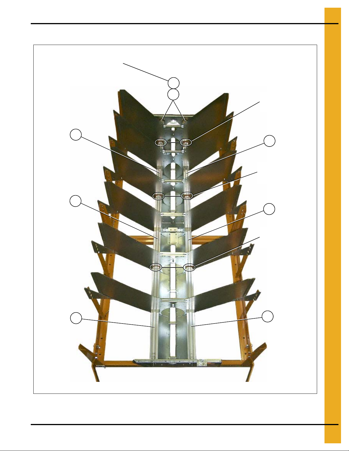
1. Main Structure Assembly
Metering roll bearing
Ref #16, 17 and 18
on Page 10.
This end is the front (fan/heater) end of the dryer.
NOTE: Ref #22 at the rear of dryer is a front section metering roll
that is used as a rear section on 16 and 20 feet dryers only.
22
24
23
23
22
22
23
23
Metering Roll bearing
Ref #16, 17 and 18 on
Page 10.
Metering roll bearing
Ref #16, 17 and 18
on Page 10.
4" Metering Rolls and their Placement in the Dryer
NOTE: The parts pointed out on this page are listed on Page 10.
PNEG-1914 Single Module Portable Dryer 9
Figure 1G
Page 10
1. Main Structure Assembly
Frame, Auger Trough, Hopper Bulkheads - 4" Metering Roll Parts List
Qty
Ref # Part # Description
1 D01-1136Y Plenum Closure Door Angle, R.H. 3 5 6 7 8 9 10 12
2 D01-1136X Plenum Closure Door Angle, L.H. 4 6 7 8 9 10 11 13
3 D01-0109 Hopper Bulkhead 6 10 12 14 16 18 20 24
4 D01-0004 Gusset Plate 10 14 16 18 20 22 24 28
5 D01-0005-BK Side Leg Portable Dryer, Black 6 8 10 12 14 16 16 20
6D01-0007-BKCorner Leg Portable Dryer, Black 46666688
7 D01-0012-BK Hitch Bracket - R.H. Black 1 1 1 1 1 1 1 1
8D01-0011-BKHitch Bracket - L.H. Black 11111111
9 D01-0008-BK Frame Tie Channel - Front, Rear and Center, Black 2 4 4 4 4 4 6 6
10D01-2435 Front Bearing Plate 2008 4" Metering Rolls 11111111
D11-0005-BK Frame Rail, 8' R.H. Black 1
D51-0002-BK Frame Rail, 12' R.H. Black 1
D21-0011-BK Frame Rail, 14' R.H. Black 1
D01-0538-BK Frame Rail, 16' R.H. Black 1
11
D31-0044-BK Frame Rail, 18' R.H. Black 1
D61-0002-BK Frame Rail, 20' R.H. Black 1
D101-0002-BK Frame Rail, 22' R.H. Black 1
D71-0001-BK Frame Rail, 26' R.H. Black 1
D11-0004-BK Frame Rail, 8' R.H. Black 1
D51-0001-BK Frame Rail, 12' L.H. Black 1
D21-0010-BK Frame Rail, 14' L.H. Black 1
D01-0537-BK Frame Rail, 16' L.H. Black 1
11a
D31-0043-BK Frame Rail, 18' L.H. Black 1
D61-0001-BK Frame Rail, 20' L.H. Black 1
D101-0001-BK Frame Rail, 22' L.H. Black 1
D71-0002-BK Frame Rail, 26' L.H. Black 1
12 D01-0048 Trough Panel 8 12 14 16 18 20 22 26
13D01-1512 Plate, Cross Channel Seal with Tabs 1111122
14 D01-1291 Hanger Bearing “C” Channel 1 1 1 1 1 2 2
15D01-1290 Hanger Bearing “J” Plate 2222244
16 D02-0028 Clevis Pin 5/16" x 1-3/4" 16 24 32 32 40 40 48 56
17 D31-0148 Metering Roll Washer 8 12 16 16 20 20 24 28
18 D02-0061 Metering Roll Support Bearing 2 4 6 6 8 8 10 12
19 D01-0177 Support Strap 4 6 7 8 9 10 11 13
20 D01-1511 Plate, End Channel Seal with Tab 2 2 2 2 2 2 2 2
21D01-2434 Discharge Plate 2008 4" Metering Roll 11111111
22 D31-0031 Metering Roll, Front 4 4 2 4 2 4 2 2
23D31-0030 Metering Roll, Intermediate 24466810
24 D31-0029 Metering Roll, Rear 2 2 2 2
1108 1112 1114 1116 1118 1120 1122 1126
D190 D270 D320 D370 D400 D460 D511 D601
The part number list above covers all parts pointed out on Pages 7, 8 and 9.
10 PNEG-1914 Single Module Portable Dryer
Page 11
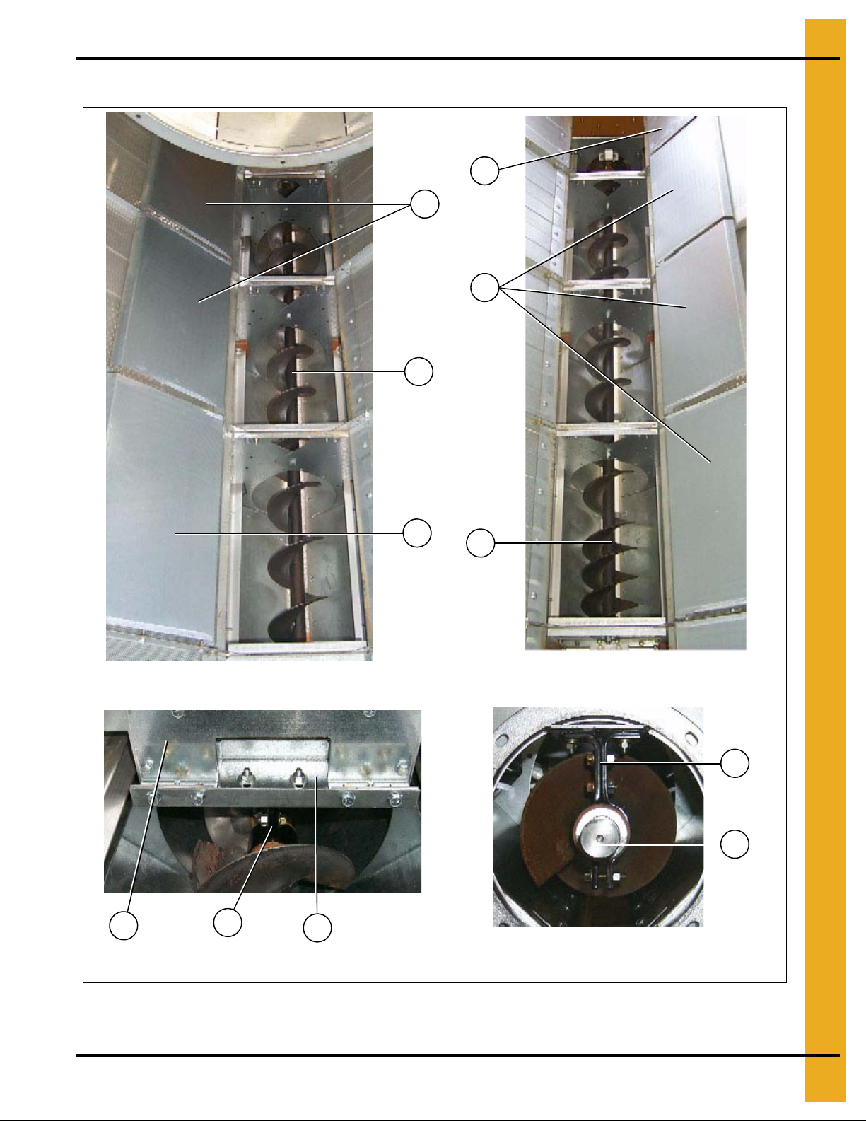
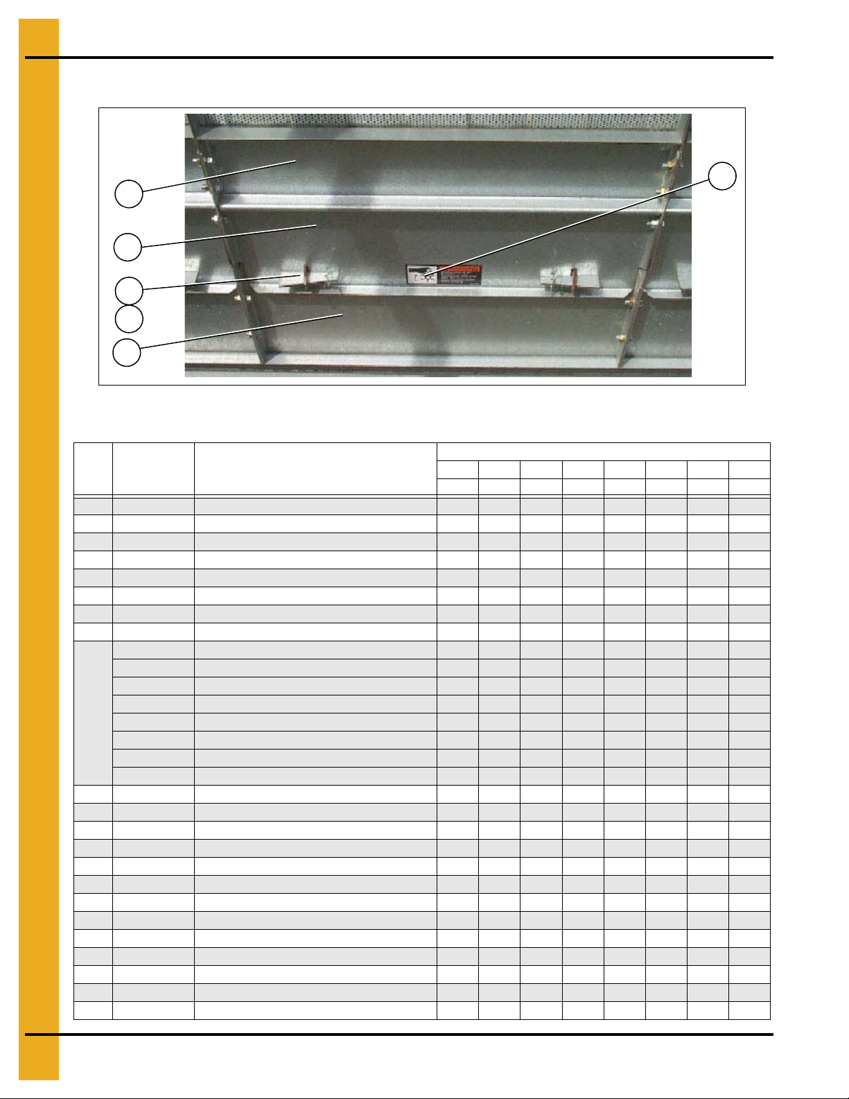
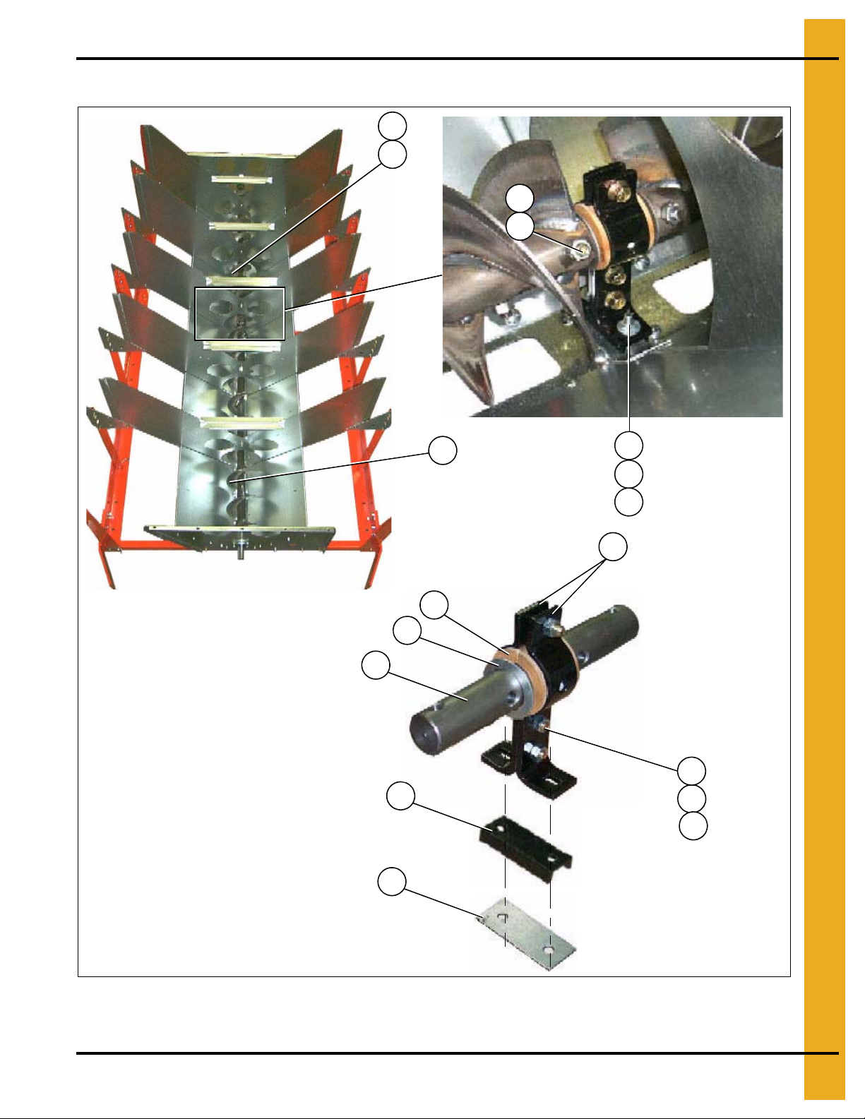
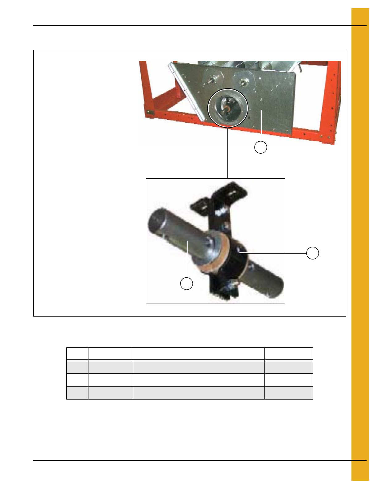
Bottom Auger - 4" Metering Rolls
4" Metering roll bottom auger
Center bearing and support
4" and 7" Metering roll
Bottom auger rear bearing
2
1
5
7
6
4" Metering roll bottom auger
(View from center of dryer to the forward end.)
4" Metering roll bottom auger
(View from center of dryer to the rear end.)
2
3
4
8
7
2
1. Main Structure Assembly
Figure 1H
NOTE: The parts pointed out on this page are listed on Page 12.
PNEG-1914 Single Module Portable Dryer 11
Page 12
1. Main Structure Assembly
Bottom Auger - 4" Metering Rolls Parts List
Qty
Ref # Part # Description
1 D01-1214 Plenum Closure Door, Rear 1 1 1 1 1 1 1 1
2D01-1134Plenum Closure Door 3567891012
D01-1819 Bottom Auger Weldment 8' 1
D21-0017 Auger, Bottom Front Weldment 1 1 1
3
D01-0607 Auger, Bottom Front Weldment 1
D31-0092 Auger, Bottom Front Weldment 1 1
D31-0092 Auger Bottom Front (116-3/8" Long) 1
D01-0801 Auger Top/Bottom Rear Weldment 12' 1
4
D31-0267 Auger, Top and Bottom Weldment 1 1 1 2 2
D61-0184 Auger, Bottom Rear Weldment 1
5 D01-1290 Hanger Bearing “J” Plate 2 2 2 2 2 4 4
6D01-1291Hanger Bearing Bottom “C” Channel 1111122
7 D01-1246 Hanger Bearing “C” Channel 2 2 2 2 2 3 3
8D31-0076Shaft, Auger Splice 2222233
1108 1112 1114 1116 1118 1120 1122 1126
D190 D270 D320 D370 D400 D460 D511 D601
12 PNEG-1914 Single Module Portable Dryer
Page 13
1. Main Structure Assembly
20a
This photograph was taken before the front plenum end panel and
outer screens were installed in order to get a good view of the inside
screens and bulkheads.
Plenum closure door. There are two (2) different plenum closure
doors. The door shown in the photograph is the rear plenum closure
door and is the rear most plenum closure door, Ref #20 (just inside
the rear access door), all others are Ref #20a. NOTE: Ref #22 is the
plenum closure door rear frame angle.
20
21
4
3a
6
7
10
11
13
14
18
12
10
9
15
7
16
1
2
22
5
8
3b
5
19
Inside (Plenum) Screens, Plenum Closure Doors - 4" Metering Roll
Plenum Screens and Bulkheads (View from Front End)
Figure 1I
NOTE: The parts pointed out on this page are listed on Page 14.
PNEG-1914 Single Module Portable Dryer 13
Page 14
1. Main Structure Assembly
16
18
17
19
18
17
19
Upper Shield Assembly - 4" Metering Roll
Figure 1J Close Up of Metering Roll Upper Shield Assembly
Inside (Plenum) Screens, Plenum Closure Doors - 4" Metering Roll Parts List
Ref # Part # Description
1 D31-0055 Column Bulkhead 6 10 12 14 16 18 20 24
2 D01-0101 Garner Bulkhead 6 10 12 14 16 18 20 24
3a D01-2466 Column End Panel - R.H. Front 1 1 1 1 1 1 1 1
3b D01-2467 Column End Panel - L.H. Front 1 1 1 1 1 1 1 1
4 D01-0126 Screen, Plenum Top, GA, 094 8 12 14 16 18 20 22 26
5 D31-0012 Screen, Plenum Wall, GA, 094 8 12 14 16 18 20 22 26
6 D01-1225 Screen, Plenum Bottom, GA, 094 8 12 14 16 18 20 24 26
7 D01-0004 Gusset Plate 10 14 16 18 20 22 24 28
D11-0005-BK Frame Rail, 8' R.H. Black 1
D51-0002-BK Frame Rail, 12' R.H. Black 1
D21-0011-BK Frame Rail, 14' R.H. Black 1
D01-0538-BK Frame Rail, 16' R.H. Black 1
8
D31-0044-BK Frame Rail, 18' R.H. Black 1
D61-0002-BK Frame Rail, 20' R.H. Black 1
D101-0002-BK Frame Rail, 22' R.H. Black 1
D71-0001-BK Frame Rail, 26' R.H. Black 1
D11-0004-BK Frame Rail, 8' L.H. Black 1
D51-0001-BK Frame Rail, 12' L.H. Black 1
D21-0010-BK Frame Rail, 14' L.H. Black 1
D01-0537-BK Frame Rail, 16' L.H. Black 1
9
D31-0043-BK Frame Rail, 18' L.H. Black 1
D61-0001-BK Frame Rail, 20' L.H. Black 1
D101-0001-BK Frame Rail, 22' L.H. Black 1
10 D01-0007-BK Corner Leg Portable Dryer, Black 4 6 6 6 6 6 8 8
11 D01-0012-BK Hitch Bracket - R.H. Black 1 1 1 1 1 1 1 1
12 D01-0011-BK Hitch Bracket - L.H. Black 1 1 4 1 1 1 1 1
13 D01-0008-BK
14 D01-2435 Front Bearing Plate 2008 4" Metering Rolls 1 1 1 1 1 1 1 1
15 D01-0005-BK Side Leg Portable Dryer, Black 6 8 10 12 14 16 16 20
16 D01-0109 Hopper Bulkhead 6 10 12 14 16 18 20 24
17 D01-0050 Connector Sheet 8 12 14 16 18 20 22 26
*18 and 19 D01-1180 Metering Roll Upper Shield Assembly 8 12 14 16 18 20 22 26
18 D01-0431 Metering Roll Strike Off Plate 1/Assembly
19 D01-1226 Metering Roll Shield 1995 Style 1/Assembly
20 D01-1214 Plenum Closure Door, Rear 1 1 1 1 1 1 1 1
20a D01-1134 Plenum Closure Door 4 6 7 8 9 10 12 14
21 DC-974 Danger Foot In Auger Decal 2 2 2 2 2 2 2 2
22 D01-1217 Plenum Closure Door Rear Frame Angle 1 1 1 1 1 1 1 1
*Ref #18 and Ref #19 together make up the metering roll upper shield assembly.
D71-0002-BK Frame Rail, 26' L.H. Black 1
Frame Tie Channel - Front, Rear and
Center, Black
1108 1112 1114 1116 1118 1120 1122 1126
D190 D270 D320 D370 D400 D460 D511 D601
2 4 4 4 4 4 6 6
Qty
14 PNEG-1914 Single Module Portable Dryer
Page 15
Outer Screens - 4" Metering Roll Access Doors
*
*
See Figure 1L on Page 14
*NOTE: Ref #3 is pointing to the top edge angle gusset. There are two (2) types of gusset on the dryer. The photo on top
right will help distinguish the difference between the two. The arrows are pointing to a tab on the gusset that makes them
different (tabs are “bent” up in photo). Ref #3a is used in two (2) places only; 1) front right of dryer 2) rear left of dryer, all
others are Ref #3.
3a
3
4
1a
9
10
14
12
11
10
7
5
4
2
3a
2
3
*
6
3
8
9
13
1b
1. Main Structure Assembly
Figure 1K Outer Screens (View from front end.)
NOTE: The parts pointed out on this page are listed on Page 16.
PNEG-1914 Single Module Portable Dryer 15
Page 16
1. Main Structure Assembly
18
17
19
16
20
15
Outer Screens - 4" Metering Roll Access Doors (Continued)
Figure 1L Metering Roll Access Door
Outer Screens - 4" Metering Roll Access Doors Parts List
Qty
Ref # Part # Description
1a D01-2466 Column End Panel - R.H. Front 1 1 1 1 1 1 1 1
1bD01-2467Column End Panel - L.H. Front 11111111
2 D01-0113 Walk Rail Mounting Bracket 10 16 18 20 22 24 28 32
3 D01-0152 Top Edge Angle Gusset - L.H. 8 12 14 16 18 20 22 26
3a D01-0153 Top Edge Angle Gusset - R.H. 2 2 2 2 2 2 2 2
4 D01-0127 Screen, Roof, GA, 094 8 12 14 16 18 20 22 26
5 D31-0013 Screen, Outside Wall Sheet 8 12 14 16 18 20 22 26
6 D01-0128 Screen, Hopper Sheet 8 12 14 16 18 20 22 26
D11-0005-BK Frame Rail, 8' R.H. Black 1
D51-0002-BK Frame Rail, 12' R.H. Black 1
D21-0011-BK Frame Rail, 14' R.H. Black 1
D01-0538-BK Frame Rail, 16' R.H. Black 1
7
D31-0044-BK Frame Rail, 18' R.H. Black 1
D61-0002-BK Frame Rail, 20' R.H. Black 1
D101-0002-BK Frame Rail, 22' R.H. Black 1
D71-0001-BK Frame Rail, 26' R.H. Black 1
8 D01-0005-BK Side Leg Portable Dryer, Black 6 8 10 12 14 16 16 20
9 D01-0004 Gusset Plate 10 14 16 18 20 22 24 28
10 D01-0007-BK Corner Leg Portable Dryer, Black 4 6 6 6 6 6 8 8
11 D01-0012-BK Hitch Bracket - R.H. Black 1 1 1 1 1 1 1 1
12 D01-0011-BK Hitch Bracket - L.H. Black 1 1 1 1 1 1 1 1
13 D01-0008-BK Frame Tie Channel - Front, Rear and Center, Black 2 4 4 4 4 4 6 6
14 D01-2435 Front Bearing Plate 2008 4" Metering Rolls 1 1 1 1 1 1 1 1
15 D01-0050 Conn ec tor She et 8 12 14 16 18 20 22 26
16 D01-0045 Access Door 8 12 14 16 18 20 22 26
17 D01-0039 Door La tch 16 24 28 32 36 40 44 52
18 S-6552 Pin, Hair Clip 3/32" 16 24 28 32 36 40 44 52
19 DC-1229 Decal, Warning Metering Roll Rot. 8 12 14 16 18 20 22 26
20 D01-0048 Trough Panel Weldment 8 12 14 16 18 20 22 26
1108 1112 1114 1116 1118 1120 1122 1126
D190 D270 D320 D370 D400 D460 D511 D601
16 PNEG-1914 Single Module Portable Dryer
Page 17

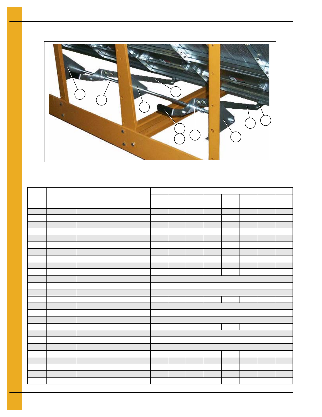
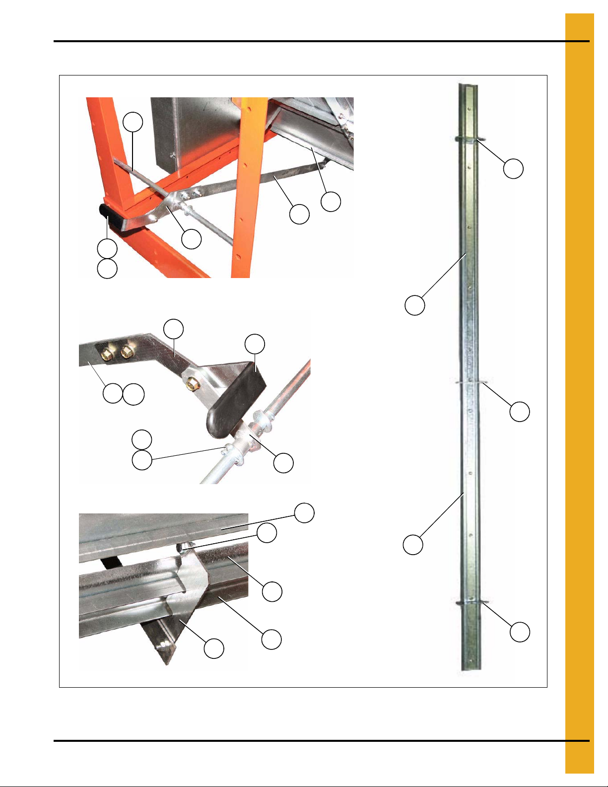
Clean Out Doors - 4" Metering Roll
5
3a
7
NOTE: Ref #9, 10 and 11 together create the clean out
door assembly. There are three (3) different clean out
door assemblies that are used on GSI Network dryers:
1) 3 Column clean out door assembly (D51-0077). Ref #8a
on the part # listing (Page 18).
2) 4 Column clean out door assembly (D11-0032). Ref #8b
on the part # listing (Page 18).
3) 5 Column clean out door assembly (D01-0349). Ref #8c
on the part # listing (Page 18).
A 5 column clean out door assembly (D01-0349) is shown in
the photograph above.
1
4
2
13
3
4
2
6
5
9
10
11
12
13
9
11
11
11
Clean out door hinge
Front and rear handle mechanisms (rear shown in photo)
Clean out door handle mechanism
10
3
1. Main Structure Assembly
NOTE: The parts pointed out on this page are listed on Page 18.
PNEG-1914 Single Module Portable Dryer 17
Figure 1M
Page 18
1. Main Structure Assembly
5
14
1a
14
3a
4
2
14
3a
11
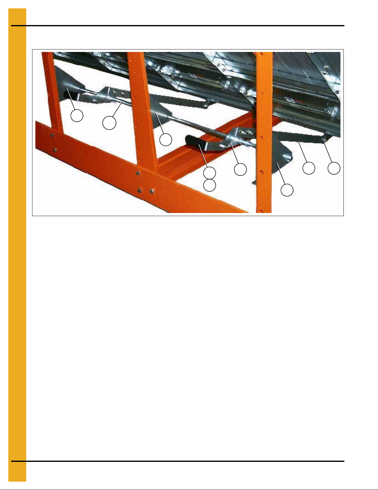
Clean Out Doors - 4" Metering Roll (Continued)
Figure 1N Center Handle Mechanisms (This handle mechanism straddles the center cross chan nels.)
Clean Out Doors - 4" Metering Roll Parts List
Qty
Ref # Part # Description
1 D01-0264 Pivot Rod 25-3/16" 2 2 2 2 2 2 2 2
1aD31-0162Pivot Rod 49-5/8" 1111122
2 D01-0296 Linkage Bar Weldment 2 4 4 4 4 4 6 6
3D01-0261Linkage Bar, 37" Long 22222222
3a D01-0293 Linkage Bar, 30" Long 2 2 2 2 2 4 4
4 D01-0294 Clean Out Door Handle 2 4 4 44466
5 S-4378 Plastic Grip 2 4 4 4 4 4 6 6
6 S-248 Flat Washer 3/8" USS ZN 4 8 8 8 8 8 12 12
7 S-7241 Cotter Pin, 1/8" x 1-1/4" 4 8 8 8 8 8 12 12
8a D51-0077 Clean Out Door Assembly, 3 Column 2 1 1
9 D21-0005 Clean Out Door, 67" 1/Assembly
10 D21-0012 Support Channel, Clean Out Door 1/Assembly
11 D01-0308 Clean Out Door Hinge 2/Assembly
8b D11-0032 Clean Ou t Door Assembly, 4 Column 1 1 2 1 2 2
9 D31-0021 Clean Out Door, 91" 1/Assembly
10 D31-0130 Support Channel, Clean Out Door 1/Assembly
11 D01-0308 Clean Out Door Hinge 2/Assembly
8c D01-0349 Clean Out Door Assembly, 5 Column 1 2 1
9 D01-0180 Clean Out Door, 115" 1/Assembly
10 D01-0307 Support Channel, Clean Out Door 1/Assembly
11 D01-0308 Clean Out Door Hinge 3/Assembly
12 D01-0175 Hinge Bra cket 2 4 4 55667
13 D01-0181 Clean Out Extension, 119-3/4" 2 4 2
13 D31-0023 Clean Out Extension, 90-3/4" 2 2 4 2 4 4
13 D21-0006 Clean Out Extension, 66-3/4" 4 2 2
14D01-0299Pivot Rod Bracket 3333366
18 PNEG-1914 Single Module Portable Dryer
1108 1112 1114 1116 1118 1120 1122 1126
D190 D270 D320 D370 D400 D460 D511 D601
Page 19
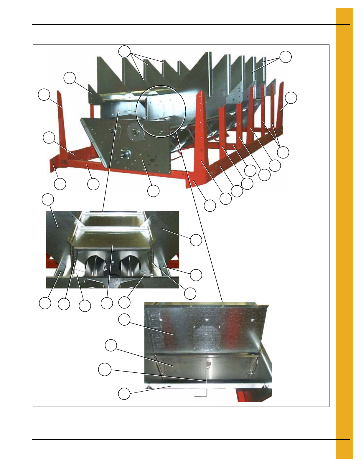
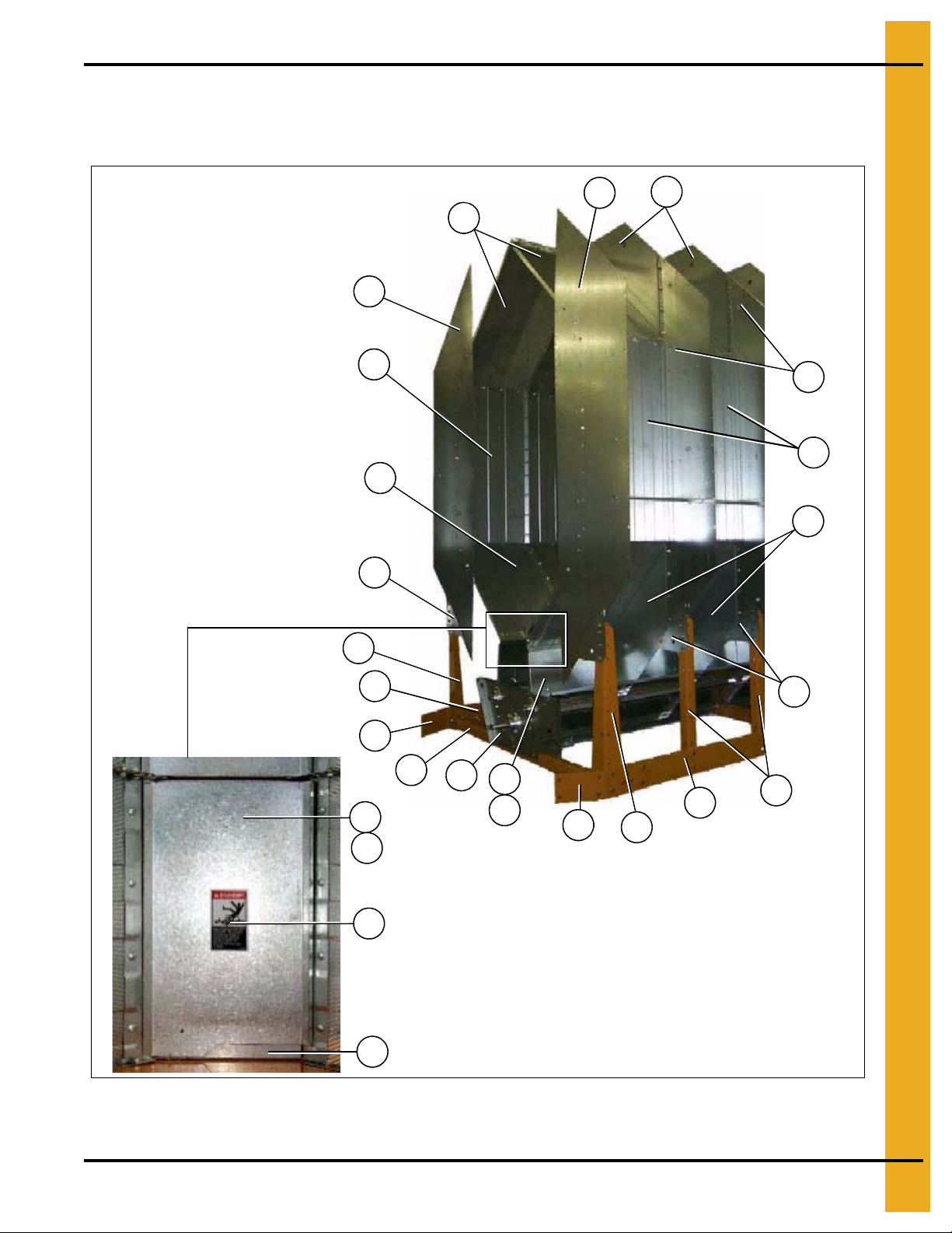
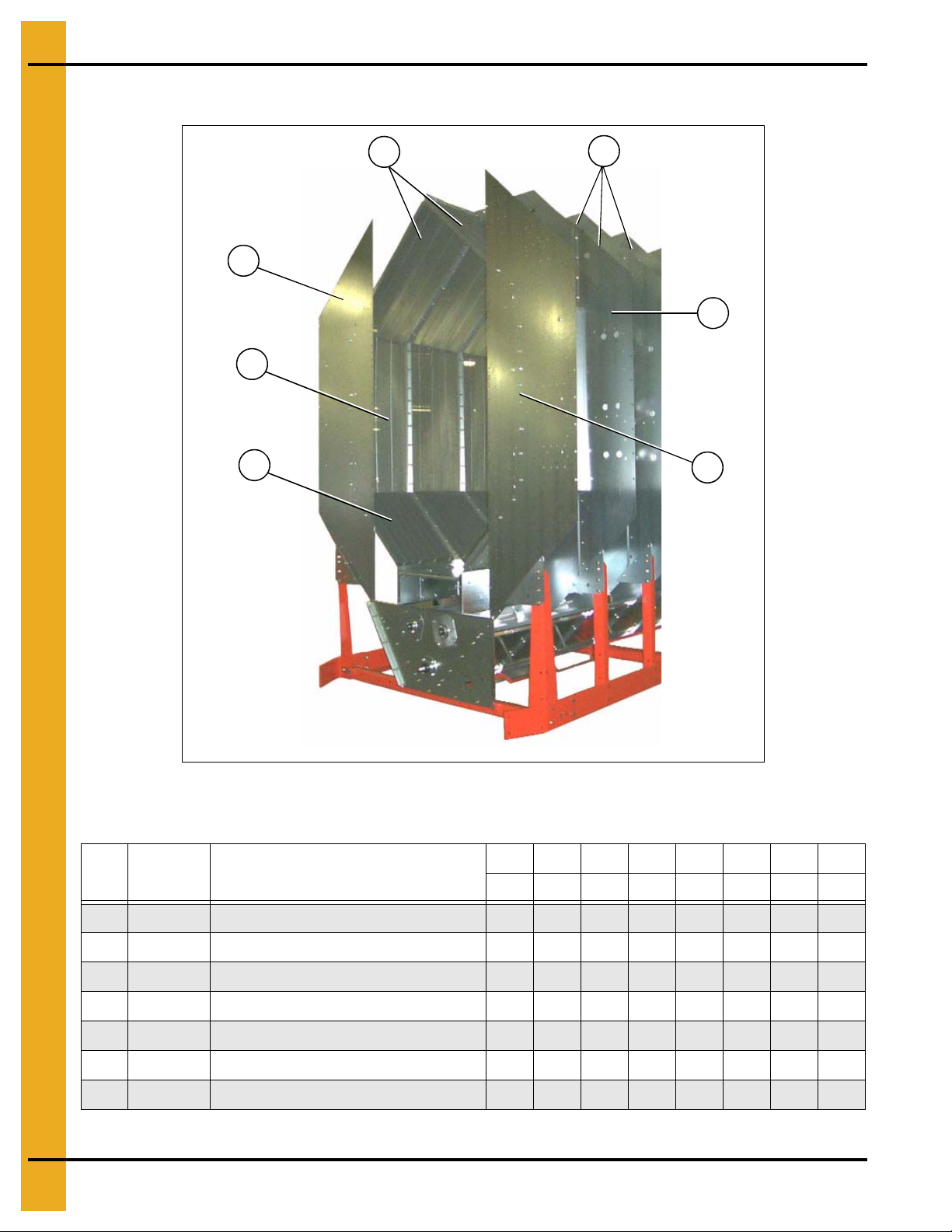
Frame and Lower Basket - 7" Metering Roll
Grain diverter and metering roll pan
assemblies. This photo was taken
before screens were install ed looking
down the inside of the grain column.
Metering roll access doors
1
2
3
4
6
3
4a
9
7
9
3
9
3
1
8
7
5
1
10
11
12
13
12
11
10
1
11
14
14a
10
1. Main Structure Assembly
Figure 1O
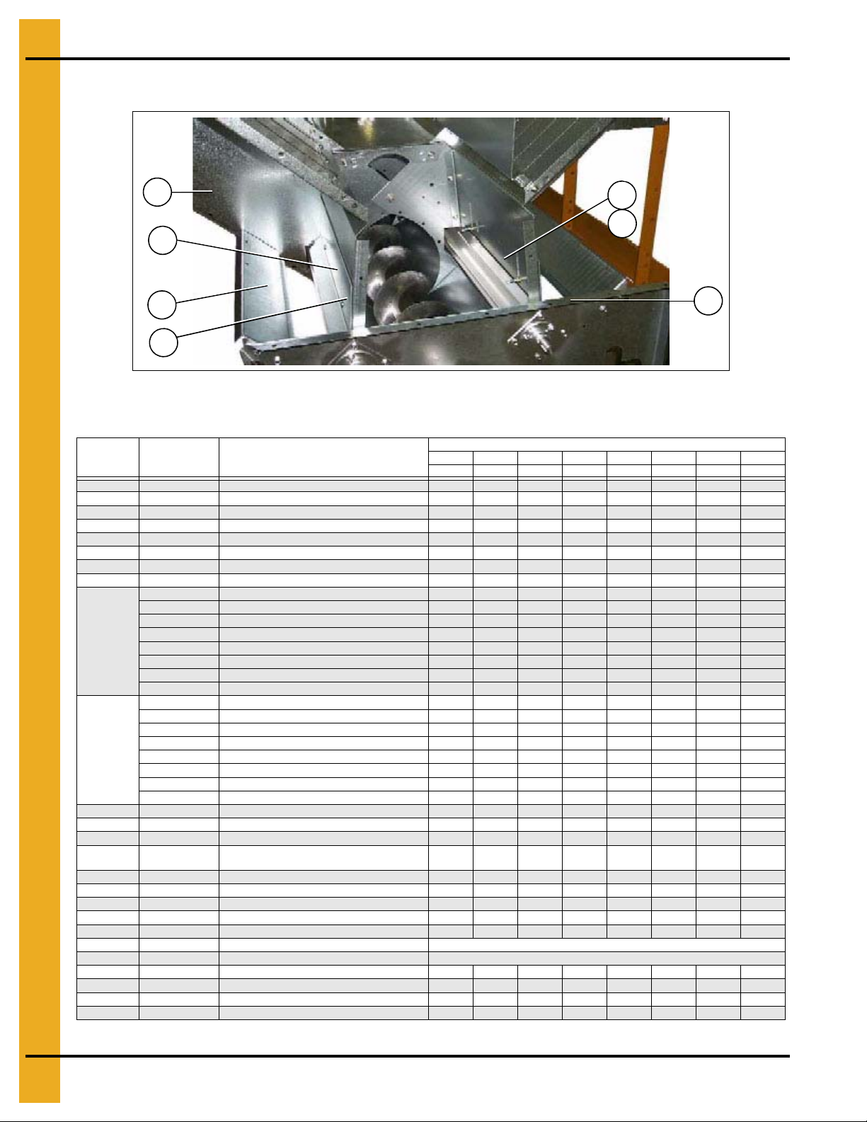
NOTE: The parts pointed out on this page are listed on Page 23 and Page 24.
PNEG-1914 Single Module Portable Dryer 19
Page 20
1. Main Structure Assembly
Clean out door assembly.
(See Page 21.)
Grain flow regulators. This photo was taken with the metering roll access
door (ref #13) removed and looking down at the unload auger.
Auger trough panels
10
15
16
11
12
12
11
17
12
16
Frame and Lower Basket - 7" Metering Roll (Continued)
NOTE: The parts pointed out on this page are listed on Page 23 and Page 24.
Figure 1P
20 PNEG-1914 Single Module Portable Dryer
Page 21
Clean Out Doors - 7" Metering Roll
Front and rear handle mechanisms (rear shown in photo)
Clean out door handle mechanism
Clean out door hinge
20
30
18
21
19
20
20a
21
22
23
24
19
29
26
27
28
28
27
28
26
28
30
22
1. Main Structure Assembly
Figure 1Q
NOTE: The parts pointed out on this page are listed on Page 23 and Page 24.
PNEG-1914 Single Module Portable Dryer 21
Page 22
1. Main Structure Assembly
31
18a
31
28
20a
31
19
21
22
Clean Out Doors - 7" Metering Roll (Continued)
Figure 1R Center Handle Mechanisms (This handle mechanism stradles the center cross channels.)
NOTE: Ref # 26, 27 and 28 together create the clean out door assembly. There are three (3) different
clean out door assemblies that are used on FFI Dri-Tek dryers.
1. 3 Column clean out door assembly (D51-0077). Ref # 25A on the part # listing on Page 24.
2. 4 Column clean out door assembly (D11-0032). Ref # 25B on the part # listing on Page 24.
3. 5 Column clean out door assembly (D01-0349). Ref # 25C on the part # listing on Page 24.
4. 5 Column clean out door assembly (D01-0349) (See Figure 1Q on Page 21.)
NOTE: The parts pointed out on this page are listed on Page 23 and Page 24.
22 PNEG-1914 Single Module Portable Dryer
Page 23

1. Main Structure Assembly
Frame, Lower Basket and Clean Out Doors - 7" Metering Roll Parts List
Ref # Part # Description
1 401-5259-7 Hopper Bulkhead - 7" Metering Roll 6 10 12 14 16 18 20 24
2 D01-0004 Gusset Plate 10 4 6 8 20 22 24 28
3 D01-0007-BK Corner Leg Portable Dryer, Black 4 6 6 6 6 6 8 8
4 D11-0005-BK Frame Rail, 8' R.H. Black 1
4a D11-0004-BK Frame Rail, 8' L.H. Black 1
4 D51-0002-BK Frame Rail, 12' R.H. Black 1
4a D51-0001-BK Frame Rail, 12' L.H. Black 1
4 D21-0011-BK Frame Rail, 14' R.H. Black 1
4a D21-0010-BK Frame Rail, 14' L.H. Black 1
4 D01-0538-BK Frame Rail, 16' R.H. Black 1
4a D01-0537-BK Frame Rail, 16' L.H. Black 1
4 D31-0044-BK Frame Rail, 18' R.H. Black 1
4a D31-0043-BK Frame Rail, 18' L.H. Black 1
4 D61-0002-BK Frame Rail, 20' R.H. Black 1
4a D61-0001-BK Frame Rail, 20' L.H. Black 1
4 D101-0002-BK Frame Rail, 22' R.H. Black 1
4a D101-0001-BK Frame Rail, 22' L.H. Black 1
4 D71-0001-BK Frame Rail, 26' R.H. Black 1
4a D71-0002-BK Frame Rail, 26' L.H. Black 1
5 D01-0012-BK Hitch Bracket - R.H. Black 1 1 1 1 1 1 1 1
6 D01-0011-BK Hitch Bracket - L.H. Black 1 1 1 1 1 1 1 1
7 D01-0008-BK
8 D01-1848-6 Front Bearing Plate 1 1 1 1 1 1 1 1
9 D01-0005-F Side Leg 6 8 10 12 14 16 16 20
10 401-5289-4 Column Stiffener 8 12 14 16 18 20 22 26
11 415-4616-9 Grain Diverter Assembly - 7" Metering Roll 8 12 14 16 18 20 22 2 6
12 401-5293-6 Grain Flow Regulator - 7" Metering Roll 8 12 14 16 18 20 22 26
13 401-5370-2 Access Door - 7" Metering Rolls 4 6 7 8 9 10 11 13
14 415-4604-5 7" Metering Roll Pan Assembly 8 12 14 16 18 20 22 26
14a 406-2450-4 Push Lever Arm 8 12 14 16 18 20 22 26
15 401-5302-5 Auger Trough Panel 8 12 14 16 18 20 22 26
16 401-5303-3 Support Channel for Meter Access Door 8 12 14 16 18 20 22 26
17 017-1552-3 Bearing - Bronze 5/8" O.D. x 1/4" I.D. 16 24 28 32 36 40 44 52
18 D01-0264 Pivot Rod 25-3/16" 2 2 2 2 2 2 2 2
18a D31-0162 Pivot Rod 49-5/8" 1 1 1 1 1 2 2
19 D01-0296 Linkage Bar Weldment 2 4 4 4 4 4 6 6
20 D01-0261 Linkage Bar, 37" Long 2 2 2 2 2 2 2 2
20a D01-0293 Linkage Bar, 30" Long 2 2 2 2 2 4 4
Frame Tie Channel - Front, Rear and
Center, Black
1108 1112 1114 1116 1118 1120 1122 1126
D190 D270 D320 D370 D 400 D460 D511 D601
24444466
PNEG-1914 Single Module Portable Dryer 23
Page 24
1. Main Structure Assembly
Frame, Lower Basket and Clean Out Doors - 7" Metering Roll Parts List (Continued)
1108 1112 1114 1116 1118 1120 1122 1126
Ref # Part # Description
21 D01-0294 Clean Out Door Handle 2 4 4 4 4 4 6 6
22 S-4378 Plastic Grip 2 4 4 4 4 4 6 6
23 S-248 Flat Washer, 3/8" USS ZN 4 8 8 8 8 8 12 12
24 S-7241 Cotter Pin, 1/8" x 1-1/4" 4 8 8 8 8 8 12 12
25a D51-0077 Clean Out Door Assembly, 3 Column 2 1 1
26 D21-0005 Clean Out Door, 67" 1/Assembly
27 D21-0012 Support Channel, Clean Out Door 1/Assembly
28 D01-0308 Clean Out Door Hinge 2/Assembly
25B D11-0032 Clean Out Door Assembly, 4 Column 1 1 2 1 2 2
26 D31-0021 Clean Out Door, 91" 1/Assembly
D190 D270 D320 D370 D400 D460 D511 D601
27 D31-0130 Support Channel, Clean Out Door 1/Assembly
28 D01-0308 Clean Out Door Hinge 2/Assembly
25C D01-0349 Clean Out Door Assembly, 5 Column 1 2 1
26 D01-0180 Clean Out Door, 115" 1/Assembly
27 D01-0307 Support Channel, Clean Out Door 1/Assembly
28 D01-0308 Clean Out Door Hinge 3/Assembly
29 D01-0175 Hinge Bracket 2 4 4 5 5 6 6 7
D01-0181 Clean Out Extension, 119-3/4" 2 4 2
30
D31-0023 Clean Out Extension, 90-3/4" 2 2 4 2 4 4
D21-0006 Clean Out Extension, 66-3/4" 4 2 2
31 D01-0299 Pivot Rod Bracket 3 3 3 3 3 6 6
24 PNEG-1914 Single Module Portable Dryer
Page 25
7" Metering Rolls
Metering roll layout
Phenolic bearings
Metering roll splice shaft
1
2
3
4
5
7
6
8
1. Main Structure Assembly
Figure 1S
NOTE: The parts pointed out on this page are listed on Page 26.
PNEG-1914 Single Module Portable Dryer 25
Page 26
1. Main Structure Assembly
Ref # Part # Description
1 025-1217-6 Metering Roll Exterior 7' x 95.69" 2
7" Metering Rolls Parts List
1108 1112 1114 1116 1118 1120 1122 1126
D190 D270 D320 D370 D400 D460 D511 D601
Front
Metering
Roll
Middle
Metering
Roll
Rear
Metering
Roll
1 025-1215-0 Metering Roll Exterior 7' x 71.313" 2 2 2
1 025-1216-8 Metering Roll Exterior 7' x 95.34" 2 2
1 025-1219-2 Metering Roll Exterior 7' x 119.41" 2 2
2 025-1218-4 Metering Roll Exterior 7' x 119" 2 2
3 025-1215-0 Metering Roll Exterior 7' x 71.313" 2 2
3 025-1216-8 Metering Roll Exterior 7' x 95.34" 2 2 2 2
3 025-1219-2 Metering Roll Exterior 7' x 119.41" 2
4 322-1033-8 Mach Bush 1" 18 Gauge 8 12 12 12 12 12 16 16
5 017-1542-4 Bearing - Phenolic 7" Metering Roll 2 2 2 2 2 4 4
6 093-1025-1 Clevis Pin 5/16" x 1-11/16" 8 16 16 16 16 16 24 24
7 S-6635 Cotter Pin 1/2" x 1" ZN 8 16 16 16 16 16 24 24
8 D31-0046 Metering Roll Splice Shaft 2 2 2 2 2 4 4
26 PNEG-1914 Single Module Portable Dryer
Page 27
Bottom Auger - 7" Metering Roll
Bottom auger layout
Bottom auger
center bearing
1
2
4
7
8
12
11
13
6
11
12
13
5
14
9
10
3
1. Main Structure Assembly
Figure 1T
NOTE: The parts pointed out on this page are listed on Page 28.
PNEG-1914 Single Module Portable Dryer 27
Page 28
1. Main Structure Assembly
Bottom Auger - 7" Metering Roll Parts List
Ref # Part # Description
1 D01-1819 Bottom Auger Weldment 8' 1
1108 1112 1114 1116 1118 1120 1122 1126
D190 D270 D320 D370 D400 D460 D511 D601
Front
Auger
Middle
Auger
Rear
Auger
1 D21-0017 Auger, Bottom Front Weldment 1 1 1
1 D01-0607 Auger, Bottom Front Weldment 1
1 D31-0092 Auger, Bottom Front Weldment 1 1 1
2 D31-0267 Auger, Top and Bottom Weldment 1 1
3 D01-0801 Auger Top/Bottom Rear Weldment 12' 1
3 D31-0267 Auger, Bottom Rear Weldment 1 1 1 1 1
3 D61-0184 Auger, Bottom Rear Weldment 1
4 S-8049
5 S-7170 Lock Nut 7/16"-14 Deformed Lock 8 12 12 12 12 12 16 16
6-13 D01-1246-C-F Hanger Bearing Assembly 1 1 1 1 1 1 1
6 D31-0025-B Bearing Hanger, Side 2/Assembly
7 D31-0026 Bearing 1-1/2" Auger Han ger 1/Assembly
8 D31-0048 Machine Washer 2-1/4" x 1-1/2" 2/Assembly
Bolt, HHCS 7/16"-14 x 2-1/2" ZN
Grade 8
812121212121616
9 D31-0063 Shim, Center Bearing Hanger 1/Assembly
10 D31-0062 Spacer Plate 1/Assembly
11 S-7456 Bolt, HHCS 5/16"-18 x 5" ZN Grade 5 2/Assembly
12 S-5220 Nut, Lock 5/16"-18 Deformed 2/Assembly
13 S-845 Flat Washer 5/16" USS ZN 4/Assembly
14 D31-0076 Shaft, Auger Splice 1 2 2 2 2 2 3 3
28 PNEG-1914 Single Module Portable Dryer
Page 29
1. Main Structure Assembly
Rear hanger bearing (See Page 27
for a parts breakdown.)
Discharge bearing plate with
discharge box removed.
2
1
3
Bottom Auger - Rear Hanger Bearing Assembly
Ref # Part # Description All Models
1 D01-1246 Hanger Bearing Assembly (Short) 1/Assembly
2 D01-1860-6 Discharge Bearing Plate Weld FFI 1
3 D31-0076 Shaft, Auger Splice 2
PNEG-1914 Single Module Portable Dryer 29
Figure 1U
Bottom Auger - Rear Hanger Bearing Assembly Parts List
Page 30
1. Main Structure Assembly
3a
5
6
4
3b
2
1
Plenum Screens - 7" Metering Roll
Ref # Part # Description
1 D31-0055 Column Bulk Head 6 10 12 14 16 18 20 24
2D01-0101Garner Bulkhead 6 10121416182024
3a D01-2466 Column End Panel - R.H. Front 1 1 1 1 1 1 1 1
3bD01-2467Column End Panel - L.H. Front 11111111
4 D01-0126 Screen, Plenum Top, GA, 094 8 12 14 16 18 20 22 26
5 D31-0012 Screen, Plenum Wall, GA, 094 8 12 14 16 18 20 22 24
Plenum Screens - 7" Metering Roll Parts List
Figure 1V
1108 1112 1114 1116 1118 1120 1122 1126
D190 D270 D320 D370 D400 D460 D511 D601
6 D01-1806 Plenum Bottom Sheet 0.094" x 75.53" 8 12 14 16 18 20 22 24
30 PNEG-1914 Single Module Portable Dryer
Page 31

Outside Screens - 7" Metering Roll
1
1
7 8
7 8
5
6
4
3a
3b
2
1. Main Structure Assembly
Figure 1W
NOTE: The parts pointed out on this page are listed on Page 32.
PNEG-1914 Single Module Portable Dryer 31
Page 32

1. Main Structure Assembly
Outside Screens - 7" Metering Roll Parts List
1108 1112 1114 1116 1118 1120 1122 1126
Ref # Part # Description
D190 D270 D320 D370 D400 D460 D511 D601
1 D01-0127 Screen, Roof, GA, 094 8 12 14 16 18 20 22 26
2 D31-0013 Screen, Outside Wall Sheet 8 12 14 16 18 20 22 26
3a D01-2466 Column End Panel - R.H. Front 1 1 1 1 1 1 1 1
3bD01-2467Column End Panel - L.H. Front 11111111
4 D01-1809 Screen Hopper, 094, Galv., 7" Metering Roll 8 12 14 16 18 20 22 26
5 801-1023-2 Grain Exchange Inspect Cover 8 12 14 16 18 20 22 26
6 806-1040-5 Grain Exchange Inspect Hole Frame 8 12 14 16 18 20 22 26
7 090-1473-9 Fastener Pin #10 48 72 84 96 108 120 132 156
8 090-1474-7 Fastener Collar #10 48 72 84 96 108 120 132 156
32 PNEG-1914 Single Module Portable Dryer
Page 33

Front and Rear Plenum End Panels
1c
1d
2
1b
3
4
1a
5
6
7
8
3
9
10
Front end panels and support arms
Rear plenum end panels
11
6a
3
1. Main Structure Assembly
Figure 1X
NOTE: The parts pointed out on this page are listed on Page 34.
PNEG-1914 Single Module Portable Dryer 33
Page 34

1. Main Structure Assembly
Front and Rear Plenum End Panels Parts List
Ref # Part # Description
1a D01-2466 Column End Panel - R.H. Front 1 1 1 1 1 1 1 1
1b D01-2467 Column End Panel - L.H. Front 1 1 1 1 1 1 1 1
1c D01-2476 Column End Panel - R.H. Rear 1 1 1 1 1 1 1 1
1d D01-2477 Column End Panel - L.H. Rear 1 1 1 1 1 1 1 1
D01-2259-Y Rear Panel Single Fan, Ochre 1AR 1AR 1AR 1AR 1AR 1AR 1AR 1AR
2
D01-2259-F Rear Panel Single Fan, Orange 1AR 1AR 1AR 1AR 1AR 1AR 1AR 1AR
3 325-1688-2 To p Angle Bracket Front and Rear 2 2 2 2 2 2 2 2
D01-2232-Y Front End Panel 1-36", Ochre 1AR 1AR
D01-2232-F F r ont End Panel 1-36", Orange 1AR 1AR
D01-2235-Y Front End Panel 1-40", Ochre 1AR 1AR
4
D01-2235-F F r ont End Panel 1-40", Orange 1AR 1AR
D01-2238-Y Front End Panel 1-42", Ochre 1AR 1AR 1AR 1AR
D01-2238-F F r ont End Panel 1-42", Orange 1AR 1AR 1AR 1AR
5 D51-0022 Support, Control Panel 3 3 3 3 3 3 3 3
1108 1112 1114 1116 1118 1120 1122 1126
D190 D270 D320 D370 D400 D460 D511 D601
D01-2542-Y Panel, Short Fan Support 1-36" Fan, Ochre 1AR 1AR
D01-2542-F Panel, Short Fan Support 1-36" Fan, Orange 1AR 1AR
D01-2543-Y Panel, Short Fan Support 1-40" Fan, Ochre 1AR 1AR
6
D01-2543-F Panel, Short Fan Support 1-40" Fan, Orange 1AR 1AR
D01-2545-Y Panel, Short Fan Support 1-42" Fan, Ochre 1AR 1AR 1AR 1AR
D01-2545-F Panel, Short Fan Support 1-42" Fan, Orange 1AR 1AR 1AR 1AR
D01-2537-Y Base, Fan Support - Standard, Ochre 1AR 1AR 1AR 1AR 1AR 1AR 1AR 1AR
6a
D01-2537-F Base, Fan Support - Standard, Orange 1AR 1AR 1AR 1AR 1AR 1AR 1AR 1AR
7 D51-0021 Stiffener, Front Fan Support 2 2 2 2 2 2 2 2
8 D01-0062 Front Diagonal Support Channel 2 2 2 2 2 2 2 2
9 D31-0129 Diagonal Support Angle 2 2 2 2 2 2 2 2
10 D04-0640 Rear Discharge Box Assembly 1 1 1 1 1 1 1 1
D04-0940-Y Door Kit, Plenum Access, 29" SQ, VN2, GSI 1AR 1AR 1AR 1AR 1AR 1AR 1AR 1AR
11
D04-0940-F Door Kit, Plenum Access, 29" SQ, VN2, FFI 1AR 1AR 1AR 1AR 1AR 1AR 1AR 1AR
34 PNEG-1914 Single Module Portable Dryer
Page 35

Plenum Access Door - GSI (D04-0940-Y)
1. Main Structure Assembly
Figure 1Y
NOTE: The parts pointed out on this page are listed on Page 36.
PNEG-1914 Single Module Portable Dryer 35
Page 36

1. Main Structure Assembly
Plenum Access Door - GSI (D04-0940-Y) Parts List
Ref # Part # Description Qty
1 401-4630-0 HInge Bracket - Square Door 2
2 S-6606 Flange Bolt 5/16"-18 x 3/4" ZN Grade 5 24
3 S-3611 Flange Nut 5/16"-18 YDP Grade 2 20
4 D01-1782-BLK Frame Angle 29" Door 4
5 D01-1783-BLK Assist Handle 29" Square Door Black 2
6 401-1669-8 Hinge, Rear Access Square Door 2
7 D01-2858-Y Door, Plenum Access, 29" Square, VN2, GSI 1
8 S-6673 Flat Washer 1/4" SS 8
9 S-8680 Flange Bolt 1/4"-20 x 3/4" ZN Grade 5 8
10 S-7215 Flange Nut 1/4"-20 ZN 8
11 D03-0512 Handle, Door Locking CCW 1
12 S-7005 Flat Washer 5/16" SS 2
13 D01-2690 Catch, 29" Square Access Door 1
14 D04-0900 Bar Weldment, Plenum Door Latch 1
15 S-845 Flat Washer 5/16" USS ZN 4
16 S-8324 Stover Nut 5/16"-18 ZN Grade C 4
17 DC-1946 Decal, Danger Fire Hazard, CE, CSA 1
18 DC-1961 Decal, Danger Confined Space, CE, CSA 1
19 S-396 Hex Nut 5/16"-18 YDP Grade 2 1
20 S-4275 Bolt, HHTB 5/16"-18 x 3/4" ZN Grade 5 1
36 PNEG-1914 Single Module Portable Dryer
Page 37

Plenum Access Door - GSI (D04-0940-F)
1. Main Structure Assembly
Figure 1Z
NOTE: The parts pointed out on this page are listed on Page 38.
PNEG-1914 Single Module Portable Dryer 37
Page 38

1. Main Structure Assembly
Plenum Access Door - FFI (D04-0940-F) Parts List
Ref # Part # Description Qty
1 401-4630-0 HInge Bracket - Square Door 2
2 S-6606 Flange Bolt 5/16"-18 x 3/4" ZN Grade 5 24
3 S-3611 Flange Nut 5/16"-18 YDP Grade 2 20
4 D01-1782-BLK Frame Angle 29" Door 4
5 D01-1783-BLK Assist Handle 29" Square Door Black 2
6 401-4669-8 Hinge, Rear Access Square Door 2
7 D01-2858-F Door, Plenum Access, 29" Square, VN2, FFI 1
8 S-6673 Flat Washer 1/4" SS 8
9 S-8680 Flange Bolt 1/4"-20 x 3/4" ZN Grade 5 8
10 S-7215 Flange Nut 1/4"-20 ZN 8
11 D03-0512 Handle, Door Locking CCW 1
12 S-7005 Flat Washer 5/16" SS 2
13 D01-2690 Catch, 29" Square Access Door 1
14 D04-0900 Bar Weldment, Plenum Door Latch 1
15 S-845 Flat Washer 5/16" USS ZN 4
16 S-8324 Stover Nut 5/16"-18 ZN Grade C 4
17 DC-1946 Decal, Danger Fire Hazard, CE, CSA 1
18 DC-1961 Decal, Danger Confined Space, CE, CSA 1
19 S-396 Hex Nut 5/16"-18 YDP Grade 2 1
20 S-4275 Bolt, HHTB 5/16"-18 x 3/4" ZN Grade 5 1
38 PNEG-1914 Single Module Portable Dryer
Page 39

Fan Access Step
6
5
7
8
1
3
2
4
1. Main Structure Assembly
Figure 1AA
Fan Access Step Parts List
Ref # Part # Description
1-4 D01-1198 Fan Access Step Kit 1 1 1 1 1 1 1 1
1 D01-1168 Fan Access Step L.H. Mount 1/Kit
2 D01-1166 Fan Access Step 1/Kit
3 D51-0022 Support, Control Panel 1/Kit
4 D01-1167 Fan Access Step R.H. Mount 1/Kit
5 See Ref #4 on Page 40
6 See Ref #5 on Page 40
7 See Ref #6 on Page 40
8 D51-0021 Stiffener, Front Fan Support 2 2 2 2 2 2 2 2
1108 1112 1114 1116 1118 1120 1122 1126
D190 D270 D320 D370 D400 D460 D511 D601
PNEG-1914 Single Module Portable Dryer 39
Qty
Page 40

1. Main Structure Assembly
Front and rear ladder assembly
3
2
3
3
3
3
4
5
6
7
1
Ladder and Fan Assemblies
Figure 1AB
Ladder and Fan Assembly Parts List
Ref # Part # Description
1-3 D04-0922 Roll Formed Ladder Bracket Assembly 1 1 2 2 2 2 2 2
2 9FOOTRF-P 110" Roll Formed Ladder
3 D04-0922 Roll Formed Ladder Bracket Assembly 3 3 6 6 6 6 6 6
TFH-2002-BK Guard, Grill 36" VA, Black 1 1
4
TFH-2003-BK Guard, Grill 40"-42" VA, Black 1 1 1 1 1 1
TFH-2004-BK Venturi, 36" VA, Black 1 1
5
D72-0001-BK Venturi, 40" VA, Black 1 1
TFH-2005-BK Venturi, 42" VA, Black 1 1 1 1
D01-2542-Y Panel, Short Fan Support 1-36" Fan, Ochre 1AR 1AR
D01-2542-F Panel, Short Fan Support 1-36" Fan, Orange 1AR 1AR
D01-2543-Y Panel, Short Fan Support 1-40" Fan, Ochre 1AR 1AR
6
D01-2543-F Panel, Short Fan Support 1-40" Fan, Orange 1AR 1AR
D01-2545-Y Panel, Short Fan Support 1-42" Fan, Ochre 1AR 1AR 1AR 1AR
D01-2545-F Panel, Short Fan Support 1-42" Fan, Orange 1AR 1AR 1AR 1AR
7 D01-2537-Y Base, Fan Support - Standard, Ochre 1AR 1AR 1AR 1AR 1AR 1AR 1AR 1AR
D01-2537-F Base, Fan Support - Standard, Orange 1AR 1AR 1AR 1AR 1AR 1AR 1AR 1AR
1108 1112 1114 1116 1118 1120 1122 1126
D190 D270 D320 D370 D400 D460 D511 D601
1 1 2 2 2 2 2 2
Qty
40 PNEG-1914 Single Module Portable Dryer
Page 41

Bottom Auger Discharge Box
11
12
1. Main Structure Assembly
Figure 1AC
Bottom Auger Discharge Box Parts List
Ref # Part # Description Qty
1 D04-0587 10" Discharge Tube Weldment 1
2 D01-0466 Discharge Top Panel 1
3 D01-0688 Hinge, Discharge Box 1
4 D01-2534 Rear Discharge Top Flapper II 1
5 D01-2598 Rear Discharge Belt Guard 1
6 D01-2595 Discharge Bearing and Sampler PLA 1
7 D04-0924-BK black moisture sampler weldment with Divider 1
8 D03-1150 Moisture Sampler Sight Glass Lexan 1
9 D03-1151 Bearing, Spherical Flange Mount 5/8" Bore K-Seals 2
10 D04-0586 Discharge Auger Weldment With Flappers 1
11 D32-0001 Flangette Bearing 1-1/2" 1
12 D31-0005 Shaft, Top Auger Stub Rear 1
PNEG-1914 Single Module Portable Dryer 41
Page 42

1. Main Structure Assembly
Top auger with wet bin (switch paddle end)
1
1
2
3a
4
6
5
7
8
9
3
1
13
14a
14
9
12
11
10
26
Top auger (fill end)
Top Auger with Wet Bin Assembly
Figure 1AD
NOTE: The parts pointed out on this page are listed on Page 44.
42 PNEG-1914 Single Module Portable Dryer
Page 43

1. Main Structure Assembly
Top auger bearing support
Top auger bearing support (inside view)
25
15
16
17
10
21
22
18
19
20
22
21
7
7
23
24
16
Top Auger with Wet Bin Assembly (Continued)
Figure 1AE
NOTE: The parts pointed out on this page are listed on Page 44.
PNEG-1914 Single Module Portable Dryer 43
Page 44

1. Main Structure Assembly
Top Auger with Wet Bin Assembly Parts List
Qty
Ref # Part # Description
1 D01-1521 Wet Bin Side, 4' Side Galv. Perf. 4 4 2 4 2 4
1 D01-1522 Wet Bin Side, 6' Side Galv. Perf. 4 2 4 6 4 6 6
2 D01-0103 Tilt Switch Shaft 1 1 1 1 1 1 1 1
D21-0003 Top Edge Angle 71-7/8" 4 2 2
D31-0004 Top Edge Angle 95-7/8" 2 2 4 2 4 4
3
D01-0168 Top Edge Angle 119-7/8" 2 4 2
3a D31-0003 Top Edge Angle Splice 2 2 2 2 2 4 4
4 325-1688-2 Top Angle Bracket Front and Rear 22222222
5 D01-0147 Top Auger Housing Hinge L.H. 2 2 2 2 2 2 2 2
6 D01-0167 Tilt Switch Paddle Weldment 11111111
D01-0811 Auger, Top Weldment 8' Basket 1
D21-0015 Auger, Top Front Weldment 1 1 1
D01-0608 Auger Top Front Weldment 16' Basket 1
7
D31-0091 Auger, Top Front Weldment 1 1 1
D01-0801 Auger, Top/Bottom Rear Weldment 12' 1
D31-0267 Auger, Top and Bottom Weldment 1 1 1 2 2
D61-0184 Auger, Bottom Rear Weldment 1
8 D01-0148 Top Auger Housing Hinge R.H. 22222222
9 D01-1525 Wet Bin End 2 2 2 2 2 2 2 2
D21-0002 Top Auger Trough Side/6' 2 2
D31-0010 Top Auger Trough Side/8' 2 2 4 2 4 4
10
D01-0161 Top Auger Trough Side/10' 2 4 2
11 D01-1650 Rear Auger Bearing Shield 1 1 1 1 1 1 1 1
12 D31-0028 Top Auger Housing End 22222222
13 D32-0001 Flangette Bearing 1-1/2" 2 2 2 2 2 2 2 2
14 D31-0090 Shaft, Top Auger Front (with Keyway) 11111111
14a D31-0005 Shaft, Top Auger Stub Rear 1 1 1 1 1 1 1 1
D01-1123Top Auger Cover, 30-1/4" 11111111
D01-1124 Top Auger Cover, 24-1/4" 2 2 3 4 5 7 5 7
15
D01-1125 Top Auger Cover, 20-1/4" 2 2 2 2 2 4 4
16 D31-0015 Top Auger Bearing Support 1 1 1 1 1 2 2
17 D31-0011 Center Stabilizer Beam 1 1 1 1 1 2 2
18 D31-0009 Gusset Attach Bracket 2 2 2 2 2 4 4
19 D31-0001 Center Handrail Gusset L.H. 2 2 2 2 2 4 4
20 D31-0002 Center Handrail Gusset R.H. 2 2 2 2 2 4 4
D21-0001-BK Hand Rail Support, 1" EMT x 71-3/4", Black 4 2 2
D31-0006-BK Hand Rail Support, 1" EMT x 95-3/4" Black 2 4 2 4 4
21
D01-0151-BK Hand Rail, 1" EMT x 119-3/4" Long, Black 2 2 4 2
22 D01-0140 Hanger Bracket - Handrail Galv. 8 16 16 16 16 16 24 24
23 D31-0008 Top Auger Trough Splice 2 2 2 2 2 4 4
24 D01-1245 Top Auger Bearing Hanger Assembly 1 1 1 1 1 2 2
25 D31-0076 Shaft, Auger Splice 1 1 1 1 1 2 2
1108 1112 1114 1116 1118 1120 1122 1126
D190 D270 D320 D370 D400 D460 D511 D601
44 PNEG-1914 Single Module Portable Dryer
Page 45

4" Bottom Auger Drive
1
2
3
4
11
5
9
8
7
6
11
12
13
5
16
6
4
15
14
13
13
18
16
17
Bottom auger drive components
Bottom auger motor and motor mount
Forward drive tension adjustment
Rear drive tension adjustment
10
2. Auger and Metering Roll Drive Trains
Figure 2A
NOTE: The parts pointed out on this page are listed on Page 47.
PNEG-1914 Single Module Portable Dryer 45
Page 46

2. Auger and Metering Roll Drive Trains
20
21
19
22
4" Bottom Auger Drive (Continued)
Figure 2B Bottom Auger and Metering Roll Drive Guard
NOTE: The parts pointed out on this page are listed on Page 47.
46 PNEG-1914 Single Module Portable Dryer
Page 47

2. Auger and Metering Roll Drive Trains
4" Bottom Auger Drive Parts List
Qty
Ref # Part # Description
1 D01-1376 Bottom Front Angle Bracket 1 1 1 1 1 1 1 1
2 D02-0067 V-Belt BX85 2 2
2 MHC00490 V-Belt BX82 2 2 2 2 2 2
D03-0174 Sheave 2.5D x 7/8" Bore 1 1
3
2818-2 Sheave 2 Grade 3.35D x 1-1/8" Bore 1 1 1
D62-0003 Sheave 2 Grade 4.25D x 1-3/8" 111
4 D01-0012-BK Hitch Bracket - R.H. Black 1 1 1 1 1 1 1 1
5 D01-1373 Belt Guard, Unload Motor Shroud 1 1 111111
6 D01-0029-BK Hitch Weldment Portable Dryer Black 1 1 1 1 1 1 1 1
7D01-0011-BKHitch Bracket - L.H. Black 11111111
8 D01-2435 Front Bearing Plate 2008 4" Metering Rolls 1AR 1AR 1AR 1AR 1AR 1AR 1AR 1AR
8 D01-1848-6 Front Bearing Plate 1AR 1AR 1AR 1AR 1AR 1AR 1AR 1AR
9 D03-0304 Sheave 2GR 20" Grip Belt 1 1 1 1 1 1 1 1
10D32-0019 Bushing Q1 - 1-1/2" Split Taper 11111111
11 D01-0065 Spacer, Bearing Shield 2 2 2 2 2 2 2 2
*12 D03-1107 Motor, 2 HP 1 PH 1750 RPM 184T TEFC GP 1 1
12 MTR-0036 Motor HE, 2 HP 1725R 208-230/460V 3 PH 60 Hz 145T TEFC 1 1
*12 D03-1112 Motor, 3 HP 1 PH 1750 RPM 184T TEFC GP 1
12 MTR-0039 Motor HE, 3 HP 1760R 230/460V 3 PH 60 Hz 182T TEFC 1
*12 D03-1109 Motor, 5 HP 1 PH 1750 RPM 184T TEFC GP 1 1
12 MTR-0042 Motor HE, 5 HP 1750R 230/460V 3PH 60 Hz 184T TEFC 1 1
*12 D03-1010 Motor, 7.5 HP 1PH 1-3/8 Shaft 215T FRM TEFC 1750 RPM GP 1
12 MTR-0046 Motor HE, 7.5 HP 1770R 230/460V 3PH 60 Hz 213T TEFC 1 1
12 MTR-0052 Motor HE, 10 HP 1770R 208-230/460V 3PH 60 Hz 215T TEFC 1
13 D01-0081 Motor Mount - Bottom Auger 1 1 1 1 1 1 1 1
14 D01-0008-BK Frame Tie Channel - Front, Rear and Center, Black 2 4 444466
15 D01-0007-BK Corner Leg Portable Dryer, Black 6 6 6 6 8 8
16D01-0017 Motor Adjustment Bracket 222222
D11-0005-BK Frame Rail, 8' R.H. Black 1
D51-0002-BK Frame Rail, 12' R.H. Black 1
D21-0011-BK Frame Rail, 14' R.H. Black 1
D01-0538-BK Frame Rail, 16' R.H. Black 1
17
D31-0044-BK Frame Rail, 18' R.H. Black 1
D61-0002-BK Frame Rail, 20' R.H. Black 1
D101-0002-BK Frame Rail, 22' R.H. Black 1
D71-0002-BK Frame Rail, 26' R.H. Black 1
18 D01-0016 Motor Mount Support Bracket 1 1 1 1 1 1 1 1
19 D01-1372 Belt Guard, Unload Front Shield 1 1 1 1 1 1 1 1
20 PR-331 Peak Cap Handle 2 2 2 2 2 2 2 2
21 DC-971 Decal, Belt Drive Warning 2 2 2 2 2 2 2 2
22 DC-972 Decal, Chain Warning 2 2 2 2 2 2 2 2
*Ref #12, Part #D03-1109 and D03-1010 are single phase motors.
1108 1112 1114 1116 1118 1120 1122 1126
D190 D270 D320 D370 D400 D460 D511 D601
PNEG-1914 Single Module Portable Dryer 47
Page 48

2. Auger and Metering Roll Drive Trains
1
2
4
12
13
Belt guard upper mount
Top auger drive components
3
5
14
1
6
Top auger belt guard cover
Top Auger Drive
Figure 2C
NOTE: The parts pointed out on this page are listed on Page 49.
48 PNEG-1914 Single Module Portable Dryer
Page 49

Top Auger Drive (Continued)
8
7
10
11
9
2. Auger and Metering Roll Drive Trains
Figure 2D Top Auger Motor and Motor Mount
Top Auger Drive Parts List
Ref # Part # Description
1 D01-0453 Top Auger Belt Guard Body 1 1 1 1 1 1 1 1
2 D52-0001 Sheave 2 Grade 16" Gripbelt 1 1 1 1 1 1 1 1
3 D32-0019 Bushing Q1 - 1-1/2" Split Taper 1 1 1 1 1 1 1 1
4D01-0464V-Belt Bx97 22222222
D03-0174 Sheave 2.5D x 7/8" Bore 1 1
5
2818-2 Sheave 2 Grade 3.35D x 1-1/8" Bore 1 1 1
D62-0003 Sheave 2 Grade 4.25D x 1-3/8" 1 1 1
6 D01-0155 Mounting Bracket - Belt Guard Spacer 1 1 1 1 1 1 1 1
7 D01-0424-BK Dryer Top Hand Hold - Weldment, Black 1 1 1 1 1 1 1 1
*8 D03-1107 Motor, 2 HP 1 PH 1750 RPM 184T TEFC GP 1 1
8 MTR-0036 Motor HE, 2 HP 1725R 208-230/460V 3 PH 60 Hz 145T TEFC 1 1
*8 D03-1112 Motor, 3 HP 1 PH 1750 RPM 184T TEFC GP 1
8 MTR-0039 Motor HE, 3 HP 1760R 230/460V 3 PH 60 Hz 182T TEFC 1
*8 D03-1109 Motor, 5 HP 1 PH 1750 RPM 184T TEFC GP 1 1
8 MTR-0042 Motor HE, 5 HP 1750R 230/460V 3 PH 60 Hz 184T TEFC 1 1
*8 D03-1010 Motor, 7.5 HP 1 PH 1-3/8 SFT 215T FRM TEFC 1750 RPM GP 1
8 MTR-0046 Motor HE, 7.5 HP 1770R 230/460V 3 PH 60 Hz 213T TEFC 1 1
8 MTR-0052
9 D01-0173 Top Motor Mount Weldment 1 1 1 1 1 1 1 1
10 D01-0465 Turnbuckle 1/2" x 6" Plated 1 1 1 1 1 1 1 1
11 D01-0170 Anchor Bracket - Motor Mount 1 1 1 1 1 1 1 1
12 D01-0452 Top Auger Belt Guard Cover Galv. 1 1 1 1 1 1 1 1
13 DC-971 Decal, Belt Drive Warning 2 2 2 2 2 2 2 2
14 FH-4429-1 Latch 3 3 3 3 3 3 3 3
*Ref #8, Part # are single phase motors.
Motor HE, 10 HP 1770R 208-230/460V 3 PH 60 Hz 215T
TEFC
1108 1112 1114 1116 1118 1119 1122 1126
D190 D270 D320 D370 D400 D460 D511 D601
Qty
1
PNEG-1914 Single Module Portable Dryer 49
Page 50

2. Auger and Metering Roll Drive Trains
4" Metering roll drive train components
8
7
1
3
4
2
6
5
15
16
14
9
10
11
8
13
14
12
12
17
9
14
SCR Motor/reduction drive and motor mount assembly
7a
4" Metering Roll Drive
Figure 2E
NOTE: The parts pointed out on this page are listed on Page 51.
50 PNEG-1914 Single Module Portable Dryer
Page 51

4" Metering Roll Drive (Continued)
Front metering roll bearing
Rear metering roll bearing
18
18
19
21
19
20
Figure 2F
2. Auger and Metering Roll Drive Trains
Ref # Part # Description
1 D01-0007 Corner Leg Portable Dryer 4 6 6 6 6 6 8 8
D11-0004-BK Frame Rail, 8' L.H. Black 1
D51-0001-BK Frame Rail, 12' L.H. Black 1
D21-0010-BK Frame Rail, 14' L.H. Black 1
D01-0537-BK Frame Rail, 16' L.H. Black 1
2
D31-0043-BK Frame Rail, 18' L.H. Black 1
D61-0001-BK Frame Rail, 20' L.H. Black 1
D101-0001-BK Frame Rail, 22' L.H. Black 1
D71-0002-BK Frame Rail, 26' L.H. Black 1
3 D01-0016 Motor Mount Support Bracket 1 1 1 1 1 1 1 1
4 D01-0081 Motor Mount - Bottom Auger 1 1 1 1 1 1 1 1
5 D01-0704 VFD Motor Gearbox Mount 1 1 1 1 1 1 1 1
6 D01-0008-BK Frame Tie Channel - Front, Rear and Center, Black 2 4 4 4 4 4 6 6
7 D03-1128 Motor, 1 HP 3 PH 1725 RPM 208-230/460V C-Face AC Meter 1 1 1 1 1 1 1 1
7a D32-0002 Gearbox, 200 MWU 50:1 Ratio 1 1 1 1 1 1 1 1
8 D01-2435 Front Bearing Plate 2008 4" Metering Rolls 1 1 1 1 1 1 1 1
9 D02-0029 Sprocket 4030 x 1" with Keyway 2 2 2 2 2 2 2 2
10 D31-0316 Front Bottom Auger Shaft 1 1 1 1 1 1 1 1
11 D32-0001 Flangette Bearing 1- 1/2" 2 2 2 2 2 2 2 2
12 D01-0196 Sprocket Idler Assembly 2 2 2 2 2 2 2 2
13 D03-0257 Sprocket 4015 x 7/8" Bore with Keyway 1 1 1 1 1 1 1 1
14 S-9168 Square Key 1/4" x 1" 3 3 3 3 3 3 3 3
15 S-6290 Chain #40 Roller Chain 6' 6' 6' 6' 6' 6' 6' 6'
16 D02-0031 #40 Chain Connecting Link 1 1 1 1 1 1 1 1
17 DC-972 Decal, Chain Warning 2 2 2 2 2 2 2 2
18 D01-0003 Adaptor Plate 4 4 4 4 4 4 4 4
19 GK1583 Flangette Bearing 1", with Lock Collar 4 4 4 4 4 4 4 4
20 D01-0006 Metering Roll Drive Shaft (Front) 2 2 2 2 2 2 2 2
21 D01-0272 Metering Roll Shaft Stub (Rear) 2 2 2 2 2 2 2 2
4" Metering Roll Drive Parts List
Qty
1108 1112 1114 1116 1118 1120 1122 1126
D190 D270 D320 D370 D400 D460 D511 D601
PNEG-1914 Single Module Portable Dryer 51
Page 52

2. Auger and Metering Roll Drive Trains
Motor and mount
Bottom auger drive components
1
2
3
4
5
6
7
8
9 8
10
11
7
8
9
10
12
Motor mount adjustment
7" Bottom Auger Drive
Figure 2G
NOTE: The parts pointed out on this page are listed on Page 53.
52 PNEG-1914 Single Module Portable Dryer
Page 53

2. Auger and Metering Roll Drive Trains
7" Bottom Auger Drive Parts List
Qty
Ref # Part # Description
1 D01-1949 Offset Plate Front Belt Guard 1 1 1 1 1 1 1 1
D02-0067 V-Belt BX85 2 2
2
MHC00490 V-Belt BX82 222222
D03-0174 Sheave 2 Grade 3.35D x 1-1/8" Bore 1 1
3
2818-2 Sheave 2 Grade 3.35D x 1-1/8" Bore 1 1 1
D62-0003 Sheave 2 Grade 4.25D x 1-3/8" 1 1 1
4 D32-0019 Bushing Q1 - 1-1/2" Split Taper 11111111
5 D03-0304 Sheave 2GR 20" Grip Belt 1 1 1 1 1 1 1 1
6 D01-1848-6 Front Bearing Plate 11111111
7 D01-0017 Motor Adjustment Bracket 2 2 2 2 2 2 2 2
8 S-968 Flange Nut 3/8"-16 ZN Grade 5 66666666
9 S-6501 Bolt, HHTB 3/8"-16 x 4 ZN Grade 2 1 1 1 1 1 1 1 1
10D01-0081Motor Mount - Bottom Auger 11111111
1108 1112 1114 1116 1118 1120 1122 1126
D190 D270 D320 D370 D400 D460 D511 D601
1 Phase 220 Volt
3 Phase 208/220/
440 Volt
11 D01-0016 Motor Mount Support Bracket 1 1 1 1 1 1 1 1
12 D03-1107
12 D03-1112
12 MTR-0036 Motor 2 HP 3 PH 1800 RPM 1 1
12 MTR-0039 Motor 3 HP 3 PH 1800 RPM 1
12 MTR-0042 Motor 5 HP 3 PH 1800 RPM 1 1
12 MTR-0046 Motor 7.5 HP 3 PH 1800 RPM 1 1
12 MTR-0052 Motor 10 HP 3 PH 1800 RPM 1
Motor, 2 HP 1 PH 1750 RPM 184T
TEFC GP
Motor, 3 HP 1 PH 1750 RPM 184T
TEFC GP
11
1
PNEG-1914 Single Module Portable Dryer 53
Page 54

2. Auger and Metering Roll Drive Trains
Metering roll bearing with drive shaft
Metering roll drive component layout
4
5
6
7
8
9
1
22a
3
7" Metering Roll Drive
Figure 2H
NOTE: The parts pointed out on this page are listed on Page 56.
54 PNEG-1914 Single Module Portable Dryer
Page 55

7" Metering Roll Drive (Continued)
Metering roll motor
14
15
13
10b
21
20
12
11
10a
18
17
16
19
2. Auger and Metering Roll Drive Trains
Figure 2I
NOTE: The parts pointed out on this page are listed on Page 56.
PNEG-1914 Single Module Portable Dryer 55
Page 56

2. Auger and Metering Roll Drive Trains
7" Metering Roll Drive Parts List
Qty
Ref # Part # Description
1 401-5296-9 Bearing Adapter Plate - 7" MR 4 4 4 4 4 4 4 4
2 007-1316-4 Flangette 88888888
2a 017-1017-7 Bearing 1" with locking Collar 4 4 4 4 4 4 4 4
3D01-0006 Metering Roll Drive Shaft (Front) 22222222
4 D01-1848-6 Front Bearing Plate 1 1 1 1 1 1 1 1
5D02-0029 Sprocket 4030 x 1 with Keyway 22222222
6 D01-0196 Sprocket Idler Assembly 2 2 2 2 2 2 2 2
7 D02-0031 #40 Chain Connecting Link 22222222
8 S-6290 Chain #40 Roller Chain 7.4' 7.4' 7.4' 7.4' 7.4' 7.4' 7.4' 7.4'
9D03-0767 Sprocket, 4022-1.125 Bore 11111111
10a D03-1128 Motor, 1 HP 3 PH, 1725 RPM, C-Face 1 1 1 1 1 1 1 1
10b 017-1544-6 Gearbox, 100:1 Size 926 11111111
1108 1112 1114 1116 1118 1120 1122 1126
D190 D270 D320 D370 D400 D460 D511 D601
11 017-1560-6 Sheave, AK64H 6" 1 1 1 1 1 1 1 1
12 MHC00333 S plit Taper Bushing, H-3/4" 11111111
13 401-3060-1 Belt Guard 1 1 1 1 1 1 1 1
14 401-3059-3 Motor Support Bracket 11111111
15 017-1545-7 Sheave, AK22-5/8" 1 1 1 1 1 1 1 1
16 017-1390-8 Belt-V A26 11111111
17 323-1066-6 Decal, Warning 1 1 1 1 1 1 1 1
18 323-1028-6 Decal, Caution 11111111
19 401-3061-9 Motor Adjust Bracket 1 1 1 1 1 1 1 1
20 325-1670-0 Motor Mount Support 11111111
21 401-5488-2 Motor Mount Plate 1 1 1 1 1 1 1 1
56 PNEG-1914 Single Module Portable Dryer
Page 57

Fan/Heater Housing Assembly
3. Fan/Heaters
Figure 3A Fan Housing Assembly 36"-15 HP, VN2 (FHA-3615-VN2)
Figure 3B Fan Housing Assembly 36"-15 HP, VN2 (FHA-3615-VN2)
NOTE: The parts pointed out on this page are listed on Page 59.
PNEG-1914 Single Module Portable Dryer 57
Page 58

3. Fan/Heaters
Fan/Heater Housing Assembly (Continued)
Figure 3C Fan Housing Assembly 40"-15 HP, VN2 (FHA-4015-VN2)
Figure 3D Fan Housing Assembly 40"-15 HP, VN2 (FHA-4015-VN2)
NOTE: The parts pointed out on this page are listed on Page 59.
58 PNEG-1914 Single Module Portable Dryer
Page 59

3. Fan/Heaters
Fan/Heater Housing Assembly Parts List
Qty
Ref # Part # Description
3615 4015 4220 4225 4230 4240
1 D01-2820 Can Weld, 36" PD Fan/Heater, VN2 1
1 D01-2807 Can Weld, 40" PD Fan/Heater, VN2 1
1 D01-2835 Can Weld, 42" PD Fan/Heater, VN2 1 1 1 1
2 D01-1482 Burner Supp ort Bracket - 36" 1
2 D01-1483 Burner Support Bracket - 40" 1
2D01-2813 Burner Support Bracket - 42" 1111
3 D01-1484 Burner Collector Cup, 36" CD 1
3 D01-1485 Burner Collector Cup, 40" CD 1
3 TF-1217 Burner Collector Cup, 42" CD 1 1 1 1
4 D01-2821 Orifice Guide, 3/4" NPT 36" 1
4 D01-2808 Orifice Guide, 1" NPT 40"-42" 1 1 1 1 1
5 S-8680 Flange Bolt 1/4"-20 x 3/4" ZN Grade 5 100 102 104 104 104 104
6 S-7215 Flange Nut 1/4"-20 ZN 100 102 104 104 104 104
7 D01-1480 Can, Inner 36" PD Fans 1
7 D01-1479 Can, Inner 40" PD Fans 1
7D01-1451 Can, Inner 42" PD Fans 1111
8 D01-1452 Straightening Vane, 36"-42" PD Fans 11 11 11 11 11 11
9 D01-1478 Plate, Motor Mount, 36" PD Fan 256 Frame 1
9 D01-1481 Plate, Motor Mount, 40" PD Fan 256 Frame 1
9 D01-1453 Motor Mount, 10-16 HP Inner Can 1
9 D01-1474 Plate, Motor Mount, 42" PD Fan 286 Frame 1 1
9 D01-1475 Motor Mount, 42", 40 HP 1
10 S-7645 Carriage Bolt 5/16"-18 x 3/4" ZN Grade 5 10 20 10 10 10 10
11 S-3611 Flange Nut 5/16"-18 YDP Grade 2 10 20 10 10 10 10
12 S-7221 Screw, SMSA 5/16" x 3/4 HWH ZN Grade 2 2 2 2 2 2 2
PNEG-1914 Single Module Portable Dryer 59
Page 60

3. Fan/Heaters
Fan/Heater Housing Assembly (Continued)
Figure 3E Burner Access Door Assembly
Burner Access Door Assembly Parts List
Ref # Part # Description Qty
1 401-5759-6-B Access Door - Galv. Fan Black 1
2 069-1303-2 Glass, Sight AH24/28 1
3 S-6673 Flat Washer 1/4" SS 4
4 S-4614 Bolt, HHCS 1/4"-20 x 1/2" SS 4
5 S-7307 Nylock Nut 1/4"-20 SS 4
6 S-6606 Flange Bolt 5/16"-18 x 3/4" ZN Grade 5 3
7 090-1709-6 Retainer Nut 5/16"-18 x 0.120 ZN 3
Matching the right size fan/heater to the model number of the dryer.
Figure 3F
60 PNEG-1914 Single Module Portable Dryer
Page 61
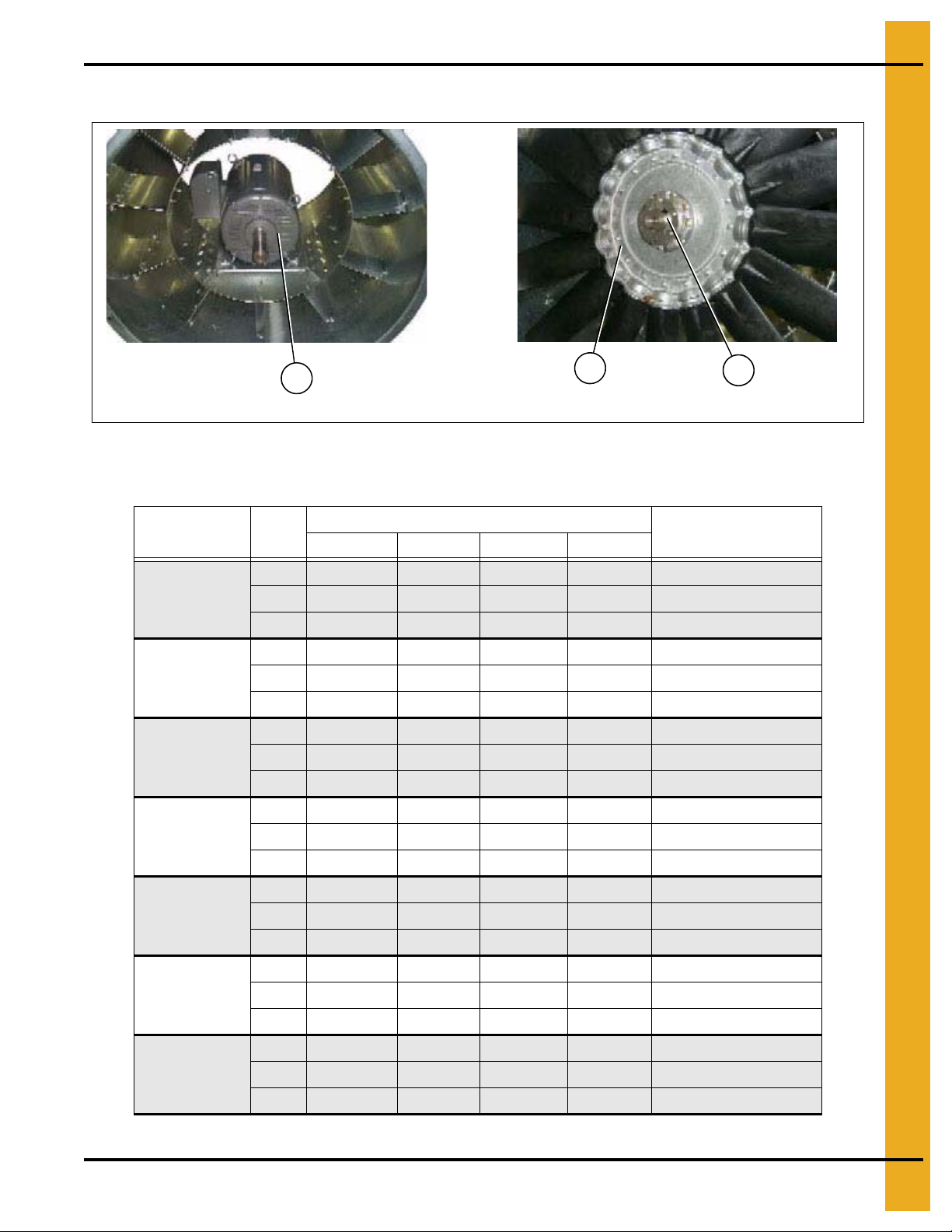
Fan Motor, Motor Mount and Fan Blade
Fan blade and bushing
Fan motor and motor mount
1
3
2
Figure 3G
Fan Motor, Motor Mount and Fan Blade Parts List
3. Fan/Heaters
Fan/Heater
(Diameter, HP)
36" 12 HP
36" 15 HP
40" 15 HP
42" 20 HP
42" 25 HP
42" 30 HP
Ref #
Part #
220V 1 PH 208V 3 PH 220V 3 PH 440V 3 PH
1 002-1075-7 CD-0239 CD-0239 CD-0239 Motor
2 D03-0302 D03-0302 D03-0302 D03-0302 Fan Blade
3 FH-1009 FH-1009 FH-1009 FH-1009 Bushing
1 CD-0580 MTR-0009 MTR-0009 MTR-0009 Motor
2 D82-0002 D82-0002 D82-0002 D82-0002 Fan Blade
3 FH-6963 FH-6963 FH-6963 FH-6963 Bushing
1 CD-0580 MTR-0009 MTR-0009 MTR-0009 Motor
2 D03-0914 D03-0914 D03-0914 D03-0914 Fan Blade
3 GC03810 GC03810 GC03810 GC03810 Bushing
1 N/A MTR-0010 MTR-0010 MTR-0010 Motor
2 N/A D01-0470 D01-0470 D01-0470 Fan Blade
3 N/A GC03810 GC03810 GC03810 Bushing
1 N/A MTR-0011 MTR-0011 MTR-0011 Motor
2 N/A D01-0471 D01-0471 D01-0471 Fan Blade
3 N/A CE-00617 CE-00617 CE-00617 Bushing
1 N/A MTR-0012 MTR-0012 MTR-0012 Motor
2 N/A D01-0472 D01-0472 D01-0472 Fan Blade
3 N/A CE-00617 CE-00617 CE-00617 Bushing
Description
1 N/A MTR-0030 MTR-0030 MTR-0030 Motor
42" 40 HP
PNEG-1914 Single Module Portable Dryer 61
2 N/A D01-0473 D01-0473 D01-0473 Fan Blade
3 N/A PT0784 PT0784 PT0784 Bushing
Page 62

3. Fan/Heaters
1a
2
1
Air Mixer Assemblies
Figure 3H Air Mixer Assemblies (36'' Air mixer shown in photo.)
Air Mixer Assemblies Parts List
Ref # Part # Description 36'' F/H 40'' F/H 42'' F/H
1-2 CD-0113 Air Mixer Assembly, 36" 1
1 and 1a D01-1303 Air Mixer Can, 36" with Access 2/Assembly
2 CD-0083 Air Mixer Vane 8/Assembly
1-2 CD-0117 Air Mixer Assembly, 40" 1
1 and 1a D01-1218 Air Mixer Can, 40" with Access 2/Assembly
2 CD-0083 Air Mixer Vane 8/Assembly
1-2 CD-0118 Air Mixer Assembly, 42" 1
1 and 1a CD-0192 Air Mixer Can, 42" 2/Assembly
2 CD-0083 Air Mixer Vane 8/Assembly
62 PNEG-1914 Single Module Portable Dryer
Page 63

Flame Probe, Ignitor and Burner Assemblies
3. Fan/Heaters
Figure 3I Switch Kit, Air Velocity Sensor, VN2 (D04-0906)
Switch Kit, Air Velocity Sensor, VN2 (D04-0906) Parts List
Ref # Part # Description Qty
1 TD-101361 Housing Assembly, Air Switch, TD + PD 1
2 D03-0167 Air Pressure Switch 1
3 D03-0166 Switch, Pressure Nut BEC Style 1
4 D03-0649 Elbow, 1/4" Clamp x 1/8" NPT Brass 1
5 FH-1310 Connector, Cord 1
6 006-1236-6 Lock Nut 1/2" NPT Nylon 1
7 HF-7463 Tube, 1/4" O.D. 3/16" I.D. UV Resist 1
8 006-1377-1 Connector, 1/2" Elec No-Met 90° 1
9 120-1538-4 Conduit, 1/2" Flexible Non-Met 1
10 006-1360-4 Connector, 1/2" Elec Non-Metal 1
11 FH-1309 Lock Nut 1/2" with Pipe Threads 2
12 S-9036 Screw, SMSB 1/4" x 3/4" HH ZN 4
13 054-1036-0 Clamp, 3/8" Insulated Metal 1
14 S-280 Screw, SDS #10-16 x 5/8" HWH ZN 1
PNEG-1914 Single Module Portable Dryer 63
Page 64

3. Fan/Heaters
Flame Probe, Ignitor and Burner Assemblies (Continued)
Figure 3J Conduit Package, Burner High-Limit LP VN2 (FCP-BHL-LP)
Conduit Package, Burner High-Limit LP VN2 (FCP-BHL-LP) Parts List
Ref # Part # Description Qty
1 D01-1473 Housing High-Limit Plate 1
2 027-1006-9 Thermostat, High-Limit 200°F AUTO 1
3 S-8472 Screw, TCSF #8-32 x 3/8" HWHS ZN 4
4 TFC-0076 Seal, Neoprene Conduit Body 1
5 THH-4064 Conduit, Unilet Type LRL Conduit box 1/2" 1
6 S-6550 Flat Washer #8 SAE ZN Grade S 2
7 S-280 Screw, SDS #10-16 x 5/8" HWH ZN 4
8 006-1360-4 Connector, 1/2" Elec Non-Metal 1
9 120-1538-4 Conduit, 1/2" Flexible Non-Metal 1
10 006-1371-0 Connector, 1/2" Elec Non-Metal 45° 1
11 FH-1310 Connector, Cord 1
64 PNEG-1914 Single Module Portable Dryer
Page 65

3. Fan/Heaters
Flame Probe, Ignitor and Burner Assemblies (Continued)
Figure 3K Ignitor Assembly, Portable Dryer, 1/8" Gap (TF-1558)
Ignitor Assembly, Portable Dryer, 1/8" Gap (TF-1558) Parts List
Ref # Part # Description Qty
1 HF-7204 Dual Probe Ignitor Bracket 1
2 CD-0238 Igniter, Flame 2
3 HF-7201 Ignitor Ha lf Clamp 2
4 S-2786 Screw, TCSF #8-32 x 3/8" PHP ZN 2
5 S-4614 Bolt, HHCS 1/4"-20 x 1/2" SS 2
6 S-4615 Hex Nut 1/4"-20 302 18.8 SS 1
7 D01-0878 Ignitor Air Deflector Angle 1
8 S-8114 Flange Nut 1/4"-20 SS 1
PNEG-1914 Single Module Portable Dryer 65
Page 66

3. Fan/Heaters
Flame Probe, Ignitor and Burner Assemblies (Continued)
Figure 3L Flame Sensor 6" Rod Assembly (THH-4182)
Flame Sensor 6" Rod Assembly (THH-4182) Parts List
Ref # Part # Description Qt y
1 CD-0187 Flame Sensor Bracket 1
2 S-4614 Bolt, HHCS 1/4"-20 x 1/2" SS 1
3 S-8114 Flange Nut 1/4"-20 SS 1
4 THH-4179 Rod, Flame Sensor 6" Long 1
5 FH-1309 Lock Nut 1/2" with Pipe Threads 2
66 PNEG-1914 Single Module Portable Dryer
Page 67

3. Fan/Heaters
See Figure 3L on Page 66 for instructions on
bending flame probe rod.
Flame Probe, Ignitor and Burner Assemblies (Continued)
Figure 3M Flame Probe Assembly Dri-Tek and Dri-Tek Plus (TF-1559-DT)
Flame Probe Assembly Dri-Tek and Dri-Tek Plus (TF-1559-DT) Parts List
Ref # Part # Description Qty
1 THH-4182 Flame Sensor 6" Rod Assembly 1
2 HH-7025 Boot, 8 mm Silicone 90° 1
3 HH-1106 Terminal, 3/16" Eyelet 1
4 S-8472 Screw, TCSF #8-32 x 3/8" HWHS ZN 1
PNEG-1914 Single Module Portable Dryer 67
Page 68

3. Fan/Heaters
Flame Probe, Ignitor and Burner Assemblies (Continued)
Figure 3N Burner Sub-Assembly, 36" PD Fan/Heater (D04-0806)
Burner Sub-Assembly, 36" PD Fan/Heater (D04-0806) Parts List
Ref # Part # Description Qt y
1 D04-0805 Burner Weldment, 36" PD Fan/Heater 1
2 D04-0899 Burner Cup Assembly, with Flame Tubes 36" 3-4.5MBTU 1
3 S-6673 Flat Washer 1/4" SS 3
4 S-4616 Bolt, HHCS 1/4"-20 x 1-1/4" 302 18.8 SS 3
5 S-8114 Flange Nut 1/4"-20 SS 3
6 S-8739 Flat Washer 3/8" x 1-1/2" x 1/4" TH 1
7 HH-7056 Cone, 36"/42" Burner S.S. 1
8 S-8956 Flange Bolt 5/16"-18 x 3/4" SS 1
68 PNEG-1914 Single Module Portable Dryer
Page 69

3. Fan/Heaters
Flame Probe, Ignitor and Burner Assemblies (Continued)
Figure 3O Burner Cup Assembly with Flame Tubes 36" (D04-0899)
Burner Cup Assembly with Flame Tubes 36" (D04-0899) Parts List
Ref # Part # Description Qty
1 D03-1143-MCH Burner Cup, 36" VN2 Fan/Heater 1
2 KD-PPF03040 Nipple, 3/8" x 4" SCH 40 Black 7
PNEG-1914 Single Module Portable Dryer 69
Page 70

3. Fan/Heaters
Flame Probe, Ignitor and Burner Assemblies (Continued)
Figure 3P Burner Sub-Assembly, 40" PD Fan/Heater (D04-0897)
Burner Sub-Assembly, 40" PD Fan/Heater (D04-0897) Parts List
Ref # Part # Description Qt y
1 D04-0896 Burner Weldment, 40" PD Fan/Heater 1
2 D04-0803 Burner Cup Assembly, with Flame Tubes 42" 6-10MBTU 1
3 S-6673 Flat Washer 1/4" SS 3
4 S-4616 Bolt, HHCS 1/4"-20 x 1-1/4" 302 18.8 SS 3
5 S-8114 Flange Nut 1/4"-20 SS 3
6 S-8739 Flat Washer 3/8" x 1-1/2" x 1/4" TH 1
7 HH-7056 Cone, 36"/42" Burner S.S. 1
8 S-8956 Flange Bolt 5/16"-18 x 3/4" SS 1
70 PNEG-1914 Single Module Portable Dryer
Page 71

3. Fan/Heaters
Flame Probe, Ignitor and Burner Assemblies (Continued)
Figure 3Q Burner Sub-Assembly, 42" PD Fan/Heater (D04-0802)
Burner Sub-Assembly, 42" PD Fan/Heater (D04-0802) Parts List
Ref # Part # Description Qty
1 D04-0801 Burner Weldment, 42" PD Fan/Heater 1
2 D04-0803 Burner Cup Assembly, with Flame Tubes 42" 6-10MBTU 1
3 S-6673 Flat Washer 1/4" SS 3
4 S-4616 Bolt, HHCS 1/4"-20 x 1-1/4" 302 18.8 SS 3
5 S-8114 Flange Nut 1/4"-20 SS 3
6 S-8739 Flat Washer 3/8" x 1-1/2" x 1/4" TH 1
7 HH-7056 Cone, 36"/42" Burner S.S. 1
8 S-8956 Flange Bolt 5/16"-1 8 x 3/4" SS 1
PNEG-1914 Single Module Portable Dryer 71
Page 72

3. Fan/Heaters
Flame Probe, Ignitor and Burner Assemblies (Continued)
Figure 3R Burner Cup Assembly with Flame Tubes 42" (D04-0803)
Burner Cup Assembly with Flame Tubes 42" (D04-0803) Parts List
Ref # Part # Description Qty
1 D03-1115-MCH Burner Cup, 40"-42" VN2 Fan/Heater 1
2 KD-PPF03040 Nipple, 3/8" x 4" SCH 40 Black 8
72 PNEG-1914 Single Module Portable Dryer
Page 73

Fan/Heater Assembly
3. Fan/Heaters
Figure 3S Fan/Heater 36" 12 HP 230V 1 PH LP, VN2, CSA (3616V-2L-U)
NOTE: The parts pointed out on this page are listed on Page 80.
PNEG-1914 Single Module Portable Dryer 73
Page 74

3. Fan/Heaters
Fan/Heater Assembly (Continued)
Figure 3T Fan/Heater 36" 12 HP 230V 1 PH LP, VN2, CSA (3616V-2L-U)
NOTE: The parts pointed out on this page are listed on Page 80.
74 PNEG-1914 Single Module Portable Dryer
Page 75

Fan/Heater Assembly (Continued)
3. Fan/Heaters
Figure 3U Fan/Heater 36" 12 HP 230V 1 PH LP, VN2, CSA (3616V-2L-U)
NOTE: The parts pointed out on this page are listed on Page 80.
PNEG-1914 Single Module Portable Dryer 75
Page 76

3. Fan/Heaters
Fan/Heater Assembly (Continued)
Figure 3V Fan/Heater 36" 12 HP 230V 1 PH LP, VN2, CSA (3616V-2L-U)
NOTE: The parts pointed out on this page are listed on Page 80.
76 PNEG-1914 Single Module Portable Dryer
Page 77

Fan/Heater Assembly (Continued)
3. Fan/Heaters
Figure 3W Fan/Heater 36" 12 HP 230V 1 PH LP, VN2, CSA (3616V-2L-U)
NOTE: The parts pointed out on this page are listed on Page 80.
PNEG-1914 Single Module Portable Dryer 77
Page 78

3. Fan/Heaters
Fan/Heater Assembly (Continued)
Figure 3X Fan/Heater 36" 12 HP 230V 1 PH LP, VN2, CSA (3616V-2L-U)
NOTE: The parts pointed out on this page are listed on Page 80.
78 PNEG-1914 Single Module Portable Dryer
Page 79

Fan/Heater Assembly (Continued)
3. Fan/Heaters
Figure 3Y Fan/Heater 36" 12 HP 230V 1 PH LP, VN2, CSA (3616V-2L-U)
NOTE: The parts pointed out on this page are listed on Page 80.
PNEG-1914 Single Module Portable Dryer 79
Page 80

3. Fan/Heaters
Fan/Heater 36" 12 HP 230V 1 PH LP, VN2, CSA (3616V-2L-U) Parts List
Ref # Part # Description Qty
1 FHA-3615-VN2 Fan Housing Assembly, 36"-15 HP, VN2 1
2 FCP-BHL-LP Conduit Package, Burner High-Limit LP VN2 1
3 D04-0910 Sensor Kit, Velocity Pressure, PD 1
4 ADA-GENESIS Door Assembly, Burner Access, Vision Fan/Heaters 1
5 APA-36VN2 Adapter Plate Assembly 36" Vision N2 1
6 D04-0906 Switch Kit, Air Velocity Sensor, VN2 1
7 FDP-3612-2V Fan Drive Package, 36"-12 HP, 230V 3 PH, VN2 1
8 CD-FBA3610 PD Prop Assembly, 36"-10 HP, Composite 1
9 D04-0806 Burner Assembly, 36" PD Fan/Heater, VN2 1
10 S-7928 Flange Bolt 3/8"-16 x 1-1/2" YDP Grade 8 4
11 S-968 Flange Nut 3/8"-16 ZN Grade 5 4
12 TF-1558 Ignitor Assembly, Portable Dryer, 1/8" Gap 1
13 TF-1559-DT Flame Probe Assembly Dri-Tek and Dri-Tek Plus 1
14 FN2-12HP-2LG Fan Control Box 12 HP 208-230V 3P N2 Vision 1
15 D04-0934 Pipe Train Assembly, 36"-12 HP LP, VN2 1
16 D04-0933 Vaporizer Kit 1/2" NPT, 9" Coil, VN2 1
80 PNEG-1914 Single Module Portable Dryer
Page 81

Fan/Heater Assembly (Continued)
3. Fan/Heaters
Figure 3Z Fan/Heater 40" 15 HP 230V 3 PH LP VN2 (4015V-2L-U)
NOTE: The parts pointed out on this page are listed on Page 87.
PNEG-1914 Single Module Portable Dryer 81
Page 82

3. Fan/Heaters
Fan/Heater Assembly (Continued)
Figure 3AA Fan/Heater 40" 15 HP 230V 3 PH LP VN2 (4015V-2L-U)
NOTE: The parts pointed out on this page are listed on Page 87.
82 PNEG-1914 Single Module Portable Dryer
Page 83

Fan/Heater Assembly (Continued)
3. Fan/Heaters
Figure 3AB Fan/Heater 40" 15 HP 230V 3 PH LP VN2 (4015V-2L-U)
NOTE: The parts pointed out on this page are listed on Page 87.
PNEG-1914 Single Module Portable Dryer 83
Page 84

3. Fan/Heaters
Fan/Heater Assembly (Continued)
Figure 3AC Fan/Heater 40" 15 HP 230V 3 PH LP VN2 (4015V-2L-U)
NOTE: The parts pointed out on this page are listed on Page 87.
84 PNEG-1914 Single Module Portable Dryer
Page 85

Fan/Heater Assembly (Continued)
3. Fan/Heaters
Figure 3AD Fan/Heater 40" 15 HP 230V 3 PH LP VN2 (4015V-2L-U)
NOTE: The parts pointed out on this page are listed on Page 87.
PNEG-1914 Single Module Portable Dryer 85
Page 86

3. Fan/Heaters
Fan/Heater Assembly (Continued)
Figure 3AE Fan/Heater 40" 15 HP 230V 3 PH LP VN2 (4015V-2L-U)
Figure 3AF Fan/Heater 40" 15 HP 230V 3 PH LP VN2 (4015V-2L-U)
NOTE: The parts pointed out on this page are listed on Page 87.
86 PNEG-1914 Single Module Portable Dryer
Page 87

3. Fan/Heaters
Fan/Heater 40" 15 HP 230V 3 PH LP VN2 (4015V-2L-U) Parts List
Ref # Part # Description Qty
1 FHA-4015-VN2 Fan Housing Assembly, 40"-15 HP, VN2 1
2 FCP-BHL-LP Conduit Package, Burner High-Limit, LP, VN2 1
3 D04-0910 Sensor Kit, Velocity Pressure, PD 1
4 ADA-GENESIS Door Assembly, Burner Access, Vision Fan/Heaters 1
5 APA-42VN2 Adapter Plate Assembly 42" Vision N2 1
6 D04-0906 Switch Kit, Air Velocity Sensor, VN2 1
7 FDP-4015-2V Fan Drive Package, 40"-15 HP, 208-230V 3 PH, VN2 1
8 CD-FBA4015 PD Prop Assembly, 40"-15 HP, Composite 1
9 D04-0897 Burner Sub-Assembly, 40" PD Fan/Heater 1
10 S-7928 Flange Bolt 3/8"-16 x 1-1/2" YDP Grade 8 4
11 S-968 Flange Nut 3/8"-16 ZN Grade 5 4
12 TF-1558 Ignitor Assembly, Portable Dryer, 1/8" Gap 1
13 TF-1559-DT Flame Probe Assembly Dri-Tek and Dri-Tek Plus 1
14 FN2-15HP-2LG Fan Control Box 15 HP 208-230V 3P N2 VIS 1
15 D04-0905 Pipe Train Assembly, 40"-15 HP LP, VN2 1
16 D04-0907 Vaporizer Kit 1/2" NPT, 22" Coil, VN2 1
PNEG-1914 Single Module Portable Dryer 87
Page 88

3. Fan/Heaters
Fan/Heater Assembly (Continued)
Figure 3AG Fan/Heater 42" 20 HP 230V 3 PH LP, VN2 (4220V-2L-U)
NOTE: The parts pointed out on this page are listed on Page 95.
88 PNEG-1914 Single Module Portable Dryer
Page 89

Fan/Heater Assembly (Continued)
3. Fan/Heaters
Figure 3AH Fan/Heater 42" 20 HP 230V 3 PH LP, VN2 (4220V-2L-U)
NOTE: The parts pointed out on this page are listed on Page 95.
PNEG-1914 Single Module Portable Dryer 89
Page 90

3. Fan/Heaters
Fan/Heater Assembly (Continued)
Figure 3AI Fan/Heater 42" 20 HP 230V 3 PH LP, VN2 (4220V-2L-U)
NOTE: The parts pointed out on this page are listed on Page 95.
90 PNEG-1914 Single Module Portable Dryer
Page 91

Fan/Heater Assembly (Continued)
3. Fan/Heaters
Figure 3AJ Fan/Heater 42" 20 HP 230V 3 PH LP, VN2 (4220V-2L-U)
NOTE: The parts pointed out on this page are listed on Page 95.
PNEG-1914 Single Module Portable Dryer 91
Page 92

3. Fan/Heaters
Fan/Heater Assembly (Continued)
Figure 3AK Fan/Heater 42" 20 HP 230V 3 PH LP, VN2 (4220V-2L-U)
NOTE: The parts pointed out on this page are listed on Page 95.
92 PNEG-1914 Single Module Portable Dryer
Page 93

Fan/Heater Assembly (Continued)
3. Fan/Heaters
Figure 3AL Fan/Heater 42" 20 HP 230V 3 PH LP, VN2 (4220V-2L-U)
NOTE: The parts pointed out on this page are listed on Page 95.
PNEG-1914 Single Module Portable Dryer 93
Page 94

3. Fan/Heaters
Fan/Heater Assembly (Continued)
Figure 3AM Fan/Heater 42" 20 HP 230V 3 PH LP, VN2 (4220V-2L-U)
NOTE: The parts pointed out on this page are listed on Page 95.
94 PNEG-1914 Single Module Portable Dryer
Page 95

3. Fan/Heaters
Fan/Heater 42" 20 HP 230V 3 PH LP, VN2 (4220V-2L-U) Parts List
Ref # Part # Description Qty
1 FHA-4220-VN2 Fan Housing Assembly, 42"-20 HP, VN2 1
2 FCP-BHL-LP Conduit Package, Burner High-Limit LP VN2 1
3 D04-0910 Sensor Kit, Velocity Pressure, PD 1
4 ADA-GENESIS Door Assembly, Burner Access, Vision Fan/Heaters 1
5 APA-42VN2 Adapter Plate Assembly 42" Vision N2 1
6 D04-0906 Switch Kit, Air Velocity Sensor, VN2 1
7 FDP-4220-2V Fan Drive Package, 42"-20 HP, 230V 3 PH, VN2 1
8 CD-FBA4220 PD Prop Assembly , 42"-20 HP, Composite 1
9 D04-0802 Burner Assembly , 42" PD Fan/Heater, VN2 1
10 TF-1558 Ignitor Assembly, Port able Dryer, 1/8" Gap 1
11 TF-1559-DT Flame Probe Assembly Dri-Tek and Dri-Tek Plus 1
12 FN2-20HP-2LG Fan Control Box 20 HP 220V 3P N2 VIS 1
13 D04-0932 Pipe Train Assembly, 42"-20 HP LP, VN2 1
14 D04-0907 Vaporizer Kit 1/2" NPT, 22" Coil, VN2 1
PNEG-1914 Single Module Portable Dryer 95
Page 96

3. Fan/Heaters
LP Pipe Train Assemblies
Figure 3AN Pipe Train Assembly 40"-15 HP LP, VN2 (D04-0905)
Pipe Train Assembly 40"-15 HP LP, VN2 (D04-0905) Parts List
Ref # Part # Description
1 PTA-36LP-GEN Pipe Train Sub-Assembly 36" LP Vision 1 1
PTA-40LP-GEN Pipe Train 40" LP Vision 1 1
PTA-42LP-GEN Pipe Train 42" LP Vision 1 1 1
2 D08-0022 Gauge, Pressure 0-15# Liquid Filled 1 1 1 1 1 1 1
THF-3242 Orifice Tube 36",10-12 HP LP 9/32" 1
CD-0150 Orifice Tube 36" 15 HP LP 21/64 1
THF-3058 Orifice Tube 42" 15 HP PV .344" 1
3
THF-3247 Orifice Tube 42", 20 HP LP 3/8" 1
THF-3249 Orifice Tube 42",25 HP LP 25/64 25/64" 1
THF-3059 Orifice Tube 40", 1" NPT x 0.438" (7/16") 1
THF-3252 Orifice Tube 42", 40 HP LP 29/64" 1
4 FH-1310 Connector, Cord 1 1 1 1 1 1 1
5 PTA-MHP-F Pipe Train Mount Hardware Package FFI 1 1 1 1 1 1 1
6 D04-0823 Support Kit, LP Strainer - 1/2" NPT 1 1 1 1 1 1 1
3612 3615 4015 4220 4225 4230 4240
Qty
96 PNEG-1914 Single Module Portable Dryer
Page 97

LP Pipe Train Assemblies (Continued)
3. Fan/Heaters
Figure 3AO Pipe Train Sub-Assembly 36" LP Vision (PTA-36LP-GEN)
Pipe Train Sub-Assembly 36" LP Vision (PTA-36LP-GEN) Parts List
Ref # P art # Description Qty
1 HH-1082 Elbow, 1/2"-90 Street SCH 80 Black 1
2 HH-1251 Strainer, 1/2" Y 250# WOG SCH 80 Black, with Plug 1
3 D07-0019 Nipple, 1/2 " x 1-1/2" SCH 80 Black 2
4 HH-4846 Tee, 1/2" x 1/2" x 1/4" SCH 80 Black 1
5 031-1008-7 Valve, Pressure Relief 300 PSI 1
6 TFC-0023-50 Regulator, 1/2" NPT 1
7 HH-2029 Nipple, 1/2 " x 1-1/2" SCH 40 Black 2
8 HH-1453 Tee, 1/2" x 1/2" x 1/2" MI Cl150 Malleable Iron Class 150 1
9 HH-7013 Switch, Screw-In Vapor High-Limit 200F 1
10 THH-4071 Elbow, 1/2"-90° SCH 40 Black 1
11 THH-4149 Elbow, 3/4"-1/2" Reduce SCH 40 1
12 THH-4125 Nipple, 3/4" x 2" SCH 40 Black 3
13 056-2228-7 Valve, Solenoid 3/4" NPT 115V Din Bypass 1
14 THH-4066 Elbow, 3/4"-90 Street SCH 40 Black 1
15 056-2223-8 Valve, Solenoid 3/4" NPT 115V Din 1
16 THH-4136 Nipple, 3/4" x 3" SCH 40 Black 1
17 THH-4154 Tee, 3/4" x 3/4" x 1/4" SCH 40 Black 1
18 007-1048-3 Valve, Ball 3/4" with Lever Handle 1
19 007-1248-9 Nipple, 3/4 x 1-1/2" SCH 40 Black 1
20 THH-4120 Elbow, 3/4"-90 SCH 40 Black 1
PNEG-1914 Single Module Portable Dryer 97
Page 98

3. Fan/Heaters
LP Pipe Train Assemblies (Continued)
Figure 3AP Pipe Train 40" LP Vision (PTA-40LP-GEN)
Pipe Train 40" LP Vision (PTA-40LP-GEN) Parts List
Ref # Part # Description Qty
1 HH-1082 El bow, 1/2"-90 Street SCH 80 Black 1
2 HH-1251 Strainer, 1/2" Y 250# WOG SCH 80 Black, with Plug 1
3 D07-0019 Nipple, 1/2" x 1-1/2" SCH 80 Black 2
4 HH-4846 Tee, 1/2" x 1/2" x 1/4" SCH 80 Black 1
5 031-1008-7 Valve, Pressure Relief 300 PSI 1
6 TFC-0023-50 Regulator, 1/2" NPT 1
7 HH-2029 N ipple, 1/2" x 1-1/2" SCH 40 Black 2
8 HH-1453 Tee, 1/2" x 1/2" x 1/2" MI Cl150 Malleable Iron Class 150 1
9 HH-7013 Sw itch, Screw-In Vapor High-Limit 200F 1
10 THH-4071 Elbow, 1/2"-90° SCH 40 Black 1
11 THH-4153 Elbow, 1" x 1/2"-90° Reducing SCH 40 1
12 THH-4117 Nipple, 1" Close SCH 40 Black 2
13 056-2230-3 Valve, Solenoid 1" NPT 115V Din with Bypass 1
14 THH-4037 Nipple, 1" x 2-1/2" SCH 40 Black 3
15 THH-4115 Elbow, 1"-90° SCH 40 Black 2
16 056-2224-6 Valve, Solenoid 1" NPT 115V Din 1
17 THH-4152 Tee, 1" x 1" x 1/4" SCH 40 Black 1
18 007-1242-2 Nipple, 1" x 2" SCH 40 Black 1
19 007-1296-8 Valve, Ball 1" with Lever Handle 1
98 PNEG-1914 Single Module Portable Dryer
Page 99

LP Pipe Train Assemblies (Continued)
3. Fan/Heaters
Figure 3AQ Pipe Train 42" LP Vision (PTA-42LP-GEN)
Pipe Train 42" LP Vision (PTA-42LP-GEN) Parts List
Ref # P art # Description Qty
1 HH-1082 Elbow, 1/2"-90 Street SCH 80 Black 1
2 HH-1251 Strainer, 1/2" Y 250# WOG SCH 80 Black, with Plug 1
3 HF-7586 Nipple, 1/2" x 2" SCH 80 Black 2
4 HH-4846 Tee, 1/2" x 1/2" x 1/4" SCH 80 Black 1
5 031-1008-7 Valve, Pressure Relief 300 PSI 1
6 TFC-0023-50 Regulator, 1/2" NPT 1
7 HH-2029 Nipple, 1/2 " x 1-1/2" SCH 40 Black 2
8 HH-1453 Tee, 1/2" x 1/2" x 1/2" MI Cl150 Malleable Iron Class 150 1
9 HH-7013 Switch, Screw-In Vapor High-Limit 200F 1
10 THH-4071 Elbow, 1/2"-90° SCH 40 Black 1
11 THH-4153 Elbow, 1" x 1/2"-90° Reducing SCH 40 1
12 THH-4117 Nipple, 1" Close SCH 40 Black 2
13 056-2230-3 Valve, Solenoid 1" NPT 115V Din with Bypass 1
14 007-1242-2 Nipple, 1" x 2" SCH 40 Black 4
15 THH-4115 Elbow, 1"-90° SCH 40 Black 2
16 056-2224-6 Valve, Solenoid 1" NPT 115V Din 1
17 D08-0017 Tee, 1" x 1" x 3/4" SCH 40 Black 1
18 D07-0027 Bushing, Reducer 3/4" x 1/4" Hex SCH 40 Black 1
19 007-1296-8 Valve, Ball 1" with Lever Handle 1
PNEG-1914 Single Module Portable Dryer 99
Page 100

3. Fan/Heaters
Vaporizer Assembly
Figure 3AR Vaporizer Kit 1/2" NPT, 9" Coil, VN2 (D04-0933)
Vaporizer Kit 1/2" NPT, 9" Coil, VN2 (D04-0933) Parts List
Ref # Part # Description Qty
1 D01-2217-BK Vaporizer Support Plate, Black 1
2 410-1783-1-B Vaporizer Adjusting Weld 1/2" 1
3 CD-0197 Vaporizer Coil for Downwind Heaters 1
4 S-6606 Flange Bolt 5/16"-18 x 3/4" ZN Grade 5 4
5 S-3611 Flange Nut 5/16"-18 YDP Grade 2 2
6 S-1430 Flat Washer 1/4" ZN Grade 2 USS 4
7 S-9036 Screw, SMSB 1/4" x 3/4" HH ZN 4
8 HH-4847 Elbow, 1/2"-90° SCH 80 Black 2
9 TFC-0095 Hose, LP Gas 1/2" x 24" 2
100 PNEG-1914 Single Module Portable Dryer
 Loading...