

Page 1
Instructions
PNEG-1902
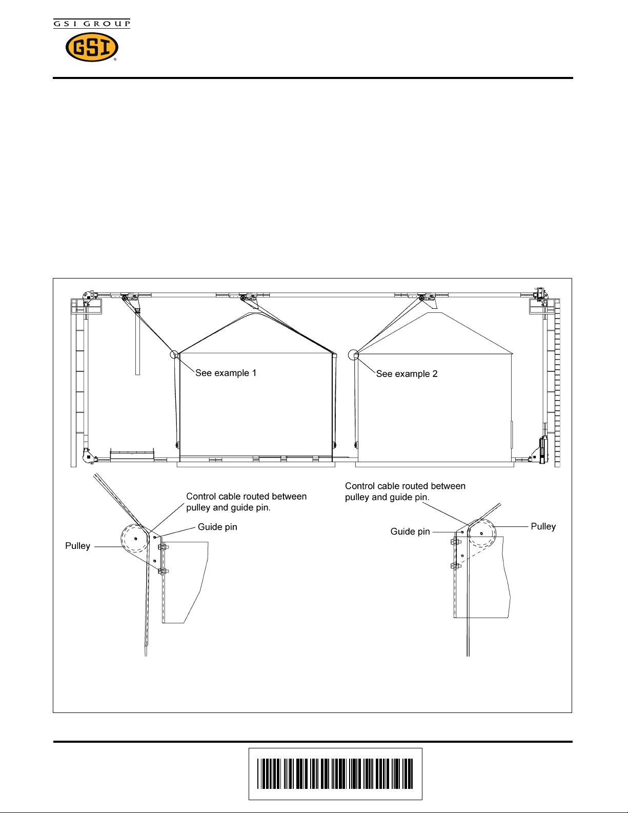
Example 2
Controls mounted
on adjacent bin.
Example 1
Controls mounted on bin
where the discharge is located.
1004 East Illinois Street • Assumption, IL 62510 • 1-217-226-4421
Discharge Gate Ground Control Kit
Chain Loop System - Ground Control Kit
Ground Control Kit for Discharge Gates
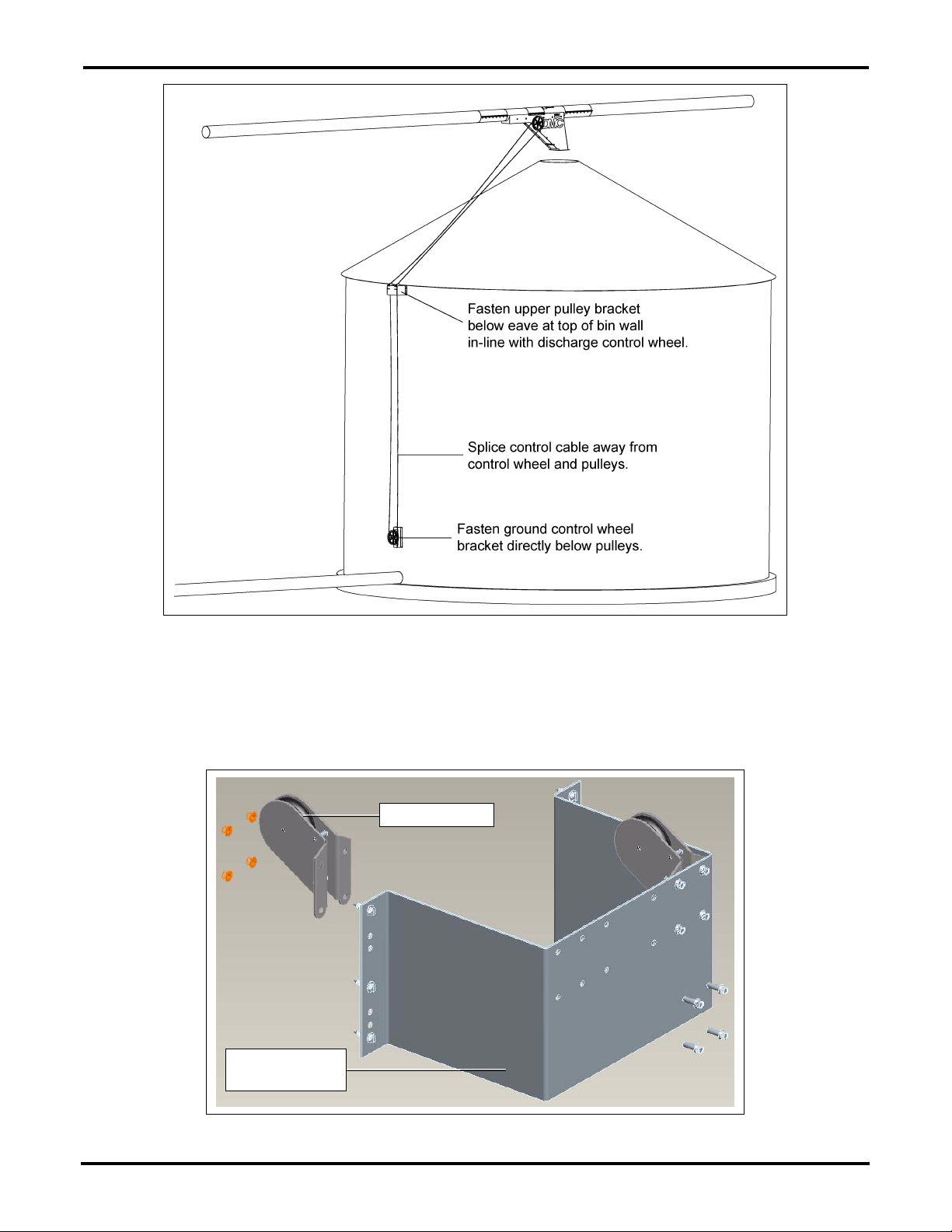
Determine the best location for each ground control kit. Note that each kit comes with 100' of cable, which
should be adequate for individual bin installations.
The cable idler pulley bracket is usually mounted at the top of the bin wall, just under the roof eave, in-line
with the control wheel on the discharge gate. The ground control wheel mounting bracket should be
mounted to the bin wall directly under the idler pulley bracket at a convenient operating height. It is
important to keep the cable in-line with the control wheels on both the discharge gate and at the ground
to avoid having the cable “walk off” the either wheel.
The ground control wheel can be mounted to the same bin as the discharge gate or to an adjacent bin.
See examples 1 and 2 in Figure 1.
Figure 1
Date: 12-14-12 PNEG-1902
Printed in the U.S.A.
Copyright © 2012 by GSI Group
www.gsiag.com
Page 1 of 7
CN-301901
Page 2
Discharge Gate Ground Control Kit
Mounting bracket
(8101156)
Pulley (PT0550)
Figure 2
1. Assemble the idler pulleys to the mounting bracket on the inside surface if the cable is going to a
discharge gate on the same bin. Assemble them on the outside if the cable is going to an adjacent
bin. Attach the idler pulley bracket to the bin wall just under the eave to ensure that the cable will
clear the bin roof. (See Figure 3.)
Page 2 of 7 PNEG-1902
Figure 3
Page 3
Discharge Gate Ground Control Kit
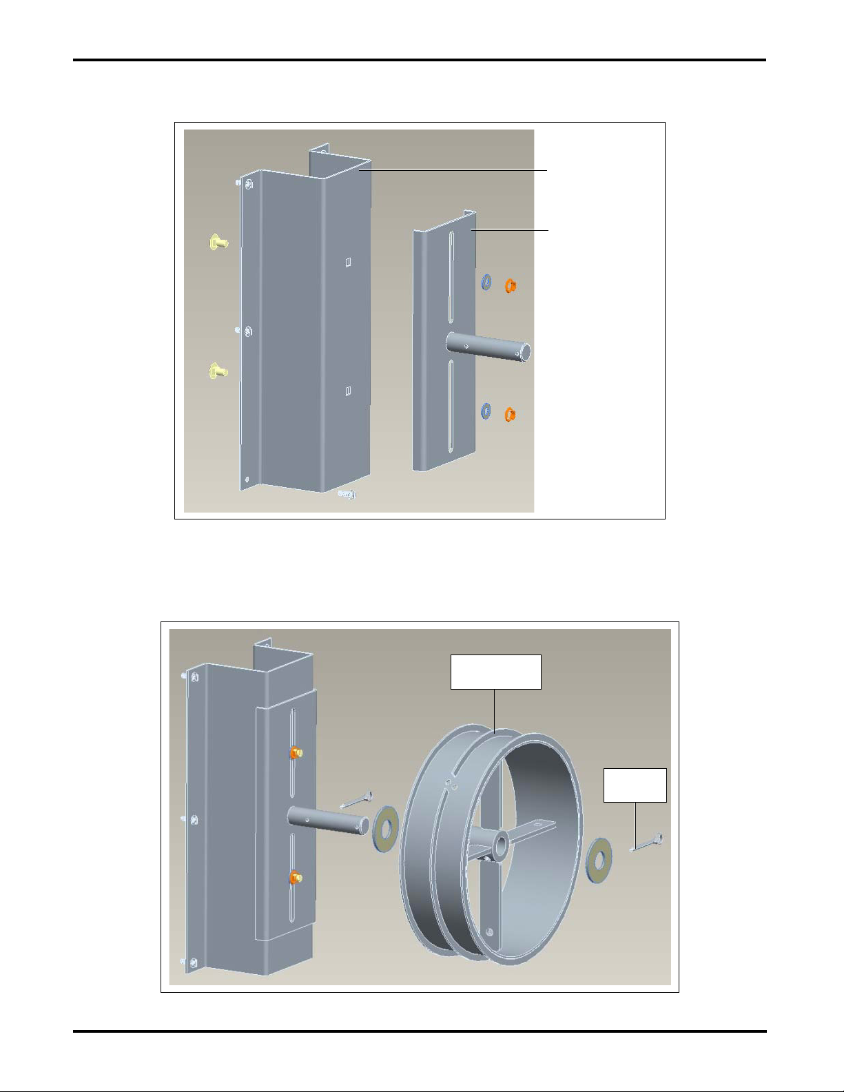
Bin wall mounting
bracket (8101157)
Wheel mounting
bracket (8101158)
Wheel drum
(8101537-GY)
Cotter pin
(S-6994)
2. Attach the ground control wheel bracket to the bin wall directly below the idler bracket. Assemble the
wheel mounting bracket loosely to the wall bracket and slide it up as far as possible.
(See Figure 4.)
Figure 4
3. Assemble the control wheel to the shaft and secure with cotter pins. (See Figure 5.)
NOTE: It is recommended to use anti seize on the shaft.
PNEG-1902 Page 3 of 7
Figure 5
Page 4

Discharge Gate Ground Control Kit
Wheel drum
(8101537-GY)
Handle bracket
(8101540-GY)
Handle (8101541-GY)
Handle bracket
(8101540-GY)
Roller (GSB-0050)
4. Assemble the handle brackets to the bottom side of the control wheel spokes. (See Figure 6.)
Figure 6
5. Attach the handle to the handle mount brackets. Assemble the roller to the handle. (See Figure 7.)
Page 4 of 7 PNEG-1902
Figure 7
Page 5

Discharge Gate Ground Control Kit
6. Completely open the discharge gate and wrap the cable six (6) times counterclockwise around the
outside section (closest to you) of the discharge gate control wheel starting outside and working
towards the middle. Use cable clamp to secure the cable to the control wheel. Cross the cable to
the inside section of the discharge gate control wheel and wrap the cable two (2) times starting at
the middle and working towards the outside. (See Figure 8.)
NOTE: The cable should never be wrapped on top of itself.
Figure 8
7. Make sure the discharge gate is still completely open.
8. Route the cable back through the idler pulleys and down to the ground control wheel.
9. Wrap the cable two (2) times counterclockwise around the outside section of the discharge gate
control wheel starting outside and working towards the middle. Use cable clamp to secure the cable
to the control wheel. Cross the cable to the inside section of the discharge gate control wheel and
wrap the cable six (6) times starting at the middle and working towards the outside.
NOTE: The cable should never be wrapped on top of itself.
10. Splice the ends of the cable with two (2) cable clamps. With the gate completely open, the splice
should be at least 10' away from the pulleys and control wheels.
11. Slide the ground wheel bracket down to take up any slack in the cable and tighten in place.
12. Check the installation by turning the ground wheel clockwise to fully close the discharge gate and
counterclockwise to fully open the gate without any restrictions from the cable splice or the clamps
on the control wheels.
Operation of Control Kit
Each control system should be marked to identify which discharge gate is being controlled.
Each control system should be marked after installation to clearly identify whether the discharge gate is
open or closed.
PNEG-1902 Page 5 of 7
Page 6

Discharge Gate Ground Control Kit
Page 6 of 7 PNEG-1902
Page 7

Discharge Gate Ground Control Kit
Ref # Part # Description
1 8101157 Ground Control Kit Bin Wall Mount Bracket 1
2 8101158 Ground Control Kit Wheel Weldment 1
3 8101537-GY Ground Control: Wheel Drum Weld 1" 1
4 8101541-GY Ground Control: Handle 1
5 8101540-GY Ground Control: Handle Bracket 2
6 GSB-0050 Hand Roller 1-1/2" O.D. 1
7 8101156 Ground Control Kit Pulley Mount Bracket 1
8 PT0550 Pulley, Hot House 2
9 S-7391 Carriage Bolt 3/8"-16 x 3/4" ZN Grade 5 2
10 S-7409 Flat Washer 3/8" SAE ZN Grade 2 2
11 S-968 Flange Nut 3/8"-16 ZN Grade 5 Wide Flange 6
12 S-6994 Cotter Pin 3/16" x 2" ZN Grade 2 2
13 S-8762 Clamp, 3/16" Cable Zinc Plated 4
Assembly
Qty per
14 S-7835 Flat Washer 1" I.D. USS Washer Low Carbon 2
15 S-9067 Flange Bolt 3/8"-16 x 3/4" ZN Grade 5 4
16 S-8166 Screw, SMSAB 1/4" x 1" HWH ZN 12
17 S-8506 Flange Nut 1/2"-13 ZN 2
18 S-2121 Flat Washer 1/2" 2
19 S-8377 Bolt, HHCS 1/2"-13 x 6" ZN Grade 5 1
20 S-8680 Flange Bolt 1/4"-20 x 3/4" ZN Grade 5 8
21 S-7215 Flange Nut 1/4"-20 ZN 8
N/S 8109050 Cable 145' Roll 3/16" Diameter - 7 x 19 1
PNEG-1902 Page 7 of 7
 Loading...