

Page 1

PNEG-1895
V2 Electronic Distributor Control
Installation and Operation Manual
PNEG-1895
Date: 09-19-13
Page 2

2 PNEG-1895 V2 Electronic Distributor Control
Page 3

Table of Contents
Contents
Chapter 1 Safety ..................................................................................................................................................... 4
Safety Guidelines .................................................................................................................................. 4
Safety Instructions ..................... ... .... .......................................... ... ........................................................ 5
Chapter 2 Decals .................................................................................................................................................... 7
Chapter 3 Electrical Installation ........................................................................................................................... 8
Introduction ........................................................................................................................................... 8
Wire and Fitting Selection Requirements ................................... ... ... ............................................. ........ 8
Control Panel Cable to Distributor Fitting Connections ......................................................................... 9
Motor Cable to Motor Junction Box Fitting Connections ..................................... .... ... ... ... ... .... ... ... ... ... 10
Electric Motor Wiring Diagram ............................................................................................................ 11
Motor Wiring Electrical Connections ................................................................................................... 12
Sensor Wiring Connections to Connector Box .................................................................................... 13
Enclosure Covers Installation .............................................................................................................. 14
Control Panel Installation Guidelines .................................................................................................. 15
Electric Motor Connections at Control Panel ...................................................................................... 16
Sensor Terminations in Control Panel ................................................................................................ 17
Power Supply Wiring to Control Panel Electrical Connections ........................................................... 18
Chapter 4 Operation Procedures ........................................................................................................................ 19
Initializing Screen ...................................... ... .... ... ... .......................................... ... ................................ 19
Start-Up Checklist ........................................ .... .......................................... ... ...................................... 20
Main Screen ........................................................................................................................................ 21
Move Position Screen ................................................... ...................................... .... ... ... ... ... ....... ... ... ... 22
Setup Menu Screen ............................ ... ... ... .... ... ... ... .... .......................................... ... ......................... 23
Help Menu Screen .............................................................................................................................. 32
Manual Override ........................ ... .... ... .......................................... ... ............................................. ... ... 36
Chapter 5 Parts List ............................................................................................................................................. 38
12" 6 Hole 45° Distributor Assembly Electronic Control (DFB12645G-EC) ........................................ 38
Chapter 6 Retrofit Installation ..................................... .................... ...................... .............................................. 40
Electronic Distributor Control Shaft Installation ................................................................................... 40
Electronic Distributor Enclosure Installation ........................................... ............................................. 41
Sensor Plate Angle and Proximity Sensor Bracket Installation .................. ... ... ... ................................ 42
Proximity Sensor Location and Installation ......................................................................................... 43
Proximity Sensor Adjustment .............................................................................................................. 45
Encoder and Bracket Installation ........................................................................................................ 46
Installing the Connector Box and Cables ............................... .... ... ... ... .......................................... ...... 49
Motor Mounting Bracket Installation ................................. ................................................ ................... 50
Control Motor Installation .................................................................................................................... 51
Chapter 7 Troubleshooting ................................................................................................................................. 52
Error Messages ................................................................................................................................... 52
Fault Code Descriptions, Possible Causes and Solutions .................................................................. 54
Chapter 8 Schematic and Wiring Diagrams ...................................................................................................... 57
White Panel Layout ............................................................................................................................. 57
White Panel Electrical Schematic ..............................................................................................
Chapter 9 Warranty .............................................................................................................................................. 61
......... 58
PNEG-1895 V2 Electronic Distributor Control 3
Page 4

1. Safety
This is the safety alert symbol. It is used to alert you
to potential personal injury hazards. Obey all safety
messages that follow this symbol to avoid possible
injury or death.
WARNING indicates a hazardous situation which, if not
avoided, could result in death or serious injury.
CAUTION, used with the safety alert symbol, indicates a
hazardous situation which, if not avoided, could result in
minor or moderate injury.
NOTICE is used to address practices not related to
personal injury.
DANGER indicates a hazardous situation which, if not
avoided, will result in death or serious injury.
Safety Guidelines
This manual contains information that is important for you, the owner/operator, to know and understand.
This information relates to protecting personal safety and preventing equipment problems. It is the
responsibility of the owner/operator to inform anyone operating or working in the area of this equipment
of these safety guidelines. To help you recognize this information, we use the symbols that are defined
below. Please read the manual and pay attention to these sections. Failure to read this manual and its
safety instructions is a misuse of the equipment and may lead to serious injury or death.
DANGER
WARNING
CAUTION
NOTICE
4 PNEG-1895 V2 Electronic Distributor Control
Page 5
1. Safety
Follow Safety Instructions
Carefully read all safety messages in this manual and
safety signs on your machine. Keep signs in good
condition. Replace missing or damaged safety signs. Be
sure new equipment components and repair parts include
the current safety signs. Replacement safety signs are
available from the manufacturer.
Learn how to operate the machine and how to use controls
properly. Do not let anyone operate without instruction.
Keep your machinery in proper working condition.
Unauthorized modifications to the machine may impair
the function and/or safety and affect machine life.
If you do not understand any part of this manual or need
assistance, contact your dealer.
Read and Understand Manual
Practice Safe Maintenance
Understand service procedures before doing work. Keep area
clean and dry.
Never lubricate, service, or adjust machine while it is in operation.
Keep hands, feet and clothing away from rotating parts.
Keep all parts in good condition and properly installed. Fix
damage immediately . Replace worn or broken p arts. Remove any
built-up grease, oil, and debris.
Maintain Equipment
and Work Area
Safety Instructions
Our foremost concern is your safety and the safety of others associated with this equipment. We want to
keep you as a customer. This manual is to help you understand safe operating procedures and some
problems that may be encountered by the operator and other personnel.
As owner and/or operator, it is your responsibility to know what requirements, hazards, and precautions
exist, and to inform all personnel associated with the equipment or in the area. Safety precautions may be
required from the personnel. Avoid any alterations to the equipment. Such alterations may produce a very
dangerous situation where SERIOUS INJURY or DEATH may occur.
This equipment shall be installed in accordance with the current installation codes and applicable
regulations, which should be carefully followed in all cases. Authorities having jurisdiction should be
consulted before installations are made.
PNEG-1895 V2 Electronic Distributor Control 5
Page 6

1. Safety
Prepare for Emergencies
Be prepared if fire starts.
Keep a first aid kit and fire extinguisher handy.
Keep emergency numbers for doctors, ambulance service,
hospital, and fire department near your telephone.
Keep Emergency Equipment
Quickly Accessible
Wear Protective Clothing
Wear close-fitting clothing and safety equipment appropriate
to the job.
Remove all jewelry.
Tie long hair up and back.
Wear safety glasses at all times to protect eyes from debris.
Wear gloves to protect your hands from sharp edges on
plastic or steel parts.
Wear steel-toed boots to help protect your feet from falling
debris. Tuck in any loose or dangling shoestrings.
A respirator may be needed to prevent breathing potentially
toxic fumes and dust.
Wear a hard hat to help protect your head.
Wear appropriate fall protection equipment when working at
elevations greater than six feet (6').
Eye Protection
Gloves
Steel-Toed Boots
Respirator
Hard Hat
Fall Protection
6 PNEG-1895 V2 Electronic Distributor Control
Page 7
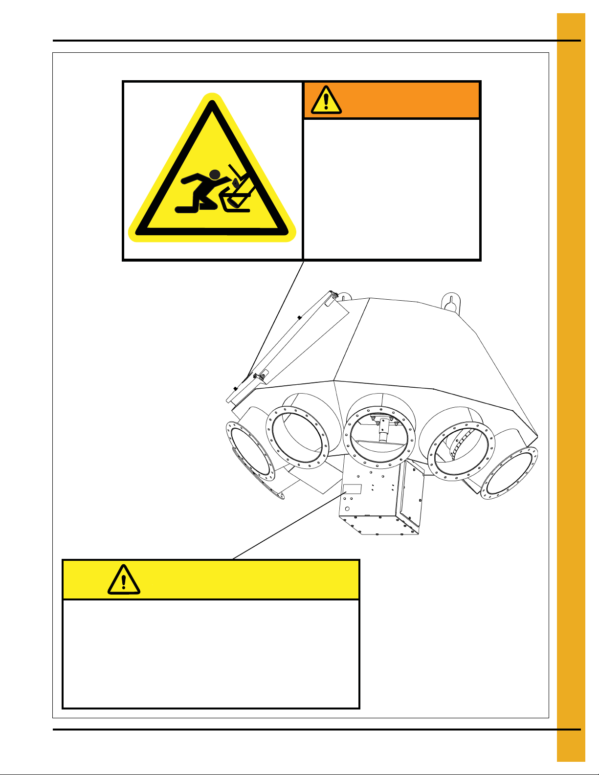
2. Decals
The decals are located as shown below:
DC-2159
WARNING
MOVING PARTS.
Rotating spout can
crush and cut.
Lock out power
before servicing.
CAUTION
Do not operate with access
panel removed.
Lock out power before servicing.
PNEG-1895 V2 Electronic Distributor Control 7
DC-2160
Page 8

3. Electrical Installation
Introduction
This section of the manual covers the electrical installation of your GSI electronically controlled distributor
and controller assembly. If your installation is an electronic controller retrofit being installed on an existing
GSI distributor, please begin with Section 6, Retrofit Installation on Page 40 and return to this section after
completion of mechanical component installation.
Wire and Fitting Selection Requirements
NOTE: The Sensor and VFD cables are supplied in 50' increments for a maximum length of 400'.
The Sensor cable has one unterminated end and one end has a connector. The VFD cable is
unterminated at both ends.
All sensor wiring should be run in its own conduit and this conduit should be kept at least 6" away from
other conduits. Any drain wires from shielded cable should be connected to ground in the panel.
VFD wiring should be run through appropriate conduit and the wiring for the motor must not be run in the
same conduit as the wiring for the sensors.
All conduit and fittings should be outdoor rated to keep things adequately sealed, rigid conduit
is required.
These shielding and conduit requirements must be followed for your GSI Electric Distributor Controller
to function properly. Failure to follow these guidelines may result in damage to equipment or
improper operation.
Figure 3A
8 PNEG-1895 V2 Electronic Distributor Control
Page 9
3. Electrical Installation
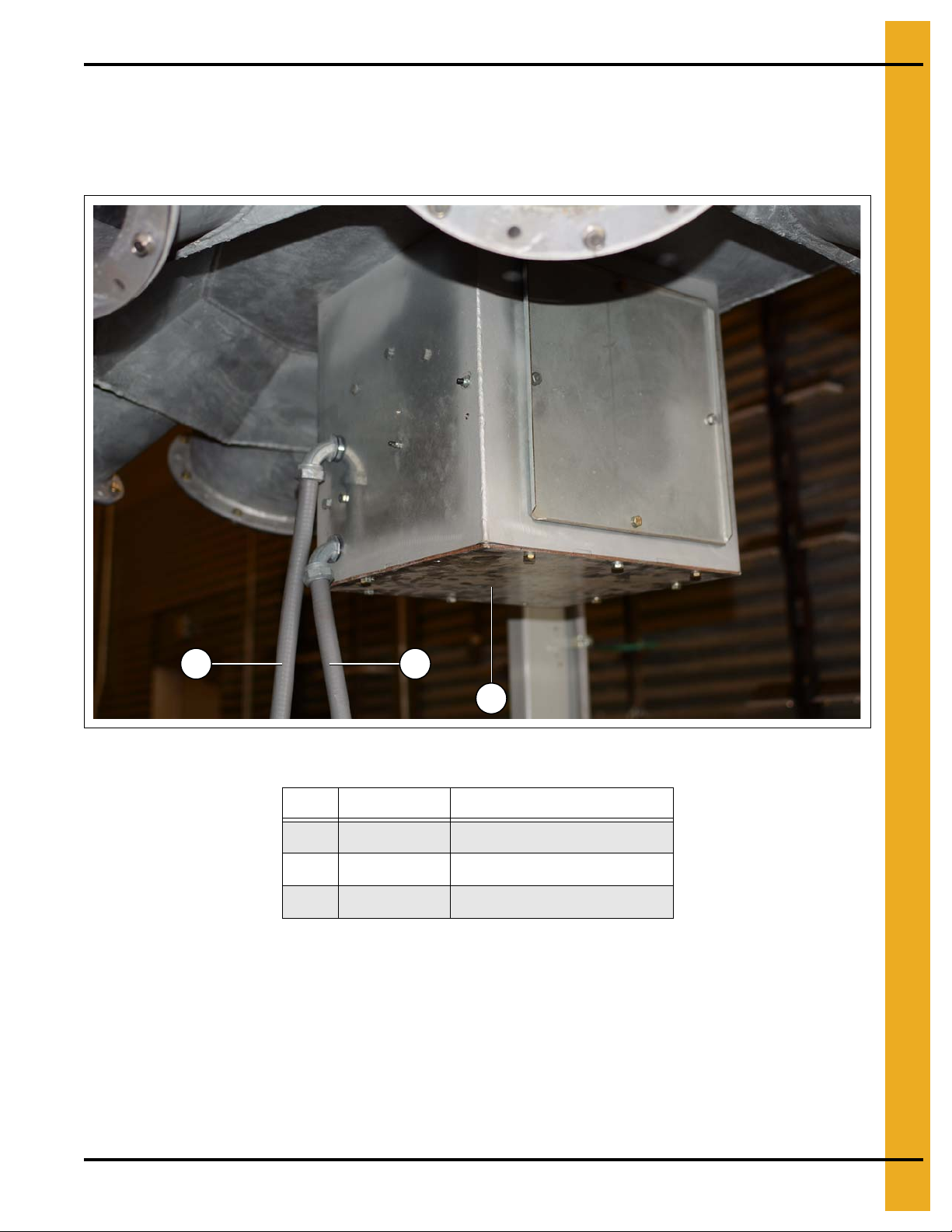
A
B B
Control Panel Cable to Distributor Fitting Connections
Conduit for motor wiring should be run out of enclosure (DEC0005) (A) to the panel installed at ground
level. Conduit for sensor wiring should be run from enc losure (DEC0005) (A) to pan el installed at ground
level. Appropriate fittings for conduit selection must be used at all connections. (See Figure 3B.)
Figure 3B Cable Fitting Connections to Distributor Enclosure
Ref # Part# Description
A DEC0005 Enclosure
B DEC0026-XXX Sensor Cable
B DEC0025-XXX VFD Cable
NOTE: “XXX” represents the length of the cable.
PNEG-1895 V2 Electronic Distributor Control 9
Page 10
3. Electrical Installation
A
B
C
D
Motor Cable to Motor Junction Box Fitting Connections
Remove the four (4) motor junction box cover screws (C) and the motor junction box cover (A) as shown
in Figure 3C.
Pull motor wiring through conduit to enclosure and feed to motor junction box (B) and through provided
cord grip. Motor wiring should be routed within the enclosure to avoid close proximity to all sensor wiring.
Motor wiring should be kept at least 4" from any sensor wires. (See Figure 3C.)
Figure 3C Cable fitting connection to motor junction box.
Ref # Description
A Motor Junction Box Cover
B Motor Junction Box
C Motor Junction Box Cover Screw
D Motor Cable
10 PNEG-1895 V2 Electronic Distributor Control
Page 11

3. Electrical Installation
Electric Motor Wiring Diagram
The electric motor supplied with the GSI Electronic Distributor Control system is designed to be capable
of running on either low or high voltage. The variable frequency drive (VFD) supplied with the system
supplies 230V 3 phase power and requires that the electric motor be configured for low volta ge operation.
In order to ensure proper operation, verify the motor jumpers are configured in accordance with the wiring
diagram shown for low voltage operation. (See Figure 3D.)
Figure 3D
PNEG-1895 V2 Electronic Distributor Control 11
Page 12
3. Electrical Installation
A
B
C
D
E
F
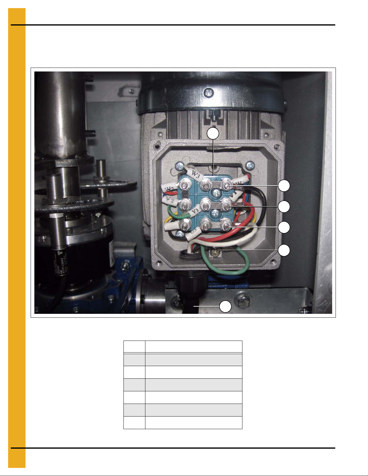
Motor Wiring Electrical Connections
Connect the motor wiring to the motor wiring terminals as shown in Figure 3E. Re-install the motor junction
box cover and screws before proceeding.
Figure 3E Motor Wiring to Motor Junction Box Electrical Connections
Ref # Description
A Motor Wiring Terminal Block
BWire W
C Wire V
DWire U
E Ground Wire
F Motor Cable
12 PNEG-1895 V2 Electronic Distributor Control
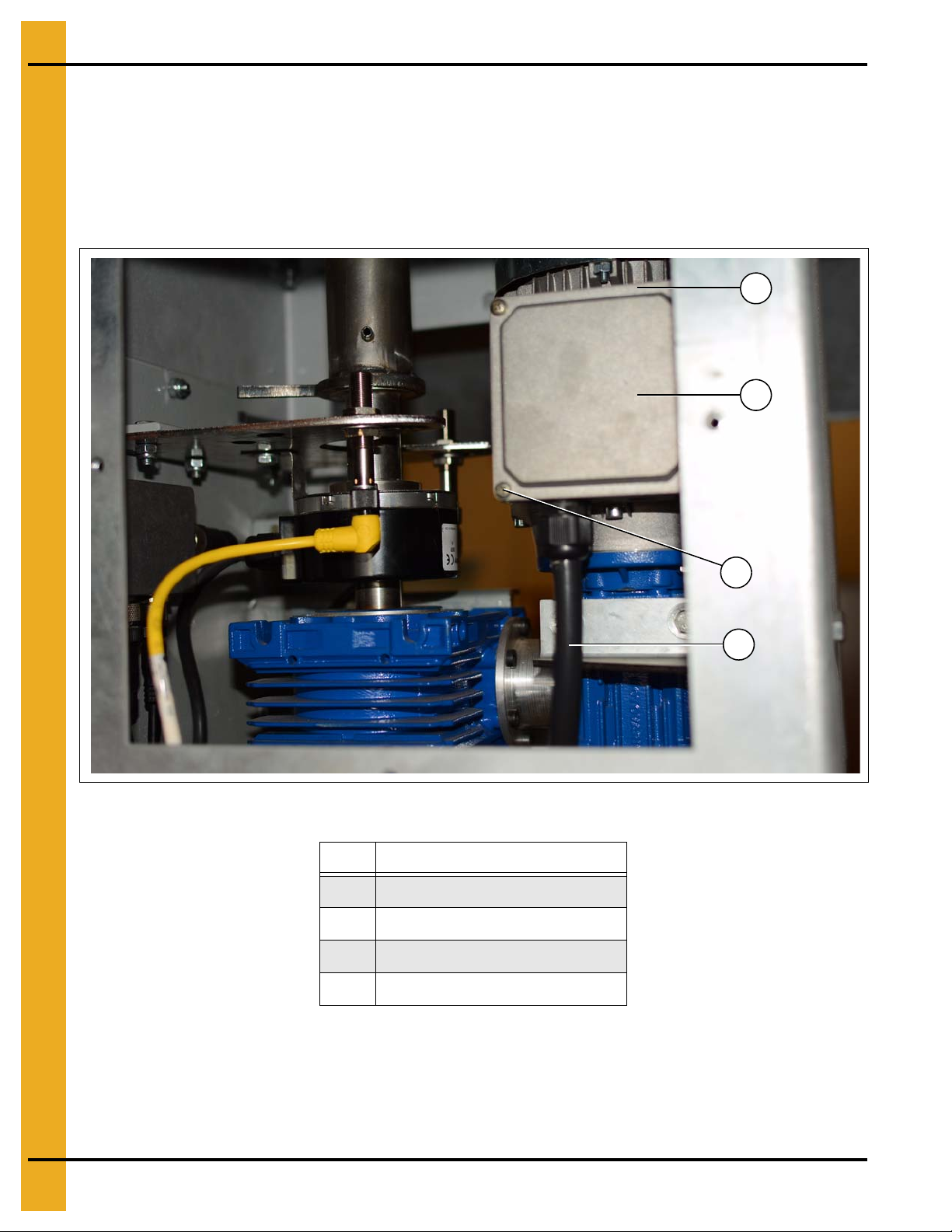
Page 13
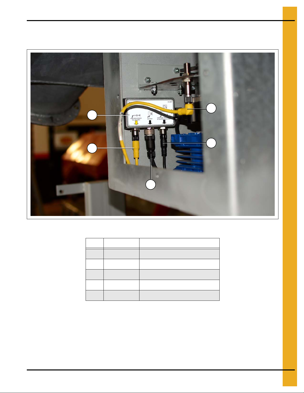
Sensor Wiring Connections to Connector Box
B
A
D
E
C
Pull sensor cable through conduit to enclosure. (See Figure 3F.)
3. Electrical Installation
Figure 3F Control Panel Wiring to Junction Box Electrical Connections
Ref # Part # Description
A DEC0108 Home Proximity Sensor Cable
B DEC0105 Connection Enclosure
C DEC0106 Encoder
D DEC0109 Over-Travel Proximity Sensor Cable
E DEC0026-XXX Sensor Cable
NOTE: “XXX” represent the length of the cable.
PNEG-1895 V2 Electronic Distributor Control 13
Page 14
3. Electrical Installation
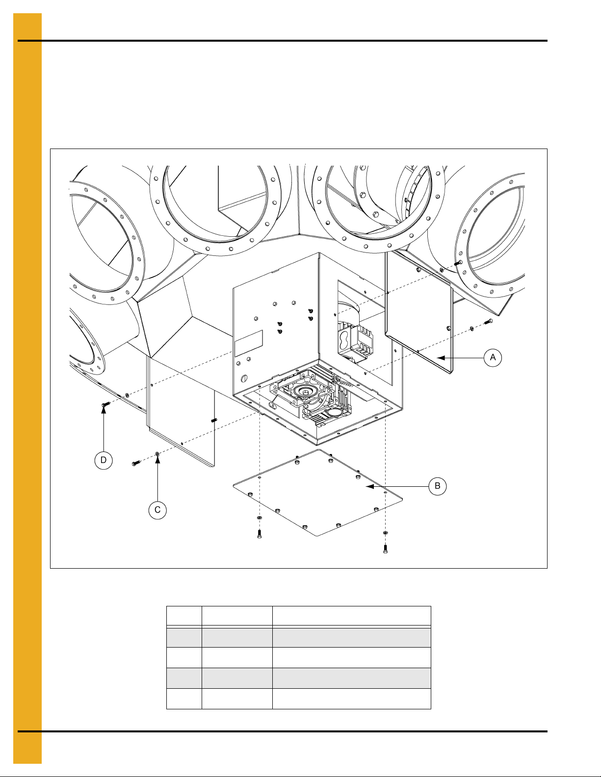
Enclosure Covers Installation
Once all wiring is complete, install the two (2) side access covers (DEC0012) (A) using four (4)
1/4"-20 x 3/4" HHCS bolts (S-1429) (D) and 1/4" lock washer (S-2041) (C) each and install the bottom
enclosure cover (DEC0013) (B) using ten (10) 1/4"-20 x 3/4" HHCS bolts (S-1429) (D) and 1/4" lock
washers (S-2041) (C) as shown in Figure 3G. Ensure that no wires are pinched or damaged when
installing access covers.
Figure 3G Enclosure Covers Installation
Ref # Part # Description
A DEC0012 Side Access Cover
B DEC0013 Bottom Enclosure Cover
C S-2041 1/4" Lock Washer
D S-1429 1/4"-20 x 3/4" HHCS Bolt
14 PNEG-1895 V2 Electronic Distributor Control
Page 15

3. Electrical Installation
Control Panel Installation Guidelines
The following requirements must be followed when installing and mounting the control panel:
All wiring should be performed by a licensed/qualified electrician in accordance with the National Electric
Code (NEC), state codes and local codes.
Never mount the control panel immediately beside or above heat generating equipment or directly below
water or steam pipes.
The atmosphere surrounding the control panel must be free of combustible vapors, chemical fumes and
corrosive materials.
The control panel must be easily accessible for maintenance and operation.
Mount the control panel on a flat, vertical surface using 1/4" fasteners.
Ensure that the mounting surface is sufficient to support the weight of the control panel.
Rigid conduit connections must be placed either at sides or bottom of the control panel.
PNEG-1895 V2 Electronic Distributor Control 15
Page 16
3. Electrical Installation
A
B
E
C
D
Electric Motor Connections at Control Panel
Connect the motor wiring to the terminals on the Variable Frequency Drive (VFD) in the control panel
as shown in Figure 3H. Please note that the U-V-W order of the wires is not configured as labeled on
the VFD. Motor wiring should be kept as far away from sensor wiring terminal blocks as the installation
configuration permits.
Figure 3H Control Panel Wiring from Motor Electrical Connections
Ref # Description
16 PNEG-1895 V2 Electronic Distributor Control
A Ground Terminal Block
BWire U
C Wire W
DWire V
E Ground Wire
Page 17
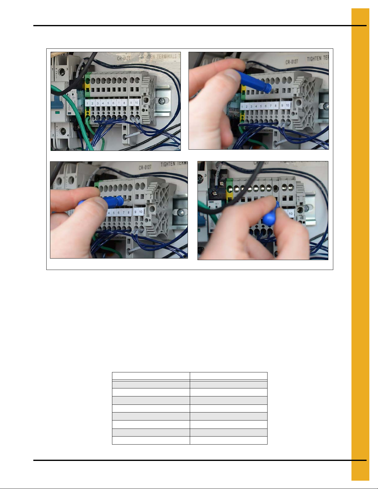
Sensor Terminations in Control Panel
1. Sensor terminal block
2. Push in screw driver
3. Push down on screw driver
4. Insert wire into open terminal
3. Electrical Installation
Figure 3I
Placing a wire into the terminal block.
NOTE: Insulation must be removed from the end of the wire for a good connection.
1. Insert a small screw driver into the square opening under the terminal.
2. Push down on the small screw driver.
3. Insert the wire into the open terminal block above the small screw driver.
4. Remove the small screw driver to secure the wire.
5. Repeat for remaining wires. (See Figure 3I.)
Wire Connections for Terminal Block
Terminal Block # Wire Connection
1 Shield
2Black
3 White
4Red
5 Green
6Orange
7 Blue
8-11 Used for Safety Interlocks
NOTE: #11 Not shown here.
PNEG-1895 V2 Electronic Distributor Control 17
Page 18

3. Electrical Installation
A
B
C
D
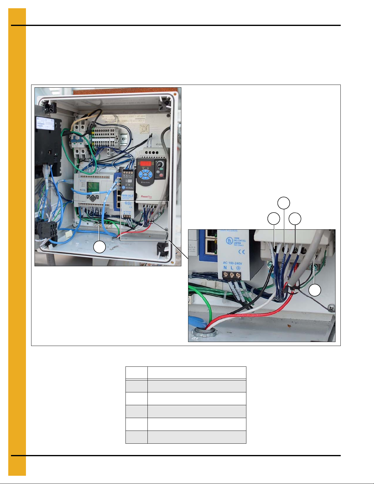
Power Supply Wiring to Control Panel Electrical Connections
NOTE: Ensure the power supply voltage source is OFF before installation.
Install power supply cable through the control panel using suitable hardware as shown in F igure 3J.
Connect the power supply hot wires (B) to the control panel circuit breakers (C) as shown in Figure 3J.
Connect the power supply ground wire (D) as shown in Figure 3J to the ground terminal block as shown
in Figure 3H on Page 16.
Figure 3J Control Panel Wiring from Motor Electrical Connections
Ref # Description
A Power Cable Hardware
BHot Wires
C Control Panel Circuit Breakers
D Power Supply Ground Wire
18 PNEG-1895 V2 Electronic Distributor Control
Page 19
4. Operation Procedures
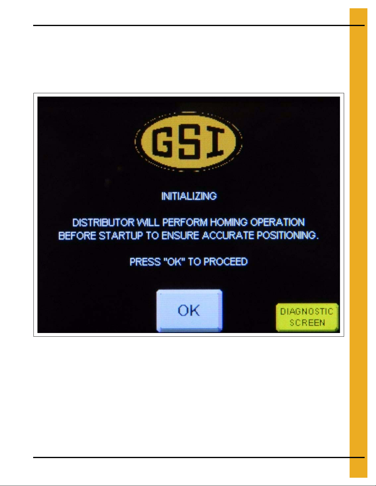
Initializing Screen
When powering up the distributor the first screen that appears is the “Initializing” screen. (See Figure 4A.)
During a first time start-up, press the “Diagnostic Screen” button to proceed to the diagnostic screen in
order to complete start-up checklist. If the start-up checklist has already been completed, press OK to
initialize system. Distributor will move to “HOME POSITION” to verify positioning, then display the
MAIN screen.
Figure 4A Initial Start-Up Screen
PNEG-1895 V2 Electronic Distributor Control 19
Page 20

4. Operation Procedures
Start-Up Checklist
Press “Diagnostic Screen” button to enter diagnostic menu to complete the following checklist:
Check Procedure
Insert key into key switch override on front of control panel. Rotate switch to forward “FWD” position
Motor Direction
Encoder Function
Home Prox Test
Overtravel Test
for 4 seconds. Verify that “DIRECTION” in bottom right hand corner reads “FORWARD” during this.
If “REVERSE” is displayed after 4 seconds, reverse any two (2) motor leads on motor or VFD to
correct rotation direction.
Using key switch, rotate switch to reverse “REV” position for 4 seconds. Verify that inputs 0 and 1.
(Labeled ENCODER CHANNEL A and ENCODER CHANNEL B in top left hand corner of screen.)
Toggle ON and OFF while switch is held in reverse position. If either channel fails to toggle ON or OFF ,
verify that encoder is wired correctly.
Using a second person as a spotter, use key switch to rotate spout in reverse direction until the “flag”
welded to the drive shaft is positioned over the top of the “home” proximity switch. (Located on side of
sensor mounting plate labeled “RED”.) Verify that when flag is positioned above proximity switch, input
2 labeled “HOME PROX SWITCH” turns green and shows “ON” on diagnostic screen. If input does not
show “ON”, check that gap between switch and flag is 0.050" ± 0.010".
Using a second person as a spotter, use key switch to rotate spout in forward direction until the “flag”
welded to the drive shaft is positioned over the top of the “overtravel” proximity switch. (Located on
side of sensor mounting plate labeled “GREY”.) Verify that when flag is positioned above proximity
switch, input 2 labeled “OVERTRAVEL PROX” turns green and shows “ON” on diagnostic screen.
If input does not show “ON”, check that gap between switch and flag is 0.050" ± 0.010".
Figure 4B Diagnostic Screen
20 PNEG-1895 V2 Electronic Distributor Control
Page 21

4. Operation Procedures
CURRENT SPOUT SELECTION:
BIN 1
CURRENT SPOUT SELECTION:
BIN 1
CURRENT SPOUT SELECTION:
BIN 1
CURRENT SPOUT SELECTION:
BIN 1
Main Screen
Depending on the number of spouts in the current configuration, one of the following screens will be
displayed. (See Figure 4C, Figure 4D, Figure 4E and Figure 4F.) The display depicts a view of your
distributor as it would appear if looking down from above, with lower spout numbers to the le ft and higher
spout numbers to the right. The name of the current spout is indicated at the top of the screen and is
indicated in the graphic with a green circle. At the bottom of the screen are three (3) buttons to navigate
to either the Help Menu, Move Position Screen or Setup Menu.
Figure 4C Four (4) Spout Main Screen
Figure 4D Six (6) Spout Main Screen
Figure 4E Eight (8) Spout Main Screen
Figure 4F Ten (10) Spout Main Screen
PNEG-1895 V2 Electronic Distributor Control 21
Page 22

4. Operation Procedures
Move Position Screen
This screen allows the user to change the distributor’s current spout position. The green highlig hted spout
number indicates the current selection. A spout number with a red circle with a line through it indicates a
position that is currently locked-out. (See “Position Lock-Out Screen” on Page 29.) (See Figure 4G.)
NOTE: The default names for each spout will be “BIN #”, see “Position Names Screen” on Page 25 for
instructions for customizing the spout names.
Figure 4G Move Position Screen
Moving Spout Position
1. On the “Move Position” screen, select the position you want the spout to move to by pressing the
button displaying the desired spout name on the screen.
2. The “Main Menu” screen will now display a flashing message “Moving to” at the top of the screen,
the selected spout number will flash yellow while the pointer is moving to the selected spout. The
destination spout number will turn green when the move is complete.
Verifying Spout Alignment
NOTE: In the following steps, the distributor must be in a position to view the spout location in the
distributor to verify that it lines up correctly. If the distributor is installed above ground level,
two (2) people will be needed; one to verify the alignment of the distributor spout and one to
operate the controller.
1. From the “Main” screen or the “Setup Menu”, select “MOVE” to view the “Move Position” screen.
(See Figure 4G.)
2. On the “Move Position” screen, select the position you want the spout to move to by pressing the
spout name on the screen.
3. The “Main Menu” screen will now display a flashing message “Moving to” at the top of the screen,
the selected spout number will flash yellow while the pointer is moving to the selected spout. The
destination spout number will turn green when the move is complete.
4. Once the spout has finished moving, visually check and verify the spout is centered with the
distributor discharge spout. If alignment requires adjustment, see “Position Locations Screen”
on Page 27 to adjust the positioning.
5. Repeat procedure for all other spouts.
22 PNEG-1895 V2 Electronic Distributor Control
Page 23

Setup Menu Screen
4. Operation Procedures
Figure 4H Setup Menu Screen
Configuration Setup: Displays the machine setup screen that allows the user to change the distributor’s
parameters or reload default values. See “Configuration Setup Screen” on Page 24.
Position Names: Allows the user to assign or change the name of each spout position and to create or
change a name for the distributor. See “Position Names Screen” on Page 25.
Position Locations: Displays the positioning screen which allows the user to set the value that aligns the
spouts with the distributor. See “Position Locations Screen” on Page 27.
Position Lock-Out: Allows the user to lock or unlock spouts from being used. See “Position Lock-Out
Screen” on Page 29.
Homing Interval: Allows the user to set the number of times before the “Perform Homing Now” warning
appears. See “Homing Interval Screen” on Page 30.
Perform Homing Now: Press this to perform the homing operation to re-calibrate the distributor.
PNEG-1895 V2 Electronic Distributor Control 23
Page 24

4. Operation Procedures
Configuration Setup Screen
This screen allows the user to change the distributor’s spout diameter property, total of number of spouts
and for resetting the distributor back to the default settings. (See Figure 4I.)
Figure 4I Configuration Setup Screen
Diameter of Spouts: Press the button that matches the size of the spout that is currently installed on the
distributor. The diameter that is selected will turn green and the number of spouts available for that
diameter will be displayed.
Number of Spouts: Press the button that matches the current configuration of the distributor. The number
that is selected will turn green. The number of spout options will change according to the diameter of
spout selected.
Reload Defaults: If during operation, any configuration par ameters are altered from the original settings,
pressing this button will revert settings to the default values.
OK: Press this button to save the current configuration and be brought back to the Setup Menu.
NOTE: A warning message will appear if distributor has already been previously configured.
(See Figure 4J.)
Figure 4J
24 PNEG-1895 V2 Electronic Distributor Control
Page 25

4. Operation Procedures
Position Names Screen
This screen allows the user to individually name each of the distributor discharge spouts and is also used
to create or modify a distributor name. (See Figure 4K.)
Figure 4K Create/Modify Spout Names
PNEG-1895 V2 Electronic Distributor Control 25
Page 26

4. Operation Procedures
Create/Modify Spout Name
1. From the “Setup Menu”, select “Position Names” to bring up the “Create/Modify Spout
Names” screen.
2. Press the spout name to be modified to display an alphanumeric keypad. (See Figure 4L.)
Figure 4L Alphanumeric Keypad
3. Type in the desired name for the spout position and press “enter”.
4. Select “OK” to return to “Setup Menu”.
Create/Modify Distributor Name
1. From the “Setup Menu”, select “Position Names” to bring up the “Create/Modify Spout
Names” screen.
2. Next to ochre “Distributor Name” label, press the distributor name to display an alphanumeric keypad.
(See Figure 4L.)
3. Type in the desired name for the spout position and press “enter”.
4. Select “OK” to return to “Setup Menu”.
26 PNEG-1895 V2 Electronic Distributor Control
Page 27

4. Operation Procedures
Position Locations Screen
This screen allows the user to adjust the spout positioning so it lines up with the center of the distributor
discharge. Adjustments can be made individually or an offset can be used to adjust all spouts by the same
amount. (See Figure 4M.)
Figure 4M Modify Spout Positioning
Modify Spout Positioning
1. From the “Setup Menu”, select “Position Locations” to bring up the “Modify Spout Positioning” screen.
2. In the “Modify Spout Positioning” screen select the spout that requires adjustment by touching the
value pad next to the spout number balloon. A number keypad will display. (See Figure 4N.)
Figure 4N Number Keypad
PNEG-1895 V2 Electronic Distributor Control 27
Page 28

4. Operation Procedures
3. Insert the desired value and press “enter”.
NOTE: Entering a value larger than the existing value will move spout positio n to the left, entering a
smaller value will move the position to the right.
4. Select “OK” to return to “Setup Menu”.
5. Verify spout alignment with distributor. See “Verifying Spout Alignment” on Page 22.
Offset All
1. From the “Setup Menu”, select “Position Locations” to bring up the “Modify Spout Positioning” screen.
2. In “Modify Spout Positioning” screen select the “0” key pad next to “OFFSET ALL”. A number keypad
will display. (See Figure 4O.)
Figure 4O Help Menu Screen
3. Insert the desired value and press “enter”.
To offset the spouts to the left, use a positive value and to offset to the right, use a negative value.
NOTE: A maximum offset at any one time is ± 20.
4. Select “OK” to return to “Setup Menu”.
5. Verify each spout alignment with distributor. See “Verifying Spout Alignment” on Page 22.
28 PNEG-1895 V2 Electronic Distributor Control
Page 29

4. Operation Procedures
Position Lock-Out Screen
The position lock-out allows you to lock-out a distributor discharge spout position so it can not be used
until it is manually unlocked. (See Figure 4P.)
Figure 4P Lock/Unlock Position
Lock/Unlock Position
1. From the “Setup Menu”, select “Position Lock-Out” to display the “Lock/Unlock Position”
setup screen.
2. Press name of spout to toggle between locked and unlocked. When in the locked position the number
balloon will change to a red circle with a line through it.
NOTE: The position that the distributor is currently located, indicated by a green number balloon
icon, can not be locked out. Move the spout position to a different location then try again.
See “Move Position Screen” on Page 22.
3. Select “OK” to apply changes and return to “Main Menu”.
PNEG-1895 V2 Electronic Distributor Control 29
Page 30

4. Operation Procedures
Homing Interval Screen
The homing interval screen allows the user to set the number of times the distributor position may be
moved before a warning displays for home position re-calibration. A default value of 50 is standard.
(See Figure 4Q.)
Figure 4Q Homing Interval Screen
Setting Homing Interval
1. To access the homing interval from the “Setup Menu”, select “Homing Interval” to display the “Homing
Interval” setup screen.
2. Press the button under the “Homing Interval” label. A number keypad will display. (See Figure 4R.)
Figure 4R
3. Insert the desired value and press “enter”.
4. Select “OK” to apply changes and return to “Main Menu”.
30 PNEG-1895 V2 Electronic Distributor Control
Page 31

4. Operation Procedures
Homing Warning
To help ensure accurate positioning of the distributor a homing warning will display when the number of
times the distributor is re-positioned is equal to the homing interval. This message will occur every time
that a spout move is attempted until the homing procedure is completed. The user will be given two (2)
options: “Home Now” and “Home Next Move”. (See Figure 4S.)
Figure 4S Homing Warning
Home Now
Select to perform the homing calibration immediately. The user interface will return to the “MAIN”
screen and “Homing” will be shown in yellow. After homing is complete, the spout will return to the
selected position.
Home Next Move
Select “Home Next Move” to skip the homing operation and move to the selected position. The user
interface will continue to prompt you to home the unit during every subsequent move until homing
is performed.
PNEG-1895 V2 Electronic Distributor Control 31
Page 32

4. Operation Procedures
Help Menu Screen
The help menu has six (6) options for displaying troubleshooting information for different faults that may
appear during the operation of the distributor and for checking diagnostic parameters. (See Figure 4T.)
Figure 4T Help Menu Screen
Encoder Fault: Displays the “Encoder Fault” screen which displays fault codes and solutions for faults
related to the function of the encoder during movement. (See Figure 4U on Page 33.)
Drive Fault: Displays the “VFD” Fault screen which offers pos sible causes and solutions to f aults caused
by the variable frequency drive. (See Figure 4V on Page 33.)
Homing Fault: Displays the “Homing Fault” screen which offers possible causes and solutions to faults
caused by a timeout of the homing procedure. (See Figure 4W on Page 34.)
Overtravel Fault: Displays the “Overtravel Fault” screen which offers possible causes and solutions to
faults caused by the an overtravel condition. (See Figure 4X on Page 34.)
Direction Fault: Displays the “Direction Fault” screen which offers possible causes and solu tions to faults
caused by the detection of a rotation direction conflict. (See Figure 4Y on Page 35.)
Diagnostic Screen: Displays the status of the inputs and outputs of the Programmable Logic Controller
(PLC) as well as the current encoder position count and rotation direction. (See Figure 4Z on Page 35.)
32 PNEG-1895 V2 Electronic Distributor Control
Page 33

Encoder Fault Screen
4. Operation Procedures
Drive Fault Screen
Figure 4U Encoder Fault Screen
Figure 4V Drive Fault Screen
PNEG-1895 V2 Electronic Distributor Control 33
Page 34

4. Operation Procedures
Homing Fault Screen
Overtravel Fault Screen
Figure 4W Homing Fault Screen
Figure 4X Overtravel Fault Screen
34 PNEG-1895 V2 Electronic Distributor Control
Page 35

Direction Fault Screen
4. Operation Procedures
Diagnostic Screen
Figure 4Y Direction Fault Screen
Figure 4Z Diagnostic Screen
PNEG-1895 V2 Electronic Distributor Control 35
Page 36

4. Operation Procedures
A
Manual Override
Located on the front of the controller is a manual/jog dial (A). This manual override is key locked and
should only be used in case of a major equipment failure. It allows for manually moving the spout in the
direction you turn the dial when the key is inserted.
It is recommended that two (2) people perform this procedure. One person to operate the manual/jog
dial (A) and another to look through the distributor and verify alignment of the spout. (See Figure 4AA.)
NOTE: Panel will not close with key inserted in the manual/jog dial (A). Always keep key in a safe location
for access by authorized personnel only.
Figure 4AA
Ref # Description
36 PNEG-1895 V2 Electronic Distributor Control
A Manual/Jog Dial
Page 37

NOTES
PNEG-1895 V2 Electronic Distributor Control 37
Page 38

5. Parts List
Assembly Procedure:
1. Install shaft (DEC0009) with provided roll
pins (S-9288).
2. Install enclosure (DEC0005) with 3/8" bolts and
nylock nuts.
3. Install junction box (DEC0105) with self-drilling
screws.
4. Install sensor mounting angle (DEC0014) and
plate (DEC0006).
5. Install sensors (DEC0107) and set clearance.
(See detail A.)
6. Install encoder (DEC0106), torque set screw to
8 in-lbs.
7. Install motor (DEC0015) and mount brackets
(DEC0003 and DEC0021).
8. Install bottom (DEC0021) and side (DEC0013)
covers.
NOTE: Install sensors in #3 hole on both sides.
Set 0.050" ± 0.01" clearance from face of each
sensor to flag on shaft.
See detail A
Detail A
12" 6 Hole 45° Distributor Assembly Electronic Control
(DFB12645G-EC)
38 PNEG-1895 V2 Electronic Distributor Control
Page 39

5. Parts List
12" 6 Hole 45° Distributor Assembly Electronic Control (DFB12645G-EC) Parts List
Ref # Part # Description Qty
1 DFB12645G 12" 6 Hole 45° Distributor Assembly 1
2 DEC0009 Weldment, Shaft and Flag, 1/2 HP Distributor Control 1
3 DEC0005 Weldment, Enclosure, 1/2 HP Distributor Control 1
4 DEC0014 Angle, Sensor Plate Mounting, 1/2 HP Distributor Control 1
5 DEC0006 Bracket, Proximity Sensor, 1/2 HP Distributor Control 1
6 DEC0015 Gear Motor, DBL WRM, 1/2 HP, 400:1, Distributor Control 1
7 DEC0003 Bracke t, Motor Mount, 1/2 HP Distributor Control 1
8 DEC0016 Bracket, Encoder Mount, Distri butor Control 1
9 DEC0106 Encoder, with Connector 2048 PPR, 30 mm, Distributor Control 1
10 DEC0107 Sensor, Prox, Threaded, Inductive, 12 mm, S=4 2 2
11 DEC0105 Connector Box, Farm Distributor Control 1
12 DEC0013 Cover, Side Access, 1/2 HP Distributor Control 2
13 DEC0012 Cover, Enclosure Bottom, 1/2 HP Distributor Control 1
14 S-2041 Split Lock Washer 1/4" ZN 18
15 S-1429 Bolt, HHCS 1/4"-20 x 3/4" ZN Grade 2 29
16 S-2126 Flat Washer 1/4" x 2-5/8" SAE ZN Grade 2 11
17 S-6998 Bolt, HHCS 1/4"-20 x 1" ZN Grade 5 4
18 S-7025 Nylock Nut 1/4"-20 ZN Grade 5 15
19 S-9288 Spring Pin 1/4" x 2-1/2" Plain Steel Slotted Rolled 2
20 S-7469 Bolt, HHCS 3/8"-16 x 1" ZN Grade 5 5
21 S-7383 Nylock Nut 3/8"-16 ZN Grade 5 4
22 S-10200 Fender Washer 3/8" x 1-1/2" O.D. ZN 1
23 S-7223 Split Lock Washer #10 ZN 3
24 S-10167 Bolt, SHCS #10-32 x 1/4" ZN 3
25 DEC0021 Bracket, Motor Mount Short, 1/2 HP Distributor Control 1
26 DC-2160 Decal, Caution, Do not Operate with Access Panel 1
27 DC-2159 Decal, Warning, Rotating Spout can Crush and Cut 1
28 DEC0108 Cable, Home Proximity Sensor Cable Yellow 1
29 DEC0109 Cable, Overtravel Proximity Sensor Cable Black 1
30 DEC0011 Key, 1/4" x 3" L 1
N/S DEC0110 Panel, V2 Electric Distributor Control 1
N/S PNEG-1895 Manual, V2 Distributor Electric Control 1
PNEG-1895 V2 Electronic Distributor Control 39
Page 40

6. Retrofit Installation
Electronic Distributor Control Shaft Installation
Install the shaft (DEC0009) (A) to the distributor shaft (D) using two (2) roll pins (S-9288) (B). NOTE: Flag
extension (C) should be installed in line with the spout to ensure proper alignment with the sensor.
(See Figure 6A.)
Figure 6A Electronic Distributor Control Shaft
Ref # Part # Description
A DEC0009 Shaft
B S-9288 Roll Pin
C Flag Extension
D Distributor Shaft
E Spout
40 PNEG-1895 V2 Electronic Distributor Control
Page 41

6. Retrofit Installation
Electronic Distributor Enclosure Installation
Install the enclosure (DEC0005) to the distributor (C) using four (4) 3/8 bolts (S-7469) (B) and nylock nuts
(S-7383) (A). (See Figure 6B.) Note the orientation of the enclosure; the side with th e two (2) large holes
must face away from back wall of distributor. Controller will not work if installed backwards.
Figure 6B Electronic Distributor Enclosure
Ref # Part # Description
A S-7383 3/8" Nylock Nut
B S-7469 3/8" Bolt
C Distributor
PNEG-1895 V2 Electronic Distributor Control 41
Page 42

6. Retrofit Installation
Sensor Plate Angle and Proximity Sensor Bracket Installation
Assemble the sensor plate angle (DEC0014) (A) to the proximity sensor bracket (DEC0006) (D) using
three (3) 1/4"-20 x 3/4" HHCS bolts (S-1429) (B) and 1/4"-20 nylock nuts (S-7025) (C) as shown in
Figure 6C.
Attach the proximity sensor bracket (DEC0006) (D) to the inside of the enclosure (DEC0005) (E) using
three (3) 1/4"-20 x 3/4" HHCS bolts (S-1429) (B) and 1/4"-20 nylock nuts (S-7025) (C). (See Figure 6C.)
Bracket must be installed with note markings facing down.
Figure 6C Sensor Plate Angle and Proximity Sensor Bracket
Ref # Part # Description
A DEC0014 Sensor Plate Angle
B S-1429 1/4"-20 x 3/4" HHCS Bolt
C S-7025 1/4"-20 Nylock Nut
D DEC0006 Proximity Sensor Bracket
E DEC0005 Enclosure
42 PNEG-1895 V2 Electronic Distributor Control
Page 43

6. Retrofit Installation
Diameter # Spouts Prox Ref #
6
4 2
65
8 6
8
65
8 7
10 9
10
6 4
810
10 9
12
41
6 3
88
10 9
14
41
6 3
8 8
Proximity Sensor Location and Installation
NOTE: The location of the proximity sensor will be determined by the configuration of the distributor.
Using the table shown in Figure 6D, locate the diameter and number of spouts of the distributor being
used and note the proximity sensor reference number. This reference number is marked on the bottom
of the proximity sensor bracket (DEC0006) (B) and identifies the location for installing the proximity
sensors (DEC0107) (A).
Install the two (2) proximity sensors (DEC0107) (A) into the proximity sensor bracket (DEC0006) (B) at the
appropriate locations determined from the table. (See Figure 6D below and Figure 6E on Page 44.)
PNEG-1895 V2 Electronic Distributor Control 43
Figure 6D Proximity Sensor Location
Ref # Part # Description
A DEC0107 Proximity Sensor
B DEC0006 Proximity Sensor Bracket
Page 44

6. Retrofit Installation
Proximity Sensor Location and Installation (Continued)
Figure 6E Proximity Sensor Installation
Ref # Part # Description
A DEC0107 Proximity Sensor
B DEC0006 Proximity Sensor Bracket
44 PNEG-1895 V2 Electronic Distributor Control
Page 45

6. Retrofit Installation
Proximity Sensor Adjustment
Set the clearance of the two (2) proximity sensors (DEC0107) (A) to 0.050" ± 0.01" from the face of each
sensor to the flag (B) on the shaft (DEC0009). (See Figure 6F.) This adjustment may need to be made
after motor is wired by using manual key switch to locate flag above each proximity sensor.
Figure 6F Proximity Sensor Adjustment
Ref # Part # Description
A DEC0107 Proximity Sensor
BFlag
PNEG-1895 V2 Electronic Distributor Control 45
Page 46

6. Retrofit Installation
Encoder and Bracket Installation
Install the encoder (DEC0106) (A) to the encoder mounting bracket (DEC0016) (B) using the three (3)
#10-32 bolts (S-10167) (D) and #10 washers (S-7223) (C) as shown in Figure 6G.
Tighten the encoder collar set screw (E) as shown in Figure 6H on Page 47 to 8 in-lbs.
Install the encoder mounting bracket (DEC0016) (B) to the proximity sensor bracket (DEC0006) (H) using
the 1/4"-20 x 3/4" HHCS bolt (S-1429) (I), 1/4" washer (S-2126) (J) and 1/4"-20 nylock nut (S-7025) (K) as
shown in Figure 6I on Page 48.
Figure 6G Encoder to Mounting Bracket
Ref # Part # Description
A DEC0106 Encoder
B DEC0016 Encoder Mounting Bracket
C S-7223 #10 Washer
D S-10167 #10-32 Bolt
46 PNEG-1895 V2 Electronic Distributor Control
Page 47

Encoder and Bracket Installation (Continued)
6. Retrofit Installation
Figure 6H Encoder Collar Set Screw
Ref # Part # Description
A DEC0106 Encoder
E Encoder Collar Set Screw
F Encoder Collar
PNEG-1895 V2 Electronic Distributor Control 47
Page 48

6. Retrofit Installation
Encoder and Bracket Installation (Continued)
Figure 6I Connector Box Install, Sensor Connectors to Encoder Connection
Ref # Part # Description
B DEC0016 Encoder Mounting Bracket
G DEC0107 Proximity Sensor
H DEC0006 Proximity Sensor Bracket
I S-1429 1/4"-20 x 3/4" HHCS Bolt
J S-2126 1/4" Washer
K S-7025 1/4"-20 Nylock Nut
48 PNEG-1895 V2 Electronic Distributor Control
Page 49

6. Retrofit Installation
E
D
G
H
F
Installing the Connector Box and Cables
1. Install the connector box to the inside of the enclosure using four (4) bolts (B) and nuts (C).
Make sure nuts are located on the outside of the enclosure. (See Figure 6J.)
Figure 6J
2. Pull sensor cable through the conduit connected to the enclosure.
3. Connect cables to the connector enclosure. (See Figure 6K.)
Figure 6K Control Panel Wiring to Junction Box Electrical Connec tio ns
Ref # Part # Description Ref # Part # Description
A Enclosure E DEC0105 Connection Enclosure
BBolts
C Nuts G DEC0109 Over-Travel Proximity Sensor Cable
D DEC0108 Home Proximity Sensor Cable
NOTE: “XXX” represent the length of the cable.
PNEG-1895 V2 Electronic Distributor Control 49
F DEC0106 Encoder
H DEC0026-XXX Sensor Cable
Page 50

6. Retrofit Installation
Motor Mounting Bracket Installation
Install the motor mounting bracket (DEC0003) (A) to the enclosure (DEC0005) (E) using two (2)
1/4"-20 x 3/4" HHCS bolts (S-1429) (D), 1/4" washers (S-2126) (C) and 1/4"-20 nylock nuts (S-7025) (B)
as shown in Figure 6L.
Figure 6L Motor Mounting Bracket
Ref # Part # Description
A DEC0003 Motor Mounting Bracket
B S-7025 1/4"-20 Nylock Nut
C S-2126 1/4" Washer
D S-1429 1/4"-20 x 3/4" HHCS Bolt
E DEC0005 Enclosure
50 PNEG-1895 V2 Electronic Distributor Control
Page 51

6. Retrofit Installation
Control Motor Installation
Install the motor (DEC0015) (A) to the motor mounting bracket (DEC0003) (F) using two (2) 1/4"-20 x 1"
HHCS bolts (S-6998), four (4) 1/4" washers (S-2126) (D) and two (2) 1/4"-20 nylock nuts (S-7025) (C) as
shown in Figure 6M.
Install second motor mounting bracket (DEC0021) (B) to the enclosure (DEC0005) using two (2)
1/4"-20 x 3/4" HHCS bolts (S-1429) (E), 1/4" washers (S-2126) (D) and 1/4"-20 nylock nuts (S-7025) (C).
Then install the motor to the motor mounting bracket (DEC0021) (B) using two (2) 1/4"-20 x 1" HHCS
bolts (S-6998), four (4) 1/4" washers (S-2126) (D) and two (2) 1/4"-20 nylock nuts (S-7025) (C) as shown
in Figure 6M.
Figure 6M Control Motor Installation
Ref # Part # Description
A DEC0015 Motor
B DEC0021 Motor Mounting Bracket - Short
C S-7025 1/4"-20 Nylock Nut
D S-2126 1/4" Washers
E S-1429 1/4"-20 x 1" HHCS Bolt
F DEC0003 Motor Mounting Bracket
G DEC0011 Key
PNEG-1895 V2 Electronic Distributor Control 51
Page 52

7. Troubleshooting
Error Messages
Figure 7A
Cause: When using the supplied interlock function, this message will appear when a move is attempted
while the contact closure that indicates that upstream equipment is running is closed. The move will
complete once the contact closure opens indicating the upstream equipment is no longer running.
Figure 7B
Cause: This message will appear if the user attempts to move to the position where the distributor is
currently located. If a different position is desired, the user must select a different position.
Figure 7C
Cause: This message will appear if the user attempts to move to a position that has been configured as
“locked-out.” If this position is desired, it must first be unlocked by navigating to “Position Lock-Out” screen
in the setup menu.
52 PNEG-1895 V2 Electronic Distributor Control
Page 53

7. Troubleshooting
Figure 7D
Cause: This message will appear if the user attempts to enter a po sition location value that is outside the
range of values allowed by the controller. This range exists to protect the equipment. To prevent this
message, user should enter a value that is within the range of values displayed in the error message.
(These values will vary for each controller; the values shown in Figure 7D will not be representative of
all configurations.)
Figure 7E
Cause: This message will appear if the controller has sensed that the spout has drifted from its desired
position while not being commanded to move. This may be caused by mechanical lash within the drive
mechanism or by the use of the manual key switch override on the front of the panel. User should execute
a “Move” command (see moving positions on Page 22) before attempting to move material through
distributor. Controller should force a homing operation before completing the move command.
Figure 7F
Cause: This message will be displayed if the user attempts to select the position where the distributor is
currently located to be locked-out. If this position is desired for lock-out, a “Move” command (see mo ving
positions on Page 22) should be performed to change to another position before selecting the position
for lock-out.
PNEG-1895 V2 Electronic Distributor Control 53
Page 54

7. Troubleshooting
Fault Code Descriptions, Possible Causes and Solutions
Code Fault Type Description Cause Solution
Using manual key switch, verify that forward command
produces counter-clockwise (as observed from above)
101 Direction
102 Direction
201 Encoder
Motor Direction
Forward, Encoder
Reading Reverse
Motor Direction
Reverse, Encoder
Reading Forward
Encoder Channel A
is OFF, Encoder
Channel B is OFF
Motor wiring or
encoder signal
wiring is reversed.
Motor wiring or
encoder signal
wiring is reversed.
Controller is
detecting no signal
from encoder
channel A or
encoder channel B.
distributor rotation. If distributor rotates clockwise (as
observed from above), swap any two (2) motor leads to
reverse motor rotation direction. If motor direction is
correct, check blue terminals 3 and 4 for correct wiring
both at junction box and control panel.
Using manual key switch, verify that forward command
produces counter-clockwise (as observed from above)
distributor rotation. If distributor rotates clockwise (as
observed from above), swap any two (2) motor leads to
reverse motor rotation direction. If motor direction is
correct, check blue terminals 3 and 4 for correct wiring
both at junction box and control panel.
Verify encoder wiring per instructions in this manual.
Encoder connections are blue terminal blocks. Blue
terminal block #1 should be connected to red encoder
wire. Blue terminal block #2 should be connected to
blue encoder wire. Blue terminal block #3 should be
connected to pink encoder wire. Blue terminal block #4
should be connected to white encoder wire.
202 Encoder
203 Encoder
204 Encoder
Encoder Channel A
is OFF, Encoder
Channel B is ON
Encoder Channel A
is ON, Encoder
Channel B is OFF
Encoder Channel A
is ON, Encoder
Channel B is ON
Controller is
detecting no signal
from encoder
channel A,
channel B is always
ON.
Controller is
detecting encoder
channel A always
ON, channel B no
signal.
Controller is
detecting encoder
channel A and
channel B always
ON.
Controller is receiving no signal from channel A (blue
terminal block #3) and a constant signal from channel B
(blue terminal block #4). Verify encoder wiring as
referenced above and ensure all terminal blocks are
secure with proper electrical continuity. If wiring is
correct and all terminals have continuity, check for 24V
across terminals 1 and 2. If encoder has 24V power
and problem persists the encoder has likely failed.
Replace encoder.
Controller is receiving a constant signal from channel A
(blue terminal block #3) and no signal from channel B
(blue terminal block #4). Verify encoder wiring as
referenced above and ensure all terminal blocks are
secure with proper electrical continuity. If wiring is
correct and all terminals have continuity, check for 24V
across terminals 1 and 2. If encoder has 24V power
and problem persists the encoder has likely failed.
Replace encoder.
Controller is receiving a constant signal from channel A
(blue terminal block #3) and a constant signal from
channel b (blue terminal block #4). Verify that encoder
ground (blue terminal block #2) is secure with proper
electrical continuity at all terminations. If wiring is
correct and all terminals have continuity, check for 24V
across terminals 1 and 2. If encoder has 24V power
and problem persists the encoder has likely failed.
Replace encoder.
54 PNEG-1895 V2 Electronic Distributor Control
Page 55

7. Troubleshooting
Fault Code Descriptions, Possible Causes and Solutions
(Continued)
Code Fault Type Description Cause Solution
Controller is receiving no signal from channel A (blue
terminal block #3) and a normal pulsing signal from
channel B (blue terminal block #4). Verify that blue
terminal block #3 has proper electrical continuity and
that connections are secure. If wiring is correct and
all terminals have continuity, check for 24V across
terminals 1 and 2. If encoder has 24V power and
problem persists the encoder has likely failed.
Replace encoder.
Controller is receiving a constant signal from
channel A (blue terminal block #3) and a normal
pulsing signal from channel B (blue terminal block #4).
Verify that blue terminal block #3 has no short present
in that circuit and that connections are secure. If wiring
is correct and all terminals have continuity, check for
24V across terminals 1 and 2. If encoder has 24V
power and problem persists the encoder has likely
failed. Replace encoder.
205 Encoder
206 Encoder
Encoder Channel A
is OFF, Encoder
Channel B is OK
Encoder Channel A
is ON, Encoder
Channel B is OK
Controller is detecting no
signal from encoder
channel A, channel B is
functioning normally.
Controller is detecting
encoder channel A
always ON, channel B
is functioning normally.
207 Encoder
208 Encoder
301 VFD
Encoder Channel A
is OK, Encoder
Channel B is OFF
Encoder Channel A
is OK, Encoder
Channel B is ON
Variable frequency
electric motor drive
has faulted.
Controller is detecting
encoder channel A
functioning normally,
channel B no signal.
Controller is detecting
encoder channel A
functioning normally,
channel B always ON.
VFD has detected a
malfunction while driving
the electric motor.
Controller is receiving a normal pulsing signal from
channel A (blue terminal block #3) and no signal from
channel B (blue terminal block #4). Verify that blue
terminal block #4 has proper electrical continuity and
that connections are secure. If wiring is correct and
all terminals have continuity, check for 24V across
terminals 1 and 2. If encoder has 24V power and
problem persists the encoder has likely failed.
Replace encoder.
Controller is receiving a normal pulsing signal from
channel A (blue terminal block #3) and a constant
signal from channel B (blue terminal block #4). Verify
that blue terminal block #4 has no short present in that
circuit and that connections are secure. If wiring is
correct and all terminals have continuity, check for 24V
across terminals 1 and 2. If encoder has 24V power
and problem persists the encoder has likely failed.
Replace encoder.
Open control panel and observe red LCD display
screen on power flex Variable Frequency Drive (VFD).
this display should show a numbered fault code
corresponding to the malfunction. Press red button
to reset fault and consult manufacturer’s technical
manual for full description of fault.
PNEG-1895 V2 Electronic Distributor Control 55
Page 56

7. Troubleshooting
Fault Code Descriptions, Possible Causes and Solutions
(Continued)
Code Fault Type Description Cause Solution
Controller has received a signal from proximity sensor
on home side of assembly (noted as “red” on sensor
mounting plate and run to red terminal blocks) during a
position move, indicating spout has overtraveled
expected position. Verify that proximity sensors are
401 Overtravel
402 Overtravel
Overtravel left
(home side)
detected during
position move.
Overtravel right
detected during
position move.
Controller has detected
signal indicating spout
has traveled past position
#1 toward back wall.
Controller has detected
signal indicating spout
has traveled past last
position toward back wall.
in correct numbered positions on mounting plate
(See Page 43), are wired to the correct terminal blocks
and that no metal objects are within 2 mm (0.080") of
the black plastic sensing surface. Metal flag welded to
shaft should only pass over home proximity sensor
during a homing procedure. Flag should trigger
proximity sensor after passing position #1 toward back
wall of distributor, just before internal spout makes
contact with back wall.
Controller has received a signal from proximity sensor
on far side of assembly (noted as “grey” on sensor
mounting plate and run to grey terminal blocks)
during a position move, indicating spout has
overtraveled expected position. Verify that proximity
sensors are in correct numbered positions on
mounting plate (See Page 43), are wired to the correct
terminal blocks and that no metal objects are within
2 mm (0.080") of the black plastic sensing surface.
Metal flag welded to shaft should never pass over
overtravel proximity sensor during normal operation.
Flag should trigger sensor only if spout has traveled
past the last position.
501 Encoder
601 Encoder
Homing operation
has timed out
before completion.
System has
detected a change
in position without
a move command
from PLC.
Controller did not receive
signal from home
proximity sensor within
the maximum allowable
time limit.
Controller has measured
movement of spout
assembly without user
input. This may be caused
by use of the manual/key
switch override or by other
mechanical issue.
Homing operation rotates distributor spout to a
position between the back wall of the distributor and
the center of the #1 position to set a constant zero
point. If controller does not receive signal from home
proximity sensor within a pre-defined time limit,
homing operation fails. this may be caused by a
mechanical obstacle stopping rotation or by the
sensor not being triggered by the metal flag welded
to the drive shaft. If the gap between the proximity
sensor and the flag welded to the drive shaft is too
large, the sensor will not trigger and homing will fail.
Verify that the gap between sensor and flag is
0.050" ± 0.010". Manual key switch may be used to
check this. If gap is correct and red LED light on
sensor illuminates in presence of shaft flag, verify that
the sensor is wired to the correct red terminal blocks,
and that diagnostic screen shows home prox “on”
when flag is over top of sensor.
If fault is caused by use of key switch, distributor may
be returned to a position by performing a “move”
command from move screen. Distributor will force a
homing operation before completing move command
to ensure accurate positioning. Controller should
return spout to the selected position on completion
of homing.
56 PNEG-1895 V2 Electronic Distributor Control
Page 57

White Panel Layout
8. Schematic and Wiring Diagrams
Figure 8A
PNEG-1895 V2 Electronic Distributor Control 57
Page 58

8. Schematic and Wiring Diagrams
White Panel Electrical Schematic
Figure 8B
58 PNEG-1895 V2 Electronic Distributor Control
Page 59

8. Schematic and Wiring Diagrams
White Panel Electrical Schematic (Continued)
Figure 8C
PNEG-1895 V2 Electronic Distributor Control 59
Page 60

NOTES
60 PNEG-1895 V2 Electronic Distributor Control
Page 61

9. Warranty
9101239_1_CR_rev7.DOC (revised July 2009)
GSI Group, LLC Limited Warranty
The GSI Group, LLC (“GSI”) warrants products which it manufactures to be free of defects in materials and workmanship
under normal usage and conditions for a period of 12 months after sale to the original end-user or if a foreign sale,
14 months from arrival at port of discharge, whichever is earlier. The end-user’s sole remedy (and GSI’s only obligation)
is to repair or replace, at GSI’s option and expense, products that in GSI’s judgment, contain a material defect in materials
or workmanship. Expenses incurred by or on behalf of the end-user without prior written authorization from the GSI
Warranty Group shall be the sole responsibility of the end-user.
Warranty Extensions:
The Limited Warranty period is extended for the following products:
Product Warranty Period
Performer Series Direct Drive Fan Motor 3 Years
AP Fans and Flooring
Cumberland
Feeding/Watering
Systems
Grain Systems Grain Bin Structural Design 5 Years
Grain Systems
Farm Fans
Zimmerman
All Fiberglass Housings Lifetime
All Fiberglass Propellers Lifetime
Feeder System Pan Assemblies 5 Years **
Feed Tubes (1-3/4" and 2.00") 10 Years *
Centerless Augers 10 Years *
Watering Nipples 10 Years *
Portable and Tower Dryers 2 Years
Portable and Tower Dryer Frames and
Internal Infrastructure †
5 Years
* Warranty prorated from list price:
0 to 3 years - no cost to end-user
3 to 5 years - end-user pays 25%
5 to 7 years - end-user pays 50%
7 to 10 years - end-user pays 75%
** Warranty prorated from list price:
0 to 3 years - no cost to end-user
3 to 5 years - end-user pays 50%
† Motors, burner components
and moving parts not included.
Portable dryer screens included.
Tower dryer screens not included.
GSI further warrants that the portable and tower dryer frame and basket, excluding all auger and auger drive components,
shall be free from defects in materials for a period of time beginning on the twelfth (12
and continuing until the sixtieth (60
th
) month from the date of purchase (extended warranty period). During the extended
th
) month from the date of purchase
warranty period, GSI will replace the frame or basket components that prove to be defective under normal conditions
of use without charge, excluding the labor, transportation, and/or shipping costs incurred in the performance of this
extended warranty.
Conditions and Limitations:
THERE ARE NO WARRANTIES THAT EXTEND BEYOND THE LIMITED WARRANTY DESCRIPTION SET FORTH
ABOVE. SPECIFICALLY, GSI MAKES NO FURTHER WARRANTY OF ANY KIND, EXPRESS OR IMPLIED,
INCLUDING, WITHOUT LIMITATION, WARRANTIES OF MERCHANTABILITY OR FITNESS FOR A PARTICULAR
PURPOSE OR USE IN CONNECTION WITH: (I) PRODUCT MANUFACTURED OR SOLD BY GSI OR (II) ANY ADVICE,
INSTRUCTION, RECOMMENDATION OR SUGGESTION PROVIDED BY AN AGENT, REPRESENTA TIVE OR
EMPLOYEE OF GSI REGARDING OR RELATED TO THE CONFIGURATION, INSTALLATION, LAYOUT, SUITABILITY
FOR A PARTICULAR PURPOSE, OR DESIGN OF SUCH PRODUCTS.
GSI shall not be liable for any direct, indirect, incidental or consequential damages, including, without limitation, loss of
anticipated profits or benefits. The sole and exclusive remedy is set forth in the Limited Warranty, which shall not exceed
the amount paid for the product purchased. This warranty is not transferable and applies only to the original end-user. GSI
shall have no obligation or responsibility for any representations or warranties made by or on behalf of any dealer, agent
or distributor.
GSI assumes no responsibility for claims resulting from construction defects or unauthorized modifications to products
which it manufactured. Modifications to products not specifically delineated in the manual accompanying the equipment at
initial sale will void the Limited Warranty.
This Limited Warranty shall not extend to products or parts which have been damaged by negligent use, misuse, alteration,
accident or which have been improperly/inadequately maintained. This Limited Warranty extends solely to products
manufactured by GSI.
Prior to installation, the end-user has the responsibility to comply with federal, state and local codes which apply to the
location and installation of products manufactured or sold by GSI.
PNEG-1895 V2 Electronic Distributor Control 61
Page 62

This equipment shall be installed in accordance with
the current installation codes and applicable
regulations, which should be carefully followed in all
cases. Authorities having jurisdiction should be
consulted before installations are made.
GSI Group
1004 E. Illinois St.
Assumption, IL 62510-0020
Phone: 1-217-226-4421
Fax: 1-217-226-4420
www.gsiag.com
Copyright © 2013 by GSI Group
Printed in the USA
GSI is a worldwide brand of AGCO Corporation.
CN-302694
 Loading...