

Page 1

PNEG-1894
Top Dry Chute Controller
Installation Manual
PNEG-1894
Date: 12-07-12
Page 2

2 PNEG-1894 Top Dry Chute Controller
Page 3

Table of Contents
Contents
Chapter 1 Safety .....................................................................................................................................................4
Safety Guidelines .................................................................................................................................. 4
Chapter 2 Decals ....................................................................................................................................................5
Roof Damage Warning and Disclaimer ................................................................................................. 5
Chapter 3 Controller Layout .................................................................................................................................8
Chapter 4 Installation ............................................................................................................................................9
Chute Controller Installation for Top Dry System ....................... ... ... ... ... .... ... ........................................ 9
Locating the Chute Pulley Assembly ..................................................................................................... 9
Attaching the Mounting Plate and Gussets to the Stiffener ................................................................. 11
Assembling the Chain Guard .............................................................................................................. 13
Installing the Housing Assembly ...... ... ... ... ... .... ... ... .......................................... ... .... ... ... ... ... .... ............ 14
Testing that the Sprocket Correctly Activates the Limit Switch ........................................................... 15
Connecting the Cable to the Turnbuckle ............................................................................................. 16
Leveling the Dump Chutes .................................. ... ... .... ... ... ... .... ... ...................................................... 18
Chapter 5 Wiring and Schematic Diagrams ......................................................................................................19
Actuator Wiring Diagram . .... ... ... .......................................... ... .... ... ... ... ... .... ... ... ... .... ... ......................... 19
Actuator Wiring Schematic ............................... ... ... ... .... ... ... ... .... ... ... ... ... .... ... ... ................................... 20
Chapter 6 Warranty ..............................................................................................................................................21
PNEG-1894 Top Dry Chute Controller 3
Page 4
1. Safety
This is the safety alert symbol. It is used to alert you
to potential personal injury hazards. Obey all safety
messages that follow this symbol to avoid possible
injury or death.
WARNING indicates a hazardous situation which, if not
avoided, could result in death or serious injury.
CAUTION, used with the safety alert symbol, indicates a
hazardous situation which, if not avoided, could result in
minor or moderate injury.
NOTICE is used to address practices not related to
personal injury.
DANGER indicates a hazardous situation which, if not
avoided, will result in death or serious injury.
Safety Guidelines
This manual contains information that is important for you, the owner/operator, to know and understand.
This information relates to protecting personal safety and preventing equipment problems. It is the
responsibility of the owner/operator to inform anyone operating or working in the area of this equipment
of these safety guidelines. To help you recognize this information, we use the symbols that are defined
below. Please read the manual and pay attention to these sections. Failure to read this manual and its
safety instructions is a misuse of the equipment and may lead to serious injury or death.
DANGER
WARNING
CAUTION
NOTICE
4 PNEG-1894 Top Dry Chute Controller
Page 5
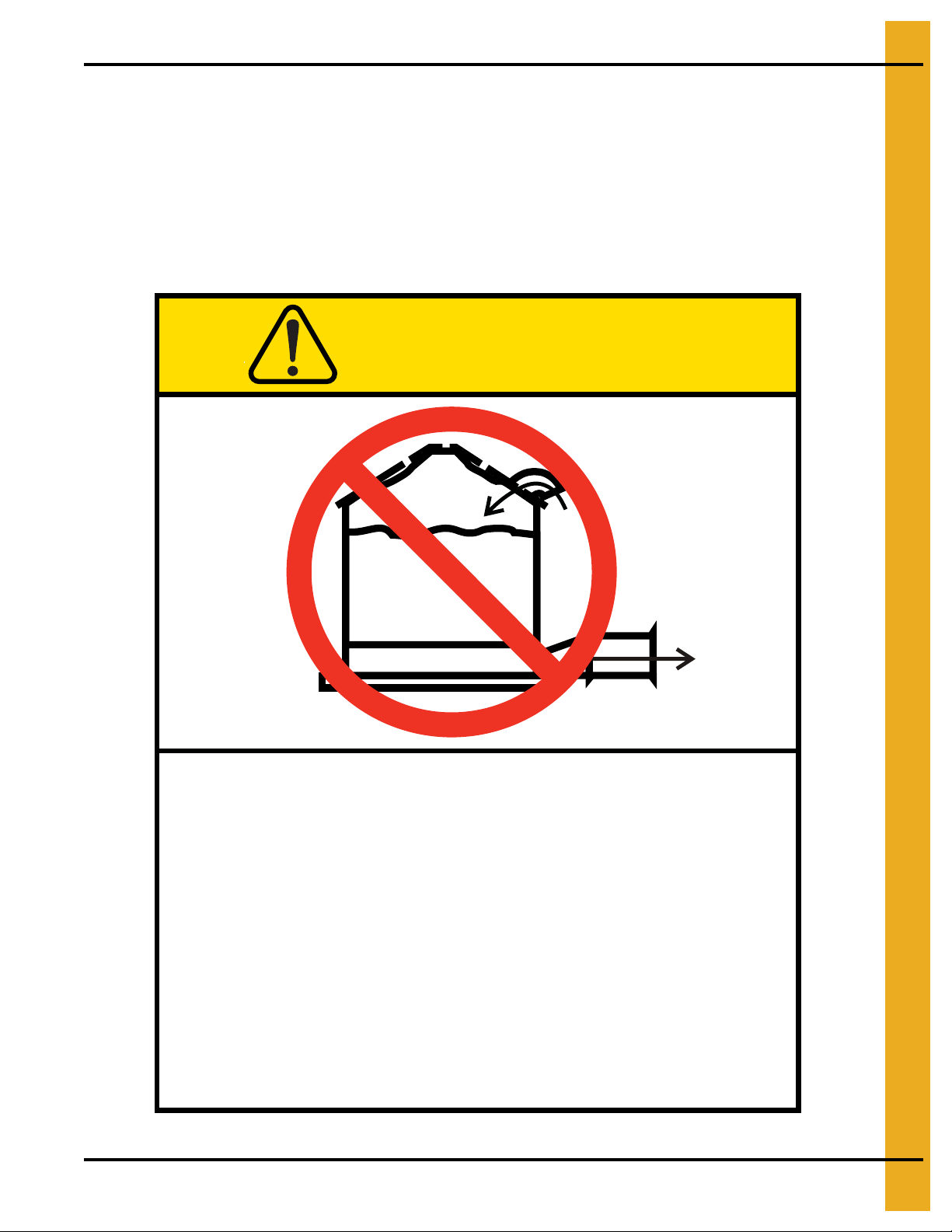
Roof Damage Warning and Disclaimer
Excessive vacuum (or pressure) may
damage roof. Use positive aeration
system. Make sure all roof vents are
open and unobstructed. Start roof
fans when supply fans are started.
Do not operate when conditions exist
that may cause roof vent icing.
DC-969
CAUTION
GSI Group, Inc. 217-226-4421
The manufacturer does not warrant any roof damage caused by excess ive v acuum or internal
pressure from fans or other air moving systems. Adequate ventilation and/or “makeup air”
devices should be provided for all powered air handling systems. The manufacturer does not
recommend the use of downward flow systems (suction). Severe roof damage can result from
any blockage of air passages. Running fans durin g high humidity/cold weather conditions can
cause air exhaust or intake ports to freeze.
2. Decals
PNEG-1894 Top Dry Chute Controller 5
Page 6
2. Decals
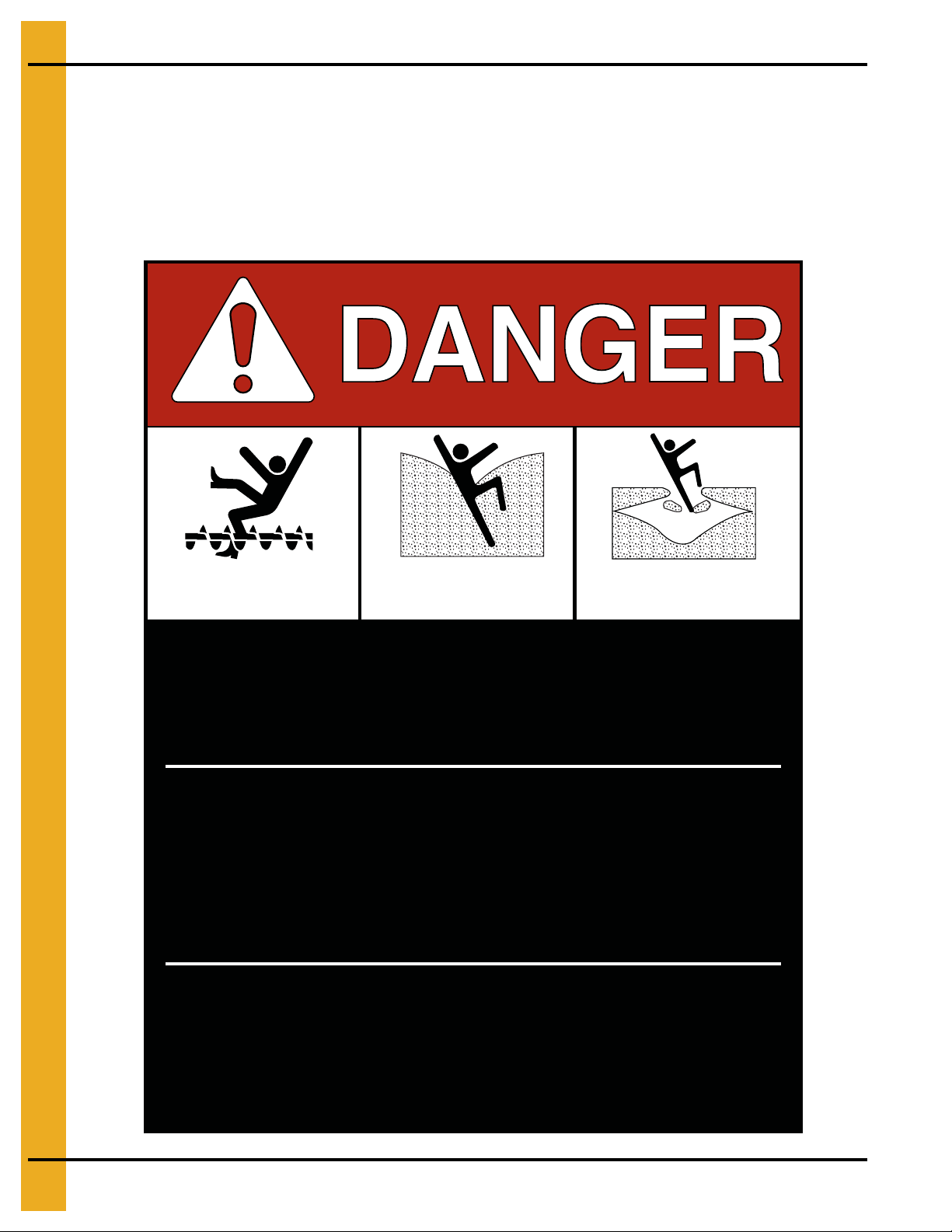
Rotating flighting will
kill or dismember.
Flowing material will
trap and suffocate.
Crusted material will
collapse and suffocate.
Keep clear of all augers.
DO NOT ENTER this bin!
Failure to heed these
warnings will result in
serious injury or death.
If you must enter the bin:
1. Shut off and lock out all power.
2. Use a safety harness and safety line.
3. Station another person outside the bin.
4. Avoid the center of the bin.
5. Wear proper breathing equipment or respirator.
DC-GBC-1A
ATTENTION: The decal shown below should be present on the outside of the door cover of the 2 ring,
24" porthole door cover and the roof manway cover. If a decal has been damaged or is missing in any of
these locations, contact the manufacturer for a free replacement decal.
GSI Decals
1004 E. Illinois St.
Assumption, IL. 62510
Phone: 1-217-226-4421
6 PNEG-1894 Top Dry Chute Controller
Page 7
2. Decals
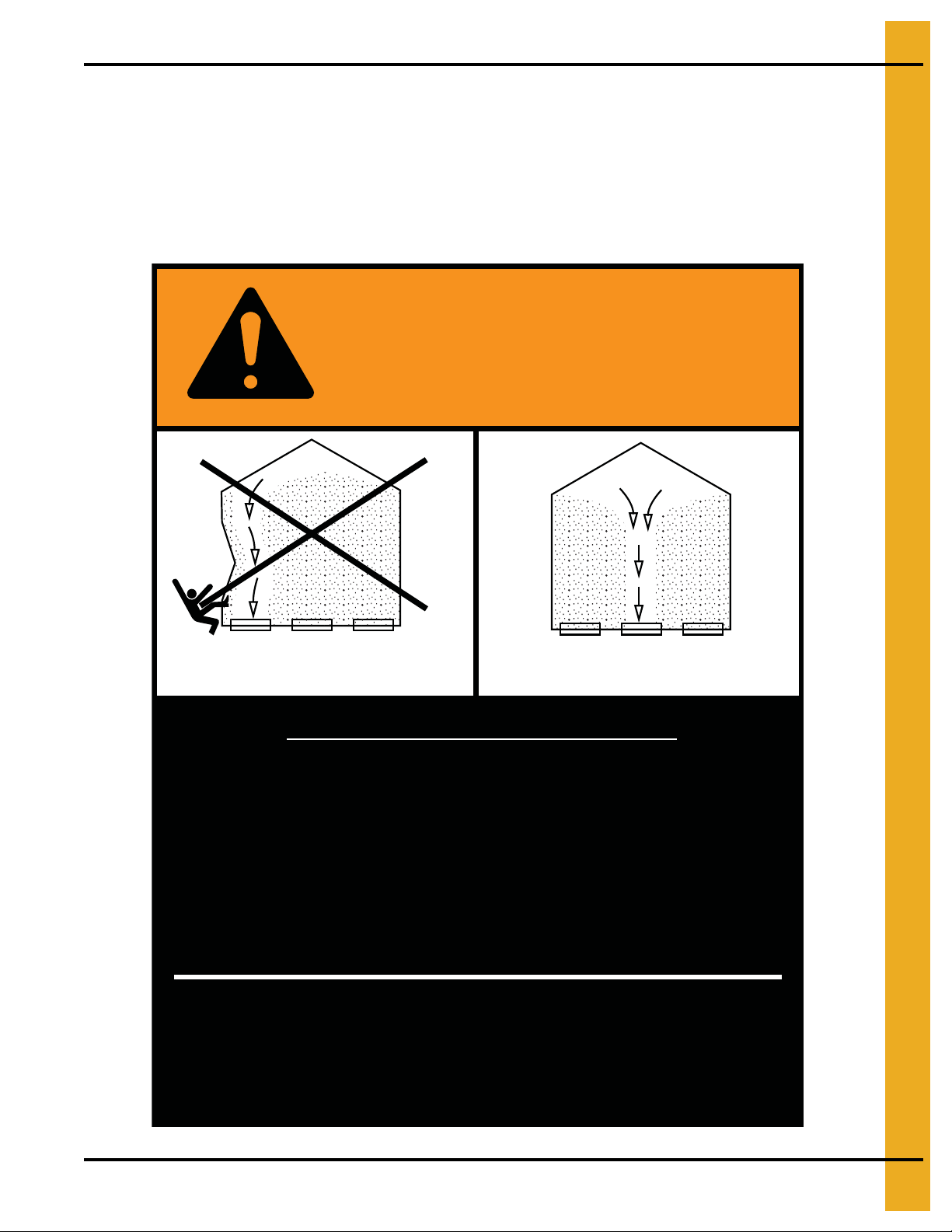
Failure to heed these warnings
could result in serious injury, death,
structural damage or collapse of tank.
1. Use CENTER FLOOR OUTLET ONLY until NO grain
remains above this outlet.
2. Side floor outlets to be used ONLY when above
condition is satisfied.
3. Lock all side floor outlets to avoid accidental
premature use.
4. See manufacturers instructions for proper use of
factory supplied sidedraw (wall) discharge systems.
UNLOADING INSTRUCTIONS:
DC-GBC-2A
WARNING
DON’T
DO
ATTENTION: The decal shown below should be present on the outside of the door cover of the 2 ring,
24" porthole door cover and the roof manway cover. If a decal has been damaged or is missing in any of
these locations, contact the manufacturer for a free replacement decal.
GSI Decals
1004 E. Illinois St.
Assumption, IL. 62510
Phone: 1-217-226-4421
PNEG-1894 Top Dry Chute Controller 7
Page 8

3. Controller Layout
Figure 3A Chute Pulley Cable Location
8 PNEG-1894 Top Dry Chute Controller
Page 9

4. Installation
Chute Controller Installation for Top Dry System
The chute controller is mounted to the side of a Top Dry bin and actuates the chutes that allow the grain
to transfer from the drying floor to the bin floor.
NOTE: Before beginning the chute controller installation, make sure the pulley bracket is properly
installed. The pulley bracket must be position above the chute controller location befor e installing
the stiffener mounting plate.
Locating the Chute Pulley Assembly
1. Position the pulley in the hole that is located 9-3/8" (23.8 cm) horizontally from the center of the
stiffener. NOTE: When positioning the pulley, ensure the pulley cable does not interfere with the
dump chutes. This can only be accomplish at every other stiffener. (See Figure 4A below and
Figure 3A on Page 8.)
Figure 4A
Field drill five (5) 3/8" diameter holes as shown in Figure 4B. Attach the pulley assembly with
5/16" x 3/4" bolts with the neoprene on the inside of the bin. (See Figure 4B.)
Figure 4B
PNEG-1894 Top Dry Chute Controller 9
Page 10

4. Installation
Figure 4C
10 PNEG-1894 Top Dry Chute Controller
Page 11

4. Installation
Attaching the Mounting Plate and Gussets to the Stiffener
1. Position the bottom edge of the stiffener mounting plate 13" from the bottom of the stiffener.
2. Field drill all six (6) holes in the stiffener using the mounting plate as a template for hole locations,
making sure that the holes are drilled on the peaks of corrugation ridge.
3. Attach the stiffener mounting plate (A) using six (6) bolts (B) and nuts (C). (See Figure 4D.)
Figure 4D
Ref # Part # Description
A TD-101327 Stiffener Mounting Plate
B S-7515 Bolt, HHCS 3/8"-16 x 1-1/2" Grade 5
C S-7383 Nylock Nut 3/8"-16 Zinc Grade 5
PNEG-1894 Top Dry Chute Controller 11
Page 12

4. Installation
4. Attach the lower mounting gussets (D) to stiffener mounting plate (A) using three (3) flange bolts (E)
and nuts (F) for each mounting gusset. (See Figure 4E.)
Figure 4E
Ref # Part # Description
A TD-101327 Stiffener Mounting Plate
D TD-101326 Lower Mounting Gussets
E S-6606 Flange Bolt 5/16"-18 x 3/4" ZN Grade 5
F S-3611 Flange Nut 5/16"-18 YDP Grade 2
12 PNEG-1894 Top Dry Chute Controller
Page 13

4. Installation
Assembling the Chain Guard
1. Position the chute controller assembly so that all sides are accessible. Remove the cover from the
chute position controller enclosure.
2. Align the top and bottom tabs of the rear chain guard (B) with holes in the idler sprocket mounting
brackets (C) and attach by inserting flange bolts (D) through the sides and tightening with flange
nuts (E). (See Figure 4F.)
3. Feed chain (A) that is part of the chute position controller drive from the chute position controller
around the small sprocket and out through the back panel and in between the idler sprocket mounting
brackets (C). (See Figure 4F.)
4. Replace cover and secure for lifting. (See Figure 4F.)
Figure 4F
Ref # Part # Description
A TD-101357 #40 Roller Chain
B TD-101336 Rear Chain Guard
C TD-101332 Idler Sprocket Mounting Bracket
D S-6606 Flange Bolt 5/16"-18 x 3/4" ZN Grade 5
E S-361 1 Flange Nut 5/16"-18 YDP Grade 2
PNEG-1894 Top Dry Chute Controller 13
Page 14

4. Installation
Chute position controller enclosure weighs approximately 275 lbs. pounds. Failure
to use proper equipment and personnel when lifting could cause bodily injury or
damage to equipment.
WARNING
Installing the Housing Assembly
1. Lift the housing assembly onto the lower mounting gussets (A), aligning holes in the bottom
of the chute position controller enclosure with the holes in the lower mounting gussets.
2. Remove cover to attach chute position controller enclosure to gussets with six (6) flange bolts (B)
and flange nuts (C). (See Figure 4G.)
3. Field drill all four (4) holes in the bin sidewalls through the four (4) holes in the sidewall mounting
brackets (D), making sure that the holes are drilled on the peaks of the corrugation ridges. Use bolts
to attach housing to bin.
Figure 4G
Ref # Part # Description
A TD-101326 Lower Mounting Gussets
B S-6606 Flange Bolt 5/16"-18 x 3/4" ZN Grade 5
C S-3611 Flange Nut 5/16"-18 YDP Grade 2
D Sidewall Mounting Bracket
14 PNEG-1894 Top Dry Chute Controller
Page 15

4. Installation
Disconnect all power sources before attempting to connect wiring. All wiring
should be done by a certified electrician. Follow all national and local
electrical codes.
WARNING
Testing that the Sprocket Correctly Activates the Limit Switch
1. Field drill two (2) holes in bottom of chute position controller electrical box (A) large enough to
accommodate cables for power and Autoflow controls. Refer to wiring diagrams on Pages 19 an d 20
to feed conduit for wiring to the main power breaker and Autoflow controls. (See Figure 4H.)
2. After wiring and before attaching the chain to the cable, test that the sprocket travels from the open
limit switch position to the close limit switch position. To test sprocket travel:
NOTE: For system to function when testing travel with the cover removed, the damper switch (B)
must be depressed.
a. Use tape to secure damper switch in the depressed position.
b. Ensure the sprocket (C) is in the open position when beginning testing. Use the manual dump
chute switch located on the main control panel to move between the open and closed positions.
Set the sprocket travel to the closed position on the Autoflow control and observe the bolt s in the
sprocket (C) travel from the open (clockwise) position to the closed (counterclockwise) position
to the limit switch (D) as shown in Figure 4H.
Figure 4H
Ref # Part # Description
A TD-101349 Chute Position Controller Electrical Box
B Damper Switch
C TD-101351 S p rocket
D Limit Switch
PNEG-1894 Top Dry Chute Controller 15
Page 16

4. Installation
Connecting the Cable to the Turnbuckle
1. Run the cable from the inside of the bin through the sidewall sheet over the chute pulley on the bin
eave and down to the chain tunbuckle from the controller. (See Figure 4I.)
Figure 4I
Ref # Part # Description
A TD-101335 Front Chain Guard
B TD-101336 Rear Chain Guard
16 PNEG-1894 Top Dry Chute Controller
Page 17

4. Installation
2. Set turnbuckle (D) to the halfway point to allow for adjustment in both directions. (See Figure 4J.)
Figure 4J
Ref # Description
C Chain
D Turnbuckle
E Cable Clamps
3. Bolt the turnbuckle to the chain (C). (See Figure 4J.)
4. Attach the cable to the turnbuckle using cable clamps (E). (See Figure 4J.)
PNEG-1894 Top Dry Chute Controller 17
Page 18

4. Installation
Leveling the Dump Chutes
NOTE: When testing the chute positions, tamper switch must be depressed when the cover is removed
before the system can function. Use tape to secure damper switch in the depressed position.
1. The chain (C) is connected to a cable with a turnbuckle (D). The cable travels up the outside of the bin
to the chute pulley on the bin eave and goes through the sidewall sheet into the bin to the center collar
and down to the chain plate.
(See Figure 4C on Page 10.)
chains. The controller retracts the cable to close the chutes or extends the cable to open the chutes.
2. Dump chutes should be level in the closed position. Use the turnbuckle to adjust the chutes until they
are level.
3. After adjustments are complete, verify the chutes fully open and close. Also, visually verify that the
sprocket goes through a full open to close rotation by performing the limit switch test described
in Step 2 on Page 15.
4. When all adjustments have been made, secure the front chain guard cover to the chute position
controller mount.
5. Install the enclosure cover (A) and secure with flange bolts (B). (See Figure 4K.)
The plate is connected to the chutes via
Figure 4K
Ref # Part # Description
A TD-101330 Enclosure Cover
B S-6606 Flange Bolt 5/16"-18 x 3/4" ZN Grade 5
18 PNEG-1894 Top Dry Chute Controller
Page 19

Actuator Wiring Diagram
5. Wiring and Schematic Diagrams
PNEG-1894 Top Dry Chute Controller 19
Page 20

5. Wiring and Schematic Diagrams
Actuator Wiring Schematic
20 PNEG-1894 Top Dry Chute Controller
Page 21

6. Warranty
9101239_1_CR_rev7.DOC (revised July 2009)
GSI Group, LLC Limited Warranty
The GSI Group, LLC (“GSI”) warrants products which it manufactures to be free of defects in materials and workmanship
under normal usage and conditions for a period of 12 months after sale to the original end-user or if a foreign sale,
14 months from arrival at port of discharge, whichever is earlier. The end-user’s sole remedy (and GSI’s only obligation)
is to repair or replace, at GSI’s option and expense, products that in GSI’s judgment, contain a material defect in materials
or workmanship. Expenses incurred by or on behalf of the end-user without prior written authorization from the GSI
Warranty Group shall be the sole responsibility of the end-user.
Warranty Extensions:
The Limited Warranty period is extended for the following products:
Product Warranty Period
Performer Series Direct Drive Fan Motor 3 Years
AP Fans and Flooring
Cumberland
Feeding/Watering
Systems
Grain Systems Grain Bin Structural Design 5 Years
Grain Systems
Farm Fans
Zimmerman
All Fiberglass Housings Lifetime
All Fiberglass Propellers Lifetime
Feeder System Pan Assemblies 5 Years **
Feed Tubes (1-3/4" and 2.00") 10 Years *
Centerless Augers 10 Years *
Watering Nipples 10 Years *
Portable and Tower Dryers 2 Years
Portable and Tower Dryer Frames and
Internal Infrastructure †
5 Years
* Warranty prorated from list price:
0 to 3 years - no cost to end-user
3 to 5 years - end-user pays 25%
5 to 7 years - end-user pays 50%
7 to 10 years - end-user pays 75%
** Warranty prorated from list price:
0 to 3 years - no cost to end-user
3 to 5 years - end-user pays 50%
† Motors, burner components
and moving parts not included.
Portable dryer screens included.
Tower dryer screens not included.
GSI further warrants that the portable and tower dryer frame and basket, excluding all auger and auger drive components,
shall be free from defects in materials for a period of time beginning on the twelfth (12
and continuing until the sixtieth (60
th
) month from the date of purchase (extended warranty period). During the extended
th
) month from the date of purchase
warranty period, GSI will replace the frame or basket components that prove to be defective under normal conditions
of use without charge, excluding the labor, transportation, and/or shipping costs incurred in the performance of this
extended warranty.
Conditions and Limitations:
THERE ARE NO WARRANTIES THAT EXTEND BEYOND THE LIMITED WARRANTY DESCRIPTION SET FORTH
ABOVE. SPECIFICALLY, GSI MAKES NO FURTHER WARRANTY OF ANY KIND, EXPRESS OR IMPLIED,
INCLUDING, WITHOUT LIMITATION, WARRANTIES OF MERCHANTABILITY OR FITNESS FOR A PARTICULAR
PURPOSE OR USE IN CONNECTION WITH: (I) PRODUCT MANUFACTURED OR SOLD BY GSI OR (II) ANY ADVICE,
INSTRUCTION, RECOMMENDATION OR SUGGESTION PROVIDED BY AN AGENT, REPRESENTA TIVE OR
EMPLOYEE OF GSI REGARDING OR RELATED TO THE CONFIGURATION, INSTALLATION, LAYOUT, SUITABILITY
FOR A PARTICULAR PURPOSE, OR DESIGN OF SUCH PRODUCTS.
GSI shall not be liable for any direct, indirect, incidental or consequential damages, including, without limitation, loss of
anticipated profits or benefits. The sole and exclusive remedy is set forth in the Limited Warranty, which shall not exceed
the amount paid for the product purchased. This warranty is not transferable and applies only to the original end-user. GSI
shall have no obligation or responsibility for any representations or warranties made by or on behalf of any dealer, agent
or distributor.
GSI assumes no responsibility for claims resulting from construction defects or unauthorized modifications to products
which it manufactured. Modifications to products not specifically delineated in the manual accompanying the equipment at
initial sale will void the Limited Warranty.
This Limited Warranty shall not extend to products or parts which have been damaged by negligent use, misuse, alteration,
accident or which have been improperly/inadequately maintained. This Limited Warranty extends solely to products
manufactured by GSI.
Prior to installation, the end-user has the responsibility to comply with federal, state and local codes which apply to the
location and installation of products manufactured or sold by GSI.
PNEG-1894 Top Dry Chute Controller 21
Page 22

This equipment shall be installed in accordance with
the current installation codes and applicable
regulations, which should be carefully followed in all
cases. Authorities having jurisdiction should be
consulted before installations are made.
Copyright © 2012 by GSI Group
Printed in the USA
GSI Group
1004 E. Illinois St.
Assumption, IL 62510-0020
Phone: 1-217-226-4421
Fax: 1-217-226-4420
www.gsiag.com
CN-302164
 Loading...