

Page 1
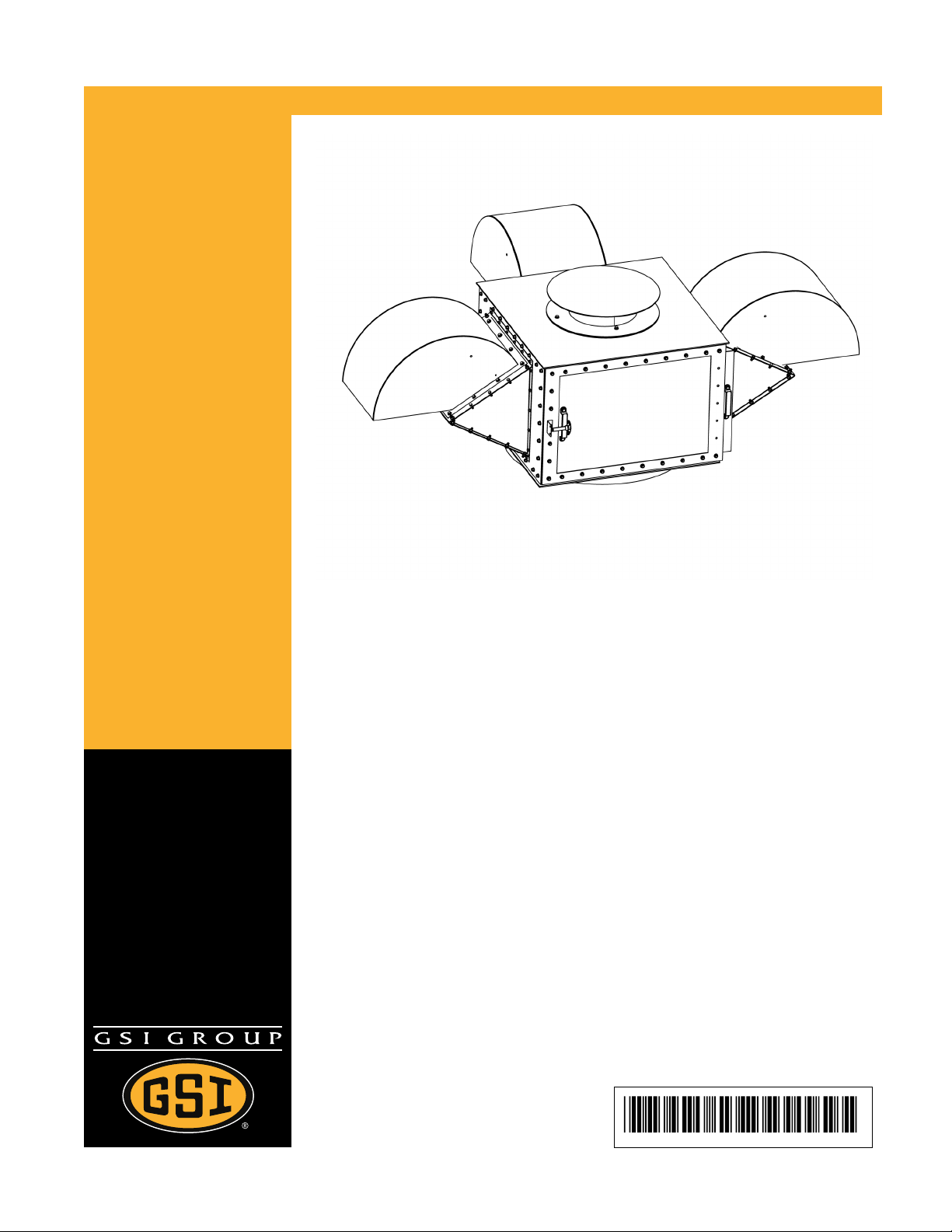
Top Dry Air Box
Assembly Manual
PNEG-1890
Date: 07-10-12
PNEG-1890
Page 2

All information, illustrations, photos, and specifications in this manual are based on the latest
information available at the time of publication. The right is reserved to make changes at any
time without notice.
2 Pneg-1890 Top Dry Air Box
Page 3

Table of Contents
Contents
Chapter 1 Top Dry Air Box Assembly.........................................................................................................5
Assemble Air Box Covers.............................................................................................................6
Assemble Vent to Angle Plate.......................................................................................................7
Attach Vent Assembly to Side Plate ..............................................................................................8
Attach Side Plate Assembly to Support Frame ...............................................................................9
Assemble Top Spout to Support Frame ....................................................................................... 10
Install Inner Spout...................................................................................................................... 11
Assemble Door Frame ............................................................................................................... 12
Install Sliding Access Door .........................................................................................................13
GSI Group, LLC Limited Warranty............................................................................................ 15
Pneg-1890 Top Dry Air Box 3
Page 4

NOTES
4 Pneg-1890 Top Dry Air Box
Page 5

1 Top Dry Air Box Assembly
Topics Covered in this Chapter
▪ Assemble Air Box Covers
▪ Assemble Vent to Angle Plate
▪ Attach Vent Assembly to Side Plate
▪ Attach Side Plate Assembly to Support Frame
▪ Assemble Top Spout to Support Frame
▪ Install Inner Spout
▪ Assemble Door Frame
▪ Install Sliding Access Door
Use a silicone based caulk along all connecting surfaces throughout the assembly to
NOTICE
assure a water tight fit.
Pneg-1890 Top Dry Air Box
5
Page 6

Chapter 1 Top Dry Air Box Assembly
Assemble Air Box Covers
The air box covers consist of the air box right and left covers and the air box cover angle plate. This assembly will be the base for the vent assembly.
1. Apply caulk (F) along the bolt holes in both the right side panel (B) and the left side panel (C).
2. Install the right side panel (B) and the left side panel (C) to the angle plate (A) using bolts (D) and
nuts (E).
Callout Part Number Description
A TD-101154 Air Box Cover — Angle Plate
B TD-101152 Air Box Cover — Right
C TD-101151 Air Box Cover — Left
D S-275 5/16”-18 X 3/4” Grade 5 Hex Bolt
E S-396 5/16”-18 Zinc YDP Grade 2 Hex Nut
F CH-6873 Silicone caulk area indicated by gray dashed line.
6 Pneg-1890 Top Dry Air Box
Page 7

Chapter 1 Top Dry Air Box Assembly
Assemble Vent to Angle Plate
Assembling the vents to the angle plates before attaching the angle plates to the side plates will allow
easier access to hardware during installation.
1. Apply caulk around angle plate opening next to bolt holes (C).
2. Align holes in vent flange (A) with holes in angle plate (B).
3. Attach vent to angle plate using bolt (D) and nut (E).
Callout Part Number Description
A MIS-6773 Slim Roof Vent Housing
B TD-101154 Air Box Cover — Angle Plate
C MIS-6778 Base Gasket indicated by gray dashed line.
D S-275 5/16”-18 X 3/4” Grade 5 Hex Bolt
E S-396 5/16”-18 Zinc YDP Grade 2 Hex Nut
Pneg-1890 Top Dry Air Box
7
Page 8

Chapter 1 Top Dry Air Box Assembly
Attach Vent Assembly to Side Plate
Attaching the vent assemblies to the side plates first will allow for easier access to hardware during
installation.
1. Apply caulk (C) along the perimeter of the bolt holes in the side plate (B).
2. Align holes in vent assembly (A) with those in the side plate (B).
3. Fasten vent assembly (A) to side plate (B) using screws (D) and nuts (E).
Callout Part Number Description
A NA Vent Assembly
B TD-101153 Air Box Cover Side Plate
C CH-6873 Silicone caulk area indicated by gray dashed line.
D S-275 5/16”-18 X 3/4” Grade 5 Hex Bolt
E S-396 5/16”-18 Zinc YDP Grade 2 Hex Nut
8 Pneg-1890 Top Dry Air Box
Page 9

Chapter 1 Top Dry Air Box Assembly
Attach Side Plate Assembly to Support Frame
The side plate assemblies will cover three sides of the air box support frame. The remaining side will
house the access door.
1. Apply caulk (C) along the perimeter of the bolt holes on the support frame (B).
2. Align holes in side plate assembly (A) with those on the support frame (B).
3. Fasten side plate assembly (A) to support Frame (B) using screws (D).
Callout Part Number Description
A NA Side Plate Assembly
B TD-101155 Air Box Support Frame
C CH-6873 Silicone caulk area indicated by gray dashed line.
D S-7221 5/16”-18 X 3/4” Grade 2 Self Tapping Screw
Pneg-1890 Top Dry Air Box 9
Page 10

Chapter 1 Top Dry Air Box Assembly
Assemble Top Spout to Support Frame
The top spout is fastened to the top of the air box using three bolts through threaded plates located on the
inside of the box.
1. Align holes in bottom of top spout (A) with holes in rubber gasket (C) and support frame top (D).
2. Fasten together using only three bolts (B). Do not install the bolt located on the door side.
Callout Part Number Description
A TD-101313 Air Box Top Spout Weldment
B S-277 5/16”-18 X 1–1/4” Grade 5 Bin Bolt
C TD-101325 Rubber Gasket Seal
D TD-101155 Air Box Support Frame
10 Pneg-1890 Top Dry Air Box
Page 11

Chapter 1 Top Dry Air Box Assembly
Install Inner Spout
The inner spout slides onto the support plates located inside the air box under the top spout and is fastened in place with a keeper bolt.
1. Slide flanges of inner spout (A) onto spout support plates (D).
2. Fasten in place with keeper bolt (C).
Callout Part Number Description
A TD-101310 Air Box Inner Spout Weldment
B TD-101155 Air Box Cover Support Frame
C S-277 5/16”-18 X 1–1/4” YDP Grade 5 Bin Bolt
D NA Spout Support Plate
E TD-101313 Air Box Top Spout Weldment
Pneg-1890 Top Dry Air Box 11
Page 12

Chapter 1 Top Dry Air Box Assembly
Assemble Door Frame
The air box sliding door frame is made of three plates. One side of the middle plate is removed to allow the
door to slide between the two outer plates.
1. Apply caulk along the perimeter of the bolt holes in the support frame (D).
2. Align holes in outer and inner door plates (A and C) with holes in support frame.
3. Attach together using bolts (B).
Callout Part Number Description
A TD-101318 Air Box Sliding Door Outer Plate
B S-7221 5/16” x 3/4” Grade 2 Self Tapping Screw
C TD-101319 Air Box Sliding Door Inner Plate
D CH-6873 Silicone caulk area indicated by gray dashed line.
12 Pneg-1890 Top Dry Air Box
Page 13

Chapter 1 Top Dry Air Box Assembly
Install Sliding Access Door
The top dry air box sliding door allows access to the inside of the air box to easily remove the inner tube.
1. Slide access door (A) into opening on side of door frame.
2. Attach handles (B) to door using bolts (C) and nuts (D).
3. Install latch bracket (E) to air box side panel next to handle.
4. Install the latch (F) to the latch bracket (E).
Callout Part Number Description
A TD-101320 Air Box Sliding Door
B PR-331 Handle
C S-275 5/16”-18 X 3/4” YDP Grade 5 Bin Bolt
D S-396 5/16”-18 YDP Grade 2 Hex Nut
E TD-101321 Air Box Sliding Door Latch Bracket
F CRP-4654 Latch
Pneg-1890 Top Dry Air Box 13
Page 14

NOTES
14 Pneg-1890 Top Dry Air Box
Page 15

GSI Group, LLC Limited Warranty
GSI Group, LLC Limited Warranty
The GSI Group, LLC (“GSI”) warrants products which it manufactures to be free of defects in materials and workmanship
under normal usage and conditions for a period of 12 months after sale to the original end-user or if a foreign sale, 14
months from arrival at port of discharge, whichever is earlier. The end-user’s sole remedy (and GSI’s only obligation) is to
repair or replace, at GSI’s option and expense, products that in GSI’s judgment, contain a material defect in materials or
workmanship. Expenses incurred by or on behalf of the end-user without prior written authorization from the GSI Warranty
Group shall be the sole responsibility of the end-user.
Warranty Extensions:
The Limited Warranty period is extended for the following products:
Product Warranty Period
Performer Series Direct Drive Fan Motor 3 Years
AP Fans and Flooring
Cumberland
Feeding/Watering
Systems
Grain Systems Grain Bin Structural Design
Grain Systems
Farm Fans
Zimmerman
All Fiberglass Housings
All Fiberglass Propellers
Feeder System Pan Assemblies
Feed Tubes (1-3/4" and 2.00")
Centerless Augers
Watering Nipples
Portable and Tower Dryers
Portable and Tower Dryer Frames and Internal Infrastructure †
Lifetime
Lifetime
5 Years **
10 Years *
10 Years *
10 Years *
5 Years
2 Years
5 Years
* Warranty prorated from list price:
0 to 3 years - no cost to end-user
3 to 5 years - end-user pays 25%
5 to 7 years - end-user pays 50%
7 to 10 years - end-user pays 75%
** Warranty prorated from list price:
0 to 3 years - no cost to end-user
3 to 5 years - end-user pays 50%
† Motors, burner components and
moving parts not included.
Portable dryer screens included.
Tower dryer screens not included.
GSI further warrants that the portable and tower dryer frame and basket, excluding all auger and auger drive components,
shall be free from defects in materials for a period of time beginning on the twelfth (12
and continuing until the sixtieth (60
th
) month from the date of purchase (extended warranty period). During the extended
th
) month from the date of purchase
warranty period, GSI will replace the frame or basket components that prove to be defective under normal conditions of use
without charge, excluding the labor, transportation, and/or shipping costs incurred in the performance of this extended
warranty.
Conditions and Limitations:
THERE ARE NO WARRANTIES THAT EXTEND BEYOND THE LIMITED WARRANTY DESCRIPTION SET FORTH
ABOVE. SPECIFICALLY, GSI MAKES NO FURTHER WARRANTY OF ANY KIND, EXPRESS OR IMPLIED, INCLUDING,
WITHOUT LIMITATION, WARRANTIES OF MERCHANTABILITY OR FITNESS FOR A PARTICULAR PURPOSE OR
USE IN CONNECTION WITH: (I) PRODUCT MANUFACTURED OR SOLD BY GSI OR (II) ANY ADVICE, INSTRUCTION,
RECOMMENDATION OR SUGGESTION PROVIDED BY AN AGENT, REPRESENTATIVE OR EMPLOYEE OF GSI
REGARDING OR RELATED TO THE CONFIGURATION, INSTALLATION, LAYOUT, SUITABILITY FOR A PARTICULAR
PURPOSE, OR DESIGN OF SUCH PRODUCTS.
GSI shall not be liable for any direct, indirect, incidental or consequential damages, including, without limitation, loss of
anticipated profits or benefits. The sole and exclusive remedy is set forth in the Limited Warranty, which shall not exceed
the amount paid for the product purchased. This warranty is not transferable and applies only to the original end-user. GSI
shall have no obligation or responsibility for any representations or warranties made by or on behalf of any dealer, agent or
distributor.
GSI assumes no responsibility for claims resulting from construction defects or unauthorized modifications to products
which it manufactured. Modifications to products not specifically delineated in the manual accompanying the equipment at
initial sale will void the Limited Warranty.
This Limited Warranty shall not extend to products or parts which have been damaged by negligent use, misuse, alteration,
accident or which have been improperly/inadequately maintained. This Limited Warranty extends solely to products manufactured by GSI.
Prior to installation, the end-user has the responsibility to comply with federal, state and local codes which apply to the location and installation of products manufactured or sold by GSI.
9101239_1_CR_rev7.DOC (revised July 2009)
Pneg-1890 Top Dry Air Box 15
Page 16

This equipment shall be installed in accordance with the
current installation codes and applicable regulations
which should be carefully followed in all cases.
Authorities having jurisdiction should be consulted
before installations are made.
Copyright © 2012 by GSI Group
Printed in the USA
GSI Group
1004 E. Illinois St..
Assumption, IL 62510-0020
Phone: 1-217-226-4421
Fax: 1-217-226-4420
www.gsiag.com
CN #207183
 Loading...