

Page 1
PNEG-1880
105' Externally Stiffened 2 Ring
Door for 2
and 3rd Ring
Installation Manual
PNEG-1880
Date: 05-21-12
nd
Page 2

2 PNEG-1880 105' Externally Stiffened 2 Ring Door for 2nd and 3rd Ring
Page 3

Table of Contents
Contents
Chapter 1 Introduction ..........................................................................................................................................4
Chapter 2 Safety .....................................................................................................................................................5
Safety Guidelines .................................................................................................................................. 5
General Safety Statement ..................................................................................................................... 6
Safety Instructions ..................... ... .... .......................................... ... ... ..................................................... 7
Safety Sign-Off Sheet ........................................................................................................................... 9
Proper Storage of Grain Bin/Silo Materials Prior to Construction ....................................................... 10
Chapter 3 Safety Decals ......................................................................................................................................11
Roof Damage Warning and Disclaimer ............................................................................................... 11
Chapter 4 Important Note ....................................................................................................................................14
Chapter 5 Assembly Instructions ......................... .................................................... ..........................................15
Chapter 6 Assembly Drawings ...........................................................................................................................17
Chapter 7 Warranty ..............................................................................................................................................29
PNEG-1880 105' Externally Stiffened 2 Ring Door for 2nd and 3rd Ring 3
Page 4

1. Introduction
READ THIS MANUAL carefully to learn how to properly use and install equipment. Failure to do so could
result in personal injury or equipment damage.
INSPECT the shipment immediately upon arrival. The customer is responsible for ensuring that all
quantities are correct. The customer should report and note any damage or shortage on the bill of lading
to justify their claim to the transport company.
THIS MANUAL SHOULD BE CONSIDERED a permanent part of your equipment and should be easily
accessible when needed.
This warranty provides you the assurance that the company will back its products when defects appear
within the warranty period. In some circumstances, the company also provides field improvements, often
without charge to the customer, even if the product is out of warranty. Should the equipment be abused,
or modified to change its performance beyond the factory specifications, the warranty will become void
and field improvements may be denied.
4 PNEG-1880 105' Externally Stiffened 2 Ring Door for 2nd and 3rd Ring
Page 5
2. Safety
DANGER
WARNING
CAUTION
NOTICE
This is the safety alert symbol. It is used to alert you
to potential personal injury hazards. Obey all safety
messages that follow this symbol to avoid possible
injury or death.
WARNING indicates a hazardous situation which, if not
avoided, could result in death or serious injury.
CAUTION, used with the safety alert symbol, indicates a
hazardous situation which, if not avoided, could result in
minor or moderate injury.
NOTICE is used to address practices not related to
personal injury.
DANGER indicates a hazardous situation which, if not
avoided, will result in death or serious injury.
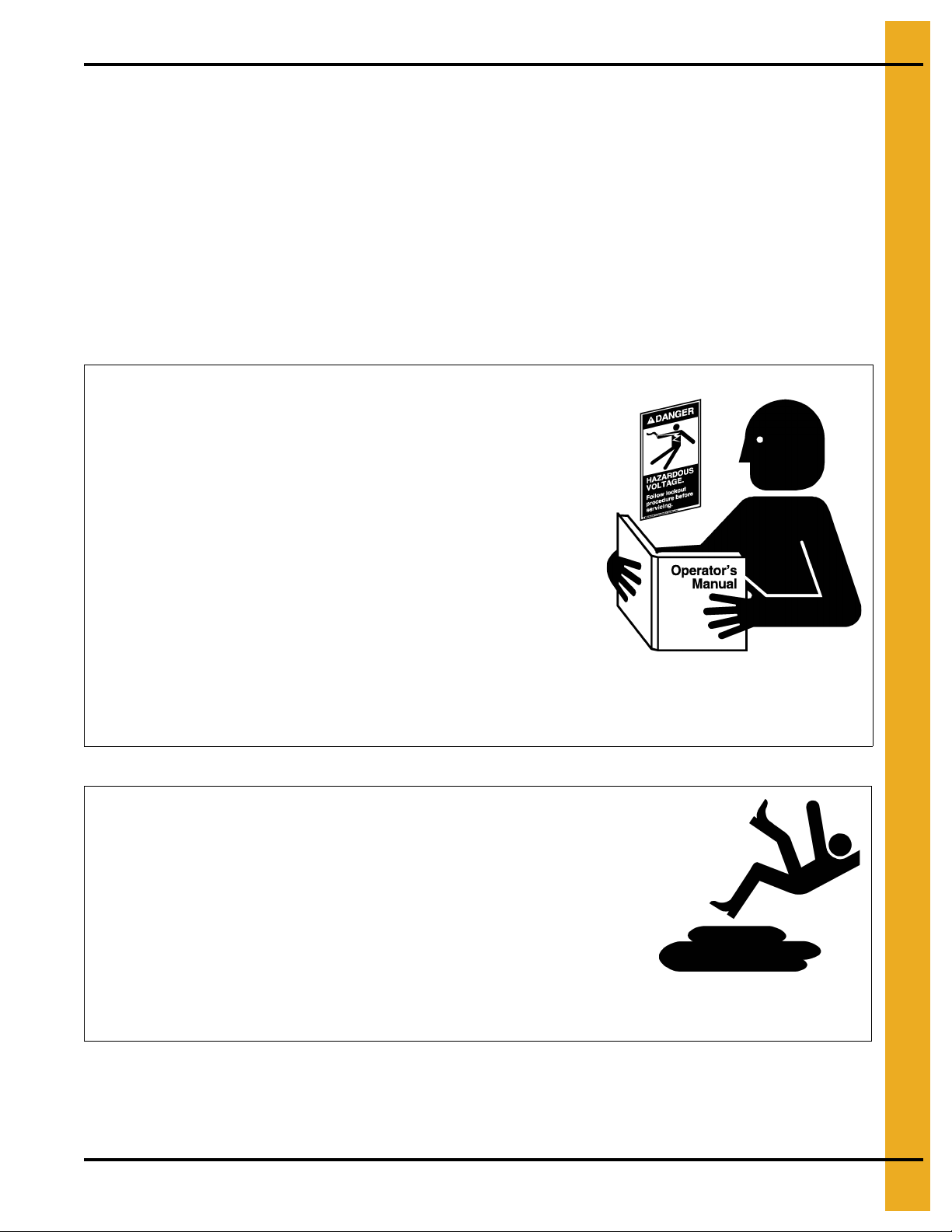
Safety Guidelines
This manual contains information that is important for you, the owner/operator, to know and understand.
This information relates to protecting personal safety and preventing equipment problems. It is the
responsibility of the owner/operator to inform anyone operating or working in the area of this equipment
of these safety guidelines. To help you recognize this information, we use the symbols that are defined
below. Please read the manual and pay attention to these sections. Failure to read this manual and its
safety instructions is a misuse of the equipment and may lead to serious injury or death.
PNEG-1880 105' Externally Stiffened 2 Ring Door for 2nd and 3rd Ring 5
Page 6
2. Safety
This product has sharp edges, which may cause serious injury. To avoid injury, handle
sharp edges with caution and always use proper protective clothing and equipment.
General Safety Statement
Our foremost concern is your safety and the safety of others associated with grain handling equipment.
This manual is to help you understand safe operating procedures and some problems that may be
encountered by the operator and other personnel.
As owner and/or operator, you are responsible to know what requirements, hazards and precautions exist
and inform all personnel associated with the equipment or in the area. Safety precautions may be required
from the personnel. Avoid any alterations to the equipment, which may produce a very dangerous
situation, where SERIOUS INJURY or DEATH may occur.
You should consider the location of the bin site relative to power line locations or electrical transmission
equipment. Contact your local power company to review your installation plan or for information
concerning required equipment clearance. Clearance of portable equipment that may be taken to the bin
site should also be reviewed and considered. Any electrical control equipment in contact with the bin
should be properly grounded and installed in accordance with National Electric Code provisions and other
local or national codes.
This product is intended for the use of grain storage only. Any other use is a misuse of the product.
Sidewall bundles or sheets must be stored in a safe manner. The safest method of storing sidewall
bundles is laying horizontally with the arch of the sheet upward, like a dome. Sidewall sheets stored on
edge must be secured so that they cannot fall over and cause injury. Use care when handling and moving
sidewall bundles.
Personnel operating or working around equipment should read this manual. This manual must be
delivered with equipment to its owner. Failure to read this manual and its safety instructions is a misuse
of the equipment.
6 PNEG-1880 105' Externally Stiffened 2 Ring Door for 2nd and 3rd Ring
Page 7
2. Safety
Follow Safety Instructions
Carefully read all safety messages in this manual and
safety signs on your machine. Keep signs in good
condition. Replace missing or damaged safety signs. Be
sure new equipment components and repair parts include
the current safety signs. Replacement safety signs are
available from the manufacturer.
Learn how to operate the machine and how to use controls
properly. Do not let anyone operate without instruction.
Keep your machinery in proper working condition.
Unauthorized modifications to the machine may impair
the function and/or safety and affect machine life.
If you do not understand any part of this manual or need
assistance, contact your dealer.
Read and Understand Manual
Practice Safe Maintenance
Understand service procedures before doing work. Keep area
clean and dry.
Never lubricate, service, or adjust machine while it is in operation.
Keep hands, feet, and clothing away from rotating parts.
Keep all parts in good condition and properly installed. Fix
damage immediately . Replace worn or broken p arts. Remove any
built-up grease, oil, and debris.
Maintain Equipment
and Work Area
Safety Instructions
Our foremost concern is your safety and the safety of others associated with this equipment. We want to
keep you as a customer. This manual is to help you understand safe operating procedures and some
problems that may be encountered by the operator and other personnel.
As owner and/or operator, it is your responsibility to know what requirements, hazards, and precautions
exist, and to inform all personnel associated with the equipment or in the area. Safety precautions may be
required from the personnel. Avoid any alterations to the equipment. Such alterations may produce a very
dangerous situation where SERIOUS INJURY or DEATH may occur.
This equipment shall be installed in accordance with the current installation codes and applicable
regulations, which should be carefully followed in all cases. Authorities having jurisdiction should be
consulted before installations are made.
PNEG-1880 105' Externally Stiffened 2 Ring Door for 2nd and 3rd Ring 7
Page 8
2. Safety
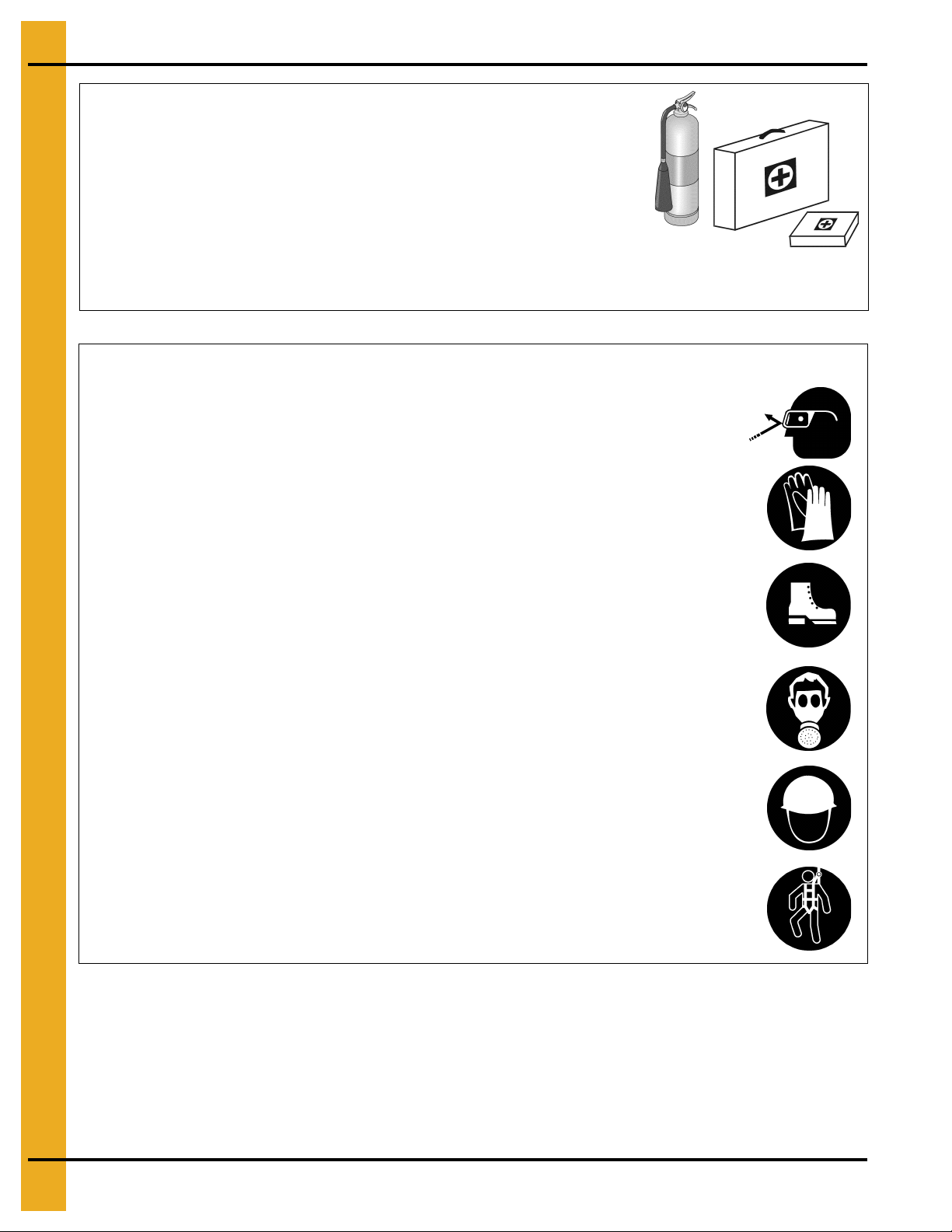
Prepare for Emergencies
Be prepared if fire starts.
Keep a first aid kit and fire extinguisher handy.
Keep emergency numbers for doctors, ambulance service,
hospital, and fire department near your telephone.
Keep Emergency Equipment
Quickly Accessible
Wear Protective Clothing
Wear close-fitting clothing and safety equipment appropriate
to the job.
Remove all jewelry.
Tie long hair up and back.
Wear safety glasses at all times to protect eyes from debris.
Wear gloves to protect your hands from sharp edges on
plastic or steel parts.
Wear steel-toed boots to help protect your feet from falling
debris. Tuck in any loose or dangling shoestrings.
A respirator may be needed to prevent breathing potentially
toxic fumes and dust.
Wear a hard hat to help protect your head.
Wear appropriate fall protection equipment when working at
elevations greater than six feet (6').
Eye Protection
Gloves
Steel-Toed Boots
Respirator
Hard Hat
Fall Protection
8 PNEG-1880 105' Externally Stiffened 2 Ring Door for 2nd and 3rd Ring
Page 9

2. Safety
Safety Sign-Off Sheet
As a requirement of O.S.H.A., it is necessary for the employer to train the employee in the safe operating
and safety procedures for this equipment. This sign-off sheet is provided for your convenience and
personal record keeping. All unqualified persons are to stay out of the work area at all times. It is strongly
recommended that another qualified person who knows the shut down procedure be in the area in the
event of an emergency.
Date Employee Name Supervisor Name
PNEG-1880 105' Externally Stiffened 2 Ring Door for 2nd and 3rd Ring 9
Page 10

2. Safety
Proper Storage of Grain Bin/Silo Materials Prior to Construction
Wet storage stain (rust) will develop when closely packed bundles of galvanized material, such as sidewall
and roof sheets, have moisture present. Inspect roof and sidewall bundles on arrival for any moisture. If
moisture is present, it must not be allowed to remain between the she ets. Separate the sheets or panels
immediately and wipe them down. Spray with a light oil or diesel fuel.
If possible, sidewall bundles, roof sheets and other closely packed galvanized materials should be stored
in a dry, climate controlled building. If outdoor storage is unavoidable, the materials should be stored so
that they are raised above the ground and vegetation. Any stacking an d spacing mat erials sho uld not be
corrosive or wet. Be sure to protect materials from the weather, but permit air movement around the
bundles if possible.
Storing roof bundles and sidewall sheets at a slight incline can also help minimize the presence of
moisture. Storing the bundles with the center of the dome up (like an arch) is one option for minimizing
moisture during storage. Sidewall bundles can also be stored on edge but must be secured so that they
do not fall over and cause injury.
If “white rust” or “wet storage stain” occurs, contact the manufacturer imme diately about ways to minimize
the adverse effect upon the galvanized coating.
10 PNEG-1880 105' Externally Stiffened 2 Ring Door for 2nd and 3rd Ring
Page 11

3. Safety Decals
Excessive vacuum (or pressure) may
damage roof. Use positive aeration
system. Make sure all roof vents are
open and unobstructed. Start roof
fans when supply fans are started.
Do not operate when conditions exist
that may cause roof vent icing.
DC-969
CAUTION!
The manufacturer does not warrant any roof damage caused by excess ive v acuum or internal
pressure from fans or other air moving systems. Adequate ventilation and/or “makeup air”
devices should be provided for all powered air handling systems. The manufacturer does not
recommend the use of downward flow systems (suction). Severe roof damage can result from
any blockage of air passages. Running fans durin g high humidity/cold weather conditions can
cause air exhaust or intake ports to freeze.
Roof Damage Warning and Disclaimer
PNEG-1880 105' Externally Stiffened 2 Ring Door for 2nd and 3rd Ring 11
Page 12

3. Safety Decals
ATTENTION: The decal shown below should be present on the outside of the door cover of the 2 ring,
24" porthole door cover and the roof manway cover. If a decal has been damaged or is missing in any of
these locations, contact the manufacturer for a free replacement decal.
GSI Decals
1004 E. Illinois St.
Assumption, IL. 62510
Phone: 1-217-226-4421
Rotating flighting will
kill or dismember.
Flowing material will
trap and suffocate.
Crusted material will
collapse and suffocate.
Keep clear of all augers.
DO NOT ENTER this bin!
If you must enter the bin:
1. Shut off and lock out all power.
2. Use a safety harness and safety line.
3. Station another person outside the bin.
4. Avoid the center of the bin.
5. Wear proper breathing equipment or respirator.
Failure to heed these
warnings will result in
serious injury or death.
DC-GBC-1A
12 PNEG-1880 105' Externally Stiffened 2 Ring Door for 2nd and 3rd Ring
Page 13

3. Safety Decals
Failure to heed these warnings
could result in serious injury, death,
structural damage or collapse of tank.
1. Use CENTER FLOOR OUTLET ONLY until NO grain
remains above this outlet.
2. Side floor outlets to be used ONLY when above
condition is satisfied.
3. Lock all side floor outlets to avoid accidental
premature use.
4. See manufacturers instructions for proper use of
factory supplied sidedraw (wall) discharge systems.
UNLOADING INSTRUCTIONS:
DC-GBC-2A
WARNING
DON’T
DO
ATTENTION: The decal shown below should be present on the outside of the door cover of the 2 ring,
24" porthole door cover and the roof manway cover. If a decal has been damaged or is missing in any of
these locations, contact the manufacturer for a free replacement decal.
GSI Decals
1004 E. Illinois St.
Assumption, IL. 62510
Phone: 1-217-226-4421
PNEG-1880 105' Externally Stiffened 2 Ring Door for 2nd and 3rd Ring 13
Page 14

4. Important Note
This GSI Commercial 2 Ring Door is designed for use in the 2.66" corrugation NCL series of tanks
manufactured after 1991 utilizing the “universal” or hat shaped stiffener. This door is intended for use with
a tank specifically structured for the installation of the 2 ring door. Special sidewall sheets are provided
as part the tank sidewall bundles. You must consult with GSI concerning retrofitting into any existing
GSI manufactured tank.
The door package NCWT0297 is designed for use in 105' (32.00 m) diameter ta nks with a maximum eave
height = 90'-10"/27.69 meters and external stiffeners.
You should not attempt to install this door in any 2.66" corrugation GSI “Z” stiffener tank (pre 1991 series).
This door should not be installed in any GSI 4.00" corrugation series tank.
Consult with GSI concerning retrofitting into any existing GSI manufactured tank to determine compatibility
of the door package with the existing sidewall and stiffener configuration.
This door should not be installed in any tank not manufactured by GSI.
14 PNEG-1880 105' Externally Stiffened 2 Ring Door for 2nd and 3rd Ring
Page 15

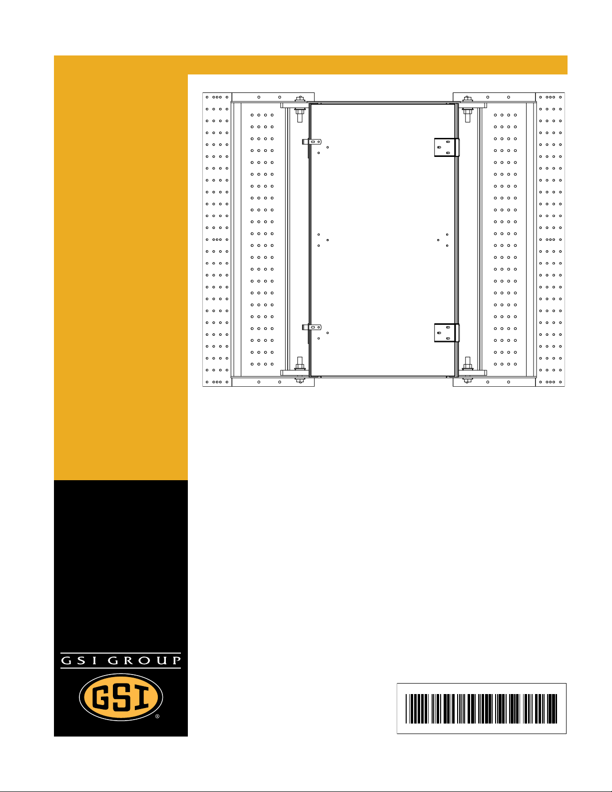
5. Assembly Instructions
Written instructions for installation of a NCWT0435 (105' diame ter bin/silo) 2 ring door package in
nd
the 2
and 3rd rings of an externally stiffened tank.
nd
1. The commercial 2 ring door is installed in the 2
and 3rd rings from the bottom.
2. The door should normally be placed in line with the conveyor. An intermediate discharge well should
be located near the wall to clear grain from the area of the access door (as with any access door).
3. The door has an inside frame weldment and an external frame weldment/assembly. If the tank has
not been erected the internal frame weldment should be placed inside the tank before erection. If the
tank has been erected or erection has begun, it will be necessary to remove sidewall and stiffeners
in the door placement area to place the inside frame weldment.
The external door frame stiffener support will mount at the standard externally stiffened tank ancho r
bolt location. (See Page 27.) If bolts have been pre-placed then place the stiffener support over the
pre-placed bolts. If drill in anchors are to be used it is recommended the holes be pre-drilled at the
proper location. Attach the stiffener support to the bottom ring of sidewall and place the external
frame with stiffeners on top of the stiffener supports.
4. The stiffeners are mounted in the frame directly under the tank stiffener columns. (See Pages 17
and 26.) For the case of the externally stiffened tank these stiffeners will be mounted in the exte rnal
frame. The frame should have the stiffeners already in place with two (2) bolts to hold them in
location. These bolts will need to be removed to install the door, however the stiffeners may be left
in position in the frame. The stiffeners will mount in the frame such that the tank stiffener will bear
directly above it. Should the stiffeners not be so placed, they should be placed in that location.
Special base stiffener weldments mount above the frame stiffeners. The door stiffeners should also
bear directly onto the support stiffeners below the external frame.
5. Jamb plates (NCWT0417) are provided for attachment of the sidewall sheets to the door frame.
The jamb plate will mount between the internal and external frame. Place the jamb plate between the
internal and external frame and bolt the frame, plate and stiffener together utilizing 7/16" diameter
bolts. Utilize 7/16" x 2-1/2" bolts (See Page 18) for the plate to jamb connection; utilize 7/16" x 3" bolt
for stiffener to jamb to plate connection. At the jamb plate to frame connection install the bolts with
the head and sealing washer on the outside of the tank. At the stiffener to frame to plate connection
install the bolts with the head and sealing washer on the inside of the tank.
The internal door panel hinges will mount utilizing stiffener to frame bolts (on the inside of the tank).
Place an additional sealing washer under the hinge at those bolt locations before bolting it in place.
Place as shown on the attached diagrams. The external door cover hinges will mount inside the
stiffener on the outside of the tank.
6. The sidewall sheets to the left and right of the door will mount to the outside of the jamb plate.
Two (2) special short sidewall sheets (44") and two (2) standard length (119"), special punched
sheets are provided. Attach the sidewall to the jamb plate utilizing 3/8" diameter x 2" long bolts.
(See Page 18.) Corrugated sealing strip, CWT-0053 is provided. This may be mounted at the o uter
edge and inner edge of the jamb plate to sidewall interf ace. Caulk around the seal strip as well. A flat
washer may be required under the nut for certain gauge thicknesses. Bolt head/sealing washer
should be on the outside of the tank for this connection.
NOTE: For tanks that utilize 13 gauge or thinner material 3/8" x 1" bolts may be used to attach the
sidewall to the jamb plate.
PNEG-1880 105' Externally Stiffened 2 Ring Door for 2nd and 3rd Ring 15
Page 16

5. Assembly Instructions
Written instructions for installation of a NCWT0435 (105' diameter bin/silo) 2 ring door package in
nd
the 2
and 3rd rings of an externally stiffened tank. (Continued)
The horizontal seam of the sidewall sheet above and below the door frame will bolt to the jamb plate
where it extends above and below the door frame. The sidewall will be on the exterior of the plate.
Install top/bottom seal angle (NCWT0239) at the area the plate does not extend above and below
the door. Bolt the seal angle to the sidewall horizontal seam and utilize silicon caulk as needed to
seal this location.
The exterior door frame will mount directly above the stiffener supports. Special base stiffeners will
mount directly above the frame stiffener. Shim as necessary for firm support and bolt the stiffeners
together using a 1" x 4-1/2" bolt, 1" nut and 1" washer.
7. Bearing pins, WD-6224 eight (8), are mounted to the inside frame flange at the eight (8)
large/0.65" x 0.750" slots. Use 5/16" x 1-1/2" bin bolts (S-2741) and attach the pin to these
eight (8) locations by inserting the grooved pin into the hole and running the 5/16" bolt to th e inside.
(See Page 21.) Use 5/16" flat washer (S-845) and 5/16" flanged head nut (S-3611) to secure
bearing pin.
8. Assemble the door handle reinforcement angles, door handles, latches and hinges to the top and
bottom inner door panels as shown in the assembly sketches. (See Pages 19 and 20.) Install the
1/2" x 1-1/2" bolts in the outer door frame at four (4) locations and thread the door latch bar holder
(WD-6234) onto the bolt. The door handle will mount over these holders then installed. Utilize
washers if necessary to adjust the latch bar holder position. (See Page 21.) Mount the door panel
onto the four (4) bearing pins and lock the latches over the latch bar holder. Then attach the door
panel hinges to the frame hinges. Adjust hinges and latch bar holders until door panels swing freely
and the latch bars lock over the holder completely. Apply 1" x 1/2" foam seal strip to inner frame
weldment to seal inner door panels.
9. Attach the outer cover angles (NCWT0174) to the outer frame weldment with 5/16" x 1-1/4" bin bolts
(S-277). Remove the sealing washer from the bolt and replace it with a flat washer. Use a f lat washer
on all slotted connections. Bolt heads should be on the outside for these connections. (See Page 24.)
10. Attach the outer cover hinge weldments (NCWT0165) and latch plates (NCWT0166) to the outer
cover angles as shown on Page 24. Use 5/16" x 1-1/4" bolts with flat washers on each side for all
connections. Bolt heads should be on the inside for all connections.
11. Assemble the exterior cover as shown in the assembly sketch. (See Page 25.) Install the retaining
brackets (WD-033), outer cover hinges (NCWT0170) and reinforcement channels (NCWT0162) to
the outer cover as shown. Use 5/16" x 1-1/4" bolts for all hinge and latch bracket connections and
5/16" x 3/4" bolts for all reinforcement channel connections. (See Page 25.) Bolt head with sealing
washer should be on the outside for all of these connections. An additional s ealing washer should be
placed between the retaining bracket/outer cover hinge and exterior cover. Adjust the outer cover
hinges as necessary until door opens and closes smoothly. Apply sealant all around door frame at
outer cover location. Check to ensure that the unloading decals (DC-GBC-2A and DC-GBC-2S)
are installed on the outside of the outer door cover. Check to ensure that the danger decals
(DC-GBC-1A and DC-GBC-1S) are installed on the inside of the outer door cover. If decals are
missing or damaged contact GSI immediately.
12. Caulk as necessary at the top and bottom juncture of the door frame and the sidewall and foundation.
16 PNEG-1880 105' Externally Stiffened 2 Ring Door for 2nd and 3rd Ring
Page 17

6. Assembly Drawings
Figure 6A
PNEG-1880 105' Externally Stiffened 2 Ring Door for 2nd and 3rd Ring 17
Page 18

6. Assembly Drawings
NOTE: Reference the gauge sheet attached to manual for actual sheet
usages/gauges on the particular tank being erected.
Refer to assembly instructions Steps 5 and 6 on Page 15 for assembly
and bolt usage.
Figure 6B
18 PNEG-1880 105' Externally Stiffened 2 Ring Door for 2nd and 3rd Ring
Page 19

6. Assembly Drawings
Figure 6C
PNEG-1880 105' Externally Stiffened 2 Ring Door for 2nd and 3rd Ring 19
Page 20

6. Assembly Drawings
Figure 6D
20 PNEG-1880 105' Externally Stiffened 2 Ring Door for 2nd and 3rd Ring
Page 21

6. Assembly Drawings
WD-6224 Four (4) per door assembly attach
bearing pins loosely in door frame. Install door
panels in proper position, then center bearing pins
in door panel holes and tighten. Refer to assembly
instructions Step 7 on Page 16.
WD-6234 Four (4) per door panel
refer to assembly instructions Step 8
on Page 16 for order of assembly.
Figure 6E
PNEG-1880 105' Externally Stiffened 2 Ring Door for 2nd and 3rd Ring 21
Page 22

6. Assembly Drawings
Figure 6F
22 PNEG-1880 105' Externally Stiffened 2 Ring Door for 2nd and 3rd Ring
Page 23

6. Assembly Drawings
Figure 6G
PNEG-1880 105' Externally Stiffened 2 Ring Door for 2nd and 3rd Ring 23
Page 24

6. Assembly Drawings
Figure 6H
24 PNEG-1880 105' Externally Stiffened 2 Ring Door for 2nd and 3rd Ring
Page 25

6. Assembly Drawings
Figure 6I
PNEG-1880 105' Externally Stiffened 2 Ring Door for 2nd and 3rd Ring 25
Page 26

6. Assembly Drawings
Ref # Description
1 Standard Sidewall Sheet
2 Stiffener Support
3 Standard Sidewall Sheet
4 Special Long Sidewall Sheet
5 Special Short Sidewall Sheet
6 Outer Frame Weldment
7 Door Stiffener Weldment
8 Special Base Stiffener Weldment
9 Standard Stiffener Line
Figure 6J
26 PNEG-1880 105' Externally Stiffened 2 Ring Door for 2nd and 3rd Ring
Page 27

6. Assembly Drawings
Figure 6K
PNEG-1880 105' Externally Stiffened 2 Ring Door for 2nd and 3rd Ring 27
Page 28

NOTES
28 PNEG-1880 105' Externally Stiffened 2 Ring Door for 2nd and 3rd Ring
Page 29

7. Warranty
9101239_1_CR_rev7.DOC (revised July 2009)
GSI Group, LLC Limited Warranty
The GSI Group, LLC (“GSI”) warrants products which it manufactures to be free of defects in materials and workmanship
under normal usage and conditions for a period of 12 months after sale to the original end-user or if a foreign sale,
14 months from arrival at port of discharge, whichever is earlier. The end-user’s sole remedy (and GSI’s only obligation)
is to repair or replace, at GSI’s option and expense, products that in GSI’s judgment, contain a material defect in materials
or workmanship. Expenses incurred by or on behalf of the end-user without prior written authorization from the GSI
Warranty Group shall be the sole responsibility of the end-user.
Warranty Extensions:
The Limited Warranty period is extended for the following products:
Product Warranty Period
Performer Series Direct Drive Fan Motor 3 Years
AP Fans and Flooring
Cumberland
Feeding/Watering
Systems
Grain Systems Grain Bin Structural Design 5 Years
Grain Systems
Farm Fans
Zimmerman
All Fiberglass Housings Lifetime
All Fiberglass Propellers Lifetime
Feeder System Pan Assemblies 5 Years **
Feed Tubes (1-3/4" and 2.00") 10 Years *
Centerless Augers 10 Years *
Watering Nipples 10 Years *
Portable and Tower Dryers 2 Years
Portable and Tower Dryer Frames and
Internal Infrastructure †
5 Years
* Warranty prorated from list price:
0 to 3 years - no cost to end-user
3 to 5 years - end-user pays 25%
5 to 7 years - end-user pays 50%
7 to 10 years - end-user pays 75%
** Warranty prorated from list price:
0 to 3 years - no cost to end-user
3 to 5 years - end-user pays 50%
† Motors, burner components
and moving parts not included.
Portable dryer screens included.
Tower dryer screens not included.
GSI further warrants that the portable and tower dryer frame and basket, excluding all auger and auger drive components,
shall be free from defects in materials for a period of time beginning on the twelfth (12
and continuing until the sixtieth (60
th
) month from the date of purchase (extended warranty period). During the extended
th
) month from the date of purchase
warranty period, GSI will replace the frame or basket components that prove to be defective under normal conditions
of use without charge, excluding the labor, transportation, and/or shipping costs incurred in the performance of this
extended warranty.
Conditions and Limitations:
THERE ARE NO WARRANTIES THAT EXTEND BEYOND THE LIMITED WARRANTY DESCRIPTION SET FORTH
ABOVE. SPECIFICALLY, GSI MAKES NO FURTHER WARRANTY OF ANY KIND, EXPRESS OR IMPLIED,
INCLUDING, WITHOUT LIMITATION, WARRANTIES OF MERCHANTABILITY OR FITNESS FOR A PARTICULAR
PURPOSE OR USE IN CONNECTION WITH: (I) PRODUCT MANUFACTURED OR SOLD BY GSI OR (II) ANY ADVICE,
INSTRUCTION, RECOMMENDATION OR SUGGESTION PROVIDED BY AN AGENT, REPRESENTA TIVE OR
EMPLOYEE OF GSI REGARDING OR RELATED TO THE CONFIGURATION, INSTALLATION, LAYOUT, SUITABILITY
FOR A PARTICULAR PURPOSE, OR DESIGN OF SUCH PRODUCTS.
GSI shall not be liable for any direct, indirect, incidental or consequential damages, including, without limitation, loss of
anticipated profits or benefits. The sole and exclusive remedy is set forth in the Limited Warranty, which shall not exceed
the amount paid for the product purchased. This warranty is not transferable and applies only to the original end-user. GSI
shall have no obligation or responsibility for any representations or warranties made by or on behalf of any dealer, agent
or distributor.
GSI assumes no responsibility for claims resulting from construction defects or unauthorized modifications to products
which it manufactured. Modifications to products not specifically delineated in the manual accompanying the equipment at
initial sale will void the Limited Warranty.
This Limited Warranty shall not extend to products or parts which have been damaged by negligent use, misuse, alteration,
accident or which have been improperly/inadequately maintained. This Limited Warranty extends solely to products
manufactured by GSI.
Prior to installation, the end-user has the responsibility to comply with federal, state and local codes which apply to the
location and installation of products manufactured or sold by GSI.
PNEG-1880 105' Externally Stiffened 2 Ring Door for 2nd and 3rd Ring 29
Page 30

This equipment shall be installed in accordance with
the current installation codes and applicable
regulations, which should be carefully followed in all
cases. Authorities having jurisdiction should be
consulted before installations are made.
Copyright © 2012 by GSI Group
Printed in the USA
GSI Group
1004 E. Illinois St.
Assumption, IL 62510-0020
Phone: 1-217-226-4421
Fax: 1-217-226-4420
www.gsiag.com
CN-209114
 Loading...