

Page 1
Top Dry Ladders, Safety Cage,
and Platforms
Assembly Manual
PNEG-1877
Date: 04-04-12
PNEG-1877
Page 2

All information, illustrations, photos, and specifications in this manual are based on the latest
information available at the time of publication. The right is reserved to make changes at any
time without notice.
2 Pneg-1877 Top Dry Ladders, Safety Cage, and Platforms
Page 3

Contents
Chapter 1 Top Dry Ladder and Platform Layouts...........................................................................................5
Available Top Dry Ladder and Platform Packages .............................................................................5
5 Ring Top Dry Platform and Ladder Packages .................................................................................6
7 Ring Top Dry Platform and Ladder Packages .................................................................................7
8 Ring Top Dry Platform and Ladder Packages .................................................................................8
9 Ring Top Dry Platform and Ladder Packages .................................................................................9
10 Ring Top Dry Platform and Ladder Packages..............................................................................10
11 Ring Top Dry Platform and Ladder Packages.............................................................................. 11
12 Ring Top Dry Platform and Ladder Packages..............................................................................12
Chapter 2 Ladders ......................................................................................................................................13
Ladder Extension Rail Installation ..................................................................................................13
Ladder Section Assembly..............................................................................................................14
Ladder Standoff Bracket Detail ...................................................................................................... 15
Chapter 3 Eave Platform ............................................................................................................................. 17
Eave Platform Mounting Angle Location .........................................................................................17
Eave Starter Bracket and Ladder Assembly ....................................................................................19
Eave Platform Assembly ...............................................................................................................20
Adjustable Eave Braces ................................................................................................................21
Top Dry Eave Platform Parts.......................................................................................................... 22
Chapter 4 Storage Chamber Platform ......................................................................................................... 25
Storage Chamber Platform Assembly.............................................................................................25
Storage Chamber Platform Parts ...................................................................................................26
Extension Angle Hole Detail ..........................................................................................................28
Chapter 5 Safety Cage Assembly................................................................................................................29
Adapter Assembly Detail ...............................................................................................................29
Connection Detail ......................................................................................................................... 29
Intermediate Safety Cage Hoop Assembly......................................................................................30
Safety Cage Hoop Bracket Detail ...................................................................................................31
Safety Cage Vertical Supports .......................................................................................................32
Safety Cage Sections ...................................................................................................................32
48” Safety Cage Bell Section ......................................................................................................... 33
Pneg-1877 Top Dry Ladders, Safety Cage, and Platforms 3
Page 4

NOTES
4 Pneg-1877 Top Dry Ladders, Safety Cage, and Platforms
Page 5
1 Top Dry Ladder and Platform
Layouts
Topics Covered in this Chapter
▪ Available Top Dry Ladder and Platform Packages
▪ 5 Ring Top Dry Platform and Ladder Packages
▪ 7 Ring Top Dry Platform and Ladder Packages
▪ 8 Ring Top Dry Platform and Ladder Packages
▪ 9 Ring Top Dry Platform and Ladder Packages
▪ 10 Ring Top Dry Platform and Ladder Packages
▪ 11 Ring Top Dry Platform and Ladder Packages
▪ 12 Ring Top Dry Platform and Ladder Packages
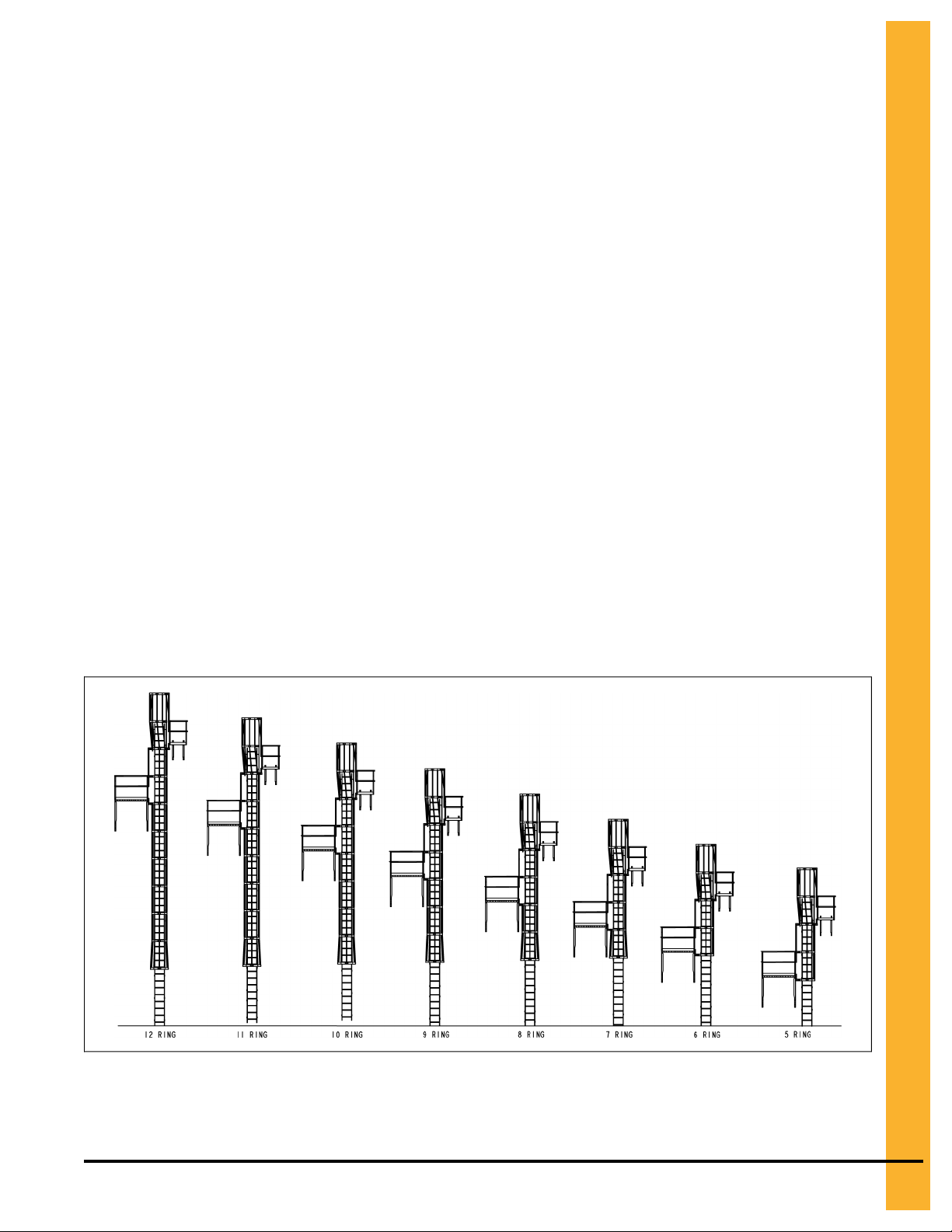
Available Top Dry Ladder and Platform Packages
Ladder and Platform packages are available for Top Dry systems ranging in size from 5 Rings to 12 Rings.
Packages include ladders, eave platform, storage chamber platform and safety cages.
NOTE: Platforms may be installed on either left or right side of ladder as long as platforms are on opposite
sides of the ladder.
Figure 1-1 Available Ladder and Platform Packages
Pneg-1877 Top Dry Ladders, Safety Cage, and Platforms
5
Page 6
Chapter 1 Top Dry Ladder and Platform Layouts
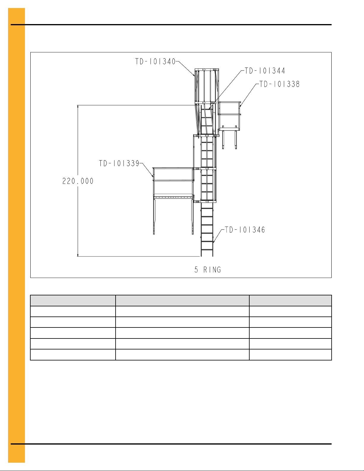
5 Ring Top Dry Platform and Ladder Packages
Figure 1-2 5 Ring Top Dry Package Locations
Table 1-1 5 Ring Top Dry Packages
Callout Description Quantity
TD-101338 Top Dry Eave Platform 1
TD-101339 Top Dry STORAGE CHAMBER PLATFORM 1
TD-101340 Top Dry Platform Cage Package 1
TD-101344 Top Dry Ladder Package (12') 1
TD-101346 8' Ladder Package 1
6 Pneg-1877 Top Dry Ladders, Safety Cage, and Platforms
Page 7
Chapter 1 Top Dry Ladder and Platform Layouts
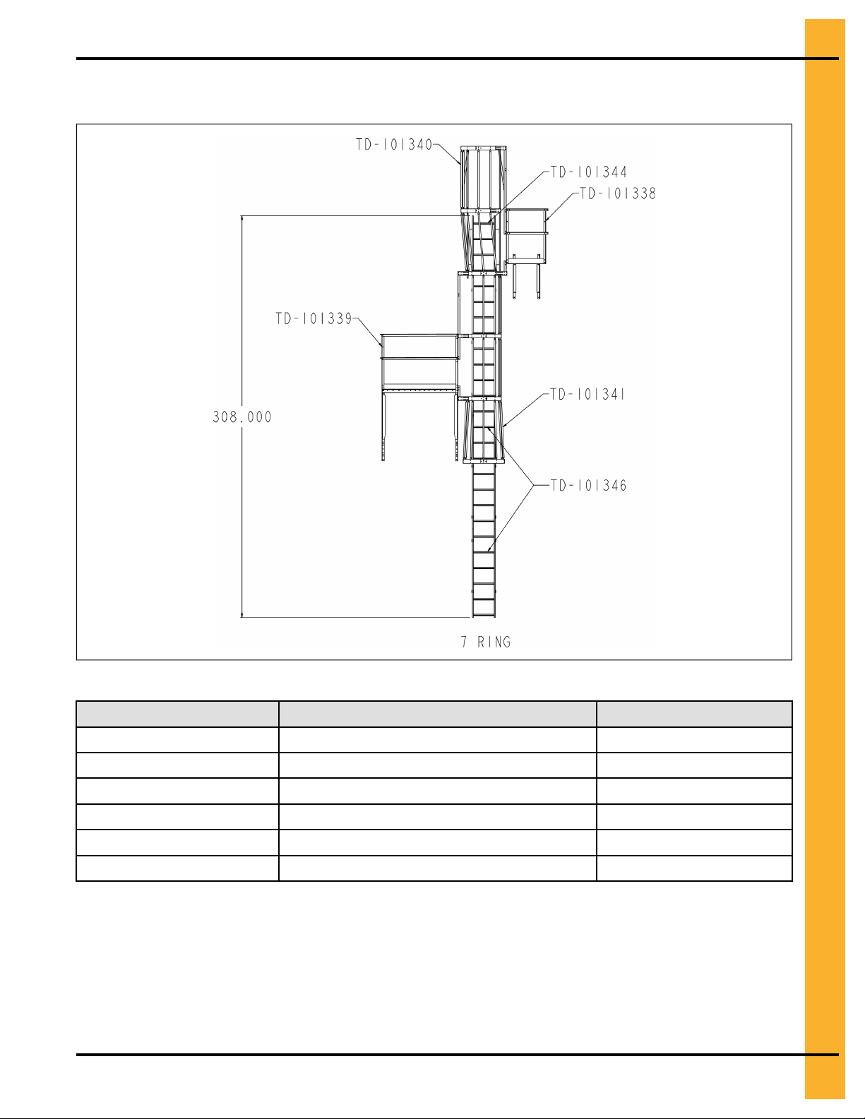
7 Ring Top Dry Platform and Ladder Packages
Figure 1-3 7 Ring Top Dry Package Locations
Table 1-2 7 Ring Top Dry Packages
Callout Description Quantity
TD-101338 Top Dry Eave Platform 1
TD-101339 Top Dry STORAGE CHAMBER PLATFORM 1
TD-101340 Top Dry Platform Cage Package 1
TD-101344 Top Dry Ladder Package (12') 1
TD-101345 4' Standard Ladder Package 1
TD-101346 8' Ladder Package 1
Pneg-1877 Top Dry Ladders, Safety Cage, and Platforms
7
Page 8
Chapter 1 Top Dry Ladder and Platform Layouts
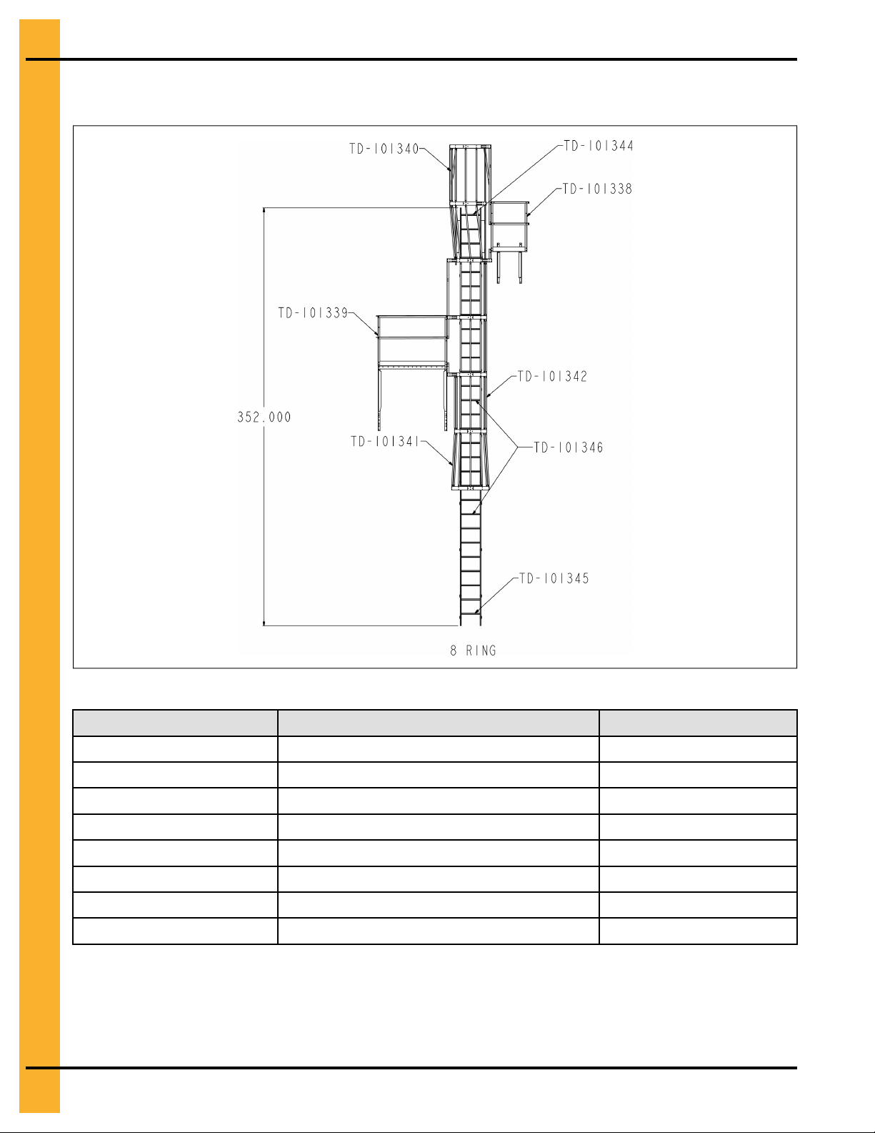
8 Ring Top Dry Platform and Ladder Packages
Figure 1-4 8 Ring Top Dry Package Locations
Table 1-3 8 Ring Top Dry Packages
Callout Description Quantity
TD-101338 Top Dry Eave Platform 1
TD-101339 Top Dry STORAGE CHAMBER PLATFORM 1
TD-101340 Top Dry Platform Cage Package 1
TD-101341 4’ Bell Package 1
TD-101342 4’ Safety Cage 1
TD-101344 Top Dry Ladder Package (12') 1
TD-101345 4’ Standard Ladder Package 1
TD-101346 8' Ladder Package 2
8 Pneg-1877 Top Dry Ladders, Safety Cage, and Platforms
Page 9
Chapter 1 Top Dry Ladder and Platform Layouts
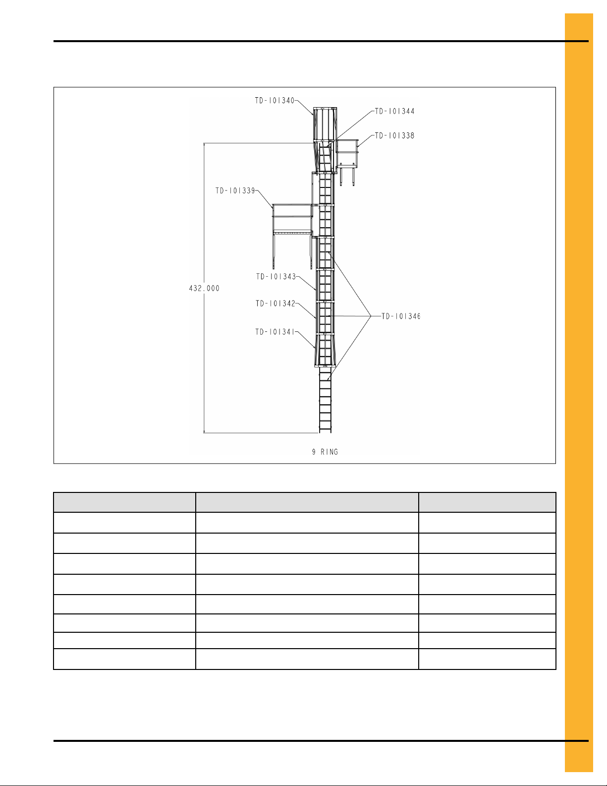
9 Ring Top Dry Platform and Ladder Packages
Figure 1-5 9 Ring Top Dry Package Locations
Table 1-4 9 Ring Top Dry Packages
Callout
TD-101338
TD-101339 Top Dry STORAGE CHAMBER PLATFORM 1
TD-101340 Top Dry Platform Cage Package 1
TD-101341 4’ Bell Package 1
TD-101342 4’ Safety Cage 1
TD-101343 8’ Standard Safety Cage 1
TD-101344 Top Dry Ladder Package (12') 1
TD-101346 8' Ladder Package
Pneg-1877 Top Dry Ladders, Safety Cage, and Platforms 9
Description
Top Dry Eave Platform
Quantity
1
3
Page 10
Chapter 1 Top Dry Ladder and Platform Layouts
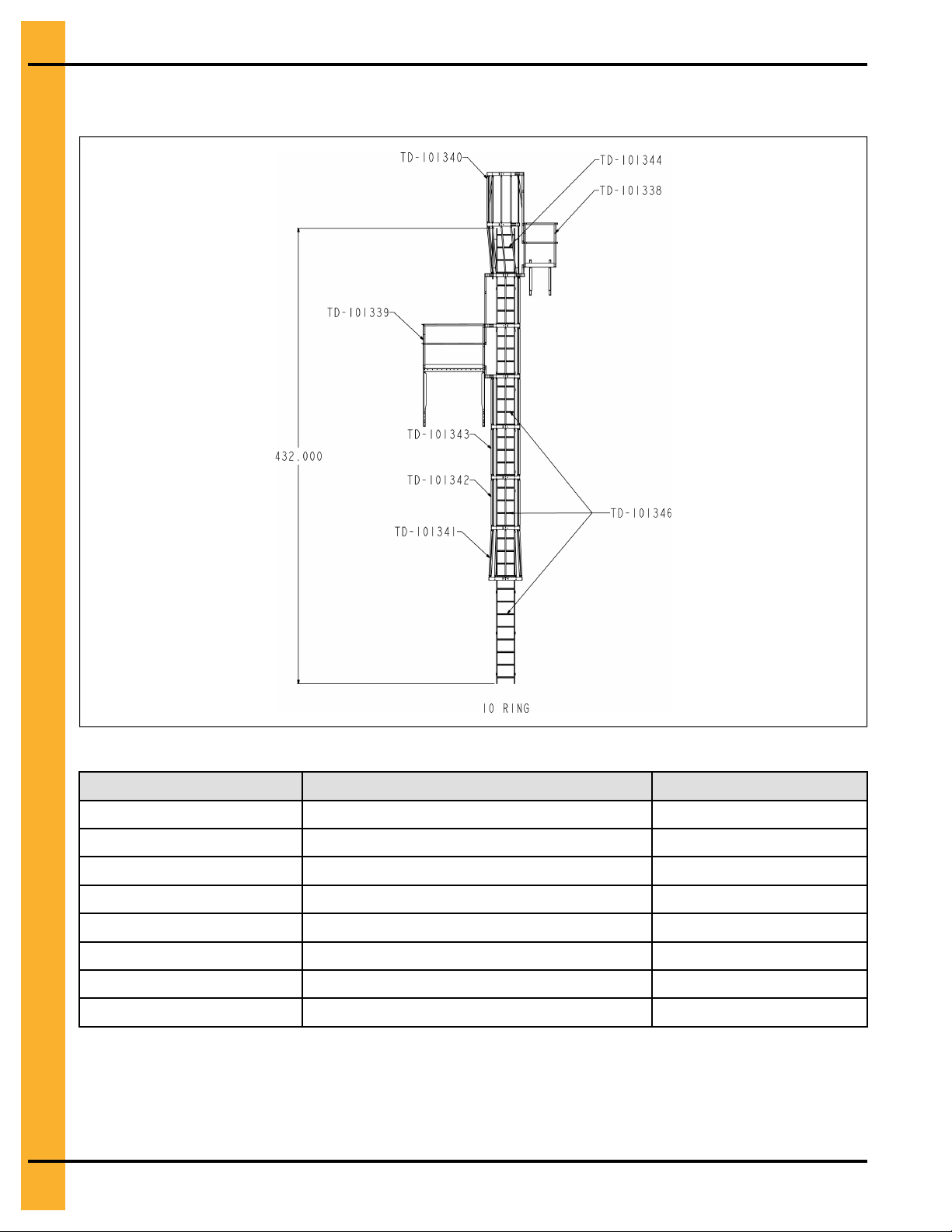
10 Ring Top Dry Platform and Ladder Packages
Figure 1-6 10 Ring Top Dry Package Locations
Table 1-5 10 Ring Top Dry Packages
Callout Description Quantity
TD-101338 Top Dry Eave Platform 1
TD-101339 Top Dry STORAGE CHAMBER PLATFORM 1
TD-101340 Top Dry Platform Cage Package 1
TD-101341 4’ Bell Package 1
TD-101342 4’ Safety Cage 1
TD-101343 8’ Standard Safety Cage 1
TD-101344 Top Dry Ladder Package (12') 1
TD-101346 8' Ladder Package 3
10 Pneg-1877 Top Dry Ladders, Safety Cage, and Platforms
Page 11
Chapter 1 Top Dry Ladder and Platform Layouts
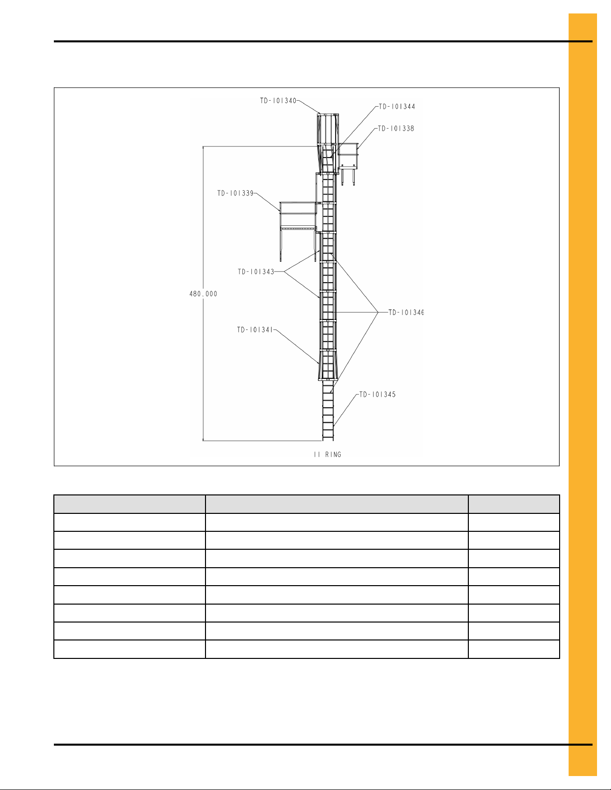
11 Ring Top Dry Platform and Ladder Packages
Figure 1-7 11 Ring Top Dry Package Locations
Table 1-6 11 Ring Top Dry Packages
Callout Description Quantity
TD-101388 Top Dry Eave platform 1
TD-101339 Top Dry Storage Chamber Platform 1
TD-10140 TopDry Platform Cage Package 1
TD-101341 4’ Bell Package 1
TD-101343 8’ Standard Safety Cage 2
TD-101344 Top Dry Ladder Package (12’) 1
TD-101345 4’ Standard Ladder Package 1
TD-101346 8’ Ladder Package 3
Pneg-1877 Top Dry Ladders, Safety Cage, and Platforms 11
Page 12

Chapter 1 Top Dry Ladder and Platform Layouts
12 Ring Top Dry Platform and Ladder Packages
Figure 1-8 12 Ring Top Dry Package Locations
Table 1-7 12 Ring Top Dry Packages
Callout Description Quantity
TD-101338 Top Dry Eave Platform 1
TD-101339 Top Dry STORAGE CHAMBER PLATFORM 1
TD-101340 Top Dry Platform Cage Package 1
TD-101341 4’ Bell Package 1
TD-101342 4’ Standard Safety Cage 1
TD-101343 8’ Standard Safety Cage 2
TD-101344 Top Dry Ladder Package (12') 1
TD-101346 8' Ladder Package
12 Pneg-1877 Top Dry Ladders, Safety Cage, and Platforms
4
Page 13

2 Ladders
Topics Covered in this Chapter
▪ Ladder Extension Rail Installation
▪ Ladder Section Assembly
▪ Ladder Standoff Bracket Detail
Ladder Extension Rail Installation
All ladder systems that include a safety cage must also include ladder extension rails attached to the top 4'
ladder section.
1. Bolt spacer brackets through the top and bottom set of holes in the top ladder section
2. Attach the extension rails to the spacer brackets aligning the bottom of the extension flush with the
bottom of the top ladder section.
3. Fasten with 5/16" x 3/4" bin bolts.
Figure 2-1 Ladder Extension Rail
Pneg-1877 Top Dry Ladders, Safety Cage, and Platforms 13
Page 14

Chapter 2 Ladders
Ladder Section Assembly
1. Attach two (2) splice plates (LDR-4317) to the ends of both ladder sections, connecting them
together.
2. Fasten with 5/16" x 3/4" bolts. The head of the bolt should be to the inside of the ladder with the
splice plate on the outside.
NOTE: Wind rings must be installed in relation to the ladder rungs leaving a minium of 1–1/2” below a
ladder rung and 4–1/2” above a ladder rung.
Figure 2-2 Ladder Section Assembly
14 Pneg-1877 Top Dry Ladders, Safety Cage, and Platforms
Page 15

Ladder Standoff Bracket Detail
Figure 2-3 Ladder Standoff Bracket Detail
Chapter 2 Ladders
Pneg-1877 Top Dry Ladders, Safety Cage, and Platforms 15
Page 16

NOTES
16 Pneg-1877 Top Dry Ladders, Safety Cage, and Platforms
Page 17

3 Eave Platform
Topics Covered in this Chapter
▪ Eave Platform Mounting Angle Location
▪ Eave Starter Bracket and Ladder Assembly
▪ Eave Platform Assembly
▪ Adjustable Eave Braces
▪ Top Dry Eave Platform Parts
Eave Platform Mounting Angle Location
1. Locate eave platform mounting angles 9-3/8" to the right of the ladder holes.
2. Field drill 3/8” holes on 8” centers into sidewall sheets.
Figure 3-1 Eave Platform Mounting Angles
Pneg-1877 Top Dry Ladders, Safety Cage, and Platforms 17
Page 18

Chapter 3 Eave Platform
Figure 3-2 Platform Support Mounting Location
18 Pneg-1877 Top Dry Ladders, Safety Cage, and Platforms
Page 19

Chapter 3 Eave Platform
Eave Starter Bracket and Ladder Assembly
1. The ladder starter brackets must be located in line with the top horizontal seam.
2. Attach ladder to the starter brackets using the hole located 1" from top of the ladder.
3. Field drill the second 3/8" hole for the starter bracket on the ladder 2" below the hole 1" from the top
of the ladder.
4. All standoff brackets must be installed every 44" and attached to each 4' ladder section required.
5. Use 5/16" x 3/4" bin bolts for these connections.
Figure 3-3 Eave Starter Bracket for Ladders
Pneg-1877 Top Dry Ladders, Safety Cage, and Platforms 19
Page 20

Chapter 3 Eave Platform
Eave Platform Assembly
1. Attach the platform to the platform support using 5/16" x 3/4" bolts and nuts.
2. Position all the vertical angles in place, making sure to orient the vertical entrance angle to the left
front corner of the platform.
3. Attach front and side handrails using 5/16" x 3/4" bolts and nuts.
20 Pneg-1877 Top Dry Ladders, Safety Cage, and Platforms
Page 21

Chapter 3 Eave Platform
Adjustable Eave Braces
An eave adjustable brace is comprised of one large diameter tube and two (2) smaller tubes.
1. Slide the smaller tubes inside the larger tube and attach one smaller tube to the top of the ladder
extension rail.
2. Adjust the other smaller tube so the bottom of the flattened tube reaches the roof panel.
3. Field drill four (4) 5/16" holes through both large and small tubes and bolt together using 1/4" x 1-1/2"
bolts and nuts to prevent the adjustable braces from sliding.
Pneg-1877 Top Dry Ladders, Safety Cage, and Platforms 21
Page 22

Chapter 3 Eave Platform
Top Dry Eave Platform Parts
Figure 3-4 Top Dry Eave Platform Parts
22 Pneg-1877 Top Dry Ladders, Safety Cage, and Platforms
Page 23

Table 3-1 Top Dry Eave Platform Parts
Chapter 3 Eave Platform
Component
LS-6705 Platform Mounting Angle
LS-369
LS-370 Support Angle
LS-373 Platform
LS-371 Platform Vertical Angle
LS-6621
Ls-294
LS-295
LS-6776 Safety Cage Hoop Adapter Angle
LS-6775 Safety Cage Extension Angle
S-275 5/16” x 3/4” YDP Grade 5 Hex Head Bin Bolt
S-277 5/16” x 1–1/4” YDP Grade 5 Hex Head Bin Bolt
S-396 5/16” Hex Nut
Description
Brace Angle
Vertical Entrance Angle Extension
End Handrail Angle
Front Handrail Angle
Pneg-1877 Top Dry Ladders, Safety Cage, and Platforms 23
Page 24

NOTES
24 Pneg-1877 Top Dry Ladders, Safety Cage, and Platforms
Page 25

4 Storage Chamber Platform
Topics Covered in this Chapter
▪ Storage Chamber Platform Assembly
▪ Storage Chamber Platform Parts
▪ Extension Angle Hole Detail
Storage Chamber Platform Assembly
1. Use 5/16” x 3/4” truss head bolts and nuts for all connections.
2. Mount platform mounting angles to the side of the bin located 9–3/8” from the ladder and 56–1/4”
apart.
3. Attach the platform supports and diagonal supports to the mounting angles.
4. Attach the three floor braces to the platform supports.
5. Attach the platform floor and toe boards simultaneously to the floor braces.
6. Bolt the vertical entrance angle to the platform floor, toe plate, and platform support.
7. Bolt the handrail posts to the platform floor and toe plates.
8. Attach the handrails to the vertical posts.
Figure 4-1 Platform Support Details
Pneg-1877 Top Dry Ladders, Safety Cage, and Platforms 25
Page 26

Chapter 4 Storage Chamber Platform
Figure 4-2 Assembled Platform
Storage Chamber Platform Parts
Figure 4-3 Top Dry Storage Chamber Platform Parts
26 Pneg-1877 Top Dry Ladders, Safety Cage, and Platforms
Page 27

Table 4-1 Top Dry Storage Chamber Platform Parts
Chapter 4 Storage Chamber Platform
Component
LS-6703 SINGLE PIECE PLATFORM FLOOR
LS-371 PLATFORM VERTICAL ANGLE
LS-6621 VERTICAL ENTRANCE ANGLE EXT ST
LS-6698 EXT STIFF PLATFORM SPPRT ANGLE
LS-6699 DIAG SUPPRT ANGLE LEFT HAND
LS-6700 DIAG SPRT ANGLE RIGHT HAND EXT
LS-6701 PLATFORM FLOOR BRACE
LS-6702 58" HANDRAIL TOPDRY ACESS PLTF
LS-6775 Safety Cage Extension Angle
LS-6776 Safety Cage Hoop Adapter Angle
TDP-5002 30" HANDRAIL
TDP-5008N SIDEWALL BRACE-2.66 PLATFRM
TDP-5011 PLATFORM TOE PLATE
S-275 BOLT, HHBIN 5/16-18 X 3/4 YDP GR5
S-396 NUT, HEX 5/16-18 YDP GR2
Description
Pneg-1877 Top Dry Ladders, Safety Cage, and Platforms 27
Page 28

Chapter 4 Storage Chamber Platform
Extension Angle Hole Detail
28 Pneg-1877 Top Dry Ladders, Safety Cage, and Platforms
Page 29

5 Safety Cage Assembly
Topics Covered in this Chapter
▪ Adapter Assembly Detail
▪ Connection Detail
▪ Intermediate Safety Cage Hoop Assembly
▪ Safety Cage Hoop Bracket Detail
▪ Safety Cage Vertical Supports
▪ Safety Cage Sections
▪ 48” Safety Cage Bell Section
Adapter Assembly Detail
Platform to safety cage adapter overlap detail for 24’ diameter through 36’ diameter bins.
Connection Detail
Use to determine the proper holes to use when attaching the safety cage hoop adapters to the safety cage
hoop adjuster plate for the bin diameter used.
Pneg-1877 Top Dry Ladders, Safety Cage, and Platforms 29
Page 30

Chapter 5 Safety Cage Assembly
Intermediate Safety Cage Hoop Assembly
1. Use 5/16" x 3/4" bolt with the head of the bolts to the inside of the safety cage.
2. Attach the safety cage hoop brackets to the ladder section.
3. Take the safety cage hoop adjuster plates and bolt them onto the extension angle.
4. Bolt the safety cage hoop adapters and safety cage hoop halves together using the proper holes
depending on the diameter of the grain bin.
5. Bolt these assemblies to the safety cage hoop brackets and safety cage hoop adjuster plates, tighten
bolts as you go.
6. The bottom assembly requires two (2) hoop halves and will be positioned just below the platform.
7. Use the safety cage hoop adjuster angle to secure the two (2) hoop half assembly to the vertical
entrance angle on the platform assembly.
30 Pneg-1877 Top Dry Ladders, Safety Cage, and Platforms
Page 31

Safety Cage Hoop Bracket Detail
Figure 5-1 Safety Cage Hoop Bracket Detail
Chapter 5 Safety Cage Assembly
Pneg-1877 Top Dry Ladders, Safety Cage, and Platforms 31
Page 32

Chapter 5 Safety Cage Assembly
Safety Cage Vertical Supports
1. After all three (3) hoop assemblies are in place, attach the 48" vertical supports from hoop assembly
to hoop assembly, as shown in Figure 8Q This requires ten (10) supports, five (5) between each set
of hoops.
2. The second set of vertical supports must be bent at the flat area to allow for the tapering of the
bottom hoop assembly. Use 5/16" x 3/4" bolts (unless otherwise noted) with the head of the bolt to
the inside of the safety cage.
Safety Cage Sections
1. Attach the vertical support pieces to the existing hoop halves above using the 5/16" x 3/4" bolts and
nuts, with the heads on the inside of the cage.
2. Fasten two (2) hoop halves together and bolt to other end of vertical supports.
3. Attach safety cage hoop brackets to ladder.
4. Once safety cage hoop brackets have been installed, attach cage hoop halves and tighten bolts.
Repeat installation for each safety cage required.
32 Pneg-1877 Top Dry Ladders, Safety Cage, and Platforms
Page 33

Chapter 5 Safety Cage Assembly
48” Safety Cage Bell Section
1. Attach the vertical supports to the hoop half assembly from the final safety cage installation using 5/
16" x 3/4" bolts and nuts (with the heads on the inside of the cage).
2. Assemble the special bell safety cage hoop halves and attach to other end of vertical supports.
3. The vertical support must be bent at the flat area to allow for the angle of the bell section. Attach the
safety cage hoop brackets to the ladder as described in Intermediate Safety Cage Hoop Assembly,
page 30.
4. Once the safety cage hoop brackets are installed, attach the bell safety cage hoop half assembly to
the safety cage brackets and tighten bolts.
5. Once the safety cage hoop brackets are installed, attach the bell safety cage hoop half assembly to
the safety cage brackets and tighten bolts.
NOTE: The safety cage bell section is to be used at the point of termination of the safety cage and should
be just above the base platform (generally 7' to 8').
Pneg-1877 Top Dry Ladders, Safety Cage, and Platforms 33
Page 34

NOTES
34 Pneg-1877 Top Dry Ladders, Safety Cage, and Platforms
Page 35

GSI Group, LLC Limited Warranty
GSI Group, LLC Limited Warranty
The GSI Group, LLC (“GSI”) warrants products which it manufactures to be free of defects in materials and workmanship
under normal usage and conditions for a period of 12 months after sale to the original end-user or if a foreign sale, 14
months from arrival at port of discharge, whichever is earlier. The end-user’s sole remedy (and GSI’s only obligation) is to
repair or replace, at GSI’s option and expense, products that in GSI’s judgment, contain a material defect in materials or
workmanship. Expenses incurred by or on behalf of the end-user without prior written authorization from the GSI Warranty
Group shall be the sole responsibility of the end-user.
Warranty Extensions:
The Limited Warranty period is extended for the following products:
Product Warranty Period
Performer Series Direct Drive Fan Motor 3 Years
AP Fans and Flooring
Cumberland
Feeding/Watering
Systems
Grain Systems Grain Bin Structural Design
Grain Systems
Farm Fans
Zimmerman
All Fiberglass Housings
All Fiberglass Propellers
Feeder System Pan Assemblies
Feed Tubes (1-3/4" and 2.00")
Centerless Augers
Watering Nipples
Portable and Tower Dryers
Portable and Tower Dryer Frames and Internal Infrastructure †
Lifetime
Lifetime
5 Years **
10 Years *
10 Years *
10 Years *
5 Years
2 Years
5 Years
* Warranty prorated from list price:
0 to 3 years - no cost to end-user
3 to 5 years - end-user pays 25%
5 to 7 years - end-user pays 50%
7 to 10 years - end-user pays 75%
** Warranty prorated from list price:
0 to 3 years - no cost to end-user
3 to 5 years - end-user pays 50%
† Motors, burner components and
moving parts not included.
Portable dryer screens included.
Tower dryer screens not included.
GSI further warrants that the portable and tower dryer frame and basket, excluding all auger and auger drive components,
shall be free from defects in materials for a period of time beginning on the twelfth (12
and continuing until the sixtieth (60
th
) month from the date of purchase (extended warranty period). During the extended
th
) month from the date of purchase
warranty period, GSI will replace the frame or basket components that prove to be defective under normal conditions of use
without charge, excluding the labor, transportation, and/or shipping costs incurred in the performance of this extended
warranty.
Conditions and Limitations:
THERE ARE NO WARRANTIES THAT EXTEND BEYOND THE LIMITED WARRANTY DESCRIPTION SET FORTH
ABOVE. SPECIFICALLY, GSI MAKES NO FURTHER WARRANTY OF ANY KIND, EXPRESS OR IMPLIED, INCLUDING,
WITHOUT LIMITATION, WARRANTIES OF MERCHANTABILITY OR FITNESS FOR A PARTICULAR PURPOSE OR
USE IN CONNECTION WITH: (I) PRODUCT MANUFACTURED OR SOLD BY GSI OR (II) ANY ADVICE, INSTRUCTION,
RECOMMENDATION OR SUGGESTION PROVIDED BY AN AGENT, REPRESENTATIVE OR EMPLOYEE OF GSI
REGARDING OR RELATED TO THE CONFIGURATION, INSTALLATION, LAYOUT, SUITABILITY FOR A PARTICULAR
PURPOSE, OR DESIGN OF SUCH PRODUCTS.
GSI shall not be liable for any direct, indirect, incidental or consequential damages, including, without limitation, loss of
anticipated profits or benefits. The sole and exclusive remedy is set forth in the Limited Warranty, which shall not exceed
the amount paid for the product purchased. This warranty is not transferable and applies only to the original end-user. GSI
shall have no obligation or responsibility for any representations or warranties made by or on behalf of any dealer, agent or
distributor.
GSI assumes no responsibility for claims resulting from construction defects or unauthorized modifications to products
which it manufactured. Modifications to products not specifically delineated in the manual accompanying the equipment at
initial sale will void the Limited Warranty.
This Limited Warranty shall not extend to products or parts which have been damaged by negligent use, misuse, alteration,
accident or which have been improperly/inadequately maintained. This Limited Warranty extends solely to products manufactured by GSI.
Prior to installation, the end-user has the responsibility to comply with federal, state and local codes which apply to the location and installation of products manufactured or sold by GSI.
9101239_1_CR_rev7.DOC (revised July 2009)
Pneg-1877 Top Dry Ladders, Safety Cage, and Platforms 35
Page 36

This equipment shall be installed in accordance with the
current installation codes and applicable regulations
which should be carefully followed in all cases.
Authorities having jurisdiction should be consulted
before installations are made.
Copyright © 2012 by GSI Group
Printed in the USA
GSI Group
1004 E. Illinois St.
Assumption, IL 62510-0020
Phone: 1-217-226-4421
Fax: 1-217-226-4420
www.gsiag.com
CN #209319
 Loading...