

Page 1
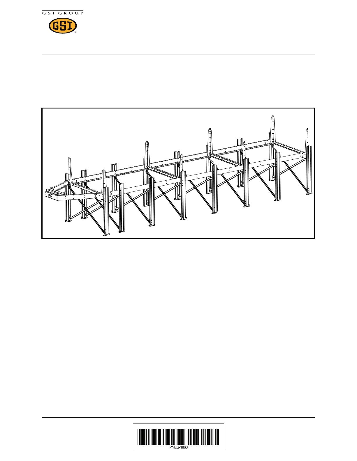
Cross Brace Installation for
PNEG-1860
1004 East Illinois Street • Assumption, IL 62510 • 1–217–226–4421
48” Leg Packages
Cross Brace Installation for 48 Inch Leg Packages
Cross braces are required for dryer legs 48 Inches (1.22 m).
1. After leg stands are installed and secured, cross braces must be installed between the leg
stands. Refer to PNEG-546 for leg installation.
Date:2–16–12
Printed in the U.S.A.
Copyright 2012 by GSI Group
www.gsiag.com
PNEG-1860
Page 1
Page 2

Cross Brace Installation for
PNEG-1860
1004 East Illinois Street • Assumption, IL 62510 • 1–217–226–4421
48” Leg Packages
Standard Cross Brace Installation Hole Locations
This installation is for all connections except for the connection at the leg stands at the hitch
bracket location.
1. For all typical cross brace installations, use the holes in the leg stand X-brace bracket (A)
that are located to the outside of the bracket closest to the legs for all connections.
Callout Description
A Install cross braces using these holes for typical brace
installation
Date:2–16–12
Printed in the U.S.A.
Copyright 2012 by GSI Group
www.gsiag.com
PNEG-1860
Page 2
Page 3

Cross Brace Installation for
PNEG-1860
1004 East Illinois Street • Assumption, IL 62510 • 1–217–226–4421
48” Leg Packages
Standard Cross Brace Installation to Leg Stands
1. Install the leg stand X-brace bracket (B) to the tops and bottoms of the dryer leg stands
using bolts (C) and nuts (D). Brackets (B) should be installed so the large flat surface is
towards the hitch end of the dryer.
2. Attach the flat sides of the leg stand X-braces (A) between two legs from an upper and a
lower leg stand x-brace bracket (B). Make sure to use the bolt hole locations indicated for
the typical cross brace installation and fasten with bolts (C) and nuts (D).
3. The flat sides of the leg stand X-braces (A) will cross each other in the center, fasten the
cross braces together at this point with a bolt (C) and nut (D).
Callout Part Number Description
A D01–1773 Leg Stand X-Brace
B D01–1772 Leg Stand X-Brace Bracket
C S-7927 3/8”-16 x 1” YDP Grade 8 Flange Bolt
D S-968 3/8”-16 Grade 5 Wide Flange Nut
Date:2–16–12
Printed in the U.S.A.
Copyright 2012 by GSI Group
www.gsiag.com
PNEG-1860
Page 3
Page 4

Cross Brace Installation for
PNEG-1860
1004 East Illinois Street • Assumption, IL 62510 • 1–217–226–4421
48” Leg Packages
Hitch Cross Brace Installation Hole Locations (HITCH
BRACKET LOCATION ONLY)
This installation is for connecting the leg stands at the hitch bracket location.
1. For connections at the hitch bracket location, use the holes in the leg stand X-brace bracket
(A) that are located to the inside of the bracket farthest from the legs for all connections.
Callout Description
A Install cross braces using these holes for connections to the
legs at the hitch.
Date:2–16–12
Printed in the U.S.A.
Copyright 2012 by GSI Group
www.gsiag.com
PNEG-1860
Page 4
Page 5

Cross Brace Installation for
PNEG-1860
1004 East Illinois Street • Assumption, IL 62510 • 1–217–226–4421
48” Leg Packages
Cross Brace Installation to Legs at HITCH BRACKET
LOCATION
1. Install the leg stand X-brace bracket (B) to the tops and bottoms of the dryer leg stands
using bolts (C) and nuts (D). Brackets (B) should be installed so the large flat surface is
towards the hitch end of the dryer.
2. Attach the flat sides of the leg stand X-braces (A) between two legs from an upper and a
lower leg stand x-brace bracket (B). Make sure to use the bolt hole locations indicated for
the hitch cross brace installation and fasten with bolts (C) and nuts (D).
3. The flat sides of the leg stand X-braces (A) will cross each other in the center, fasten the
cross braces together at this center point with a bolt (C) and nut (D).
Callout Part Number Description
A D01–1773 Leg Stand X-Brace
B D01–1772 Leg Stand X-Brace Bracket
C S-7927 3/8”-16 x 1” YDP Grade 8 Flange Bolt
D S-968 3/8”-16 Grade 5 Wide Flange Nut
Date:2–16–12
Printed in the U.S.A.
Copyright 2012 by GSI Group
www.gsiag.com
PNEG-1860
Page 5
Page 6

1004 East Illinois Street • Assumption, IL 62510 • 1–217–226–4421
PNEG-1860
NOTES
Cross Brace Installation for
48” Leg Packages
Date:2–16–12
Printed in the U.S.A.
Copyright 2012 by GSI Group
www.gsiag.com
PNEG-1860
Page 6
 Loading...