

Page 1

PNEG-1859
2.66" Corrugation 135' Diameter
Tank with 50 PSF Snow Roof
Construction Manual
PNEG-1859
Date: 06-29-12
Page 2

All information, illustrations, photos and specifications in this manual are based on the latest
information available at the time of publication. The right is reserved to make changes at any
time without notice.
2 PNEG-1859 2.66" Corrugation 135' Diameter Tank with 50 PSF Snow Roof
Page 3

Table of Contents
Contents
Chapter 1 Introduction .......................................................................................................................................... 4
Chapter 2 Safety ..................................................................................................................................................... 5
Safety Guidelines .................................................................................................................................. 5
General Safety Statement ..................................................................................................................... 6
Safety Instructions ..................... ... .... .......................................... ... ... ..................................................... 7
Safety Sign-Off Sheet ........................................................................................................................... 9
Proper Storage of Grain Bin/Silo Materials Prior to Construction ....................................................... 10
General Information ............................................................................................................................ 11
Construction Procedures and Lifting Jack Usage ............................................................................... 12
Chapter 3 Safety Decals ...................................................................................................................................... 13
Roof Damage Warning and Disclaimer ............................................................................................... 13
Chapter 4 Decal Sheet Placement ...................................................................................................................... 16
Chapter 5 Bolting Requirements ........................................................................................................................ 17
Stiffener to Sidewall Connections 3 Post Tanks .............................................. ... .... ... ......................... 18
Bolting and Hardware Requirements .................................................................................................. 19
Chapter 6 Caulking Details ................................................................................................................................. 26
Caulking Detail for Standard (Non-Laminated) Sheets ....................................................................... 26
Caulking Detail for Laminated Quad Pattern Sheets .......................................................................... 27
Caulking Detail for Laminated Figurate Pattern Sheets ...................................................................... 28
Chapter 7 Installation .......................................................................................................................................... 30
Base Angle Installation ........................................................................................................................ 30
Anchor Bolt Detail ............................................................................................................................... 31
Chapter 8 2.66" Commercial Tank Stiffener Instructions (Outside Stiffened) ............................................... 32
2.66" Commercial Tank Stiffener Instructions Outside Stiffened Only ................................................ 32
3 Stiffeners per Sidewall Sheet ........................................................................................................... 46
Wind Ring Assembly .................................... .... ... ... .......................................... ... .... ... ......................... 47
Chapter 9 2.66" Commercial Tank Roof Instructions ...................................... ... .... .......................................... 48
Roof Beam Stiffener Sidewall Attachment .......................................................................................... 48
Roof Beam Stiffener and Bracket Attachment .................................................................................... 48
Eave Clip Attachment .......................................................................................................................... 48
Tension Coupler and Tension Plate Connection ................................................................................. 49
Center Collar Placement ............................................................................................................... ... ... 50
Roof Beam Splice ............................................................................................................................... 50
Roof Beam to Tension Coupler and Center Collar ........... ... ... .... ... ... ... ... .... ... ... ... ................................ 51
Purlin Attachment to Roof Beams ....................................................................................................... 52
X-Bracing Layout ....................... ... .... ... .......................................... ... ... ............................................. ... 56
Z-Collar Assembly ............................ ... ... .......................................... ... ... ............................................. 58
Lower Flange Brace Instructions ................................................................................................... ... ... 60
Lower Roof Panel Attachment ............................................................................................................ 61
Upper Roof Panel Attachment ............................................................................................................ 63
Chapter 10 2.66" Commercial Tank Accessories Installation .......................................................................... 65
Roof Vent Assembly ................................... .... ... ... .......................................... ... .... ............................ 65
Roof Exhauster Placement ................................ ... ... .... ... ... ... .... ... ... ... ... .... ... ... ... .... ... ......................... 68
Safety Ring Placement ...................................................................................................................... 70
Temperature Cable Layout ......................................................................................................
Temperature Cable Bracket (CRP-6205) Assembly Instructions (Optional) ..................................... 73
Inside Ladder Installation ................................................................................................................... 74
135' 2 Ring Door Instructions ............................................................................................................ 79
.......... 71
Chapter 11 Warranty ............................................................................................................................................ 89
PNEG-1859 2.66" Corrugation 135' Diameter Tank with 50 PSF Snow Roof 3
Page 4

1. Introduction
READ THIS MANUAL carefully to learn how to properly use and install equipment. Failure to do so could
result in personal injury or equipment damage.
INSPECT the shipment immediately upon arrival. The customer is responsible for ensuring that all
quantities are correct. The customer should report and note any damage or shortage on the bill of lading
to justify their claim to the transport company.
THIS MANUAL SHOULD BE CONSIDERED a permanent part of your equipment and should be easily
accessible when needed.
This warranty provides you the assurance that the company will back its products when defects appear
within the warranty period. In some circumstances, the company also provides field improvements, often
without charge to the customer, even if the product is out of warranty. Should the equipment be abused
or modified to change its performance beyond the factory specifications, the warranty will become void
and field improvements may be denied.
4 PNEG-1859 2.66" Corrugation 135' Diameter Tank with 50 PSF Snow Roof
Page 5
2. Safety
DANGER
WARNING
CAUTION
NOTICE
This is the safety alert symbol. It is used to alert you
to potential personal injury hazards. Obey all safety
messages that follow this symbol to avoid possible
injury or death.
WARNING indicates a hazardous situation which, if not
avoided, could result in death or serious injury.
CAUTION, used with the safety alert symbol, indicates a
hazardous situation which, if not avoided, could result in
minor or moderate injury.
NOTICE is used to address practices not related to
personal injury.
DANGER indicates a hazardous situation which, if not
avoided, will result in death or serious injury.
Safety Guidelines
This manual contains information that is important for you, the owner/operator, to know and understand.
This information relates to protecting personal safety and preventing equipment problems. It is the
responsibility of the owner/operator to inform anyone operating or working in the area of this equipment
of these safety guidelines. To help you recognize this information, we use the symbols that are defined
below. Please read the manual and pay attention to these sections. Failure to read this manual and its
safety instructions is a misuse of the equipment and may lead to serious injury or death.
PNEG-1859 2.66" Corrugation 135' Diameter Tank with 50 PSF Snow Roof 5
Page 6
2. Safety
This product has sharp edges, which may cause serious injury. To avoid injury, handle
sharp edges with caution and always use proper protective clothing and equipment.
General Safety Statement
Our foremost concern is your safety and the safety of others associated with grain handling equipment.
This manual is to help you understand safe operating procedures and some problems that may be
encountered by the operator and other personnel.
As owner and/or operator, you are responsible to know what requirements, hazards, and precau tions exist
and inform all personnel associated with the equipment or in the area. Safety precautions may be required
from the personnel. Avoid any alterations to the equipment, which may produce a very dangerous
situation, where SERIOUS INJURY or DEATH may occur.
You should consider the location of the bin site relative to power line locations or electrical transmission
equipment. Contact your local power company to review your installation plan or for information
concerning required equipment clearance. Clearance of portable equipment that may be taken to the bin
site should also be reviewed and considered. Any electrical control equipment in contact with the bin
should be properly grounded and installed in accordance with National Electric Code provisions and other
local or national codes.
This product is intended for the use of grain storage only. Any other use is a misuse of the product.
Sidewall bundles or sheets must be stored in a safe manner . The safest method of storing sidewall bundles
is laying horizontally with the arch of the sheet up ward, like a dome. Sidewall sheet s stored on edge must
be secured so that they cannot fall over and cause injury. Use care when handling and moving sidewall
bundles.
Personnel operating or working around equipment should read this manual. This manual must be
delivered with equipment to its owner. Failure to read this manual and its safety instructions is a misuse
of the equipment.
6 PNEG-1859 2.66" Corrugation 135' Diameter Tank with 50 PSF Snow Roof
Page 7
2. Safety
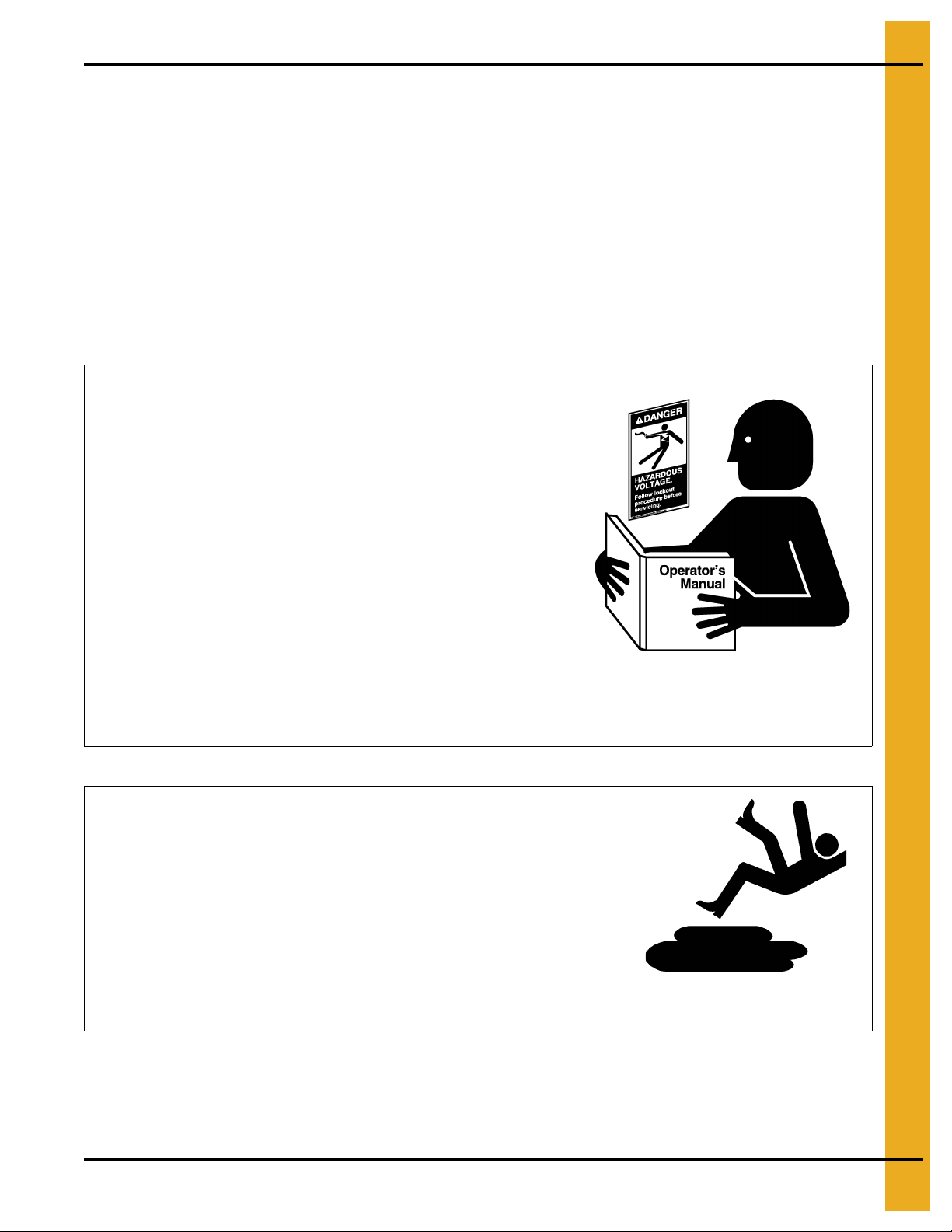
Follow Safety Instructions
Carefully read all safety messages in this manual and
safety signs on your machine. Keep signs in good
condition. Replace missing or damaged safety signs. Be
sure new equipment components and repair parts include
the current safety signs. Replacement safety signs are
available from the manufacturer.
Learn how to operate the machine and how to use controls
properly. Do not let anyone operate without instruction.
Keep your machinery in proper working condition.
Unauthorized modifications to the machine may impair
the function and/or safety and affect machine life.
If you do not understand any part of this manual or need
assistance, contact your dealer.
Read and Understand Manual
Practice Safe Maintenance
Understand service procedures before doing work. Keep area
clean and dry.
Never lubricate, service or adjust machine while it is in operation.
Keep hands, feet, and clothing away from rotating parts.
Keep all parts in good condition and properly installed. Fix
damage immediately . Replace worn or broken p arts. Remove any
built-up grease, oil, and debris.
Maintain Equipment
and Work Area
Safety Instructions
Our foremost concern is your safety and the safety of others associated with this equipment. We want to
keep you as a customer. This manual is to help you understand safe operating procedures and some
problems that may be encountered by the operator and other personnel.
As owner and/or operator, it is your responsibility to know what requirements, hazards, and precautions
exist and to inform all personnel associated with the equipment or in the area. Safety precautions may be
required from the personnel. Avoid any alterations to the equipment. Such alterations may produce a very
dangerous situation where SERIOUS INJURY or DEATH may occur.
This equipment shall be installed in accordance with the current installation codes and applicable
regulations, which should be carefully followed in all cases. Authorities having jurisdiction should be
consulted before installations are made.
PNEG-1859 2.66" Corrugation 135' Diameter Tank with 50 PSF Snow Roof 7
Page 8
2. Safety
Prepare for Emergencies
Be prepared if fire starts.
Keep a first aid kit and fire extinguisher handy.
Keep emergency numbers for doctors, ambulance service,
hospital, and fire department near your telephone.
Keep Emergency Equipment
Quickly Accessible
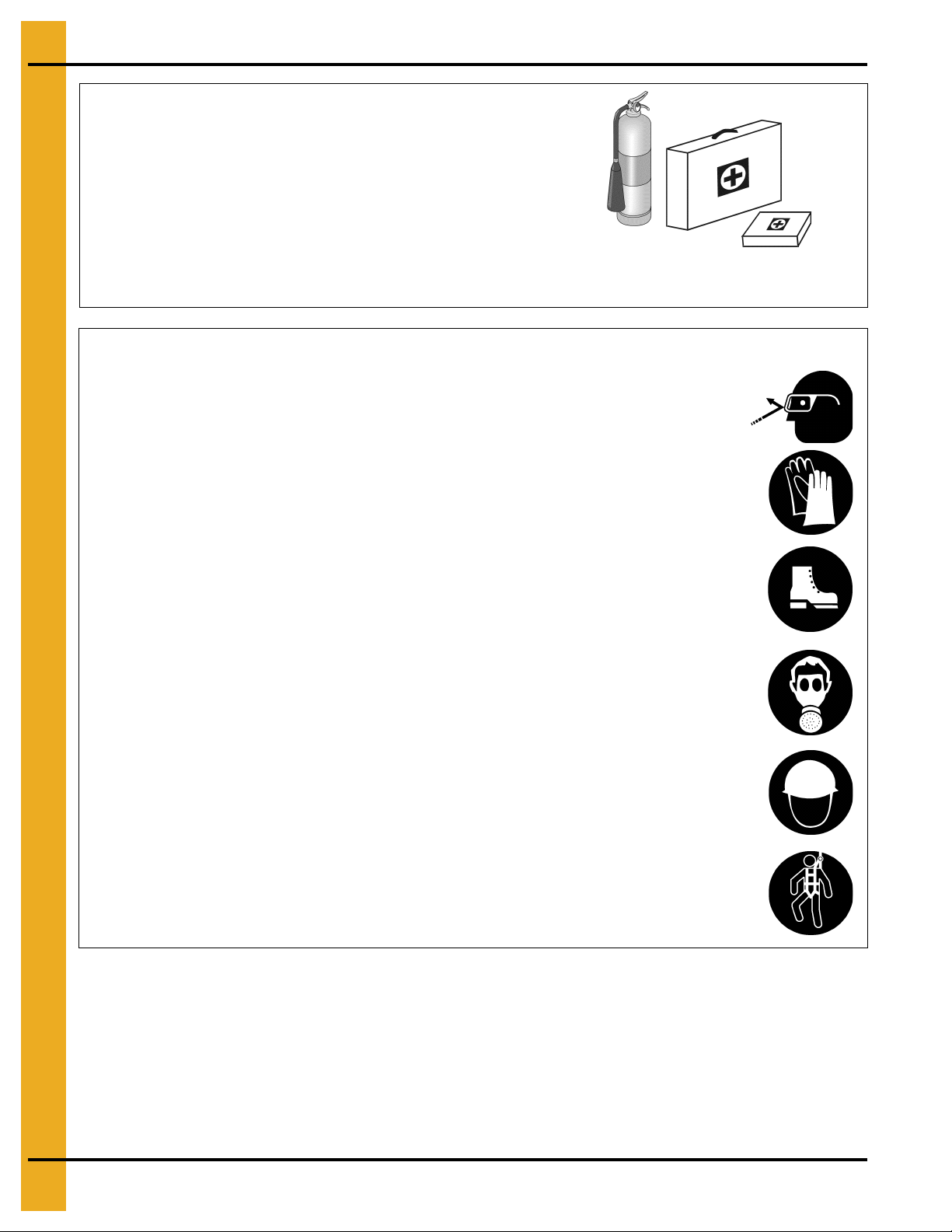
Wear Protective Clothing
Wear close-fitting clothing and safety equipment appropriate
to the job.
Remove all jewelry.
Tie long hair up and back.
Wear safety glasses at all times to protect eyes from debris.
Wear gloves to protect your hands from sharp edges on plastic
or steel parts.
Wear steel-toed boots to help protect your feet from falling
debris. Tuck in any loose or dangling shoestrings.
A respirator may be needed to prevent breathing potentially
toxic fumes and dust.
Wear a hard hat to help protect your head.
Wear appropriate fall protection equipment when working at
elevations greater than six feet (6').
Eye Protection
Gloves
Steel-Toed Boots
Respirator
Hard Hat
Fall Protection
8 PNEG-1859 2.66" Corrugation 135' Diameter Tank with 50 PSF Snow Roof
Page 9

2. Safety
Safety Sign-Off Sheet
As a requirement of O.S.H.A., it is necessary for the employer to train the employee in the safe operating
and safety procedures for this auger. This sign-off sheet is provided for your convenience and personal
record keeping. All unqualified persons are to stay out of the work area at all times. It is strongly
recommended that another qualified person who knows the shut down procedure be in the area in
the event of an emergency.
Date Employee Name Supervisor Name
PNEG-1859 2.66" Corrugation 135' Diameter Tank with 50 PSF Snow Roof 9
Page 10

2. Safety
Proper Storage of Grain Bin/Silo Materials Prior to Construction
Wet storage stain (rust) will develop when closely packed bundles of galvanized material, such as sidewall
and roof sheets, have moisture present. Inspect roof and sidewall bundles on arrival for any moisture. If
moisture is present, it must not be allowed to remain between the she ets. Separate the sheets or panels
immediately and wipe them down. Spray with a light oil or diesel fuel.
If possible, sidewall bundles, roof sheets and other closely packed galvanized materials should be stored
in a dry, climate controlled building. If outdoor storage is unavoidable, the materials should be stored so
that they are raised above the ground and vegetation. Any stacking an d spacing mat erials sho uld not be
corrosive or wet. Be sure to protect materials from the weather, but permit air movement around the
bundles if possible.
Storing roof bundles and sidewall sheets at a slight incline can also help minimize the presence of
moisture. Storing the bundles with the center of the dome up (like an arch) is one option for minimizing
moisture during storage. Sidewall bundles can also be stored on edge but must be secured so that they
do not fall over and cause injury.
If “white rust” or “wet storage stain” occurs, contact the manufacturer imme diately about ways to minimize
the adverse effect upon the galvanized coating.
10 PNEG-1859 2.66" Corrugation 135' Diameter Tank with 50 PSF Snow Roof
Page 11

2. Safety
General Information
Read this manual carefully. This manual will provide instructions on building the sidewall and stiffeners.
You will also need to consult other instructions in building the tank. These include, but may not be
limited to:
A stiffener and sidewall gauge layout chart. If such a chart is not included with this manual, contact GSI.
Roof instructions must be followed. Roof instructions are included in this manual.
Ladders, roof stairs, roof handrails and other products are covered by separate instruction manuals.
Consult the appropriate accessory manual. Inside ladder instructions are included in this manual.
Aeration systems and transitions are to be installed according to the instruct ions provided with the system
or transition.
Anchor bolt placement details are provided in the GSI concrete recommendation manual (PNEG-318).
See this manual.
Tools for Construction
1. Combination wrench set 7/16" to 1".
2. Alignment punches 12" long.
3. Hammer.
4. Screwdrivers - standard and philips.
5. 3/8" Drive socket set and ratchet.
6. 1/2" Drive socket set and ratchet.
7. Nail aprons or tool pouches to hold supplies.
8. Gloves for hand protection.
9. Tape measure.
10. 1/2" Drive electric or pneumatic impact gun.
11. 1/2" Drive impact socket set.
12. Lifting jacks.
13. Center pole roof support.
14. Step ladders.
15. Large C-clamp or welding V-grip for clamping.
Quantities required will depend on the number of workers and size of the bin/silo.
PNEG-1859 2.66" Corrugation 135' Diameter Tank with 50 PSF Snow Roof 11
Page 12

2. Safety
Construction Procedures and Lifting Jack Usage
NOTE: The roof and top ring or 2 rings will be installed prior to the beginning of bin lifting/jacking
procedures. Refer all other procedures on sidewall and stiffener installation prior to the start
of construction.
1. Consider the starting location of the bin, relative to the location of doors and other accessories.
Proper placement of lifting jacks in relationship to anchor bolts could make a difference in final
locations. Note that the sidewall sheets will be staggered.
2. The bin is lifted by the use of lifting jacks. Lifting jacks are used to slowly and evenly lift the bin during
construction. Lifting jacks must be properly sized and designed to carry all dead and live loads and
job site conditions associated with the construction of the bin.
The number of lifting jacks required is best determined by personal experience and expertise.
Factors such as bin size, jack design, construction conditions, support surface, etc., are all to be
considered when deciding how many to use. If in doubt, use one jack on every sheet. The lifting jack
must be adequate to carry all loads. Heavy duty jacks, generally hydraulic or electric powered in the
case of large bins, should be used for commercial installation. All jacks should be secured with
braces or otherwise maintained in a stable condition.
Lifting of the bins should not be done under windy conditions.
Follow the jack manufacturers recommendations on capacity and operations.
3. Lifting brackets must be attached through the stiffener bolt holes. Normally you will need to attach to
at least four (4) bolts per stiffener.
4. Raise the bin just high enough to assemble the next ring. When lifting the bin, all jacks must lift at
an equal rate. Monitor the lift to ensure even lifting is occurring.
5. To the inside of the first ring, bolt the next ring. Be sure to stagger the sheets and select the proper
gauge material.
6. Lower the bin onto the foundation after assembling and tightening bolts on the new ring or rings.
7. Attach stiffeners to the body sheets every two (2) tiers (on the external surface of the bin). You may
want to leave sheets loose to make the attachment of the stiffeners easier.
8. Now re-bolt the lifting brackets to the lowest ring in place thus far. Continue ring additions by
repeating Step 5 and Step 6.
9. Add inside and outside ladders as you continue to raise the bin. (Refer to the manual supplied with
the ladder.)
10. Lower the tank and secure to the foundation before leaving the job site.
11. At the completion of the tank, set stiffeners over the anchor bolts and measure the tank to ensure it
is in a round condition. Consult with GSI for questions on tolerances.
NOTE: For 2 ring doors or vehicle traffic doors special placement issues may apply. Consult the special
instructions provided with 2 ring doors or vehicle traffic doors for these options.
12 PNEG-1859 2.66" Corrugation 135' Diameter Tank with 50 PSF Snow Roof
Page 13
3. Safety Decals
The manufacturer does not warrant any roof damage caused by excess ive v acuum or internal
pressure from fans or other air moving systems. Adequate ventilation and/or “makeup air”
devices should be provided for all powered air handling systems. The manufacturer does not
recommend the use of downward flow systems (suction). Severe roof damage can result from
any blockage of air passages. Running fans durin g high humidity/cold weather conditions can
cause air exhaust or intake ports to freeze.
Roof Damage Warning and Disclaimer
CAUTION!
Excessive vacuum (or pressure) may
damage roof. Use positive aeration
system. Make sure all roof vents are
open and unobstructed. Start roof
fans when supply fans are started.
Do not operate when conditions exist
that may cause roof vent icing.
DC-969
PNEG-1859 2.66" Corrugation 135' Diameter Tank with 50 PSF Snow Roof 13
Page 14
3. Safety Decals
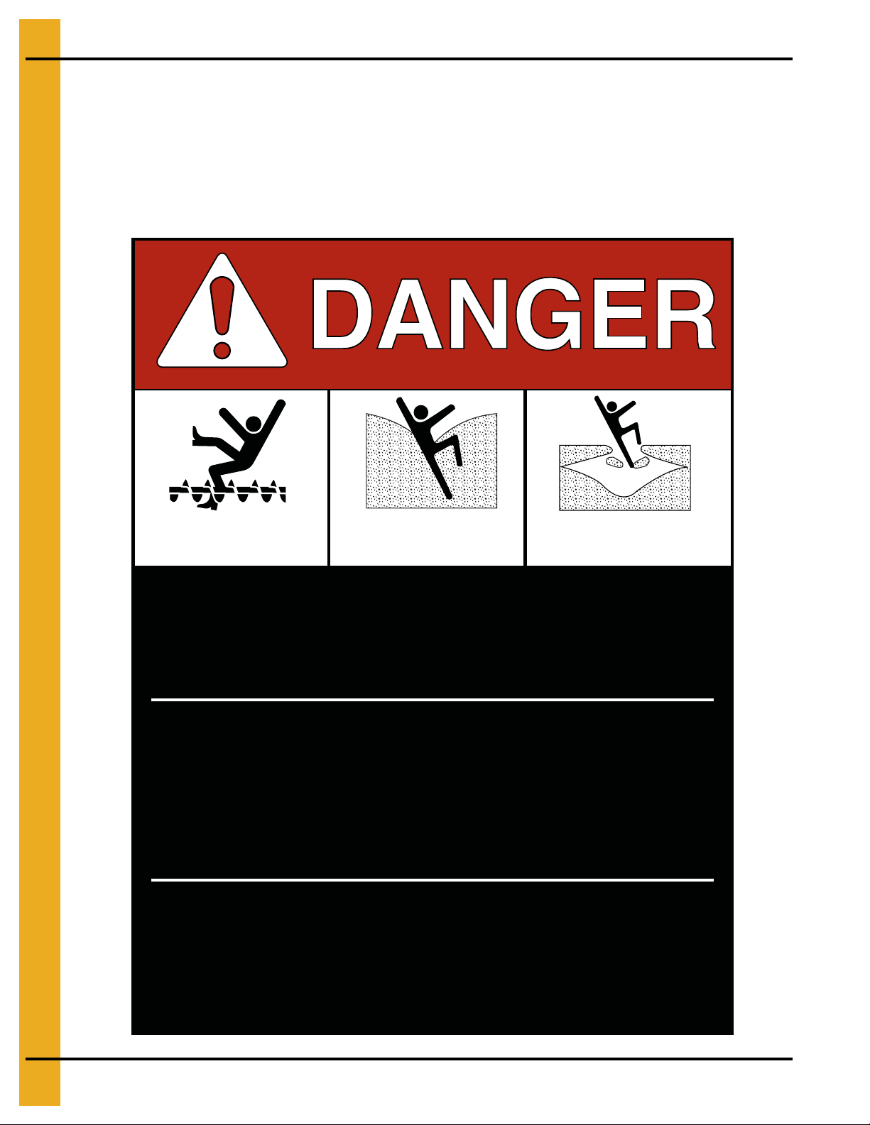
Rotating flighting will
kill or dismember.
Flowing material will
trap and suffocate.
Crusted material will
collapse and suffocate.
Keep clear of all augers.
DO NOT ENTER this bin!
Failure to heed these
warnings will result in
serious injury or death.
If you must enter the bin:
1. Shut off and lock out all power.
2. Use a safety harness and safety line.
3. Station another person outside the bin.
4. Avoid the center of the bin.
5. Wear proper breathing equipment or respirator.
DC-GBC-1A
ATTENTION: The decal shown below should be present on the outside of the door cover of the 2 ring,
24" porthole door cover and the roof manway cover. If a decal has been damaged or is missing in any of
these locations, contact the manufacturer for a free replacement decal.
GSI Decals
1004 E. Illinois St.
Assumption, IL. 62510
Phone: 1-217-226-4421
14 PNEG-1859 2.66" Corrugation 135' Diameter Tank with 50 PSF Snow Roof
Page 15
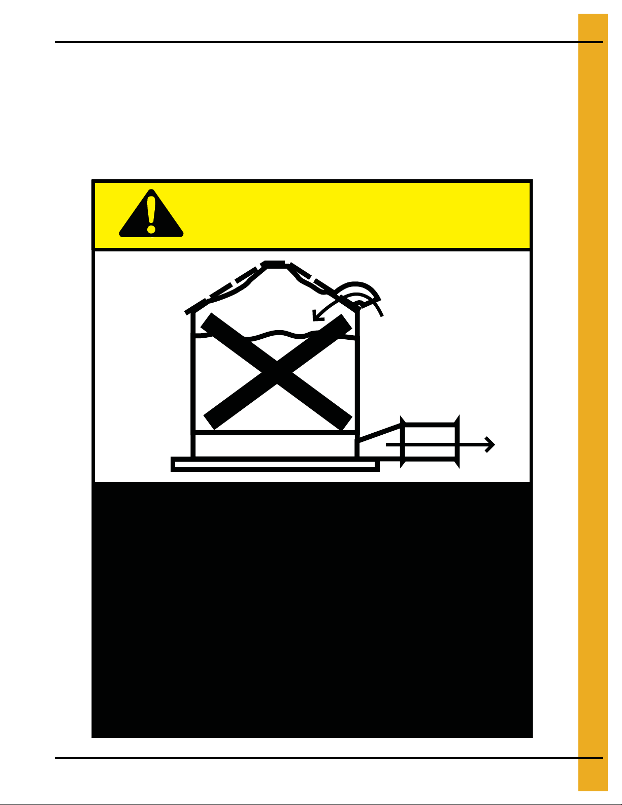
3. Safety Decals
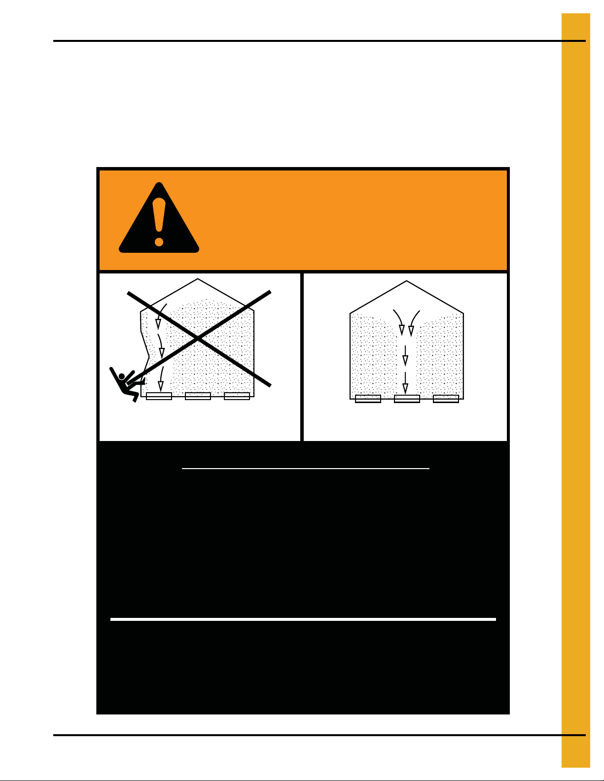
Failure to heed these warnings
could result in serious injury, death,
structural damage or collapse of tank.
1. Use CENTER FLOOR OUTLET ONLY until NO grain
remains above this outlet.
2. Side floor outlets to be used ONLY when above
condition is satisfied.
3. Lock all side floor outlets to avoid accidental
premature use.
4. See manufacturers instructions for proper use of
factory supplied sidedraw (wall) discharge systems.
UNLOADING INSTRUCTIONS:
DC-GBC-2A
WARNING
DON’T
DO
ATTENTION: The decal shown below should be present on the outside of the door cover of the 2 ring,
24" porthole door cover and the roof manway cover. If a decal has been damaged or is missing in any of
these locations, contact the manufacturer for a free replacement decal.
GSI Decals
1004 E. Illinois St.
Assumption, IL. 62510
Phone: 1-217-226-4421
PNEG-1859 2.66" Corrugation 135' Diameter Tank with 50 PSF Snow Roof 15
Page 16
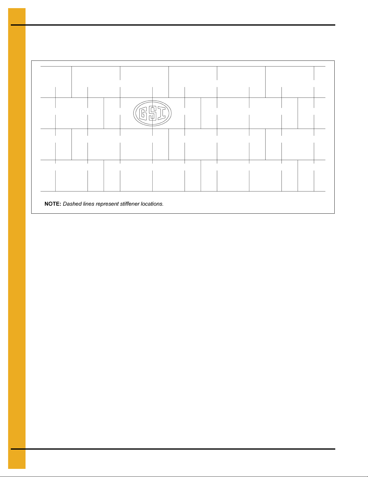
4. Decal Sheet Placement
NOTE: On 3 post bins the top ring is not normally stiffened except for 42' diameter and larger bins with
stiffeners, (one per sidewall panel). Refer stiffener to sidewall attachment detail and specific gauge
sheet for the bin.
Figure 4A 3 Post (Three (3) rows of stiffeners used on each sidewall sheet.)
16 PNEG-1859 2.66" Corrugation 135' Diameter Tank with 50 PSF Snow Roof
Page 17
5. Bolting Requirements
Sidewall Gauge Horizontal Seam Vertical Seam Stiffener to Sidewall Overlap Seam
13Q-10Q
9Q-8Q
6Q-5Q
11QL
10QL
9QL-8QL *
6FL
3/8'' x 1''
(22)
3/8'' x 1''
(22)
3/8'' x 1-1/2''
(22)
3/8'' x 1-1/2''
(22)
3/8'' x 1-1/2''
(22)
3/8'' x 1-1/2''
(24)
7/16'' x 2''
(20)
3/8'' x 1''
(48)
3/8'' x 1''
(48)
3/8'' x 1-1/2''
(48)
3/8'' x 1-1/2''
(48)
3/8'' x 1-1/2''
(48)
7/16'' x 2-1/2'' **
(48)
7/16'' x 2-1/2'' **
(72)
3/8'' x 1''
(12)
3/8'' x 1-1/2''
(12)
3/8'' x 1-1/2''
(12)
3/8'' x 1-1/2''
(12)
3/8'' x 1-1/2'' ***
(24)
3/8'' x 1-1/2'' ***
(24)
3/8'' x 2''
(24)
3/8'' x 1''
(2)
3/8'' x 1-1/2''
(2)
3/8'' x 1-1/2''
(2)
3/8'' x 1-1/2''
(2)
3/8'' x 1-1/2''
(2)
3/8'' x 2''
(6)
7/16'' x 2''
(10)
1. Q - Quad punched sheets.
QL - Laminated quad punched sheets (two (2) sheets of same gauge bolted together).
FL - Laminated figurate (6x) punched sheets (two (2) sheets of same gauge bolted together).
All bolts referenced in this table are bolts with a neoprene washers on the outside of the tank.
No washers are required on the inside of the tank. Refer to the stiffener and splice hardware section
on Page 32 for stiffener connection hardware usage.
2. Before bolting sheets together, apply a single strip of caulking on both sides and 12" on both sides
of top edge. DO NOT CAULK BOTTOM EDGE.
a. When attaching a 6Q sheet to a 8Q sheet, use the 3/8" x 1" bin bolt in the horizontal seam.
b. All base sheets are bolted to the base angle with 3/8" x 1-1/2" bin bolts. (Independent of
sidewall gauge.)
* 6FL to 8QL will be connected using 3/8" x 1-1/2" bolts.
** These bolts require the use of a special 7/16" recessed nuts (S-8479).
*** A 3/8" x 2" Bolt may be needed at first stiffener to sidewall bolt.
Figure 5A Quad (15Q-6FL) Sheet Bolting Detail
PNEG-1859 2.66" Corrugation 135' Diameter Tank with 50 PSF Snow Roof 17
Page 18
5. Bolting Requirements
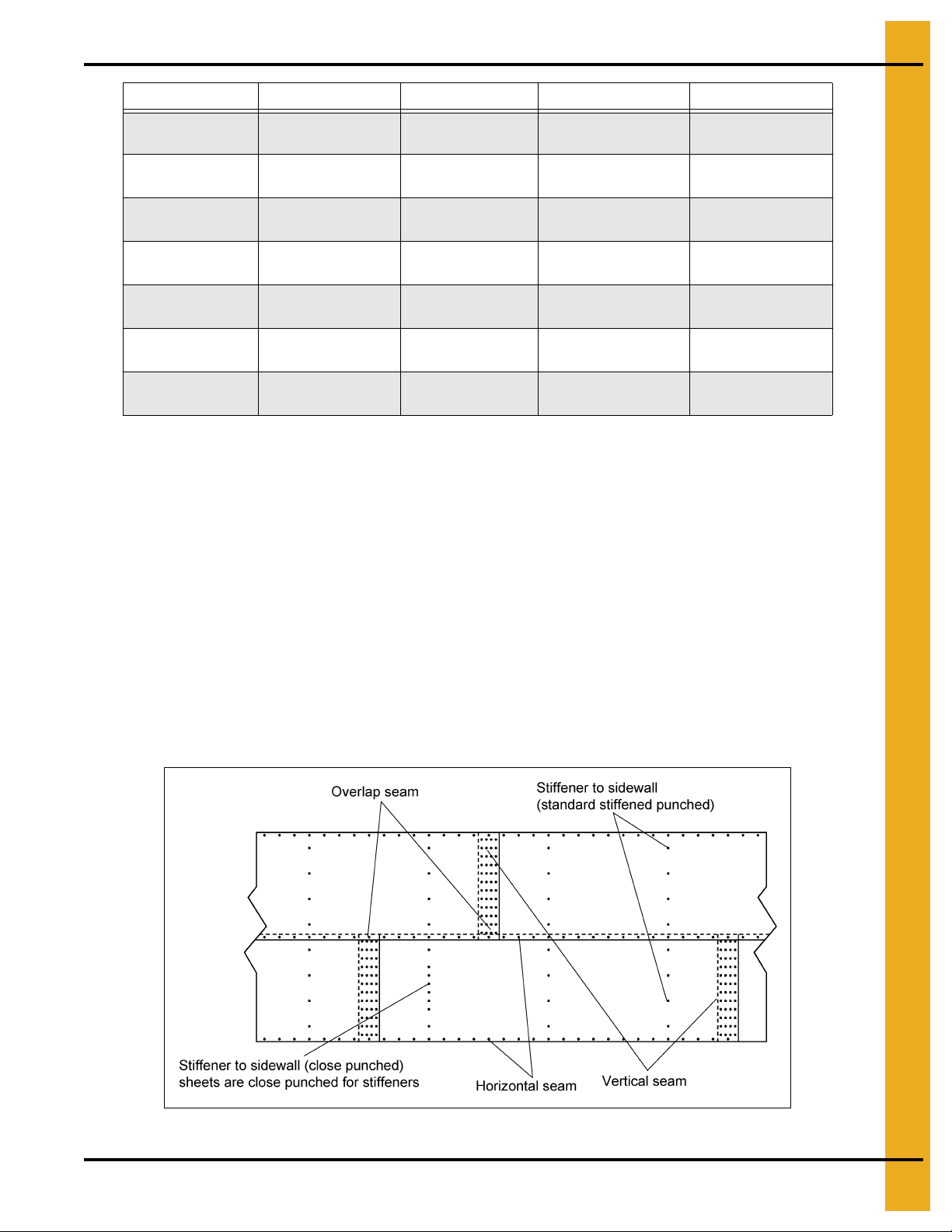
Stiffener to Sidewall Connections 3 Post Tanks
Figure 5B
NOTE: Some locations in the lower regions of the tank utilize close punched sheets where the stiffener
will attach more frequently.
18 PNEG-1859 2.66" Corrugation 135' Diameter Tank with 50 PSF Snow Roof
Page 19
Bolting and Hardware Requirements
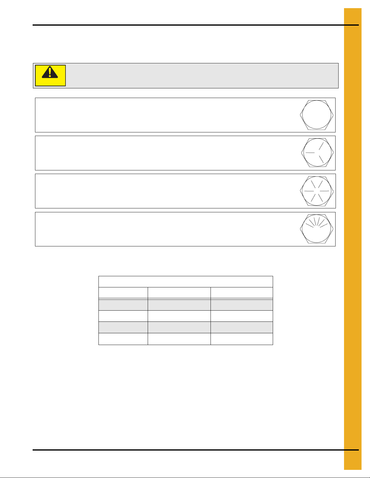
Under no condition shall any other bolts be substituted for those supplied by GSI.
CAUTION
Grade 2 Bolts
Grade 2 bolts are designated with a plain head and are not used in GSI grain bins/silos.
Grade 5 Bolts
Grade 5 bolts are designated by three (3) slash marks on the head. All 5/16" diameter
bolts are to be grade 5 or higher.
Grade 8 Bolts
Grade 8 bolts are designated by six (6) slash marks evenly spaced out around the head
of the bolt.
Grade 8.2 Bolts
Grade 8.2 bolts are designated by six (6) slash marks on the head in a sunrise pattern.
All 3/8" and 7/16" diameter bolts are to be grade 8 or grade 8.2.
Identifying Bolt Grades
5. Bolting Requirements
NOTE: Bolts should not be tightened in excess of the torque specifications in below Chart.
Torque (ft. lbs.)
Bolt Size Minimum Maximum
5/16"-18 15 20
3/8"-16 35 42
7/16"-14 65 72
1/2"-13 95 105
Hardware usage is detailed in the bolting requirement charts on Page 17, stiffener and splice hardware
charts on Page 32 and the bolting and the hardware requirements section.
PNEG-1859 2.66" Corrugation 135' Diameter Tank with 50 PSF Snow Roof 19
Page 20
5. Bolting Requirements
0.3125" x 0.750" Pre-assembled with a steel backed neoprene washer.
This bolt is used to connect horizontal and vertical seams for 14 gauge and thinner sidewall sheets
to each other. It is also used in attaching roof panels to the top sidewall sheet and attaching roof
panels and flashing to the center collar.
0.3125" x 1.250" Pre-assembled with a steel backed neoprene washer.
This bolt is primarily used to connect roof panels together where they overlap. It is also used at the
bottom of the flat bottomed bins to attach the base angle to the sidewall sheet.
Refer to 2.66" commercial tank bolting requirements for complete bolt usage.
20 PNEG-1859 2.66" Corrugation 135' Diameter Tank with 50 PSF Snow Roof
Page 21
5. Bolting Requirements
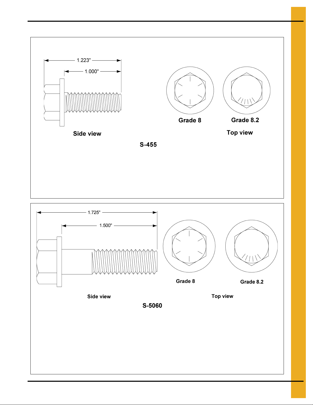
0.375" x 1.000" Pre-assembled with a steel backed neoprene washer.
This bolt is used in horizontal and vertical seams for 13 gauge through 13 gauge laminate sidewall
to attach the sheets to each other. It is also used to attach the stiffener to the sidewall sheet for up to
10 gauge sidewall. It is not used to splice the stiffeners together on the flanges where they conn ect
to each other or the splice plates. These are also used to attach the hopper panels to the hopper
support beam for the NCHT’s.
NOTE: 3/8" x 1-1/2" (S-5060) or 3/8" x 2" (S-9445) Bolts are provided for laminated stiffeners
and splices.
0.375" x 1.500" Pre-assembled with a steel backed neoprene washer.
It is used to connect the stiffener to the sidewall at locations where a splice plate is used to connect
the stiffener and to connect laminated stiffeners to the sidewall sheets. It is also used to bolt
stiffeners to 9 gauge and thicker sidewall. This bolt is also used to bolt horizont al and vertical seams
together on 6 gauge and thicker and some overlap seams. It is only used to attach the stiffener and
the splice plate to the sidewall. The flanges where the stiffener bolts to the splices plates use a
different bolt (one without a sealing washer).
Refer to 2.66" commercial tank bolting requirements for complete bolt usage. (Continued)
PNEG-1859 2.66" Corrugation 135' Diameter Tank with 50 PSF Snow Roof 21
Page 22
5. Bolting Requirements
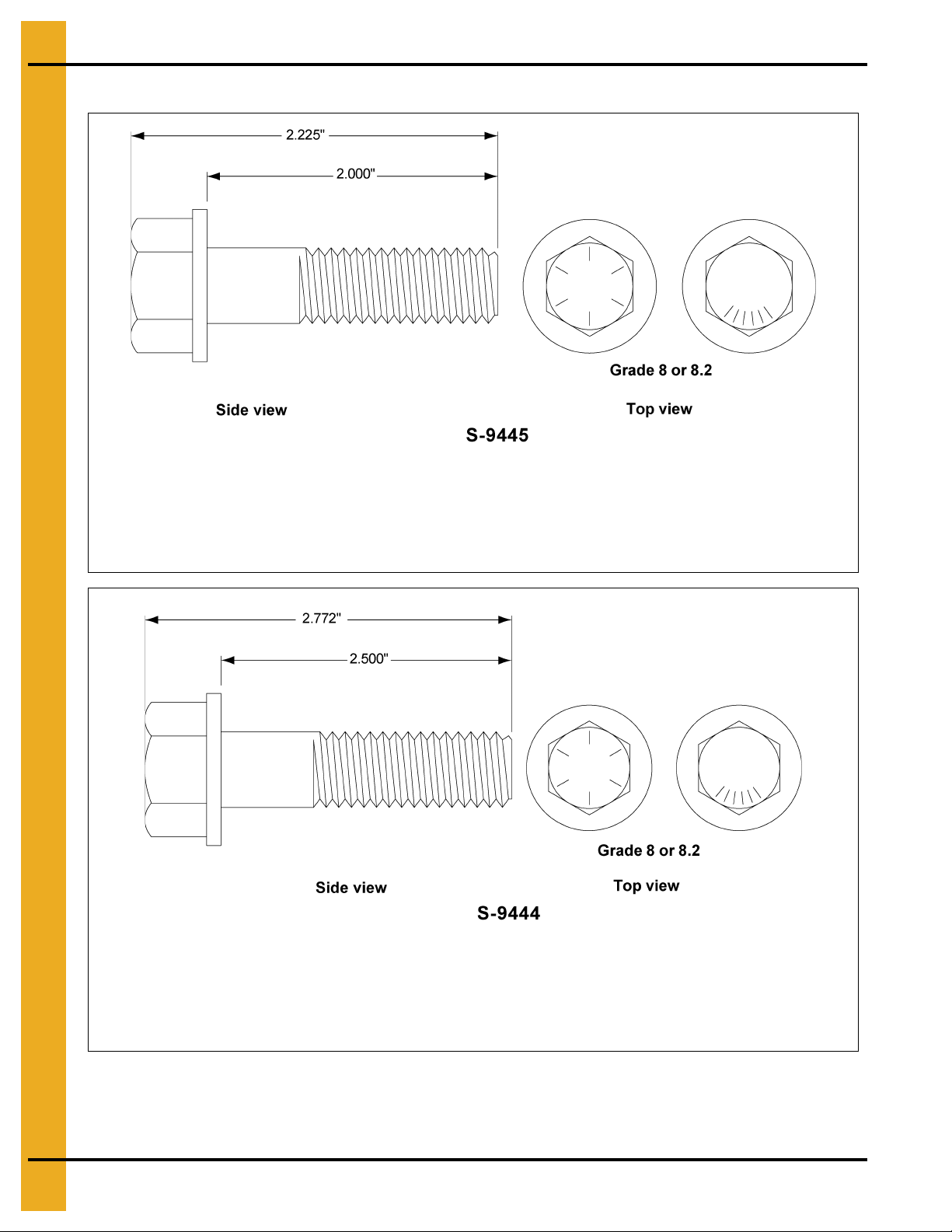
0.375" x 2.000" Pre-assembled steel backed neoprene washer.
This bolt is used in overlapping seams on 8 gauge to 9 gauge laminated sidewall sheets and to
connect 6 gauge laminated rings to one another. It is also used to attach stiffener to sidewall on
6 gauge laminated sidewall sheets.
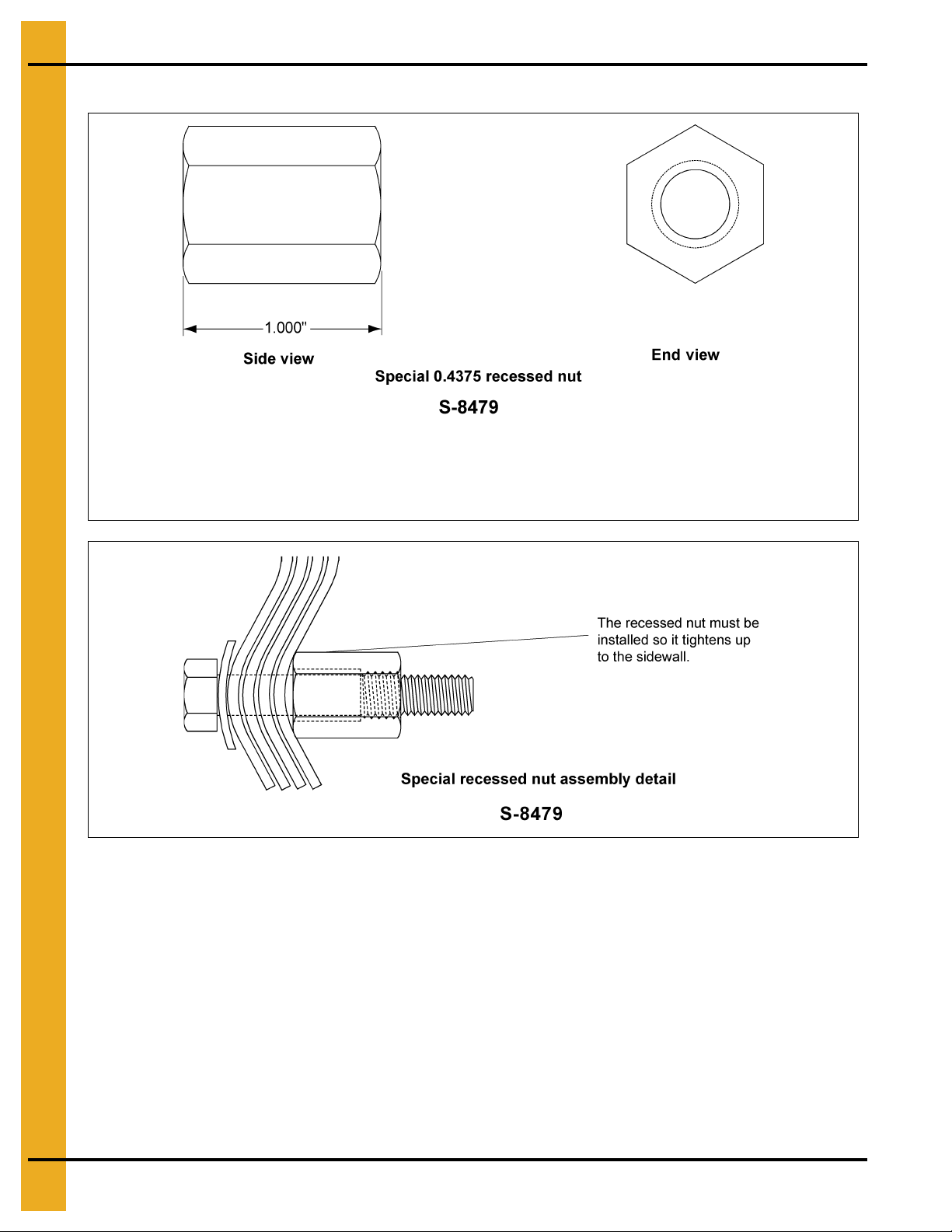
0.4375" x 2.500" Pre-assembled steel backed neoprene washer.
This bolt is used in the vertical seams of 9 gauge laminated and thicker . A special 7/16" nut, S-8479
is required to be used in conjuncture with this bolt.
Refer to 2.66" commercial tank bolting requirements for complete bolt usage. (Continued)
22 PNEG-1859 2.66" Corrugation 135' Diameter Tank with 50 PSF Snow Roof
Page 23
5. Bolting Requirements
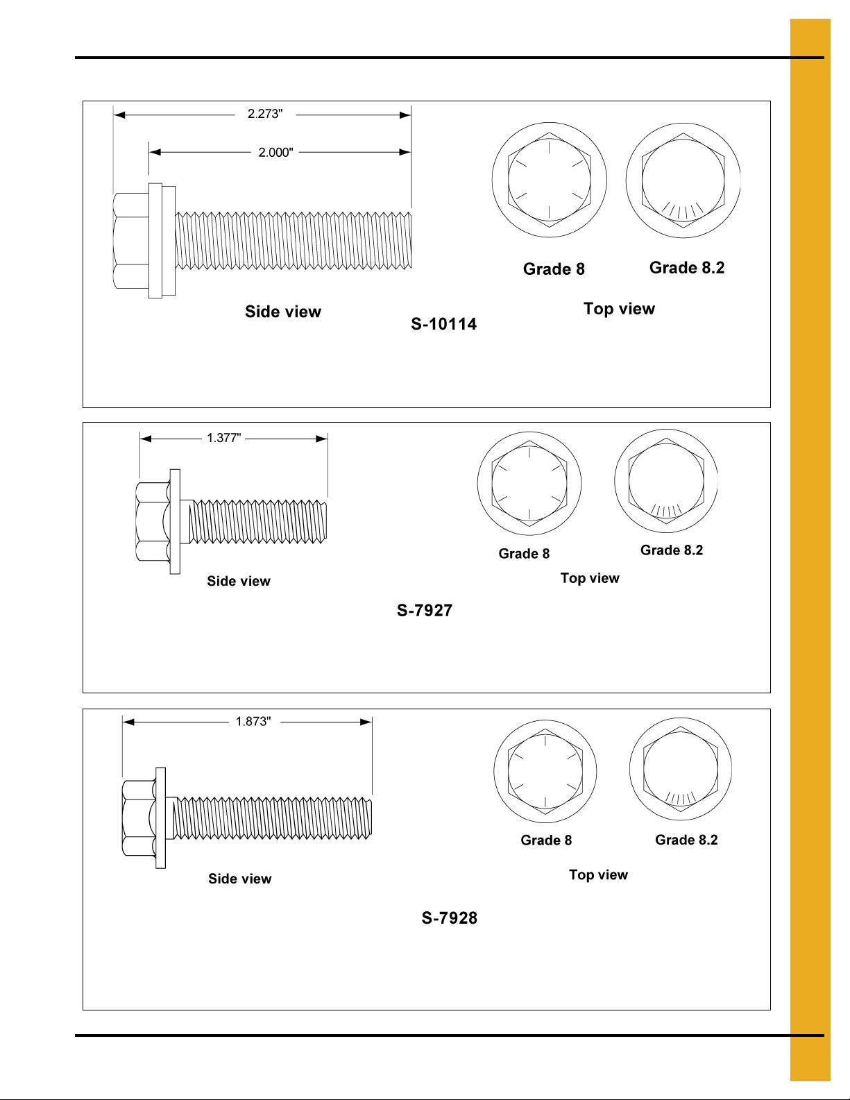
0.4375" x 2.000" Pre-assembled steel backed neoprene washer.
This bolt is used in the horizontal seams of 6 gauge figurate p attern laminated sidewall. The st andard
7/16" nut, S-7332, will be used in conjunction with this bolt.
0.375" x 1.000" Hex flanged head without a plastic sealing washer.
This bolt is used to splice the stiffeners together on the flange s. A flan ge nut is used o n the nut side
of the connection. They are also used on the roof rafter splices for commercial roof systems.
0.375" x 1.500" Hex flanged head without a plastic sealing washer.
This bolt is used to attach the flanges of the 5 gauge base stiffener to the splice plates and splice
laminated stiffeners together. A flange nut is used on the nut side of the connection.
Refer to 2.66" commercial tank bolting requirements for complete bolt usage. (Continued)
PNEG-1859 2.66" Corrugation 135' Diameter Tank with 50 PSF Snow Roof 23
Page 24
5. Bolting Requirements
This 7/16" nut is to be installed at all locations where the 7/16" x 2-1/2" bin bolt S-9444 is installed
(9QL, 8QL and 6FL).
Refer to 2.66" commercial tank bolting requirements for complete bolt usage. (Continued)
NOTE: Outside stiffened bins with sidewall that is 10 gauge laminated or thicker will have three (3) sealing
washers per sheet provided loose. See the instructions for installation of these loose sealing
washers. Outside stiffened bins, 42' and larger diameter also may have loose sealing washers
provided for the roof rafter wall attachment bracket in the roof assembly hardware. All other sealing
washers are pre-assembled onto the bolts. Steel flat washers are shipped loose. Steel flat washers
are utilized in some roof locations.
24 PNEG-1859 2.66" Corrugation 135' Diameter Tank with 50 PSF Snow Roof
Page 25
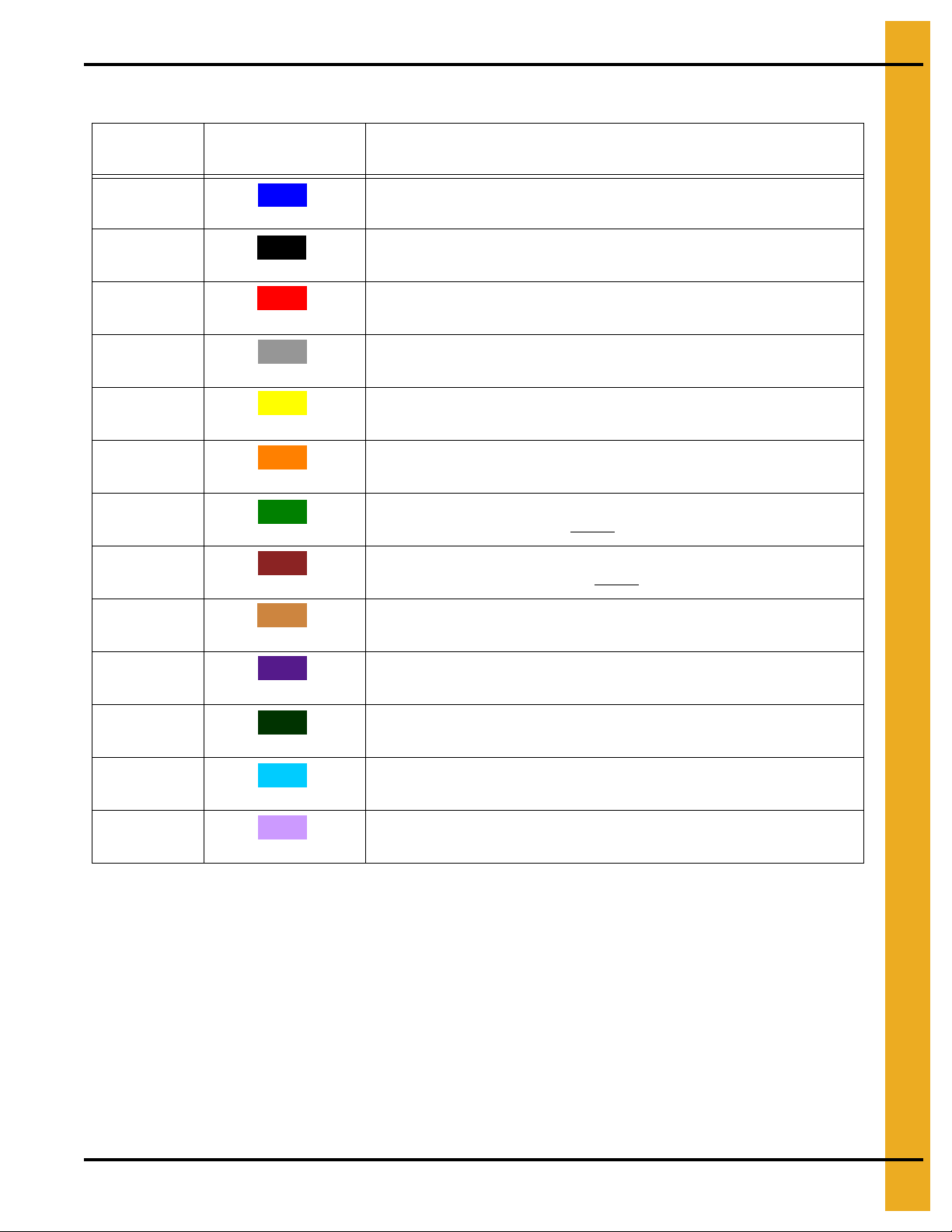
Color Chart for Bin Hardware Bucket Lids
Part # Color Description
5. Bolting Requirements
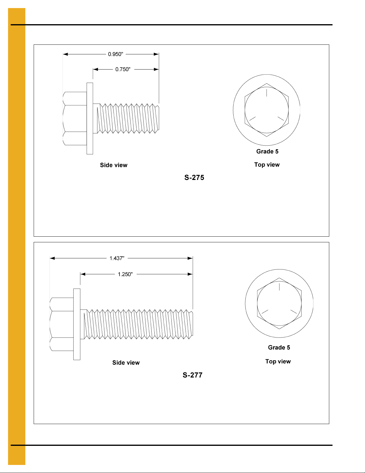
S-275 5/16" x 3/4" Bolt pre-assembled with a steel backed sealing washer
S-277 5/16" x 1-1/4" Bolt pre-assembled with a steel backed sealing washer
S-396 5/16" Hex nut
S-455 3/8" x 1" Bolt pre-assembled with a steel backed sealing washer
S-456 3/8" Hex nut
S-5060 3/8" x 1-1/2" Bolt pre-assembled with a steel backed sealing washer
S-7927 3/8" x 1" Hex flanged head bolt without
S-7928 3/8" x 1-1/2" Hex flanged head bolt without sealing washer
S-8479 7/16" Special recessed nuts
Dark Blue
Black
Red
Grey
Yellow
Orange
Light Green
Dark Brown
Light Brown
sealing washer
S-9373 3/8" Hex flanged nuts
S-9444 7/16" x 2-1/2" Bolt pre-assembled with a steel backed sealing washer
S-9445 3/8" x 2" Bolt pre-assembled with a steel backed sealing washer
S-10114 7/16" x 2" Full thread bolt pre-assembled with a steel backed sealing washer
Dark Purple
Dark Green
Light Blue
Light Purple
PNEG-1859 2.66" Corrugation 135' Diameter Tank with 50 PSF Snow Roof 25
Page 26
6. Caulking Details
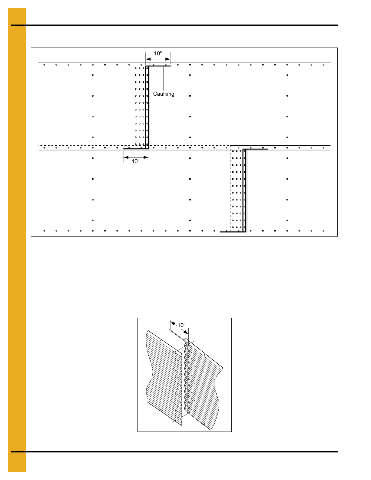
Caulking Detail for Standard (Non-Laminated) Sheets
Figure 6A Standard and Quad Punched Sidewall Sheets as Viewed from Outside
Apply one strip of caulking near the outside edge of the outer sheet and between the outer two (2) rows
of bolts, refer to Figure 6A. A strip of caulking 10" long, should be placed along the horizontal seams.
Before bolting the next ring into place, apply one strip of caulking 10" long on the front of the underlapped
sheet at each joint. Also, a 10" strip of caulking is to be placed along the lower horizontal edge of
lapping sheet at every vertical seam. This will fill the space that occurs betwe en t he ho les ca used by the
overlapping sheets. Use the supplied tube caulk to fill the larger gaps that occur with heavier gauges and
laminated gauges. See Page 27 for details on caulking of laminated sheets.
Figure 6B Caulking Detail as Viewed from Inside of Bin
26 PNEG-1859 2.66" Corrugation 135' Diameter Tank with 50 PSF Snow Roof
Page 27
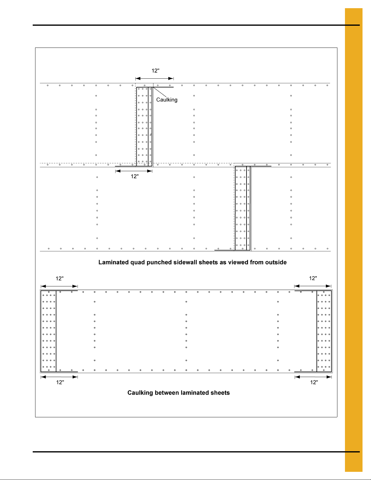
Caulking Detail for Laminated Quad Pattern Sheets
6. Caulking Details
Figure 6C
PNEG-1859 2.66" Corrugation 135' Diameter Tank with 50 PSF Snow Roof 27
Page 28

6. Caulking Details
Caulking Detail for Laminated Figurate Pattern Sheets
Figure 6D
28 PNEG-1859 2.66" Corrugation 135' Diameter Tank with 50 PSF Snow Roof
Page 29

6. Caulking Details
When bolting the two (2) assembled/laminated sheets to each other, apply one strip of caulking near the
outside edge of the outer sheet, between the outer two (2) rows of bolts and o utside the last row of bolts.
(See Figure 6E.) A strip of caulking 12" long should be placed along the horizontal seams. Before bolting
the next ring into place, apply one strip of caulking 12" long on the front of the under lapped sheet at each
joint. Also, a 12" strip of caulking is to be placed along the lower horizontal edge of the lapping sheet at
the vertical seam. This will fill the space that occurs between the holes caused by the overlapping sheets.
Use the supplied tube caulk to fill larger gaps that may occur with thicker gauges.
When assembling two (2) sheets to make a laminated sheet assembly, apply a row of caulk all around the
vertical seam. (See Figure 6E.)
Figure 6E
PNEG-1859 2.66" Corrugation 135' Diameter Tank with 50 PSF Snow Roof 29
Page 30

7. Installation
Base Angle Installation
On the lower edge of the final bottom ring, attach the base angle ring. Before lowering the bin, sealing
provision need to be taken for the entire underneath side of the base angle. (See Figure 7A.) Next, lower
the bin onto the foundation and check for an adequate seal.
Sealing the base of the bin after final construction is done by various methods and materials, based on
materials available, preferences of the customer, etc. However provisions must be made to seal the base
of the bin to prevent moisture from coming into the bin.
Figure 7A
30 PNEG-1859 2.66" Corrugation 135' Diameter Tank with 50 PSF Snow Roof
Page 31

Anchor Bolt Detail
NOTE: Contact GSI engineering for 135' anchor bolt detail.
2.66" Sidewall Gauges
NOTE: Some color codes are different than those used for stiffeners.
Sidewall Gauge Color Code
20 Red
19 Black/Yellow
18 Orange
17 Pink/Light Blue
16 Blue
15 Brown/Red
14 Green
13 Yellow/Blue
7. Installation
12 Black
11 Pink
10 Light Blue
9 Blue/Orange
8 Yellow
6White
5 Fluorescent Green
Laminated Sidewall Color Code
10 Light Blue/Gold
9 Blue/Orange/Gold
8 Yellow/Gold
6 White/Gold
5 Fluorescent Green/Gold
6LF Fluorescent Green/Gold/Ochre
PNEG-1859 2.66" Corrugation 135' Diameter Tank with 50 PSF Snow Roof 31
Page 32

8. 2.66" Commercial Tank Stiffener Instructions (Outside Stiffened)
2.66" Commercial Tank Stiffener Instructions Outside
Stiffened Only
Universal Stiffener and Splice Hardware
Stiffeners Splicing Systems
12 Gauge to 12 Gauge
and Thinner
12 Gauge to 11 Gauge
through 8 Gauge to 5 Gauge, 6 Gauge
5 Gauge, 6 Gauge to 5 Gauge, 6 Gauge
5 Gauge to Laminated, Laminated to Laminated,
Laminated to Laminated Enhanced/Universal
Laminated Enhanced/Universal to Laminated Enhanced/Universal
Laminated Enhanced/Universal to Laminated Enhanced/Enhanced
Laminated Enhanced/Enhanced to
Laminated Enhanced/Enhanced
Use SS-6966 or SS-7427 Splice 2 per Joi nt
Use SS-6966 or SS-7427 Splice 2 per Joi n t
Use SS-6966 or SS-7427 Splice 2 per Joi n t
Splice Hardware Usage (Not Including Sidewall to Splice Bolts)
Stiffeners Splicing Systems Hardware Part # Description Qty
14 Gauge and
15 Gauge
12 Gauge and
13 Gauge
10 Gauge and
11 Ga uge
8 Gauge and
9 Gauge
5 Gauge and 6 Gauge
Laminated
Laminated to
Laminated Enhanced
Laminated Enhanced
Offset Stiffener Joint
Offset Stiffener Joint
SS-7053
Stiff ener Joint
SS-7053
Stiff ener Joint
SS-7053
Stiff ener Joint
SS-6966 or SS-7427
Stiff ener Joint
SS-6966 or SS-7427 and
SS-7398 Stiffener Joint
SS-6966 or SS-7427 and
SS-7398 Stiffener Joint
S-7927 3/8'' x 1'' 8
S-9373 3/8" Flange Nuts 8
S-7927 3/8'' x 1'' 10
S-9373 3/8" Flange Nuts 10
S-7927 3/8'' x 1'' 16
S-9373 3/8" Flange Nuts 16
S-7927 3/8'' x 1'' 20
S-9373 3/8" Flange Nuts 20
S-7928 3/8'' x 1-1/2'' 20
S-9373 3/8" Flange Nuts 20
S-7928 3/8'' x 1-1/2'' 30
S-9373 3/8" Flange Nuts 30
S-7928 3/8'' x 1-1/2'' 38
S-9373 3/8" Flange Nuts 38
S-7928 3/8'' x 1-1/2'' 42
S-9373 3/8" Flange Nuts 42
Offset/Lapped Stiffener
No Separate Splices Plate
Use SS-7053 Splice
Color Code: Yellow
Use SS-7053 Splice
Color Code: Yellow
Use SS-7398 Splice 2 per Joint
Use SS-7398 Splice 4 per Joint
Stiffener to Sidewall Hardware Usage
Splicing Systems Hardware Part # Description
Stiffener to Sidewall
SS-7053
Splice to Sidewall
Laminated Stiffener
to Sidewall
Laminated Enhanced Stiffener
to Sidewall
32 PNEG-1859 2.66" Corrugation 135' Diameter Tank with 50 PSF Snow Roof
S-455 3/8" x 1"
S-456 3/8" Nuts
S-5060 3/8" x 1-1/2"
S-248 3/8" Flat Washer
S-456 3/8" Nuts
S-5060 3/8" x 1-1/2"
S-248 3/8" Flat Washer
S-456 3/8" Nuts
S-5060 3/8" x 1-1/2"
S-248 3/8" Flat Washer
S-456 3/8" Nuts
Page 33

8. 2.66" Commercial Tank Stiffener Instructions (Outside Stiffened)
Commercial Stiffeners for 2.66'' Corrugation
Figure 8A
PNEG-1859 2.66" Corrugation 135' Diameter Tank with 50 PSF Snow Roof 33
Page 34

8. 2.66" Commercial Tank Stiffener Instructions (Outside Stiffened)
Commercial Stiffeners for 2.66'' Corrugation (Continued)
Figure 8B
34 PNEG-1859 2.66" Corrugation 135' Diameter Tank with 50 PSF Snow Roof
Page 35

8. 2.66" Commercial Tank Stiffener Instructions (Outside Stiffened)
2.66'' Corrugation Commercial Stiffeners Splice Details
When installing bottom stiffeners, you may find that in some cases the stiffener with base plate attached
will not rest on the foundation (due to unlevel foundation, etc.). Shim plates have been furnished and
should be used to fill opening between base plate and concrete.
IMPORTANT: If shim plates are not used where required, the downward pressure of the stiffeners will not
be transferred directly to the foundation and bin failure could result.
Stiffener Color Code Chart
Stiffener Gauge Color Code Stiffener Gauge Color Code
15 Red/Orange* 6 White
14 Green/Orange* 5 Fluorescent Green
13 Dark Blue 5+12 Gold/Black
12 Black 5+10 Gold/Light Blue
11 Pink 5+8 Gold/Yellow
10 Light Blue 5+5 Gold/Fluorescent Green
9 Purple 5E+5U Ochre/Gold/White
8Yellow
NOTE: Some colors are different than those used for sidewall sheets.
*NOTE: Only Orange on 1 ring stiffener.
5E+5E Ochre/Gold/White/Brown
Figure 8C
PNEG-1859 2.66" Corrugation 135' Diameter Tank with 50 PSF Snow Roof 35
Page 36

8. 2.66" Commercial Tank Stiffener Instructions (Outside Stiffened)
See Page 32 for usage chart.
Figure 8D
Figure 8E
36 PNEG-1859 2.66" Corrugation 135' Diameter Tank with 50 PSF Snow Roof
Page 37

8. 2.66" Commercial Tank Stiffener Instructions (Outside Stiffened)
See Page 32 for usage chart.
Figure 8F
PNEG-1859 2.66" Corrugation 135' Diameter Tank with 50 PSF Snow Roof 37
Page 38

8. 2.66" Commercial Tank Stiffener Instructions (Outside Stiffened)
Figure 8G
38 PNEG-1859 2.66" Corrugation 135' Diameter Tank with 50 PSF Snow Roof
Page 39

8. 2.66" Commercial Tank Stiffener Instructions (Outside Stiffened)
Figure 8H
PNEG-1859 2.66" Corrugation 135' Diameter Tank with 50 PSF Snow Roof 39
Page 40

8. 2.66" Commercial Tank Stiffener Instructions (Outside Stiffened)
Figure 8I
40 PNEG-1859 2.66" Corrugation 135' Diameter Tank with 50 PSF Snow Roof
Page 41

8. 2.66" Commercial Tank Stiffener Instructions (Outside Stiffened)
Figure 8J
PNEG-1859 2.66" Corrugation 135' Diameter Tank with 50 PSF Snow Roof 41
Page 42

8. 2.66" Commercial Tank Stiffener Instructions (Outside Stiffened)
Non-Laminated Stiffener to Sidewall Det a il
Figure 8K Outside Stiffened Non-Laminated Stiffener to Sidewall Detail
42 PNEG-1859 2.66" Corrugation 135' Diameter Tank with 50 PSF Snow Roof
Page 43

8. 2.66" Commercial Tank Stiffener Instructions (Outside Stiffened)
Laminated Stiffener to Sidewall Detail
Figure 8L Outside Stiffened Laminated Stiffener to Sidewall Detail (11 Gauge laminated only.)
PNEG-1859 2.66" Corrugation 135' Diameter Tank with 50 PSF Snow Roof 43
Page 44

8. 2.66" Commercial Tank Stiffener Instructions (Outside Stiffened)
Laminated Stiffener to Sidewall Detail (Continued)
Figure 8M Outside Stiffened Laminated Stiffener to Sidewall Detail (10 Gauge laminated and thicker only.)
44 PNEG-1859 2.66" Corrugation 135' Diameter Tank with 50 PSF Snow Roof
Page 45

8. 2.66" Commercial Tank Stiffener Instructions (Outside Stiffened)
See bolting requirements
on Page 17.
Special Detail for 10 Gauge and Thicker Laminated Sidewall
PNEG-1859 2.66" Corrugation 135' Diameter Tank with 50 PSF Snow Roof 45
Figure 8N Outside Stiffen ed Laminated Stiffener to Sidewall Detail
(10 Gauge laminated sidewall or thicker only.)
Page 46

8. 2.66" Commercial Tank Stiffener Instructions (Outside Stiffened)
Offset joints and 8 gauge splice plated joints use
3/8" x 1" hex flanged head bolts. All other stiffener joints
use 3/8" x 1-1/2" hex flanged head bolts. Flange nuts
are used on the nut side of all stiffener joint connections.
Detail “B”
(Also refer to laminated
stiffener sections on
Pages 43 and 44.)
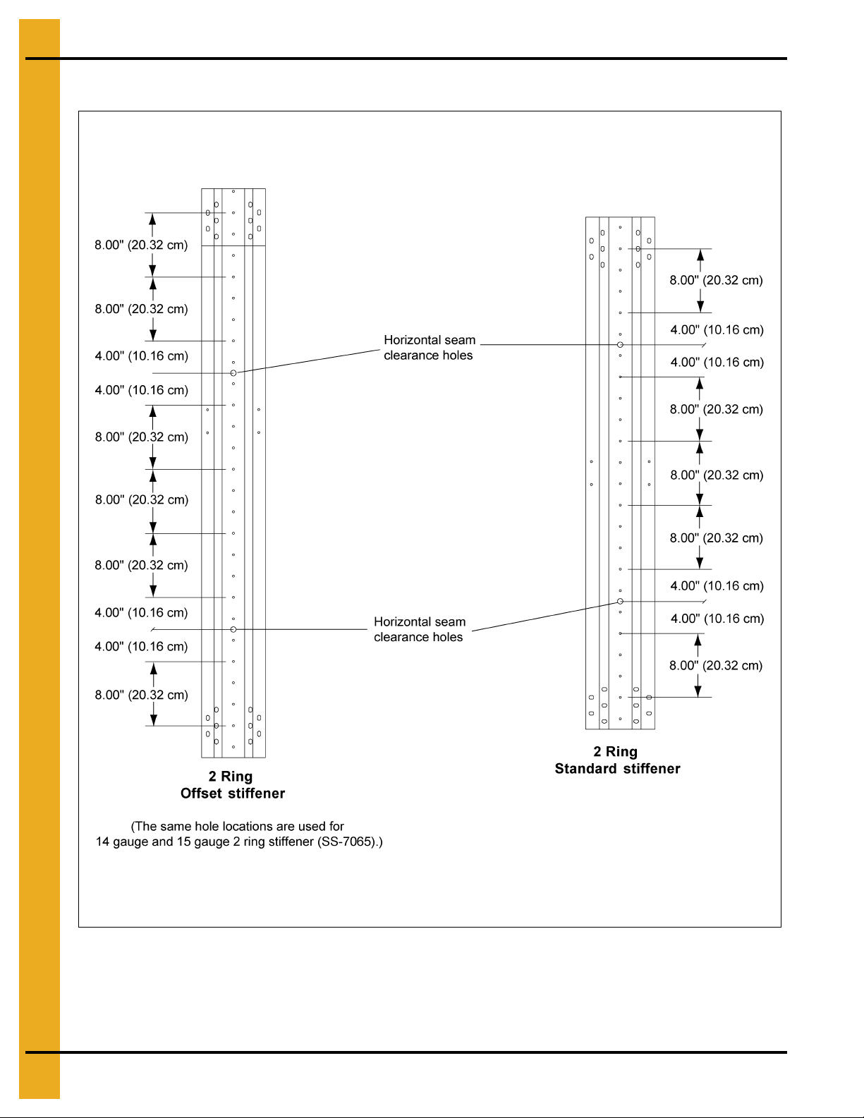
3 Stiffeners per Sidewall Sheet
Commercial Stiffener Starting Location - 2.66'' Reverse Corrugation Outside
Stiffener Only
For sidewall stiffener connections use 3/8" x 1" bin bolt except horizontal seam. Stiffeners will bolt
every 8".
NOTE: Splice plate and laminated stiffener to sidewall connection generally use 3/8" x 1-1/2" bin bolts.
Consult the bolting and hardware requirements section on Page 19 for complete details.
Figure 8O
46 PNEG-1859 2.66" Corrugation 135' Diameter Tank with 50 PSF Snow Roof
Page 47

8. 2.66" Commercial Tank Stiffener Instructions (Outside Stiffened)
Wind rings must be installed in relation to
the ladder rungs as shown here, to ensure
compliance with O.S.H.A. regulations.
Wind Ring Assembly
1. To connect wind ring pipe to the stiffeners, attach with 3/8" x 1" bolts through the flange of the
stiffener. In some cases field drilling of wind ring locations may be required.
2. Attach wind ring pipe section to stiffener using two (2) 3/8" x 6" (S-7248) wind ring clamps.
3. Place pipes end-to-end without overlapping. Fasten together using two (2) wind ring couplers and
six (6) 3/8" x 1" flanged head bolts with flanged nuts. Couplers should be centered on the seam
of pipes.
Figure 8P
Figure 8Q
PNEG-1859 2.66" Corrugation 135' Diameter Tank with 50 PSF Snow Roof 47
Page 48

9. 2.66" Commercial Tank Roof Instructions
Roof Beam Stiffener Sidewall Attachment
Attach the roof beam stiffener (CRP-7150) to the sidewall using 3/8" x 1-1/2" bin bolt (S-5060) and
nut (S-456). Next, field drill four (4) extra holes in the sidewall to match the beam stiffener. Place a
corrugation spacer (S-7041) and a steel backed neoprene washer between the beam stiffener and
sidewall at each hole location (8X total). (See Figure 9A.)
Roof Beam Stiffener and Bracket Attachment
Attach roof beam stiffener (CRP-7150) and bracket (CRP-7151) together in five (5) places using
3/8" x 1" bin bolt (S-455) and nut (S-456). (See Figure 9A.)
Eave Clip Attachment
Attach intermediate eave clip (CRP-5327) and standard eave clip (CRP-5325) with 5/16" x 1-1/4"
bin bolt (S-277) and flange nut (S-3611). (See Figure 9A.)
Figure 9A
48 PNEG-1859 2.66" Corrugation 135' Diameter Tank with 50 PSF Snow Roof
Page 49

9. 2.66" Commercial Tank Roof Instructions
Tension Coupler and Tension Plate Connection
Attach tension plate coupler (CRP-7146) to roof beam stiffener (CRP-7150) and bracket (CRP-7151)
using four (4) 1/2" x 1-1/2" bolts (S-3728) and nut (S-3729).
Attach tension plate (CRP-7149) to tension plate coupler (CRP-7146) using nine (9) 3/4" x 2-3/4" bolts
(S-8387), washers (S-866) and nuts (S-234). Bolt must be inserted from the outside wall of the tank
as shown. Washer must be placed on both bolt and nut side of connection. (See Figure 9B.)
Figure 9B
PNEG-1859 2.66" Corrugation 135' Diameter Tank with 50 PSF Snow Roof 49
Page 50

9. 2.66" Commercial Tank Roof Instructions
Center Collar Placement
With two (2) sidewall rings in place, position the center collar at a height of 39' - 11-7/8" to the bottom of
the center collar as shown in Figure 9C.
Figure 9C
Roof Beam Splice
Splice upper (CRP-7144), middle (CRP-7076) and lower (CRP-7160) roof beams together using
3/4" x 3" bolts (S-8127) and nut (S-234). Note the orientation of the splice plate. The extra 3/8" material
that protrudes below the roof beam flange should match up to its mating beam and be orientated down
after assembly to the center collar and tension plate coupler. NOTE: The top of each roof beam is color
coded with paint and should have a sticker stating “TOP”. (See Figure 9D.)
Figure 9D
50 PNEG-1859 2.66" Corrugation 135' Diameter Tank with 50 PSF Snow Roof
Page 51

9. 2.66" Commercial Tank Roof Instructions
Roof Beam to Tension Coupler and Center Collar
Attach the roof beam to the tension coupler and center collar using 1/2" x 2" bolts (S-8268) and nuts
(S-3729). It is best to set the beams in assembled pairs with all purlins loosely attached. Pairs of beams
should be set by approximately quartering the roof and then evenly filling in between the quarters. The first
sets of beams that should be set are the pairs with X-bracing. See Figure 9J on Page 56 for X-bracing
assembly detail. (See Figure 9E and Figure 9F.)
Figure 9E
Figure 9F
PNEG-1859 2.66" Corrugation 135' Diameter Tank with 50 PSF Snow Roof 51
Page 52

9. 2.66" Commercial Tank Roof Instructions
Notice orientation of “Top” etching
in purlin.
Top
Purlin Attachment to Roof Beams
(Refer to Figure 9H on Page 54 and Figure 9I on Page 55 detail B1-K1.)
Location B1
Attach two (2) purlin clips (CRP-6373) to each side of the beam at purlin location B1 using three (3)
1/2" x 1-1/2" bolt (S-3728) and nut (S-3729). Attach purlin (CRP-6370) to purlin clip (CRP-6373) using
four (4) 3/8" x 1-1/2" bolt (S-7928) and flange nut (S-9373).
Location C1
Attach four (4) purlin clips, two (2) CRP-6383 at the lower set of holes and two (2) CRP-6393 at the
upper set of holes using six (6) 5/8" x 2" bolts (S-4329) and nuts (S-4110). Attach purlin (CRP-6384) to
purlin clips (CRP-6383 and CRP-6393) using six (6) 3/4" x 2-3/4" bolts (S-8387), washers (S-866) and
nuts (S-234). NOTE: Upper purlin clip (CRP-6393) painted ochre. 3/4" x 2-3/4" Bolts (S-8387) must be
used for the C1 clip to purlin connection.
NOTE: Purlin (CRP-6384) is etched with “TOP”. Orientate “TOP” up.
Figure 9G C1 Purlin Orientation
Location D1
Attach two (2) purlin clips (CRP-6373) to each side of the beam at purlin location D1 using three (3)
1/2" x 1-1/2" bolt (S-3728) and nut (S-3729). Attach purlin (CRP-6374) to purlin clip (CRP-6373) using
four (4) 3/8" x 1-1/2" bolt (S-7928) and flange nut (S-9373).
Location E1
Attach two (2) purlin clips (CRP-6373) to each side of the beam at purlin location E1 using three (3)
1/2" x 1-1/2" bolt (S-3728) and nut (S-3729). Attach purlin (CRP-6453) to purlin clip (CRP-6373) using
four (4) 3/8" x 1-1/2" bolt (S-7928) and flange nut (S-9373).
52 PNEG-1859 2.66" Corrugation 135' Diameter Tank with 50 PSF Snow Roof
Page 53

9. 2.66" Commercial Tank Roof Instructions
Purlin Attachment to Roof Beams (Continued)
Location F1
Attach four (4) purlin clips, two (2) (CRP-6383) at the lower side of holes and two (2) (CRP-6393) at the
upper set of holes at purlin location F1 using six (6) 5/8" x 2" bolts (S-4329) and nuts (S-4110). Attach
purlin (CRP-7152) to purlin clip (CRP-6383) and (CRP-6393) using six (6) 3/4" x 2" bolts (S-869) and
nuts (S-234). Also, bolt the roof panel attach (CRP-7153) to the F1 purlin (CRP-7152) using ten (10)
5/16" x 1-1/4" bolts (S-275) and flange nuts (S-3611).
Location G1
Attach two (2) purlin clips (CRP-6373) to each side of the beam at purlin location G1 using three (3)
1/2" x 1-1/2" bolt (S-3728) and nut (S-3729). Attach purlin (CRP-6454) to purlin clip (CRP-6373) using
four (4) 3/8" x 1-1/2" bolt (S-7928) and flange nut (S-9373).
Location H1
Attach four (4) purlin clips two (2) (CRP-7156) at the lower set of holes and two (2) (CRP-6393) at the
upper set of holes at purlin location H1 using six (6) 5/8" x 2" bolts (S-4329) and nuts (S-4110). Attach
purlin (CRP-7154) to purlin clip (CRP-7156) and (CRP-7157) using nine (9) 3/4" x 2" bolts (S-869) and
nuts (S-234). Also, bolt the roof panel attach (CRP-7158) t o the H1 purlin (CRP-7154) using fourteen (14)
5/16" x 1-1/4" bolts (S-275) and flange nuts (S-3611).
Location K1
Attach two (2) purlin clips (CRP-6373) to each side of the beam at purlin location K1 using three (3)
1/2" x 1-1/2" bolt (S-3728) and nut (S-3729). Attach purlin (CRP-7155) to purlin clip (CRP-6373) using
four (4) 3/8" x 1-1/2" bolt (S-7928) and flange nut (S-9373).
Lower Flange Support Bracket
Attach two (2) support pipe brackets (CRP-6450) to the lower side of each middle roof beam using
two (2) 1/2" x 1-1/2" bolts (S-3728) and nuts (S-3729).
PNEG-1859 2.66" Corrugation 135' Diameter Tank with 50 PSF Snow Roof 53
Page 54

9. 2.66" Commercial Tank Roof Instructions
Purlin Attachment to Roof Beams (Continued)
Figure 9H
54 PNEG-1859 2.66" Corrugation 135' Diameter Tank with 50 PSF Snow Roof
Page 55

9. 2.66" Commercial Tank Roof Instructions
Purlin Attachment to Roof Beams (Continued)
Figure 9I
PNEG-1859 2.66" Corrugation 135' Diameter Tank with 50 PSF Snow Roof 55
Page 56

9. 2.66" Commercial Tank Roof Instructions
NOTE: See Figure 9H on Page 54 and Figure 9I on Page 55 for hardware callouts.
X-Bracing Layout
Figure 9J
56 PNEG-1859 2.66" Corrugation 135' Diameter Tank with 50 PSF Snow Roof
Page 57

X-Bracing Layout (Continued)
9. 2.66" Commercial Tank Roof Instructions
Figure 9K
A total of eight (8) X-bracing bays are used for the 135' roof. They should be spaced out as evenly as
possible. Four (4) X-bracing bays should be put up first, quartering the roof. Then place the next four (4)
X-bracing bays between the original four (4) bays. Finally, fill in between all X-bracing bays with sta ndard
pairs keeping an even weight distribution on the center collar. (See Figure 9K.)
Figure 9J on Page 56 shows the X-bracing attaching to the purlin clips. The same hardware is used with
or without the X-bracing. Refer to above instructions for hardware usage. Part numbers and color codes
at each location are detailed in the Chart below.
Part # Description Location Color Code
CRP-6394 CRP-6395 with Turnbuckle B1 Lower Ochre/Red
CRP-6398 X-Bracing Rod Weldment, C1 Upper, 135' Roof C1 Upper Ochre/White
CRP-6401 CRP-6402 with Turnbuckle C1 Lower Ochre/Brown
CRP-6405 X-Bracing Rod Weldment, D1 Upper, 135' Roof D1 Upper Ochre/Black
CRP-6408 CRP-6409 with Turnbuckle D1 Lower Ochre/Purple
CRP-6412 X-Bracing Rod Weldment, E1 Upper, 135' Roof E1 Upper Ochre/Pink
CRP-6413 CRP-6414 with Turnbuckle E1 Lower Ochre/Fluorescent Green
CRP-6417 X-Bracing Rod Weldment, F1 Upper, 135' Roof F1 Upper Ochre/Light Blue
CRP-6420 CRP-6421 with Turnbuckle F1 Lower Ochre/Dark Blue
CRP-6424 X-Bracing Rod Weldment, G1 Upper, 135' Roof G1 Upper Ochre/Yellow
CRP-6426 CRP-6427 with Turnbuckle G1 Lower Ochre/Orange
CRP-6433 CRP-6434 with Turnbuckle H1 Lower Ochre/Blue
CRP-6437 X-Bracing Rod Weldment, K1 Upper, 135' Roof K1 Upper Ochre/Ochre
CRP-6440 CRP-6441 with Turnbuckle K1 Lower Ochre/Grey
CRP-6444 X-Bracing Rod Weldment, Lower Roof Beam, 135' Roof
Lower RB
H1 Upper
Ochre/Gold
PNEG-1859 2.66" Corrugation 135' Diameter Tank with 50 PSF Snow Roof 57
Page 58

9. 2.66" Commercial Tank Roof Instructions
Z-Collar Assembly
Figure 9L
58 PNEG-1859 2.66" Corrugation 135' Diameter Tank with 50 PSF Snow Roof
Page 59

9. 2.66" Commercial Tank Roof Instructions
Z-Collar Assembly (Continued)
(Refer to Figure 9L on Page 58.)
Attach all Z-collars to roof beams using 1/2" x 1-1/2" bolts (S-3728), nuts (S-3729) and washer (S-2121)
on the top only. Leave the bolt loose on the D1 Z-collar (CRP-6344). This bolt will also be used when
placing the roof panel. The part numbers for the Z-collars are as follows:
Location Part # Qty
A1 CRP-6367 5
B1 CRP-6451 15
B2 CRP-7143 15
C1 CRP-6452 15
D1 CRP-6344 15
To splice one Z-collar to the next, use two (2) 1/2" x 1-1/2" bolts (S-3728), nut (S-3729) and washer
(S-2121) on the top and bottom. (See detail splice in Figure 9L on Page 58.)
PNEG-1859 2.66" Corrugation 135' Diameter Tank with 50 PSF Snow Roof 59
Page 60

9. 2.66" Commercial Tank Roof Instructions
See detail in Figure 9N.
Lower Flange Brace Instructions
Refer to Figure 9M and Figure 9N. NOTE: The purlins and Z-collars are hidden for clarity reasons.
The lower flange brace consists of two (2) brace clips (CRP-6450) attached to the bottom of every roof
beam. The brace clips (CRP-6450) are attached using 1/2" x 1-1/2" bolts (S-3728) and 1/2" nut (S-3729).
(See detail - lower flange ring
(CRP-6382) then slides through the support ring clips. There are a total of fifteen (15) support ring pipes
(CRP-6382). Each support ring pipe spans three (3) bays. The pipe should be started halfway between
two (2) roof beams and end in the middle of two (2) roof beams, three (3) bays over. Each pipe should
be tight against the next pipe. The final support pipe placed under the roof beam will have to be cut to fit.
At each splice, wind ring couplers (SWS-4212) should be assembled to h old the pipes together. Wind ring
couplers are assembled using six (6) 3/8" x 1-1/2" flange bolts (S-7928) and flange nut (S-9373).
in Figure 9H on Page 54
for attachment detail.) The support ring pipe
Figure 9M
Figure 9N
60 PNEG-1859 2.66" Corrugation 135' Diameter Tank with 50 PSF Snow Roof
Page 61

Lower Roof Panel Attachment
9. 2.66" Commercial Tank Roof Instructions
Figure 9O
PNEG-1859 2.66" Corrugation 135' Diameter Tank with 50 PSF Snow Roof 61
Page 62

9. 2.66" Commercial Tank Roof Instructions
Lower Roof Panel Attachment (Continued)
(Refer to Figure 9O on Page 61.)
The intermediate roof panel (CRP-6342) and lower roof panel (CRP-6343) will overlap at the G1 purlin
(CRP-6454). Apply two (2) beads of tube caulking at this overlap. The lower roof panel (CRP-6343)
attaches to the eave in four (4) places. Use 5/16" x 1-1/4" bin bolt (S-277) and flange nut (S-3611)
to connect large eave clip (CRP-5325) and intermediate eave clip (CRP-5327) to the sidewall. The
intermediate roof panel (CRP-6342) attaches to the intermediate Z-collar in two (2) places. Use
5/16" x 1-1/4" bolts (S-277), fender washers (S-3671) and flange nuts (S-3611) at this location except
when you must bolt through the roof beam. Use 1/2" x 1-1/2" bolts (S-3728), nuts (S-3729) and washers
(S-2121) at the Z-collar to roof beam attachments. Connect one roof panel rib to the next using
5/16" x 1-1/4" bin bolts (S-277) and flange nuts (S-3611). Flashing (CRP-6380) connects to the top hole
on the intermediate roof panel using the 5/16" x 1-1/4" bin bolt and a #10 self-drilling screw with sealing
washer (S-3929). Each roof panel has to be bolted to the purlins using the 5/16" x 1-1/4" bin bolts
(S-275) and flange nuts (S-3611). The roof panel must be drilled in the flat near the ribs and bolted.
Two (2) bolts are required at each purlin.
NOTE: Install intermediate and lower roof panels at the same time.
62 PNEG-1859 2.66" Corrugation 135' Diameter Tank with 50 PSF Snow Roof
Page 63

Upper Roof Panel Attachment
9. 2.66" Commercial Tank Roof Instructions
Figure 9P
PNEG-1859 2.66" Corrugation 135' Diameter Tank with 50 PSF Snow Roof 63
Page 64

9. 2.66" Commercial Tank Roof Instructions
Upper Roof Panel Attachment (Continued)
(Refer to Figure 9P on Page 63.)
The upper roof panel (CRP-6341) attaches to the intermediate Z-collar (CRP-6344) using 5/16" x 1-1/4"
bolts (S-277) and flange nuts (S-3611). At the rib of the upper panel, a top roof clip (CRP-4829) should be
bolted between the panel and Z-collar. The upper part of the panel attaches to the A1 Z-collar (CRP-6367)
using 5/16" x 1-1/4" bolts (S-277) and flange nuts (S-3611). The upper roof panel (CRP-6341) should be
bolted to the B1, B2 and C1 purlins using two (2) 5/16" x 1-1/4" bin bolt (S-275) and flan ge nu t (S-3611) .
Two (2) holes will have to be drilled through the flat of the roof panels to be bolted to the B1, B2 and C1
Z-collars. The upper roof flashing (CRP-6926) attach to the upper most hole on the roof panel rib using
5/16" x 1-1/4" bolts (S-277) and flange nuts (S-3611). The roof panel flashing (CRP-6926) should also be
screwed to the roof panel using #10 self-drilling screw with sealing washer (S-3929). The center collar
flashing (CRP-6926) will then be sandwiched between the center collar (CRP-6349) and deck plating
(CRP-6353) of the center collar. Use 5/16" x 1-1/2" full threaded carriage bolt (S-6996) and flange nut
(S-3611) to attach the center collar, center collar flashing and deck plating. The center deck plating
(CRP-6354) sits on top of the outer deck plating and also uses 5/16" x 1-1/2" full threaded carriage bolt
(S-6996) and flange nut (S-3611) for attachment. NOTE: The center collar deck plating (CRP-6353
and CRP-6354) will not fit through the center collar from the inside of the bin. Parts must be
brought to the peak from the outside of the bin.
64 PNEG-1859 2.66" Corrugation 135' Diameter Tank with 50 PSF Snow Roof
Page 65

10. 2.66" Commercial Tank Accessories Installation
Roof Vent Assembly
The following instructions are for assembling and installing the wire grill guard roof vent. Before beginning
assembly, check the packing list to ensure all components have been received. The unit is easiest
assembled in the upside down position as shown in Figure 10C on Page 66. Locate the roof vent as
shown in Figure 10G on Page 67.
Figure 10A Roof Panel
Figure 10B Center Collar Caulking Detail
PNEG-1859 2.66" Corrugation 135' Diameter Tank with 50 PSF Snow Roof 65
Page 66

10. 2.66" Commercial Tank Accessories Installation
Assembly
1. Turn one roof vent housing (MIS-6778) upside down. (See Figure 10C.)
2. Insert 5/16" x 1-1/4" bin bolt with neoprene washer through the hole in the side of the roof vent. Place
jamb nut onto the bolt and tighten. (See Figure 10C.)
3. Slide one eyelet of grill guard onto the 5/16" bin bolt.
4. Insert 5/16" x 1-1/4" bin bolt with neoprene washer through the other side of the roof vent, through
jamb nut and other eyelet of grill guard. Tighten nut against vent housing side.
5. Apply a bead of tube caulking around the three (3) housing sides of the roof vent where it meet s the
hold-down angle.
6. Place hold-down angle (MIS-4404) on the assembled roof vent. The wide end of the hold-down angle
must face the vent discharge. Once aligned, screw nine (9) #10 self-drilling screws (S-280) through
the roof housing and into the hold-down angle. (See Figure 10D.)
Figure 10C Figure 10D
66 PNEG-1859 2.66" Corrugation 135' Diameter Tank with 50 PSF Snow Roof
Page 67

10. 2.66" Commercial Tank Accessories Installation
Installation
7. If the roof sheet does not have a pre-punched hole for the roof vent, a hole must be cut. Cut the hole
to match the roof vent. The inside edge of the hole should be approximately 15" from the eave.
(See Figure 10G.)
8. Place the three (3) foam strips on roof sheet, as shown in Figure 10F. Position roof vent over foam
strips and bolt down using 5/16" x 3/4" bin bolts and nuts. NOTE: See Figure 10G for lower two (2)
bolts of vent.
Figure 10E Figure 10F
Figure 10G
PNEG-1859 2.66" Corrugation 135' Diameter Tank with 50 PSF Snow Roof 67
Page 68

10. 2.66" Commercial Tank Accessories Installation
Roof Exhauster Placement
The figure shown is the recommended roof exhauster placement on the 135' bin. A Z-shape reinforcement
piece (CRP-6447) is sent with 135' roofs with exhausters. The reinforcement piece should be placed
roughly 28.00" from the middle of the upper roof beam splice. That dimension is taken from the upper
face of the Z-reinforcement piece. The second from the top hole of the roof exhauster support angle should
be line up with the C1 Z-collar. Two (2) 3/8" diameter holes should be drilled through the roof panel and
into the C1 Z-collar on each side of the exhauster housing. The exhauster should be fast ened with 5/16 "
hardware. Next the Z-reinforcement part should be placed under the lowest hole on the roof exhauster
support angle. The Z-reinforcement (CRP-6447) should be bolted to the roof beam and bolted to the
exhauster support angles. Four (4) holes will need to be drilled through the roof beams, Z-reinforcement
and roof panel to attach with 5/16" hardware. NOTE: Caulking will be needed at any locations of drilling
or cutting of the roof panels. (See Figure 10H.)
Also included is tubing for bracing the roof exhauster housing to the roof panels. Bracing angle and
location is determined by the installer. Care needs to be taken not to interfere with any other equipment
on the roof.
Figure 10H
68 PNEG-1859 2.66" Corrugation 135' Diameter Tank with 50 PSF Snow Roof
Page 69

10. 2.66" Commercial Tank Accessories Installation
Roof Exhauster Placement (Continued)
Figure 10I
PNEG-1859 2.66" Corrugation 135' Diameter Tank with 50 PSF Snow Roof 69
Page 70

10. 2.66" Commercial Tank Accessories Installation
Safety Ring Placement
The safety ring is set up for the bottom hole of the top panel. A total of se venteen (17) pieces of tubing are
shipped for the 135' roof. At the splice between two (2) pieces, insert the 1" - 6 x 6" fully threaded screw
into one piece and run the two (2) nuts halfway onto the all thread screw. Then insert the next piece of
pipe onto the screw. Stake the threads or otherwise secure the nuts ag ainst dislodgin g af ter th e ring h as
been completely installed. (See Figure 10J.)
Figure 10J
70 PNEG-1859 2.66" Corrugation 135' Diameter Tank with 50 PSF Snow Roof
Page 71

10. 2.66" Commercial Tank Accessories Installation
Temperature Cable Layout
Figure 10K shows the GSI recommendation for the 135' commercial bin temperature cable layout, based
on a temperature cable manufacturer’s system. This detail is provided solely for the purpose of facilitating
proper support bracket placement. It is fully the responsibility of the dealer, customer, contractor or
said agent of such parties to confirm details of the system to be used. GSI is not responsible for the
effectiveness or performance of any temperature cable monitoring system or layout.
Note that the roof is designed for cables on a radius of 10', 32' and 55'. A maximum of one temperature
cable should hang from each beam. There are a total of forty five (45) beams which results in a maximum
of forty five (45) temperature cables. The layout shown includes thirty four (34) temperature cables;
four (4) cables are on a 10' radius, fifteen (15) cables on a 32' radius and fifteen (15) cables on a 55'
radius. See chart on Page 72 for tabled layout. Any variation from this pattern or cable quantity
above forty five (45) must be reviewed by GSI. This must be reviewed well in advance of the start of
roof construction.
See Figure 10L on Page 73 for temperature cable bracket installation instructions.
Figure 10K GSI 135' Diameter Temperature Cable Layout
PNEG-1859 2.66" Corrugation 135' Diameter Tank with 50 PSF Snow Roof 71
Page 72

10. 2.66" Commercial Tank Accessories Installation
Temperature Cable Layout (Continued)
Rafter # Cable # Radius Location
1 1 10'
2 5 32'
3 20 55'
4- 5 6 32'
6 21 55'
7 - 8 7 32'
9 22 55'
10 - 11 8 32'
12 23 55'
13 2 10'
14 9 32'
15 24 55'
16 - 17 10 32'
18 25 55'
19 - 20 11 32'
21 26 55'
22 - 23 12 32'
24 27 55'
25 3 10'
26 13 32'
27 28 55'
28 - 29 14 32'
30 29 55'
31 - 32 15 32'
33 30 55'
34 4 10'
35 16 32'
36 31 55'
37 - 38 17 32'
39 32 55'
40 - 41 18 32'
42 33 55'
43 - 44 19 32'
45 34 55'
72 PNEG-1859 2.66" Corrugation 135' Diameter Tank with 50 PSF Snow Roof
Page 73

10. 2.66" Commercial Tank Accessories Installation
NOTES: 1. Do not attach weights to temperature cables,
secure bottom of cables with a light twine to the floor.
2. No roof beam shall support more than one cable.
3. If single center cable exists, consult GSI.
Temperature Cable Bracket (CRP-6205) Assembly
Instructions (Optional)
Figure 10L shows the assembly of the CRP-6205 temperature cable bracket. Note, only one bracket
should be used per roof beam.
PNEG-1859 2.66" Corrugation 135' Diameter Tank with 50 PSF Snow Roof 73
Figure 10L
Page 74

10. 2.66" Commercial Tank Accessories Installation
Inside Ladder Installation
The following are special instructions for assembling inside ladders in 135' diameter commercial bins.
Ladder Standoff Detail
Figure 10M Ladder Standoff Detail (for standard bins)
74 PNEG-1859 2.66" Corrugation 135' Diameter Tank with 50 PSF Snow Roof
Page 75

10. 2.66" Commercial Tank Accessories Installation
Ladder Section Assembly
Two (2) LDR-4317 splice plates are required to attach each ladder section. The head of the bolt should
be to the inside of the ladder with the splice plate on the outside as shown. Use 5/16" x 3/4" bolts for
all connections. (See Figure 10N.)
NOTE: With most installations, the last ladder section installed to reach either the ground or the
intermediate platform will need to be cut to fit.
Figure 10N
PNEG-1859 2.66" Corrugation 135' Diameter Tank with 50 PSF Snow Roof 75
Page 76

10. 2.66" Commercial Tank Accessories Installation
Inside Ladder Placement
The inside ladder package includes the ladder, starter brackets, standoff brackets, reinforcement straps
and ending bracket. Begin by positioning the ladder directly under the manway roof panel and install the
starter bracket as shown in Figure 10O. Place the standoff brackets every horizontal seam or 32" vertically
on the sidewall sheets. A strap is then used from one standoff bracket to the next. Use 5/16" bin bolts to
attach the standoff brackets to the sidewall.
Figure 10O Inside of Grain Bin
The inside ladder package for 135' diameter commercial bins include a strap (LDR-5132) that runs
from one standoff bracket (LDR-4314) to the next. Begin assembling the straps in the second ring of
the sidewall.
Refer to diagram and follow the correct dimensions as shown in Figu re 10P on Page 77. The ladder starter
brackets must be located in line with the horizontal seam. Check the 4' ladder section to make sure the
ladder rung dimples are to the top surface and attach to the starter brackets using the hole located 1"
from the top of the ladder.
76 PNEG-1859 2.66" Corrugation 135' Diameter Tank with 50 PSF Snow Roof
Page 77

10. 2.66" Commercial Tank Accessories Installation
Inside Ladder Placement (Continued)
Figure 10P Outside Stiffened
NOTE: Be sure to push ladder sections up and tighten. Do not tighten ladder section splices with ladder
sections hanging under their own weight.
Now all standoff brackets and straps must be installed every 32" and attached to each 4' section required.
Figure 10Q Un-assembled Reinforcing Strap
PNEG-1859 2.66" Corrugation 135' Diameter Tank with 50 PSF Snow Roof 77
Figure 10R Assembled Reinforcing Strap
Page 78

10. 2.66" Commercial Tank Accessories Installation
Inside Ladder Bottom Bracket
The bottom ladder section may need to be cut off if the length is too long. Cut the b ottom sectio n at least
12" from the bottom of the floor. Attach the bottom inside ladder brackets (LDR-5133) to the last ladder
section using the six (6) holes per ladder rail. You may need to drill out the holes in the last ladder section
with a 3/8" drill bit. You will also need to drill two (2) 3/8" holes through the sidewall to attach each bottom
bracket to the sidewall. Use 5/16" hardware at all attachment points. (See Figure 10S.)
Figure 10S
78 PNEG-1859 2.66" Corrugation 135' Diameter Tank with 50 PSF Snow Roof
Page 79

10. 2.66" Commercial Tank Accessories Installation
135' 2 Ring Door Instructions
IMPORTANT: This GSI commercial 2 ring door is designed for use in the 2.66" corrugation 135' diameter
NCL tank. This door should not be installed in any tank not manufactured by GSI.
Door Placement
The commercial 2 ring door is installed in the bottom 2 rings. The door should normally be placed in line
with the conveyor. The center of the door must be positioned directly below the vertical seam of the ring
above it. The door can not be assembled properly, if the vertical seam is offset to one side of the door.
An intermediate discharge well should be located near the wall to clear grain from the area of the access
door. The two (2) anchor bolts for the door should be drill in anchor bolts placed after asse mbly of
the door. See “sidewall and stiffener door attachment” section on Page 88 for more details on the
anchor bolts.
The door has an inside frame weldment and an external frame weldment/assembly. If the tank has not
been erected, the internal frame weldment should be placed inside the tank before erection. If the tank
has been erected or erection has begun, it will be necessary to remove sidewall and stiffeners in the door
placement area to place the inside frame weldment. A long and short special door sidewall sheets are sent
with the 2 ring door. See Figure 10T for door placement and special sidewall sheet usage.
Figure 10T
PNEG-1859 2.66" Corrugation 135' Diameter Tank with 50 PSF Snow Roof 79
Page 80

10. 2.66" Commercial Tank Accessories Installation
Jamb Plate Assembly
The jamb plates are bolted between the inner and outer door frame weldments (NCWT0246 (outer) and
NCWT0247 (inner)). The left jamb plate (NCWT0265L) has a “L” cut out in the plate. See Figure 10U
for “L” detailed orientation. The jamb plates bolt to the frame weldments using 7/16" x 2-1/2" bin bolts
(S-9444) and special recessed nuts (S-8479). Bolt heads should be orientated to outside of bin.
Figure 10U
80 PNEG-1859 2.66" Corrugation 135' Diameter Tank with 50 PSF Snow Roof
Page 81

10. 2.66" Commercial Tank Accessories Installation
Inner Door Assembly
The inner door hinges (NCWT0254) are bolted to the inner door frame weldment through tapped holes.
(See detail B in Figure 10V.) Attach using 3/8" x 5/8" bolts (S-7185) and washer (S-248).
The 2 ring door requires eight (8) total latch bar holders (WD-6234) assembled to the inner door frame
weldment. Washers will be used to adjust the distance between the frame and the la tch bar holder for the
best fit of the inner doors. Use 1/2" washers (S-2120) and 1/2" x 1-1/2" bolt (S-3728) to secure the latch
bar holders (WD-6234). (See detail A in Figure 10V.)
The 2 ring door requires eight (8) total bearing pins (WD-6224) to be used. Attach the bearing pins to the
inner door weldment using 5/16" x 1-1/2" bolts (S-2741), washer (S-845) and flange nut (S-3611). The
bearing pins should be attached at the eight (8) slots in the inner face of the weldment as shown in
Figure 10V. Leave the bearing pins loose until inner doors have been mounted to ensure a better fit.
Tighten the bearing pins once the inner doors are attached.
Figure 10V
PNEG-1859 2.66" Corrugation 135' Diameter Tank with 50 PSF Snow Roof 81
Page 82

10. 2.66" Commercial Tank Accessories Installation
Inner Door Assembly (Continued)
Figure 10W shows the hinge and handle assembly onto the upper and lower inner doors. Note the hinge
orientation in detail C of Figure 10W. 5/16" x 3/4" Bolts (S-275) and nuts (S-396) are used at most
attachment points. See Figure 10W for 5/16" x 1-1/4" bolt (S-277) and 5/16" x 3/4" truss head bolt
(S-4303) usage. Note usage of latch bushing (WD-6040) where the right hand and left hand latches
(WD-6037 and WD-6038) connect to the reinforcement angle (NCWT0158). The right and left hand
latches should be placed inside the reinforcement angles and attached using 5/16" lock nuts (S-5220).
Figure 10W
82 PNEG-1859 2.66" Corrugation 135' Diameter Tank with 50 PSF Snow Roof
Page 83

10. 2.66" Commercial Tank Accessories Installation
Inner Door Assembly (Continued)
The upper and lower door assemblies can now be assembled to the inner door weldment. Attach the
door assemblies to the hinges using 3/8" x 4-1/2" bolts (S-1443), nuts (S-456) and washers (S-248).
Adjust bearing pins and latch bar holders for best fit and tighten all bolts. (See Figure 10X.)
Figure 10X
PNEG-1859 2.66" Corrugation 135' Diameter Tank with 50 PSF Snow Roof 83
Page 84

10. 2.66" Commercial Tank Accessories Installation
Outer Door Assembly
Attach three (3) reinforcement channels (NCWT0162), two (2) hinges (NCWT0170) and two (2) retaining
brackets (WD-033) to the outer door cover with decals (NCWT0161D). Decals should be orientated
to inside of bin. Apply foam seal strip (S-8610) all along outer cover to seal tank.
bolt usage.
See Figure 10Y
for
Figure 10Y
84 PNEG-1859 2.66" Corrugation 135' Diameter Tank with 50 PSF Snow Roof
Page 85

10. 2.66" Commercial Tank Accessories Installation
Assembled outer cover
(See Figure 10Y on
Page 84.)
Outer Door Assembly (Continued)
Attach outer cover angle (NCWT0168) to the outer door weldment using 5/16" x 1-1/4" bolts (S-277),
nuts (S-396) and washers (S-845) for all connections. Attach hinge weldment (NCWT0165) and latch plate
(NCWT0166) to outer cover angle (NCWT0168). See detail D in Figure 10Z for orientation. The outer
cover then attaches to the hinges with 3/8" x 4-1/2" bolt (S-1443), nuts (S-456) and washers (S-248).
PNEG-1859 2.66" Corrugation 135' Diameter Tank with 50 PSF Snow Roof 85
Figure 10Z
Page 86

10. 2.66" Commercial Tank Accessories Installation
Sidewall and Stiffener Door Attachment
Attach seal weldment (NCWT0258) to the inner and outer door weldments using eight (8) 3/8" x 1"
standard bolt (S-7469), special sealing washer (S-10102) and nut (S-456). (See Figure 10AA.)
Figure 10AA
86 PNEG-1859 2.66" Corrugation 135' Diameter Tank with 50 PSF Snow Roof
Page 87

10. 2.66" Commercial Tank Accessories Installation
Sidewall and Stiffener Door Attachment (Continued)
Attach sidewall to outside of jamb plates. Use 7/16" x 2-1/2" (S-9444) bin bolt and recessed nuts
(S-8479) to attach sidewall to jamb plates. Place corrugated sealing strip (CWT-0053) between outer
and inner edges of the sidewall to jamb plate connection. Caulk around the sealing strip and around the
sidewall to header connection as well. (See Figure 10AB.)
Figure 10AB
NOTE: NCL135-19 and NCL135-20 uses sidewall pattern SS-7412 as the short sheet and SS-7411
as the long sheet. NCL135-21 uses SS-7400 and SS-7401 in the bottom ring and SS-7411
and SS-7412 in the second from bottom ring.
PNEG-1859 2.66" Corrugation 135' Diameter Tank with 50 PSF Snow Roof 87
Page 88

10. 2.66" Commercial Tank Accessories Installation
Sidewall and Stiffener Door Attachment (Continued)
Position 2 ring door stiffener weld (NCWT0218) under base stiffener sitting on top of 2 ring door header.
Attach header, base stiffer and 2 ring door stiffener together with 3/4" x 5" full threaded bolt (S-7324),
anchor bolt washer (HT-635), washer (S-866) and nut (S-234). (See detail F in Figure 10AC.)
After all final adjustments to the door have been made, the anchor bolts should be drilled in place
through the external frame. GSI recommends Hilti 1" x 12" H.A.S. threaded anchor and 1" x 8-1/4" H.V.U.
adhesive capsules (for seismic or special situation tanks, consult GSI engineering).
Figure 10AC
88 PNEG-1859 2.66" Corrugation 135' Diameter Tank with 50 PSF Snow Roof
Page 89

11. Warranty
9101239_1_CR_rev7.DOC (revised July 2009)
GSI Group, LLC Limited Warranty
The GSI Group, LLC (“GSI”) warrants products which it manufactures to be free of defects in materials and workmanship
under normal usage and conditions for a period of 12 months after sale to the original end-user or if a foreign sale,
14 months from arrival at port of discharge, whichever is earlier. The end-user’s sole remedy (and GSI’s only obligation)
is to repair or replace, at GSI’s option and expense, products that in GSI’s judgment, contain a material defect in materials
or workmanship. Expenses incurred by or on behalf of the end-user without prior written authorization from the GSI
Warranty Group shall be the sole responsibility of the end-user.
Warranty Extensions:
The Limited Warranty period is extended for the following products:
Product Warranty Period
Performer Series Direct Drive Fan Motor 3 Years
AP Fans and Flooring
Cumberland
Feeding/Watering
Systems
Grain Systems Grain Bin Structural Design 5 Years
Grain Systems
Farm Fans
Zimmerman
All Fiberglass Housings Lifetime
All Fiberglass Propellers Lifetime
Feeder System Pan Assemblies 5 Years **
Feed Tubes (1-3/4" and 2.00") 10 Years *
Centerless Augers 10 Years *
Watering Nipples 10 Years *
Portable and Tower Dryers 2 Years
Portable and Tower Dryer Frames and
Internal Infrastructure †
5 Years
* Warranty prorated from list price:
0 to 3 years - no cost to end-user
3 to 5 years - end-user pays 25%
5 to 7 years - end-user pays 50%
7 to 10 years - end-user pays 75%
** Warranty prorated from list price:
0 to 3 years - no cost to end-user
3 to 5 years - end-user pays 50%
† Motors, burner components
and moving parts not included.
Portable dryer screens included.
Tower dryer screens not included.
GSI further warrants that the portable and tower dryer frame and basket, excluding all auger and auger drive components,
shall be free from defects in materials for a period of time beginning on the twelfth (12
and continuing until the sixtieth (60
th
) month from the date of purchase (extended warranty period). During the extended
th
) month from the date of purchase
warranty period, GSI will replace the frame or basket components that prove to be defective under normal conditions
of use without charge, excluding the labor, transportation, and/or shipping costs incurred in the performance of this
extended warranty.
Conditions and Limitations:
THERE ARE NO WARRANTIES THAT EXTEND BEYOND THE LIMITED WARRANTY DESCRIPTION SET FORTH
ABOVE. SPECIFICALLY, GSI MAKES NO FURTHER WARRANTY OF ANY KIND, EXPRESS OR IMPLIED,
INCLUDING, WITHOUT LIMITATION, WARRANTIES OF MERCHANTABILITY OR FITNESS FOR A PARTICULAR
PURPOSE OR USE IN CONNECTION WITH: (I) PRODUCT MANUFACTURED OR SOLD BY GSI OR (II) ANY ADVICE,
INSTRUCTION, RECOMMENDATION OR SUGGESTION PROVIDED BY AN AGENT, REPRESENTA TIVE OR
EMPLOYEE OF GSI REGARDING OR RELATED TO THE CONFIGURATION, INSTALLATION, LAYOUT, SUITABILITY
FOR A PARTICULAR PURPOSE, OR DESIGN OF SUCH PRODUCTS.
GSI shall not be liable for any direct, indirect, incidental or consequential damages, including, without limitation, loss of
anticipated profits or benefits. The sole and exclusive remedy is set forth in the Limited Warranty, which shall not exceed
the amount paid for the product purchased. This warranty is not transferable and applies only to the original end-user. GSI
shall have no obligation or responsibility for any representations or warranties made by or on behalf of any dealer, agent
or distributor.
GSI assumes no responsibility for claims resulting from construction defects or unauthorized modifications to products
which it manufactured. Modifications to products not specifically delineated in the manual accompanying the equipment at
initial sale will void the Limited Warranty.
This Limited Warranty shall not extend to products or parts which have been damaged by negligent use, misuse, alteration,
accident or which have been improperly/inadequately maintained. This Limited Warranty extends solely to products
manufactured by GSI.
Prior to installation, the end-user has the responsibility to comply with federal, state and local codes which apply to the
location and installation of products manufactured or sold by GSI.
PNEG-1859 2.66" Corrugation 135' Diameter Tank with 50 PSF Snow Roof 89
Page 90

This equipment shall be installed in accordance with
the current installation codes and applicable
regulations, which should be carefully followed in all
cases. Authorities having jurisdiction should be
consulted before installations are made.
Copyright © 2012 by GSI Group
Printed in the USA
GSI Group
1004 E. Illinois St.
Assumption, IL 62510-0020
Phone: 1-217-226-4421
Fax: 1-217-226-4420
www.gsiag.com
CN-300708
 Loading...