

Page 1

Instructions
PNEG-1856
1004 East Illinois Street • Assumption, IL 62510 • 1-217-226-4421
Baldor Motor Kit
Programming Baldor H2 and VS Drives on Dryers Built 1993 and
Prior or 1998 and UP
For the purpose of making Baldor AC drives work with Zimmerman control panels some parameter
settings must be changed. Some parameters remain unchanged. When programming AC drive you must
change only parameters shown in chart on Page 2 and skip those not shown.
Setting Procedure
1. Power up drive.
2. Press MENU key to display programming options.
3. Scroll, with up and down arrow keys, to programming and press ENTER key.
4. Scroll through top level programming menu using up and down arrow keys until setting to be
changed, determined by chart on Page 2, is reached.
5. Press ENTER key to program top level parameters. (Example: Level 1 blocks.)
st
6. Scroll through 1
be modified according to chart on Page 2.
7. Press ENTER at selected 1
level parameter group, using up and down arrow keys, finding the parameters to
st
level parameters to get to individual parameters.
8. Scroll through individual parameters, using up and down arrow keys, finding the parameters to be
modified according to chart on Page 2.
9. Modify factory settings of the individual parameters shown in the chart on Page 2. To do so:
a. Press ENTER key to begin value change.
b. If number, use left and/or right arrow keys to place the blinking cursor over the digit(s) to
be modified.
c. Use up and down arrow keys to change value.
d. Press ENTER to save change.
10. When done scroll to next parameter to be changed (refer to chart on Page 2) by using up and down
arrow keys. Press R to return to the previous screen or S to return to status screen.
11. Repeat process until all parameters shown on chart on Page 2 are programmed.
12. To end programming press R repeatedly until reaching main menu then press Enter at status. This
will bring you back to monitoring at main screen.
Date: 03-19-12 PNEG-1856
Printed in the U.S.A.
Copyright © 2012 by GSI Group
www.gsiag.com
Page 1 of 9
CN-206548
Page 2
Baldor Motor Kit
Programming Baldor H2 and VS Drives on Dryers Built 1993 and
Prior or 1998 and UP (Continued)
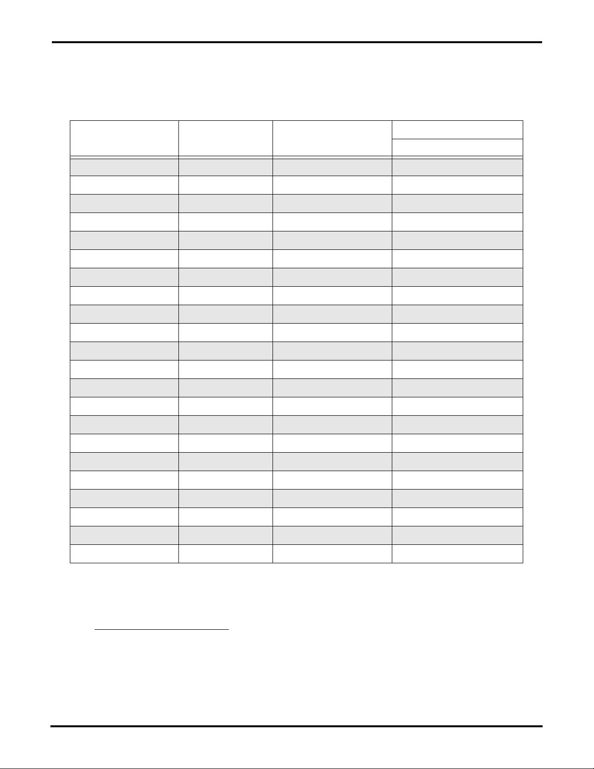
All parameters and their settings to be changed for Zimmerman purposes shown in chart below.
Top Le ve l
Programming Menu
Level 1 Blocks Ramp Rates Accel Time #1 3 Seconds
Level 1 Blocks Keypad Setup Stop Key OFF
Level 1 Blocks Input Setup Operating Mode Standard Run 3 Wire
Level 1 Blocks Output Setup Analog Out 1 Type 0-5V
st
Level
1
Parameter Group
Individual
Parameters
Decel Time #1 3 Seconds
Stop Mode Coast
Run Forward OFF
Run Reverse OFF
Command Source Analog In1
Analog In1 Type Potentiometer
Settings
Zimmerman Changes
Level 2 Blocks Drive Limits Minimum Output Speed 7 Hertz
Maximum Output Speed 75 Hertz
Level 2 Blocks Drive Protect External Trip ON
Level 2 Blocks Motor Data Motor Rated Amps Factory/5 Amps or 6 Amps*
Press R to Exit Press R to Exit Press R to Exit
Press ENTER at Status
NOTE: After programming is complete if local is displayed in upper right hand corner of status screen.
Then Local/Remote button will have to be pressed to change to remote. This is a one time
operation and will not have to be done in the future.
* NOTE: Accutrol Unload Dryers Only
- 5 amps is selected for 17' diameter dryers, 6 amps for
23'-4" diameter dryers. Dryers with metering augers stay at factory setting.
Page 2 of 9 PNEG-1856
Page 3

Baldor Motor Kit
Programming Baldor H2 and VS Drives on Dryers Built 1994-1997
For the purpose of making Baldor AC drives work with Zimmerman control panels some parameter
settings must be changed. Some parameters remain unchanged. When programming AC drive you must
change only parameters shown in chart on Page 4 and skip those not shown.
Setting Procedure
1. Power up drive.
2. Press MENU key to display programming options.
3. Scroll, with up and down arrow keys, to programming and press ENTER key.
4. Scroll through top level programming menu using up and down arrow keys until setting to be
changed, determined by chart on Page 4, is reached.
5. Press ENTER key to program top level parameters. (Example: Level 1 blocks.)
st
6. Scroll through 1
be modified according to chart on Page 4.
7. Press ENTER at selected 1
level parameter group, using up and down arrow keys, finding the parameters to
st
level parameters to get to individual parameters.
8. Scroll through individual parameters, using up and down arrow keys, finding the parameters to be
modified according to chart on Page 4.
9. Modify factory settings of the individual parameters shown in the chart on Page 4. To do so:
a. Press ENTER key to begin value change.
b. If number, use left and/or right arrow keys to place the blinking cursor over the digit(s) to
be modified.
c. Use up and down arrow keys to change value.
d. Press ENTER to save change.
10. When done scroll to next parameter to be changed (refer to chart on Page 4) by using up and down
arrow keys. Press R to return to the previous screen or S to return to status screen.
11. Repeat process until all parameters shown on chart on Page 4 are programmed.
12. To end programming press R repeatedly until reaching main menu then press Enter at status. This
will bring you back to monitoring at main screen.
PNEG-1856 Page 3 of 9
Page 4

Baldor Motor Kit
Programming Baldor H2 and VS Drives on Dryers Built
1994-1997 (Continued)
All parameters and their settings to be changed for Zimmerman purposes shown in chart below.
Top Le ve l
Programming Menu
Level 1 Blocks Ramp Rates Accel Time #1 3 Seconds
Level 1 Blocks Keypad Setup Stop Key OFF
Level 1 Blocks Input Setup Operating Mode Standard Run 3 Wire
Level 1 Blocks Output Setup Analog Out 1 Type 0-5V
st
1
Level
Parameter Group
Individual
Parameters
Decel Time #1 3 Seconds
Stop Mode Coast
Run Forward OFF
Run Reverse OFF
Command Source Analog In2
Analog In2 Type 0-5V
Settings
Zimmerman Changes
Level 2 Blocks Drive Limits Minimum Output Speed 7 Hertz
Maximum Output Speed 75 Hertz
Level 2 Blocks Drive Protect External Trip ON
Level 2 Blocks Motor Data Motor Rated Amps Factory/5 Amps or 6 Amps*
Press R to Exit Press R to Exit Press R to Exit
Press ENTER at Status
NOTE: After programming is complete if local is displayed in upper right hand corner of status screen.
Then Local/Remote button will have to be pressed to change to remote. This is a one time
operation and will not have to be done in the future.
* NOTE: Accutrol Unload Dryers Only
- 5 amps is selected for 17' diameter dryers, 6 amps for
23'-4" diameter dryers. Dryers with metering augers stay at factory setting.
Page 4 of 9 PNEG-1856
Page 5

Baldor H2 and VS Inverter Wiring 1993 and Prior
Baldor Motor Kit
Figure 1
PNEG-1856 Page 5 of 9
Page 6

Baldor Motor Kit
Baldor H2 and VS 1994 and 1995 Panel PLC
Figure 2
Page 6 of 9 PNEG-1856
Page 7

Baldor H2 and VS 1994 and 1995 Panel Relay
Baldor Motor Kit
Figure 3
PNEG-1856 Page 7 of 9
Page 8

Baldor Motor Kit
Baldor H2 and VS 1996 Panel PLC
Figure 4
Page 8 of 9 PNEG-1856
Page 9

Baldor H2 and VS 1997 Panel PLC
Baldor Motor Kit
Figure 5
PNEG-1856 Page 9 of 9
 Loading...