

Page 1
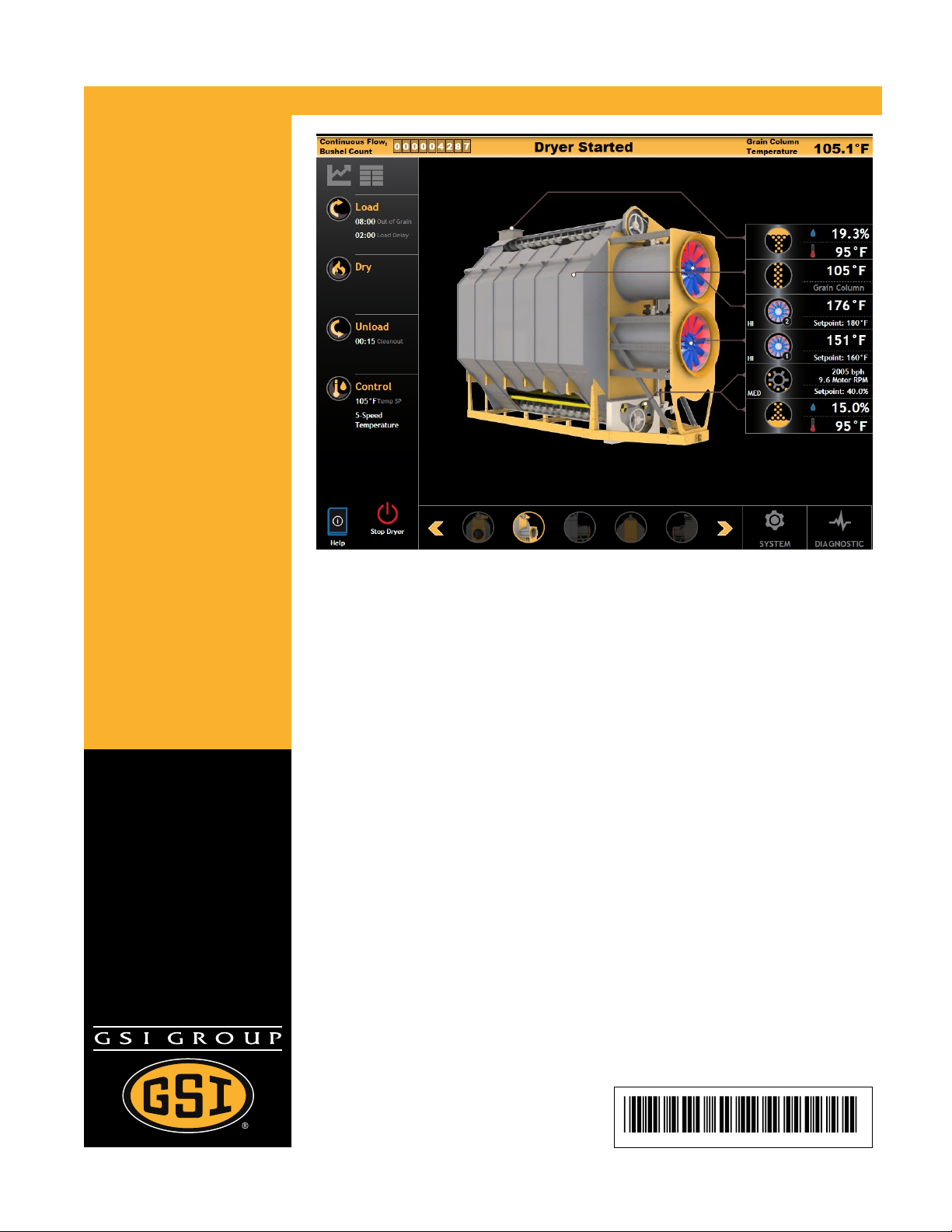
Vision N2 Controller
Models:
PORTABLE DRYERS
User Guide
PNEG-1851
Version 1.0
Date: 11-06-12
PNEG-1851
Page 2

All information, illustrations, photos, and specifications in this manual are based on the latest
information available at the time of publication. The right is reserved to make changes at any
time without notice.
2 PNEG-1851 Vision N2
Page 3

Table of Contents
Contents
About This Guide......................................................................................................................... v
Chapter 1 Safety Precautions ....................................................................................................................7
Safety Guidelines for Portable Dryers............................................................................................7
Cautionary Symbols ....................................................................................................................9
Safety Decals for Portable Dryers ...............................................................................................10
Chapter 2 The Portable Dryer...................................................................................................................13
Overview of the Portable Dryer ................................................................................................... 13
Dryer Configurations..................................................................................................................15
The Control Panel .....................................................................................................................16
Overview of the User Interface.................................................................................................... 19
A Look at Parameter Fields ........................................................................................................23
Entering Parameter Values with the Keypad ................................................................................24
Chapter 3 Getting Started ........................................................................................................................ 27
Powering On the Dryer...............................................................................................................27
Configuring User Preferences.....................................................................................................28
Configuring Your Dryer’s Hardware ............................................................................................. 29
Setting the Dryer’s Timers and Delays......................................................................................... 30
Drying Grain in the Initial Run .....................................................................................................32
Unloading Grain in the Initial Run ................................................................................................33
Chapter 4 Basic Operations ..................................................................................................................... 35
Setting the Plenum Temperature Range ......................................................................................35
Resetting the Dry Grain Counters ...............................................................................................36
Shutting Off the Dryer at the End of the Day.................................................................................36
Shutting Off the Dryer at the End of the Drying Season .................................................................37
Monitoring Grain and Dryer Data in Real Time ............................................................................. 38
Downloading Dryer Data to a USB Flash Drive.............................................................................38
Chapter 5 The Drying Modes....................................................................................................................41
Continuous Flow Mode .............................................................................................................. 41
Continuous Flow Based on Grain Temperature ............................................................................42
Continuous Flow Based on Grain Moisture .................................................................................. 45
Staged Batch Mode ...................................................................................................................46
Staged Batch Based on Drying Time ...........................................................................................47
Staged Batch Based on Grain Temperature.................................................................................49
Staged Batch Based on Drying Time and Grain Temperature ........................................................51
Selecting a Drying Mode ............................................................................................................ 52
Chapter 6 The Wet Grain.......................................................................................................................... 53
The Loading Process ................................................................................................................. 53
Ensuring Dryer Shutdowns When Supply Is Out of Grain .............................................................. 54
Minimizing Load Auger Startups .................................................................................................55
Validating Incoming Moisture and Temperature Readings ............................................................. 56
Chapter 7 The Continuous Flow Drying Process......................................................................................57
Drying Grain in Continuous Flow.................................................................................................57
Setting the 1-Speed Temperature Scheme in Continuous Flow......................................................58
Setting the 2-Speed Temperature Scheme in Continuous Flow......................................................59
Setting the 5-Speed Temperature Scheme in Continuous Flow......................................................60
Setting the 5-Speed Moisture Scheme in Continuous Flow............................................................ 61
Chapter 8 The Staged Batch Drying Process ...........................................................................................63
Drying Grain in Staged Batch .....................................................................................................63
Setting the Time Scheme in Staged Batch ................................................................................... 64
Setting the Temperature Scheme in Staged Batch ........................................................................65
Setting the Time and Temperature Scheme in Staged Batch .........................................................66
Setting the Dual-Setpoint Time Scheme in Staged Batch ..............................................................67
PNEG-1851 Vision N2 3
Page 4

Table of Contents
Setting the Dual-Setpoint Temperature Scheme in Staged Batch ................................................... 68
Chapter 9 The Dry Grain .......................................................................................................................... 71
Validating Outgoing Moisture And Temperature Readings ............................................................. 71
Cleaning the Dry Sensor ............................................................................................................ 72
Setting the Value Range for the Unload Speed.............................................................................73
Adjusting Unload Speeds in Real Time........................................................................................ 73
Ensuring Accurate Unload Speed Rates......................................................................................74
Appendix A Grain Drying Operations..........................................................................................................77
Drying Grain: A Quick Startup Procedure..................................................................................... 77
Initial Settings for Full-Heat and Dry and Cool .............................................................................. 78
The Burner Modes.....................................................................................................................79
Grain Drying: Full-Heat or Dry and Cool.......................................................................................80
A Glance at Cooling Processes ............................................................................................82
Appendix B Grain Drying Graphs................................................................................................................85
Temperature and Moisture Schemes in Continuous Flow ..............................................................86
Temperature Control Schemes in Staged Batch ........................................................................... 87
Time Control Schemes in Staged Batch.......................................................................................92
Appendix C Messages ................................................................................................................................ 97
The Status Messages ................................................................................................................97
Appendix D List of Parameters ................................................................................................................... 99
Vision N2 Parameters for Portable Dryers.................................................................................... 99
Glossary................................................................................................................................ 107
Index ..................................................................................................................................... 111
GSI Group, LLC Limited Warranty.......................................................................................... 115
4 PNEG-1851 Vision N2
Page 5

About This Guide
This guide contains information on operating portable dryers that are equipped with the Vision N2 Network
Dryer Control. It is intended for operators and service technicians, and can be used by both novice and
experienced users of GSI’s portable dryers.
How This Guide Works
The Vision N2 User Guide contains procedures, examples, references, and conceptual information. It also
includes a comprehensive table of contents and index, thus allowing you, the user, to navigate the document with greater ease and efficiency. This guide also contains a glossary of commonly used terms in the
grain drying environment.
Furthermore, an intuitive web version of this guide can be easily accessed via your Vision N2 controller.
Simply click on the Help icon located at the bottom left corner of your screen to access the web version.
The web version can also be accessed off-site via GSI’s remote web application. In addition, your user
interface contains information icons that are located next to parameter fields. Simply click on a parameter’s
information icon for a timely and concise description of that parameter.
Typographical Conventions
Typographical conventions are visual indicators for specific elements of text. These conventions are used
throughout this guide to indicate specific dryer functions and parameters, notes and warnings, or simply for
textual effect.
The following typographical conventions are used throughout this guide:
• Menus that are displayed in the following manner indicate the click sequence that is required to
access the desired menu or parameter:
System→Preferences→Language
• Text that is displayed in bold typeface indicates a button or switch on the dryer’s control panel, or
denotes a parameter in the Vision N2 user interface.
From the submenu pane, click Time and Date.
On the control panel, turn the Power switch to On.
• Text that is Italicized denotes a hyperlink.
For information on how to use the keypad, see Entering Parameter
Values with the Keypad, page 24.
In the PDF and web versions, hyperlinks are blue. Italics are also used to emphasize the italicized
word.
v
Page 6
Vision N2 Controller
Notes and Notices
The following notes and notices are used throughout this guide:
NOTE: Used to denote supplemental information that is directly related to the text that immediately pre-
cedes or follows it.
Tip
Used to provide advice on a particular subject.
Used to describe a real-life scenario that applies to the information that
precedes it. Examples can be displayed in contextual information to help
explain a concept, after an instructional step in a procedure, or following a
task (Task Example).
IMPORTANT: Used to alert you about a situation with potentially unfavorable consequences.
Used to call attention to a potentially hazardous situation which, if not avoided, might
CAUTION
result in minor, moderate, or serious injury.
DANGER
Used to alert you about an extremely hazardous or potentially lethal situation.
vi
Page 7

1 Safety Precautions
Topics Covered in this Chapter
▪ Safety Guidelines for Portable Dryers
▪ Cautionary Symbols
▪ Safety Decals for Portable Dryers
Safety Guidelines for Portable Dryers
Safety guidelines are general-to-specific rules that promote safe practices in the grain drying environment
and which must be respected at all times. Save these safety guidelines for future reference.
Make sure to read these safety guidelines carefully prior to installing, operating, or
CAUTION
Operation
• Read and fully understand this user guide before attempting to operate the grain dryer.
servicing your grain dryer.
• Never operate the grain dryer with its safety guards removed.
• Never operate the grain dryer by bypassing any safety device.
• Never exceed the maximum recommended drying temperature.
• Do not operate the grain dryer in an area where combustible material might be drawn into the fan.
• The operating and safety recommendations in this guide pertain to common cereal grains, as indicated. When drying other types of grain or products, contact the GSI Group, LLC for additional
recommendations.
Servicing
• The power supply must be disconnected when servicing electrical components. Always use extreme
caution when measuring voltage or performing procedures that require the dryer to be turned on.
• Before attempting to remove and reinstall a fan’s propeller, make sure to read the recommended procedure. If you are unsure about performing this procedure or cannot locate it, contact the GSI Group,
LLC before proceeding.
Pre-Season Mode
• When using a controller with Vision N2 software, the pre-season mode allows the fans and heaters to
operate under normal conditions, without the dryer being completely full of grain. In normal mode, the
dryer generates a Loss of Airflow shutdown if you operate the fans without having the dryer full of
grain.
• Following an extended period of inactivity—typically, at the beginning of the drying season, use preseason mode to fully test the dryer.
PNEG-1851 Vision N2
7
Page 8
Chapter 1: Safety Precautions
• To enable pre-season mode, click System→Control (Advanced)→Board Mode and then select
Pre-season Mode.
• Place the dryer in normal mode once inspections have been completed and you are ready to dry
grain.
IMPORTANT: If you power off the dryer while in pre-season mode, normal mode is automatically
enabled the next time you power on the dryer. Make sure to reselect pre-season
mode if further tests are required.
Cleanliness
• Keep the grain dryer clean at all times.
• Do not allow fine material to accumulate in the plenum chamber.
• An unclean plenum increases resistance to airflow, increases drying time, reduces drying efficiency,
and creates a fire hazard.
• Always keep the area around the fan’s air inlet clear of any obstacles and combustible material.
Augers/Auxiliary Conveyors
Always use extreme caution when working around augers and auxiliary conveyors
CAUTION
because they can start automatically.
• Always keep auger drive belts adequately tensioned to prevent slippage.
• Make sure that the technical specifications and capacities of the auxiliary conveyors are matched to
those of the dryer augers.
Burners/Gas Lines
• Regularly check for leaks at all gas line connections. If any leaks are detected, do not operate the
grain dryer. Shut off the main power and repair the leaks before operating. Gas lines must be
replaced regularly as required by the local gas regulations for your area.
• Routinely check for potential gas plumbing leaks. Check the liquid propane vaporizer for contact with
the burner vanes.
• Never use an open flame to locate gas leaks. Pour a solution of soap and water over the gas pipe
joints and connections, and check for the appearance of small bubbles.
• Set the pressure regulator to avoid applying excessive gas pressure to the burner during ignition or
when the burner is on.
• Do not use flammable or combustible materials in the dryer’s vicinity because explosive vapors can
be drawn into the fan and ignite.
• Always use extreme caution when working around high-speed fans and gas burners because they
can start automatically.
8 PNEG-1851 Vision N2
Page 9
Chapter 1: Safety Precautions
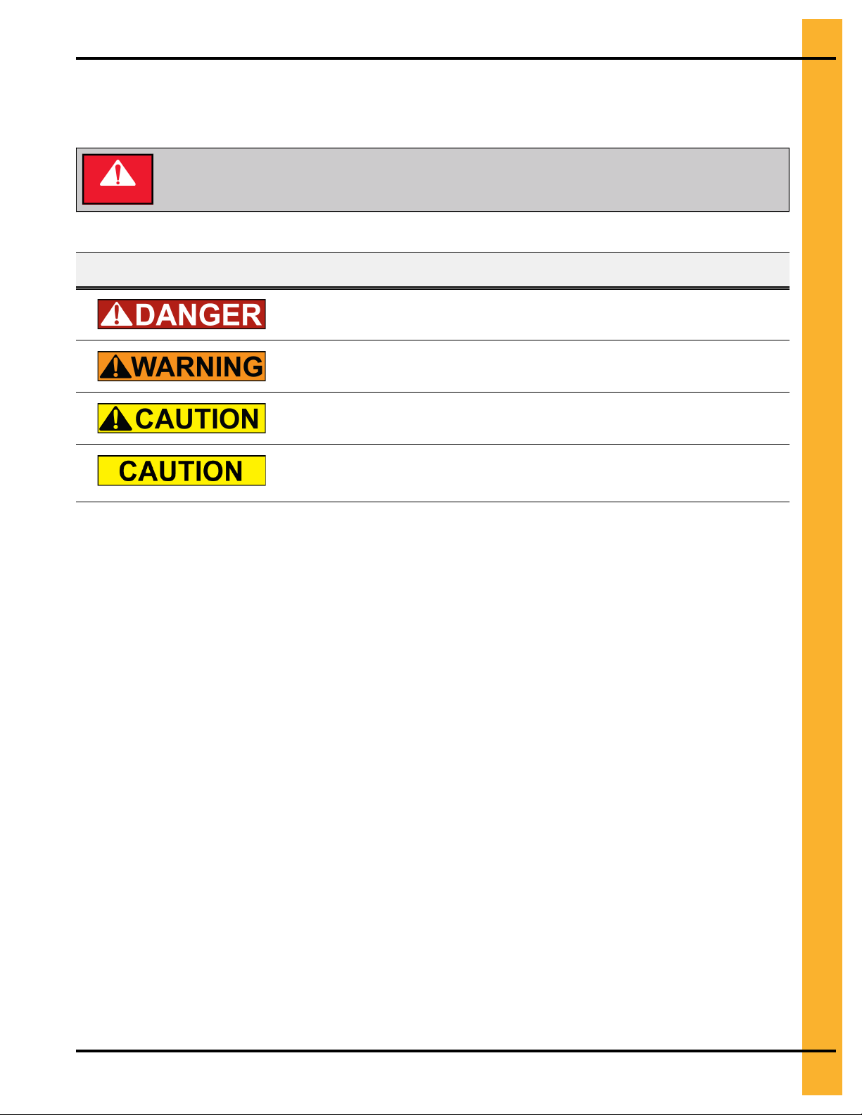
Cautionary Symbols
Cautionary symbols are present in the various decals of your equipment and alert you to the possible or
imminent risk of danger.
Make sure to familiarize yourself with the cautionary symbols prior to installing,
DANGER
Table 1-1 Overview of the different cautionary symbols
operating, or servicing your equipment. Failure to do so might lead to serious injury
or death.
Symbol Description
This symbol indicates an imminently hazardous situation which, if not avoided,
will result in serious injury or death.
This symbol indicates a potentially hazardous situation which, if not avoided,
might result in serious injury or death.
This symbol indicates a potentially hazardous situation which, if not avoided,
might result in minor or moderate injury.
This symbol indicates a potentially hazardous situation which, if not avoided,
might result in property damage.
PNEG-1851 Vision N2 9
Page 10
Chapter 1: Safety Precautions
Safety Decals for Portable Dryers
The safety decals on your grain dryer are safety indicators which must be carefully read and understood
by all personnel involved in the installation, operation, service, and maintenance of the grain dryer.
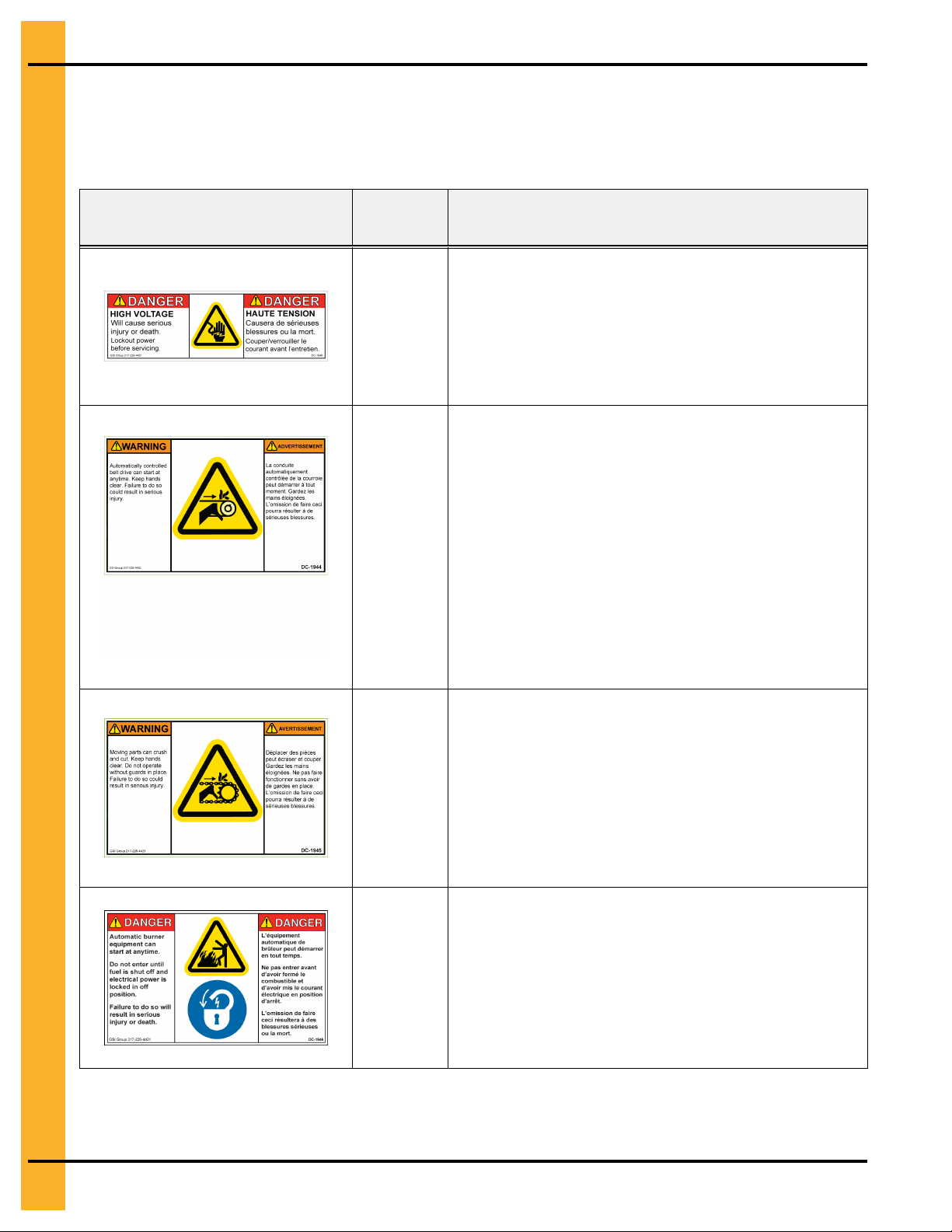
Table 1-2 Description of the grain dryer’s decals
Decal Decal No. Location
This decal appears:
• On the lid of the fan/heater control box
DC-1948
• On the front of the fan/heater control box
• Inside the dryer’s upper control box
This decal appears:
• On the bottom auger belt guard
DC-1944
DC-1945
• On the front bearing plate (visible when the bottom
auger belt guard is removed)
• At the rear of the dryer (for dryers equipped with the
front discharge option)
• On the top auger belt guard
• On the inside belt guard body (visible when the top
auger belt guard is removed)
This decal appears:
• On the bottom auger belt guard
• On the front bearing plate (visible when the bottom
auger belt guard is removed)
• At the rear of the dryer (for dryers equipped with the
front discharge option)
This decal appears:
• On the inside of the rear plenum access door
DC-1946
10 PNEG-1851 Vision N2
• On the outside of the rear plenum access door
Page 11
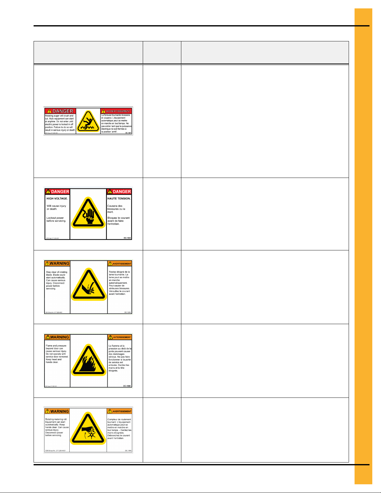
Table 1-2 Description of the grain dryer’s decals (cont'd.)
Decal Decal No. Location
Chapter 1: Safety Precautions
This decal appears:
• Twice on the front end panel, below the fan/heater
• Twice on the rear end panel, below the rear access
door
DC-1947
DC-1943
DC-1949
• On the auger discharge box
• On the inside of the auger discharge box’s flapper lid
(next to the discharge mercury switch)
• Inside the rear access door, on the rear plenum closure door (inside the plenum)
This decal appears:
• Inside the fan/heater control box
• On the door of the dryer’s upper control box
This decal appears on the fan/heater access door
This decal appears on the fan/heater access door
DC-1959
This decal appears on each of the metering roll access
doors
DC-1950
PNEG-1851 Vision N2 11
Page 12
Chapter 1: Safety Precautions
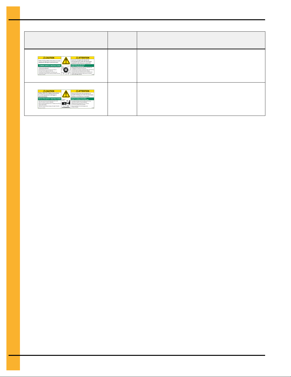
Table 1-2 Description of the grain dryer’s decals (cont'd.)
Decal Decal No. Location
This decal appears on the hitch tongue
DC-1956
This decal appears on the hitch tongue
DC-1954
Replacing Decals
All decals located on your grain dryer must remain legible and clearly visible at all times. To replace a damaged or missing decal, contact us to receive a free replacement.
GSI Decals
1004 E. Illinois St.
Assumption, IL. 62510
Tel: 1–217–226–4421
12 PNEG-1851 Vision N2
Page 13
2 The Portable Dryer
Topics Covered in this Chapter
▪ Overview of the Portable Dryer
▪ Dryer Configurations
▪ The Control Panel
▪ Overview of the User Interface
▪ Entering Parameter Values with the Keypad
Overview of the Portable Dryer
Portable dryers are modular grain dryers that can operate in batch and continuous flow, and where wet
grain is dried in a drying column that is separate from the wet grain and dried grain storage bins.
GSI portable dryers are available in multiple module configurations. For details on the different dryer configurations, see Dryer Configurations, page 15.
NOTE: Images of the dryer, control panel, and user interface menus that are included in this guide are for
illustrative purposes only and might not entirely resemble the actual product.
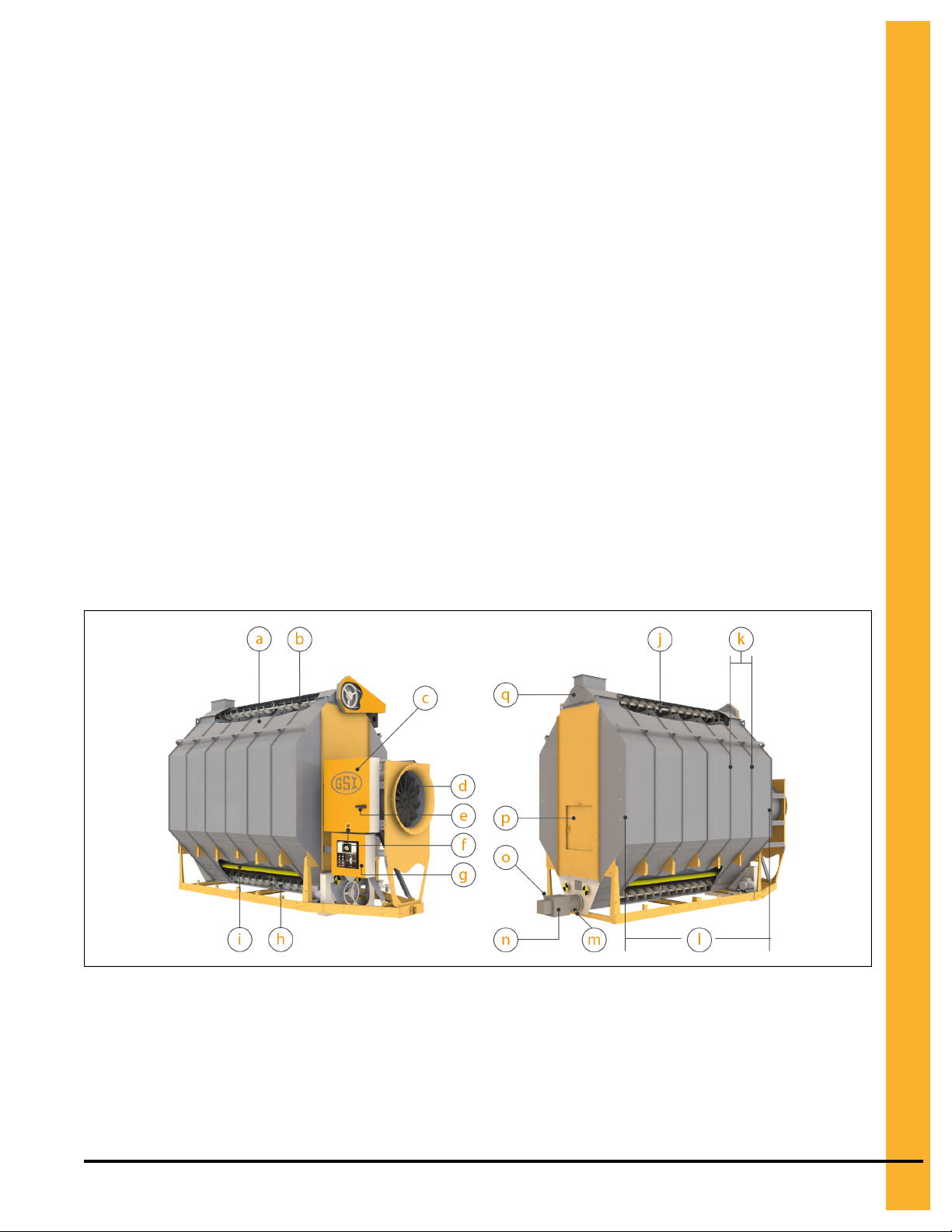
Figure 2-1 A 1-module, 1-fan portable dryer and its main components
NOTE: For definitions of the most commonly used grain drying terms, refer to this guide’s glossary.
PNEG-1851 Vision N2 13
Page 14
Chapter 2: The Portable Dryer
Table 2-1 The main components of the portable dryer
Item Name Description
a
Dryer wet bin
b Load auger The auger that distributes grain inside the dryer wet bin
c
Main control box The electrical cabinet that serves as the dryer’s power distribution panel
d Fan and heater A one-piece unit that blows hot air inside the plenum when the fan and heater are
e
Main electrical disconnect switch/
handle
f Emergency stop (e-
stop) button
g
Control panel The panel that contains the graphical user interface and all dryer control switches
h Unload auger
The compartment that maintains an adequate level of wet grain to ensure proper
air seal; contains the load auger, wet sensor, and load auger fill switch
on, and blows cool air when the heater is off and the fan is on
A safety switch that is used to turn off and lock out the main power to the dryer
A safety device used to turn off the dryer’s control power and immediately stop all
of its functions (the main power, which is controlled by the main electrical disconnect, does not turn off when you press the Emergency Stop button)
and buttons
The auger that moves the dry grain out from the unload chamber
i Metering roll
j
Load auger fill
switch
k
Grain column The column upon which the grain travels down; each grain column is 2 ft (61 cm)
l Dryer length
m
Grain sampler A manually rotatable grain outlet from which a sample of dry grain can be collected
n
Grain discharge
box
o
Dry sensor
p
Plenum access
door
q
Wet sensor
A rotating device that controls the rate at which grain moves from the grain columns to the unload auger
The limit switch that is activated once the dryer wet bin is full
wide
The combined length of all grain columns (see Configuring Your Dryer’s Hardware,
page 29 to enter this setting)
(see Validating Outgoing Moisture And Temperature Readings, page 71)
The dry grain outlet that contains the grain discharge limit switch
The sensor that measures the dry grain’s moisture; requires regular and frequent
calibrations (see Validating Outgoing Moisture And Temperature Readings, page
71)
Allows you to access the plenum chamber
The sensor that measures the wet grain’s moisture and temperature; requires regular and frequent calibrations (see Validating Incoming Moisture and Temperature
Readings, page 56)
14 PNEG-1851 Vision N2
Page 15
Chapter 2: The Portable Dryer
Make sure to turn off the main electrical disconnect switch prior to servicing your
dryer. Only the main electrical disconnect switch turns off power to the dryer and all
DANGER
electrical cabinets. Failure to do so might lead to serious injury or death.
Pressing the Emergency Stop button stops dryer functions but does not turn off the
power that is present at the various electrical cabinets. Turn off the main electrical
DANGER
disconnect switch to shut off power to the dryer and all electrical cabinets. Failure to
do so might lead to serious injury or death.
Dryer Configurations
As a result of their modular design, portable dryers are available in several fan and heater configurations,
thus making them practical in their functionality and customizable to your grain drying needs.
The following table outlines the different dryer configurations for portable dryers. Make sure to identify your
specific configuration before completing the hardware setup (see Configuring Your Dryer’s Hardware,
page 29 for details).
IMPORTANT: Make sure to enter the number of modules that corresponds to your actual dryer configura-
tion. If you enter a value that is greater or less than the actual number, the dryer will not
start because the system will search for missing or undeclared fans or heaters.
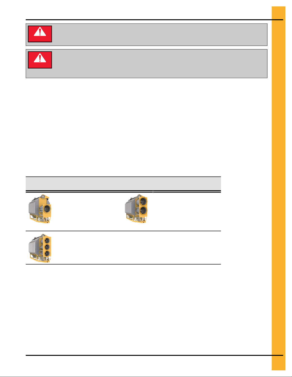
Table 2-2 The available configurations for portable dryers
Dryer configuration
Description Dryer con-
figuration
1-module, 1-fan portable
dryer
This single-module configuration includes one fan,
one heater, and one
plenum chamber
1-module, 3-fan portable dryer
This single-module configuration includes three fans, three heaters, and
three plenum chambers
Description
1-module, 2-fan portable
dryer
This single-module configuration includes two fans, two
heaters, and two plenum
chambers
PNEG-1851 Vision N2 15
Page 16
Chapter 2: The Portable Dryer
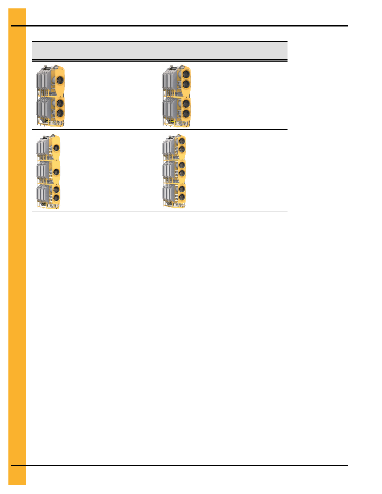
Table 2-2 The available configurations for portable dryers (cont'd.)
Dryer configuration
Description Dryer con-
figuration
2-module, 3-fan portable
dryer
This dual-module configuration includes three fans,
three heaters, and three
plenum chambers
3-module, 4-fan portable
dryer
This three-module configuration includes four fans,
four heaters, and four
plenum chambers
Description
2-module, 4-fan portable
dryer
This dual-module configuration includes four fans, four
heaters, and four plenum
chambers
3-module, 6-fan portable
dryer
This three-module configuration includes six fans, six
heaters, and six plenum
chambers
NOTE: Images of the dryer, control panel, and user interface menus that are included in this guide are for
illustrative purposes only and might not entirely resemble the actual product.
The Control Panel
Along with the touchscreen user interface, the control panel contains all buttons and switches that allow
you to set up and operate your dryer.
The following figure illustrates the Vision N2 control panel.
NOTE: Images of the dryer, control panel, and user interface menus that are included in this guide are for
illustrative purposes only and might not entirely resemble the actual product.
16 PNEG-1851 Vision N2
Page 17
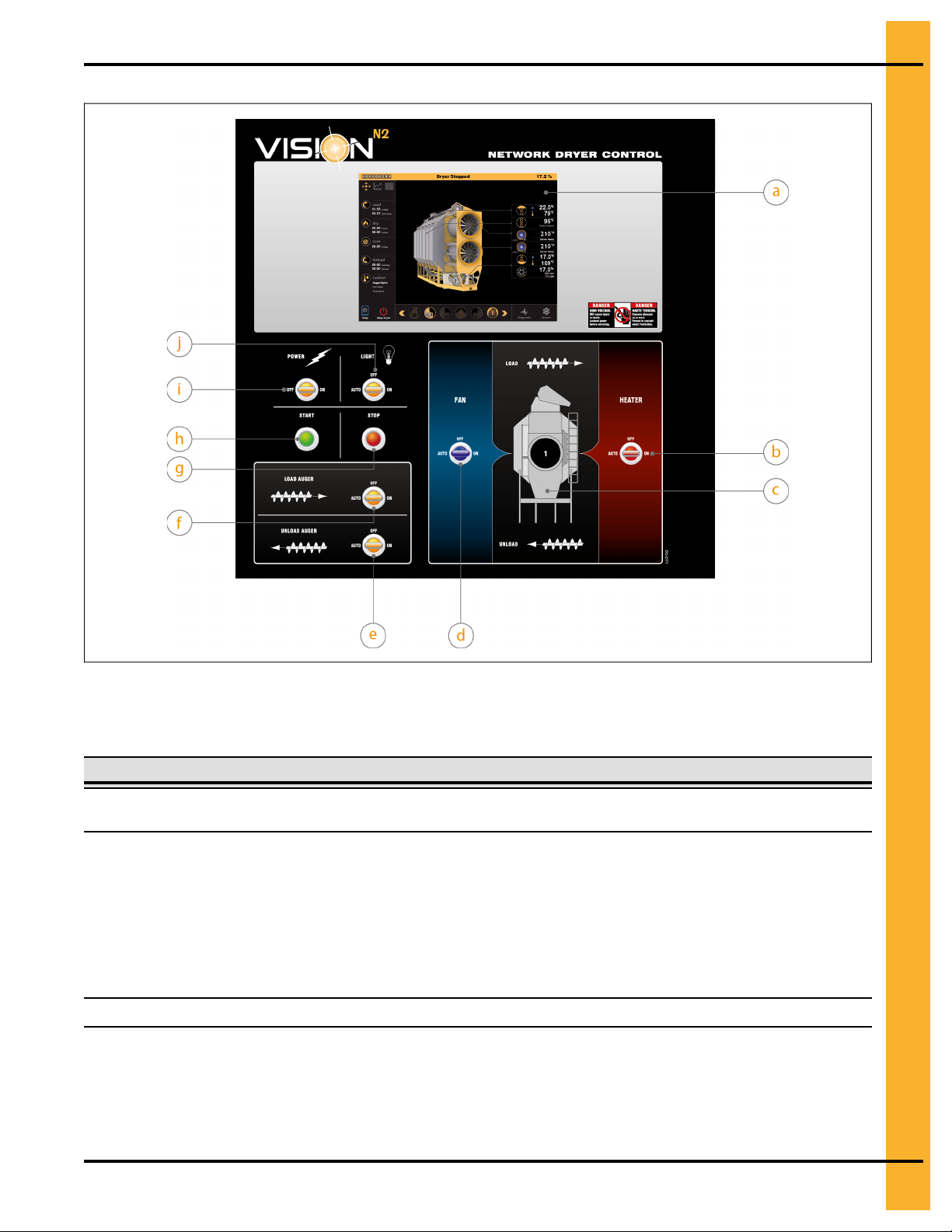
Figure 2-2 The Vision N2 control panel
Chapter 2: The Portable Dryer
NOTE: The number of fan and heater switches on your control panel depends on the number of fans and
heaters that your dryer is equipped with.
Table 2-3 The components of the control panel
Item Name Description
a
b Heater switch
c
Touchscreen
Dryer configuration A visual representation of your particular dryer configuration
Allows you to access all of the user interface menus and set all parameters
(see Overview of the User Interface, page 19 for details)
Controls the heaters by way of the following modes:
• Off: the heaters do not run
• On: the heaters run when the fans are running and air pressure is
detected
• Auto: used in staged batch mode and controlled via a timer, temperature, or both, the heaters only run during the drying phase
PNEG-1851 Vision N2 17
Page 18

Chapter 2: The Portable Dryer
Table 2-3 The components of the control panel (cont'd.)
Item Name Description
d Fan switch
e
Unload auger switch
Controls the fans by way of the following modes:
• Off: the fans do not run
• On: the fans run continuously in both continuous flow and staged
batch modes
• Auto: used in staged batch mode and controlled via a timer, temperature, or both, the fans run during the drying and cooling phases, but
turn off once the unloading phase begins
Controls the metering rolls and unload auger by way of the following modes:
• Off: the metering rolls and unload auger do not run
• On: the metering rolls only turn at one speed (in both continuous flow
and staged batch), and the unload auger operates when the metering
rolls are running; also known as manual mode (see Unloading Grain in
the Initial Run, page 33)
• Auto: in continuous flow, the metering rolls turn at the speed dictated
by the selected moisture control scheme, and the unload auger runs
continuously; in staged batch mode, the metering rolls and unload
auger only run during the unloading phase
Note the following:
Load auger switch
f
• The Unload Auger switch is illuminated whenever the unload auger is
running
• If auxiliary unloading equipment is configured and connected to your
dryer, the Unload Auger switch also controls the operation of this additional equipment.
Controls the load auger by way of the following modes:
• Off: the load auger does not run
• On: the load auger runs when the dryer is low on grain and stops when
the dryer wet bin is full; in this mode, the load delay and out of grain
timer are disabled; also known as manual mode
• Auto: the load auger runs when the dryer is low on grain and stops
when the dryer wet bin is full; in this mode, the load delay and out of
grain timer are enabled (for the load delay, see Minimizing Load Auger
Startups, page 55; for the out of grain timer, see Ensuring Dryer Shut-
downs When Supply Is Out of Grain, page 54)
Note the following:
• The Load Auger switch is illuminated whenever the unload auger is
running
• If auxiliary loading equipment is configured and connected to your
dryer, the Load Auger switch also controls the operation of this additional equipment.
18 PNEG-1851 Vision N2
Page 19
Chapter 2: The Portable Dryer
Table 2-3 The components of the control panel (cont'd.)
Item Name Description
g
Stop button Stops all dryer functions; not to be confused with Stop Dryer, which is
included in the user interface’s main menu (see Overview of the User Inter-
face, page 19 for details)
h
Start button Starts the grain drying cycle
i Power switch
j Light switch
Turns the dryer’s control power on or off
Turns the dryer’s service light on or off; in auto mode, the light remains lit
while the dryer is in operation and turns off if a shutdown situation occurs
The Power switch controls dryer functions but does not control the power that is
CAUTION
present at the various electrical cabinets. Turn off the main electrical disconnect
switch to shut off power to the dryer and all electrical cabinets.
Overview of the User Interface
The user interface allows you to access all operation and information windows via a touch-sensitive
screen. The interface includes an intuitive menu structure that allows you to easily locate parameter settings and system information.
The Main Menu
The main menu serves as a starting point for all your dryer-related operations. In addition to providing
access to all parameter settings, the main menu is easily customizable and displays essential, real-time
temperature and moisture readings. If you think that a touchscreen calibration is required while you navigate the various menus, simply access the Touchscreen Calibration submenu in the System menu and
follow the onscreen instructions. The Touchscreen Calibration submenu is not accessible when you are
operating the dryer via GSI’s remote web application.
PNEG-1851 Vision N2 19
Page 20
Chapter 2: The Portable Dryer
Settings
pane
Menu
pane
Status bar
Taskbar
01: 59
Loading
03: 27
Out of Grain
00: 00
Unloading
00: 00
Clea
nout
Tempe ratu re
Dual Sta ges
Stage d Bat ch
00: 00
Cooling
Load
Dry
Cool
Unloa d
Cont ro l
Sys
te m
Dia
gnost ic
Stop DryerHelp
95°F
22.0%
79°F
17.0%
109°F
17.0%
2000 bp h
17.0 r pm
Grain Colum n
210
/ 2 00° F
Burner Ready
1
Continuous F lo w,
Bushel Count
Moi st u re
Ou tp ut :
Dr ye r S t o ppe d 17 .2 %
9
00
a
b
c
d
s
t
e
i
j
k
f
g
h
r
q
p
o
mn
Animation
view pane
l
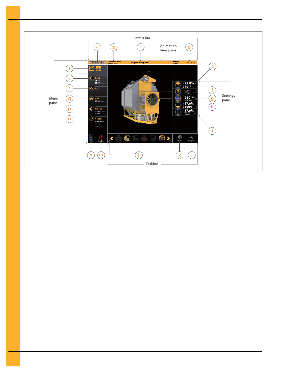
Figure 2-3 The main menu
NOTE: Due to the numerous configurations and options available, images of the dryer and its user inter-
face that are included in this guide might differ from the actual product.
20 PNEG-1851 Vision N2
Page 21

Table 2-4 Description of the main menu’s buttons and displays
Chapter 2: The Portable Dryer
Menu Area Item Name
Dry grain and staged batch
a
counter
Drying mode display
b
Status bar
Settings pane
c Dryer status display Displays the dryer’s current status
Outgoing moisture or grain
d
column temperature display
Incoming grain’s temperature/
e
moisture display
Grain column temperature
f
display
Plenum setpoint shortcut and
g
burner status display
Outgoing grain’s temperature
h
and moisture display
Description
In continuous flow, displays the total grain output; in
staged batch, displays the total batch count
Displays the selected drying mode and its associated output counter
Depending on the selected control scheme, displays
either the outgoing moisture level or the temperature
reading inside the dryer’s grain columns
Shortcut that allows you to quickly calibrate the
moisture value and the grain temperature of the wet
grain; displays the wet grain’s temperature and
moisture readings
Displays the average temperature of the grain
Shortcut that allows you to quickly modify the
plenum setpoint; displays current plenum temperature reading and burner status
Shortcut that allows you to quickly calibrate the
moisture value and the grain temperature of the dry
grain; displays the dry grain’s temperature and moisture readings
Taskbar
Shortcut that allows you to quickly modify the meter-
Metering roll speed display
i
j Diagnostic menu button Allows you to access the Diagnostic menu
System menu button Allows you to access the System menu
k
Dryer view toolbar
l
ing roll speed; displays the actual metering roll
speed
Allows you to select the dryer view that is displayed
in the animation view pane
PNEG-1851 Vision N2 21
Page 22
Chapter 2: The Portable Dryer
Table 2-4 Description of the main menu’s buttons and displays (cont'd.)
Menu Area Item Name
Stop Dryer button (remote
m
access only)
Dryer documentation button
n
o Control menu button and display
p
Menu pane
Unload menu button and display
q
Cool menu button and display
Dry menu button and display Allows you to access the Drying menu
r
s Load menu button and display
Dryer data buttons (Dryer Data:
Graph View; Dryer Data: Table
t
View)
Description
Allows you to stop the dryer via a remote connection; this button is only available on your dryer’s
remote web application, not the actual dryer
Allows you to consult the dryer’s user
documentation
Allows you to access moisture control settings; displays selected drying mode, control scheme, countdown of drying time (in staged batch only),
temperature setpoints, or a combination thereof
Allows you to access the Unloading menu; displays
a countdown of the unload time (in staged batch
only) and cleanout delay
Allows you to access the Cooling menu; displays a
countdown of the cooling timer (in staged batch
only)
Allows you to access the Loading menu; displays a
countdown of the load delay and out of grain timer
Allows you to monitor dryer data in either graph
format (on the left) or table format (on the right)
Animation
view pane
Displays the dryer view selected from the animation view toolbar; the alarm window opens here
when a shutdown fault occurs
NOTE: Regardless of which menu or submenu you are in, the status bar is always displayed atop the
active window. This allows you to constantly keep track of your dryer’s status.
How the Main Menu Works
As defined by the menu pane, grain drying is performed in the following five steps:
1. Loading the grain (Loading menu)
2. Drying/heating the grain (Drying menu)
3. Cooling the grain (Cooling menu)
4. Unloading the grain (Unloading menu)
5. Adapting dryer functions to modify the grain’s moisture content (Control menu)
NOTE: Cooling the grain inside the dryer is an optional step. Depending on your preference or grain drying
setup, you can choose to cool grain in dedicated cooling bins. See A Glance at Cooling Processes,
page 82 for more information.
To help you navigate the user interface or find the submenu for a particular setting, consider a logical,
sequenced approach to grain drying and its related tasks. Begin by answering the question: Which of the
five steps of grain drying does the topic I’m searching for apply to? For example, to configure anything pertaining to the dryer’s loading operation (out of grain timer, wet sensor calibration, etc.), simply click Load
and then choose the desired parameter from the submenu.
22 PNEG-1851 Vision N2
Page 23
Chapter 2: The Portable Dryer
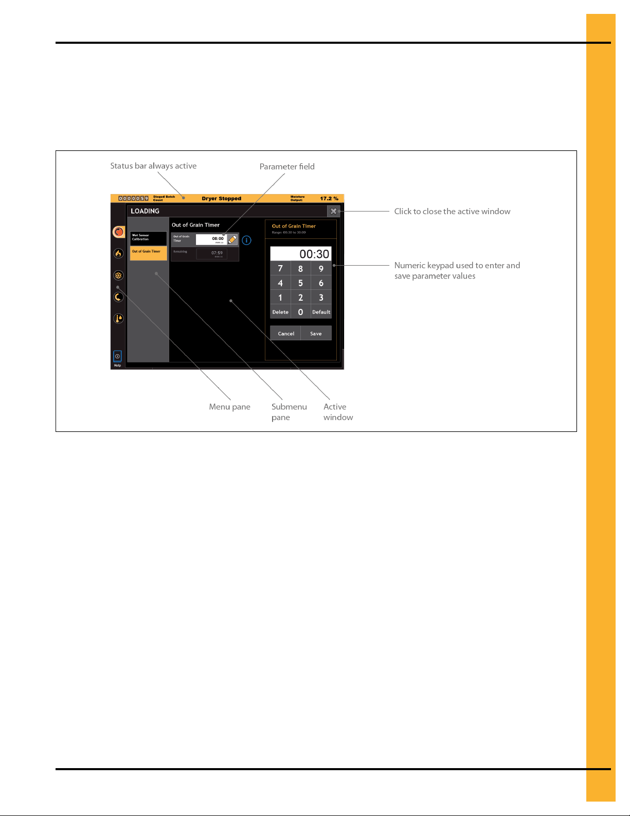
The Submenu Window
Via the various submenus, you can access and set all parameters that are required in the daily operation
of your dryer. The figure that follows illustrates a typical submenu.
Figure 2-4 The Out of Grain Timer submenu
How the Submenu Window Works
When working in submenu windows, remember the following:
• You can only access and modify parameter settings through their respective parameter fields.
• The numeric keypad is only displayed when you click the parameter field’s Edit icon, and remains
onscreen until you either save or cancel your entry. For information on how to use the keypad, see
Entering Parameter Values with the Keypad, page 24.
• When the numeric keypad is not active, a view of your dryer’s configuration is displayed.
• You must close the active submenu window to return to the main menu.
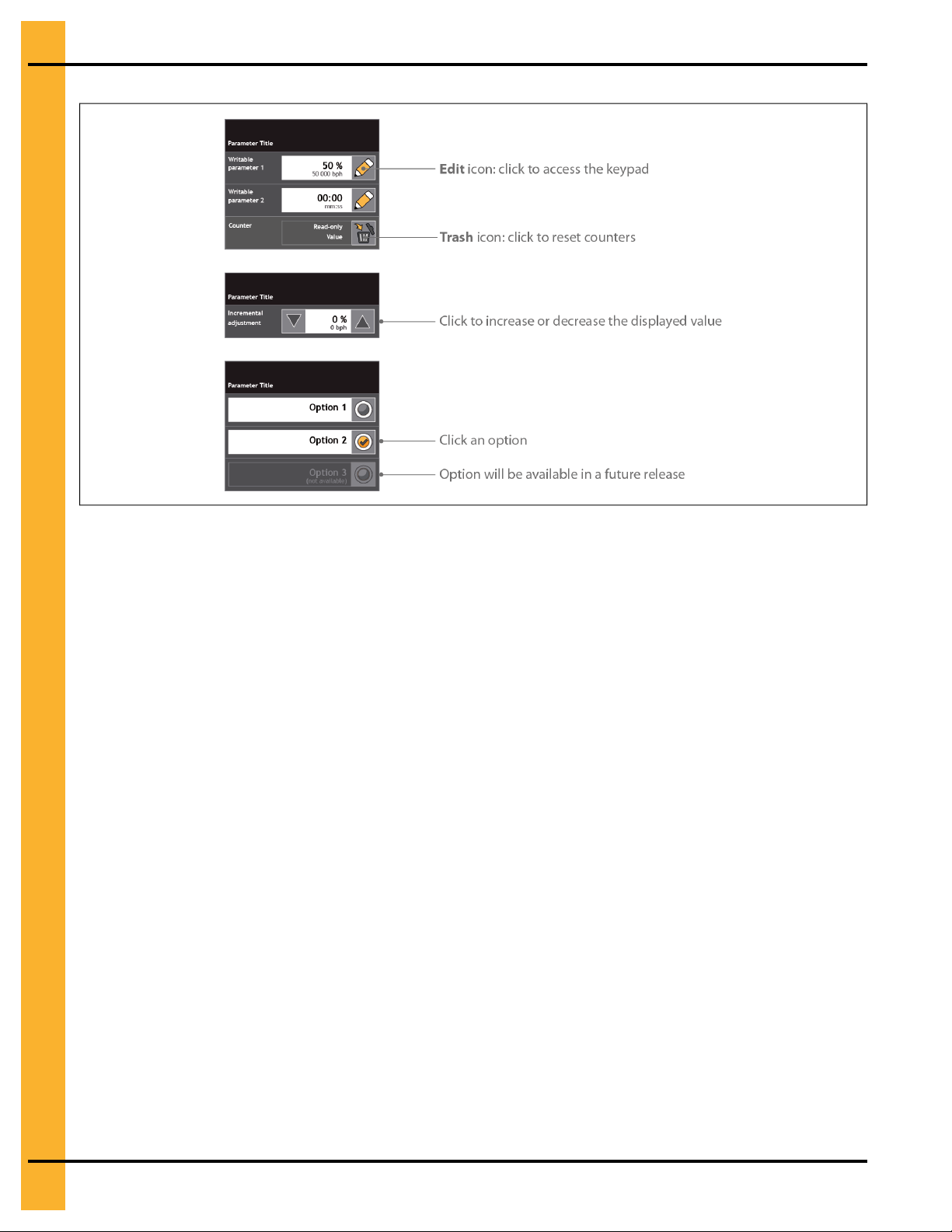
A Look at Parameter Fields
Parameter fields fall into two main categories: writable or read-only. The former allows you to enter and
modify values for specific parameters, whereas the latter merely displays a value that cannot be edited.
The figure that follows illustrates the different types of parameter fields that are available in your dryer’s
user interface.
PNEG-1851 Vision N2 23
Page 24
Chapter 2: The Portable Dryer
Figure 2-5 Samples of the various parameter fields
NOTE: Images of the dryer, control panel, and user interface menus that are included in this guide are for
illustrative purposes only and might not entirely resemble the actual product.
What You Should Know
When entering parameter values, remember the following:
• Except for the parameter shortcuts in the main menu’s system pane, the keypad is only accessible
through the Edit icon.
• The Remaining field always displays a countdown of the timer or delay that is directly above it.
Simply click its Edit icon to interrupt the countdown and enter a new value.
• When you click the Trash icon in counter fields, the displayed count is permanently erased and
cannot be retrieved.
• Not all entries made using the incremental adjustment buttons take immediate effect; some require
you to click Save to store your settings.
• In some instances, the up/down arrow buttons used for incremental adjustments might be replaced
by + and – buttons.
Entering Parameter Values with the Keypad
For parameters whose values are modifiable via the Edit icon, you can enter and save their values using
the numeric keypad.
What You Should Know
The keypad is used to enter numeric values pertaining to speed, timers or delays, and temperature or
moisture content, in a format that is unique to each type. For example, some temperature parameters
require you to enter one digit to the right of the decimal separator and others do not. Always refer to the
parameter range appearing at the top of the keypad for the required format. The following figure shows a
typical numeric keypad.
24 PNEG-1851 Vision N2
Page 25
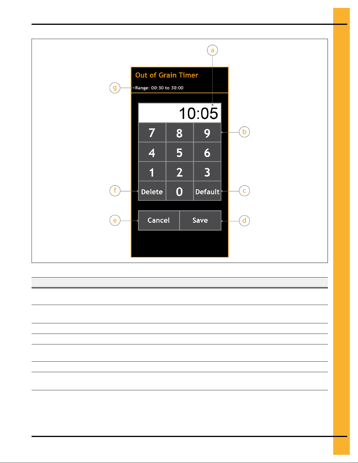
Figure 2-6 The numeric keypad for the out of grain timer
Chapter 2: The Portable Dryer
Table 2-5 Description of the keypad
Item Name
a Value display
b
c Default key Enters the parameter’s default value
d
e Cancel key
f
g
Numeric keys (0 to 9)
Save key Allows you to store the newly entered value
Delete key Allows you to clear the displayed value
Parameter range
Description
Shows the parameter’s current value once the keypad is displayed
and the new value once it is entered
Allows you to enter parameter values; entries start from the far right
of the decimal separator and move left
Allows you to exit the keypad without saving the value and return to
the active window
Displays the parameter’s allowable value range; an error message
is displayed when the entered value is out of range
To enter parameter values using the keypad:
1. From the parameter’s submenu window, click the parameter’s Edit icon.
PNEG-1851 Vision N2 25
Page 26

Chapter 2: The Portable Dryer
The keypad is displayed and the submenu window is no longer active. The parameter’s current value
is shown in the keypad’s value display.
2. Using the numeric keys, enter a new value that is within its allowable range. To enter the parameter’s
default value, click Default.
To enter 10 minutes and 5 seconds for the out of grain timer parameter,
click 1, 0, 0, 5.
The value is displayed in the keypad’s value display. If the entered value is out of range, an error
message is displayed.
3. Click Save to store the value, or click Cancel to exit without saving and return to the active window.
The keypad is no longer onscreen and the newly entered value is displayed in the respective parameter field.
NOTE: If the newly entered value is not displayed in its respective parameter field once you exit the
keypad, the value has not been stored and is not active.
26 PNEG-1851 Vision N2
Page 27

3 Getting Started
Topics Covered in this Chapter
▪ Powering On the Dryer
▪ Configuring User Preferences
▪ Configuring Your Dryer’s Hardware
▪ Setting the Dryer’s Timers and Delays
▪ Drying Grain in the Initial Run
▪ Unloading Grain in the Initial Run
Powering On the Dryer
After it has been thoroughly inspected, you can turn on your dryer to perform a touchscreen calibration, set
all of the required parameters, and begin drying grain.
Before You Begin
• Make sure that all dryer functions were properly verified and all motors, augers, belts, gear boxes,
electrical boxes, and other components were inspected by authorized maintenance personnel.
• Make sure that the Emergency Stop button on the main control box is in its fully-retracted position
(unlocked).
• If using GSI’s remote web application, make sure that the hardware setup is configured prior to starting the application (System→Hardware Setup). You must complete the hardware setup on-site
before accessing the dryer off-site.
The dryer and all of its components and functions must be in good working order
CAUTION
To power on the dryer:
1. On the control panel, turn off the following:
2. On the dryer’s main control box, place the safety disconnect switch in the On position.
3. On the control panel, turn the Power switch to On.
prior to starting the dryer. Perform thorough inspections at regular intervals,
especially when the dryer has not been in use for extended periods.
• All Fan switches
• All Heater switches
• The Load Auger switch
• The Unload Auger switch
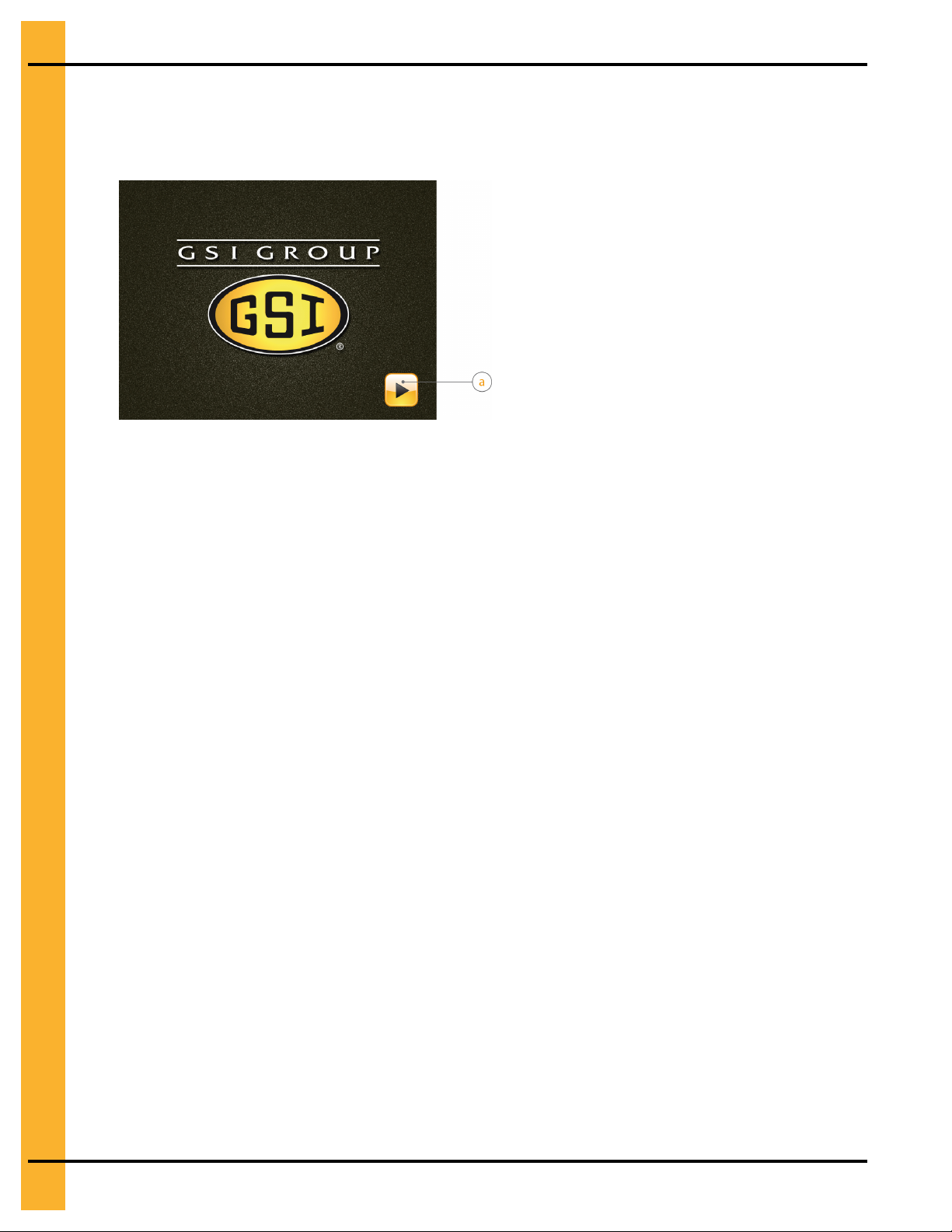
The switch is illuminated, the controller turns on, and the startup window is displayed. During this
time, no onscreen area is active.
PNEG-1851 Vision N2 27
Page 28
Chapter 3: Getting Started
NOTE: The Configuration Status dialog box is displayed in certain situations, most notably upon
startup and after clearing shutdown messages. It remains active for a few seconds before
closing automatically.
4. Once the software is ready, click the Start Software button.
If the touchscreen is calibrated, the software starts immediately and the main menu is displayed. If
not calibrated, the Touchscreen Calibration window automatically opens. Follow the onscreen instructions to successfully calibrate the touchscreen.
IMPORTANT: If the screen is too slow in reacting or your touches seem to be constantly off target,
you can calibrate the touchscreen by accessing the Touchscreen Calibration submenu in the System menu. The Touchscreen Calibration submenu is not accessible
when you are operating the dryer via GSI’s remote web application.
After You Finish
With the controller turned on, proceed as follows:
• If configuring your controller for the first time, see Configuring User Preferences, page 28.
• If performing pre-season tests, click System→Control (Advanced)→Board Mode and select Pre-
season Mode (see Pre-Season Mode, page 7 for details on this mode).
• If drying grain, see Drying Grain in the Initial Run, page 32.
IMPORTANT: If the dryer detects a fault with one or more of its components upon startup, the correspond-
ing shutdown messages are displayed onscreen. Correct them immediately before starting
the dryer.
Configuring User Preferences
Once you power on the dryer, you can set user preferences such as the system’s language and its clock,
so that onscreen content appears as desired and system logs are accurate.
To configure user preferences:
1. From the taskbar, click System→Preferences→Language.
2. Set the following parameter:
Language — The system’s language. Content in all menus and submenus appear in this language.
3. Click Save.
IMPORTANT: To store your settings, make sure to click Save before closing the active window.
28 PNEG-1851 Vision N2
Page 29

Chapter 3: Getting Started
4. From the submenu pane, click Time and Date.
5. Set the following parameters:
Time — The current time (hour; minute; a.m./p.m.).
Date — The current date (month; day; year).
IMPORTANT: Setting the correct time and date is important because the system’s clock is used by
other processes, such as your dryer’s shutdown history. As a result, incorrect time
and date settings lead to inaccurate system logs. Be sure to check the time and date
at the beginning of each drying season or when restarting the dryer after a long period
of inactivity.
6. Click Save.
7. Click Units of Measure.
8. Set the following parameter:
System Selection — The system of measurement used for all onscreen temperature, speed, and
grain measure values. The available systems of measurement are the American (or United States
customary system) and the International System (SI).
9. Click Save and close the active window.
After You Finish
Once the system settings are set, configure your dryer’s hardware setup so that the controller can properly
validate your dryer’s configuration.
Configuring Your Dryer’s Hardware
The hardware setup is a series of tangible settings that ensure your dryer’s onscreen representation accurately reflects the actual product. You can configure the hardware before the initial loading cycle, thus
avoiding potential startup faults.
Before You Begin
• Make sure that you are on-site. You cannot configure your dryer's hardware when you are operating
your dryer via GSI’s remote web application.
• Make sure that the dryer is stopped.
To configure your dryer’s hardware:
1. From the taskbar, click System→Hardware Setup.
2. Set the following parameters:
Dryer Type — The type of grain dryer that you are using (portable; tower; top).
IMPORTANT: Make sure to enter the dryer type that corresponds to your actual dryer. If you enter a
dryer type that is incorrect, a shutdown message will be displayed onscreen and you
will not be able to start the dryer.
Number of Modules — The number of modules corresponding to your portable dryer’s configuration
(1: single module; 2: two modules; 3: three modules).
PNEG-1851 Vision N2 29
Page 30

Chapter 3: Getting Started
IMPORTANT: Make sure to enter the number of modules that corresponds to your actual dryer con-
figuration. If you enter a value that is greater or less than the actual number, the dryer
will not start because the system will search for missing or undeclared fans or
heaters.
Number of Fans and Heaters — The total number of fans and heaters that are present on your portable dryer (1, 2, 3, 4, or 6).
NOTE: A portable dryer setup can contain up to three stacked modules, and each module can
include one or two fans and heaters.
Dryer Length — The length of your portable dryer (8, 12, 14, 16, 18, 20, 22, 26 ft). The dryer length
is the combined length of all grain columns and each column is 2 ft (61 cm) wide.
Loading System — The type of loading systems that is used to load grain. The available loading
systems are the following:
• Dual fill: Loads grain at both ends of the dryer wet bin and two load augers move the grain
towards the center of the dryer
• Center fill: Loads grain at the center of the dryer wet bin and two load augers move the grain
towards the front and back of the dryer
• End fill: Loads grain at one end of the dryer wet bin and one load auger evenly fills the bin
Type of Fuel — The type of fuel used to ignite the burner (diesel; vapor; natural gas; liquid propane).
Metering Roll Diameter — The diameter of your dryer’s metering rolls (4 or 7 in.). Setting the correct
diameter ensures accurate unload speeds and proper functioning in auto mode. The standard metering roll diameter is 7 in.
Metering Roll Drive Type — The drive used to control the speed and rotational force of the metering
rolls’ electric motor (DC Motor; Modbus VFD; Analog VFD).
3. Click Save and close the active window.
IMPORTANT: To store your settings, make sure to click Save before closing the active window.
Setting the Dryer’s Timers and Delays
Your dryer settings include several timers and delays pertaining to all phases of the drying process. You
can set all timers and delays before the initial run and adjust them accordingly throughout the drying
process.
What You Should Know
Certain timers and delays (for example, the unload timer) are exclusive to the staged batch drying mode
and are disabled when running in continuous flow mode. In addition, the drying time parameter is a moisture control setting specific to the time-based control schemes of the staged batch mode; as a result, the
drying time parameter is not included below. See Drying Grain in Staged Batch, page 63 for details on
accessing the staged batch control schemes.
NOTE: The Cool menu is only enabled in staged batch mode. In continuous flow mode, this menu is not
displayed in the menu pane.
30 PNEG-1851 Vision N2
Page 31

Chapter 3: Getting Started
Tip
Unless otherwise advised, it is recommended to start drying grain using the default settings for the timers
and delays. If necessary, adjust these values only after having carefully monitored all phases of the drying
cycle.
To set the timers and delays:
1. Whether in continuous flow or staged batch, click System→Cool (Advanced)→Fan Delay from the
taskbar, and set the following parameter:
Fan Delay — The delay between each fan activation. The fan delay is only available in a multiple-fan
configuration.
A fan startup draws a lot of current from the electrical grid and might cause lights to flicker in nearby
buildings. Multiple fans starting simultaneously can create even greater problems. To minimize the
voltage drop in a multi-fan configuration, set the fan delay to allow fans to start one at a time. This creates many small voltage drops instead of one big drop, thus preventing possible damage to sensitive
devices that are connected to the same electrical grid.
2. From the submenu pane, click Unload (Advanced)→Cleanout Delay and set the following
parameter:
Cleanout Delay — The length of time that the unload auger and the auxiliary unloading equipment
continue to run once the metering rolls stop. When the dryer is stopped and the cleanout delay is
counting down, pressing Stop on the control panel stops the cleanout delay.
Running the unload auger after the metering rolls have stopped ensures that the unload auger is
adequately emptied.
3. Close the active window. If running in continuous flow mode, go to step 8; if running in staged batch,
go to the next step.
4. Click Cool→Cooling Timer from the menu pane, and set the following parameter:
Cooling Timer — The length of time that the fans run to cool the grain. This timer is only available in
staged batch mode.
Tip
If running full-heat operation in staged batch mode, set the cooling timer to zero seconds to bypass
the cooling phase.
5. From the submenu pane, click Cool-Down Time and set the following parameter:
Cool-Down Time — The length of time that the fans run following a shutdown error, except when
shutdowns related to the plenums, high grain temperatures, and fan motor overloads occur; in these
instances, the cool-down time is not in effect. This timer is only available in staged batch mode.
Allowing the fans to continue to run when inconsequential shutdowns occur allows you to keep cooling the grain despite the dryer’s status. Once the shutdown message is cleared, press Start on the
control panel to restart the dryer.
6. Close the active window.
7. From the menu pane, click Unload→Unload Timer and set the following parameter:
PNEG-1851 Vision N2 31
Page 32

Chapter 3: Getting Started
Unload Timer — The length of time that the unload auger runs to unload the grain. This timer is only
available in staged batch mode.
8. To set the load delay, see Minimizing Load Auger Startups, page 55; for the out of grain timer, see
Ensuring Dryer Shutdowns When Supply Is Out of Grain, page 54.
NOTE: The Remaining field displays a countdown of the set delay or timer. Click it to interrupt the count-
down and enter a new value.
Drying Grain in the Initial Run
For the initial run, load your grain in manual mode so that you can validate its incoming moisture and
select an appropriate drying time.
Before You Begin
• Make sure that your grain loading equipment is ready to load wet grain, and that the Unload Auger
switch is in the Off position.
• Make sure that your user preferences (see Configuring User Preferences, page 28) and the hardware
setup (see Configuring Your Dryer’s Hardware, page 29) are configured.
• Set all timers and delays (see Setting the Dryer’s Timers and Delays, page 30).
• Select the moisture control mode (see Selecting a Drying Mode, page 52).
• Set the plenum temperature (see Setting the Plenum Temperature Range, page 35).
• Select the burner mode (see The Burner Modes, page 79).
To dry grain in the initial run:
1. To begin loading grain, turn the Load Auger switch to On.
The switch is illuminated, the load auger starts, and the grain loading equipment also starts after a
brief delay. Manual mode is enabled for the loading phase.
NOTE: To avoid out of grain shutdowns, the load delay and out of grain timer are bypassed in
manual mode.
2. As the wet grain enters the dryer wet bin, obtain a sample to measure the actual incoming moisture
(see Validating Incoming Moisture and Temperature Readings, page 56 for details).
When the dryer is full of grain (the load auger fill switch is activated), the load auger and grain loading
equipment stop.
3. Open the following valves:
• The tank’s main fuel supply valve (if using liquid propane as a fuel source); or the valve in the
fuel supply line (if using natural gas as a fuel source)
• The automatic electric shutoff valve or the manual shutoff valve (depending on which one your
dryer is equipped with)
4. Turn the Load Auger switch to Auto.
With the Load Auger switch in either the Auto or On positions, the controller and load auger fill
switch ensure that the dryer is always kept full of grain.
IMPORTANT: When the Load Auger switch is in the On position, the out of grain timer is bypassed.
As a result, out of grain shutdowns do not occur.
32 PNEG-1851 Vision N2
Page 33

Chapter 3: Getting Started
5. Turn all Fan switches to On.
The fans start and the switches are illuminated once air pressure is detected.
Tip
It is recommended to start fans one at a time, and to let each fan attain their respective speed before
starting the next one.
6. Turn all Heater switches to On, and confirm that all plenum setpoints are set (see Setting the Plenum
Temperature Range, page 35).
After a 15-second purge for safety reasons, the burners ignite and the switches are illuminated.
7. Run the burners for the drying time indicated in the drying operation’s respective startup settings (see
Initial Settings for Full-Heat and Dry and Cool, page 78).
When establishing drying times, the rule of thumb is to dry grain for five to seven minutes for each point of
moisture you need to remove. Let’s assume that the wet grain has a moisture content of 25%, a target of
15%, and that you are running a full-heat operation. According to the startup settings, you need to dry
grain for 54 minutes.
If running dry and cool, turn off the bottom heater once the drying time elapses, and run the dryer for an
additional 10 minutes so that the grain can cool.
After You Finish
Unload grain in manual mode before switching to auto mode (see Unloading Grain in the Initial Run, page
33). For information on drying grain in auto mode, see Drying Grain in Continuous Flow, page 57 (for con-
tinuous flow) or Drying Grain in Staged Batch, page 63 (for staged batch).
Unloading Grain in the Initial Run
For the initial run, unload the dry grain in manual mode so that you can validate the outgoing moisture content and establish an appropriate unload rate prior to switching to auto mode.
Before You Begin
• Make sure to set all required parameters; see Powering On the Dryer, page 27 for information on
which parameters to set.
• If running dry and cool, ensure that the set drying time and cooling time have elapsed (see Drying
Grain in the Initial Run, page 32 for details).
What You Should Know
In manual mode, only one unload speed is available, regardless of the chosen control scheme; whereas in
auto mode (Unload Auger switch in the Auto position), you can enter unload speeds in the settings
window of the chosen control scheme.
To unload grain in the initial run:
1. From the menu pane, click Unload→Unload Speed.
The Unload Speed in Manual Mode window opens.
2. Set the following parameters:
Unload Speeds Entered in — The units of measure (bushels or metric tons per hour, or metering
roll speed %) that the unload speed value is entered in.
PNEG-1851 Vision N2 33
Page 34

Chapter 3: Getting Started
Adjusted Speed — The speed that the metering rolls turn at when the Unload Auger switch is in the
On position. Enter the speed value that corresponds to your dryer’s configuration and your chosen
drying operation (full-heat or dry and cool).
See Setting the Value Range for the Unload Speed, page 73 for information on the minimum and
maximum limits for the unload speed.
Incremental Adjustment — The incremental adjustment of the metering roll speed in manual mode.
NOTE: See Initial Settings for Full-Heat and Dry and Cool, page 78 for startup settings for both the
full-heat and dry and cool operations.
3. Turn the Unload switch to On.
Manual mode is enabled for the unloading phase and dry grain begins to unload.
4. As dry grain exits the dryer, obtain a sample to measure the actual outgoing moisture (see Validating
Outgoing Moisture And Temperature Readings, page 71 for details).
5. If running in continuous flow, run a second complete cycle and repeat step 4 before proceeding. If
running in staged batch, proceed to step 6.
6. Based on the resulting moisture content, adjust the plenum temperature according to your dryer
configuration.
If running in full-heat with a three-fan dryer, you can stage the plenum temperatures 30 degrees apart
—highest temperature at the top plenum and lowest at the bottom (for example, from top to bottom:
230°F, 200°F, 170°F).
7. Obtain another sample of dry grain as it exits the dryer and re-validate its moisture content.
8. Once you are outputting the desired moisture content, turn the Unload Auger switch to Auto.
Let’s assume that the wet grain has a moisture content of 25%, a target of 15%, and that you are running a
full-heat operation with a two-module dryer configuration. According to the startup settings, set an unload
speed of 390 bph after having dried the grain for 54 minutes.
34 PNEG-1851 Vision N2
Page 35

4 Basic Operations
Topics Covered in this Chapter
▪ Setting the Plenum Temperature Range
▪ Resetting the Dry Grain Counters
▪ Shutting Off the Dryer at the End of the Day
▪ Shutting Off the Dryer at the End of the Drying Season
▪ Monitoring Grain and Dryer Data in Real Time
▪ Downloading Dryer Data to a USB Flash Drive
Setting the Plenum Temperature Range
The plenum setpoint and burner differential settings establish the temperature range inside the plenum.
You can set this range before the initial run and adjust if the grain temperature rises or drops excessively.
To set the plenum temperature range:
1. From the menu pane, click Dry→Plenum Setpoints.
NOTE: The plenum setpoint window that opens is dependent on the chosen drying mode. For exam-
ple, the second group of plenum setpoints is only displayed when a dual-setpoint control
scheme is selected within the staged batch drying mode.
2. Set the following parameter:
Plenum Setpoints — The desired temperature inside the plenum. In a multi fan and heater configuration, plenum 1 always refers to the one that is closest to ground level.
NOTE: To access and enter plenum setpoints from the main menu quickly, click the plenum’s respec-
tive setpoint shortcut that is located in the settings pane.
3. Close the active window.
4. From the taskbar, click System→Dry (Advanced)→Burner Differential.
5. Set the following parameter:
Burner Differential — The offset from the target temperature that establishes the minimum and maximum plenum setpoint limits. When these limits are attained, the burner’s reaction is dependent on
the chosen burner mode.
Let’s assume that you enter a plenum setpoint of 210°F, a burner differential value of +/- 1°F, and choose
either the high/low or on/off burner operating mode. When the plenum’s actual temperature reaches 211°F,
the burner switches to either low fire (high/low mode) or shuts off (on/off mode). In both modes, the burner
switches back to high fire when the plenum temperature drops to 209°F.
After You Finish
Select a burner mode to help you establish and maintain a uniform plenum temperature (see The Burner
Modes, page 79).
PNEG-1851 Vision N2 35
Page 36

Chapter 4: Basic Operations
Resetting the Dry Grain Counters
The dry grain and staged batch counters keep track of unloaded grain. You can reset these counters at
any time, allowing you to keep count of grain unloaded for a particular harvest or work period.
IMPORTANT: Resetting a counter permanently erases its total count and it cannot be retrieved.
To reset the dry grain counters:
1. From the menu pane, click System→Unload (Advanced)→Dry Grain Counter.
2. Reset the following count:
Total Dry Grain Count — The total count of dry grain tallied from the last grain counter reset. The
total count also includes that from the staged batch counter.
The counter displays 0.
NOTE: The units of measure selection (bushels or metric tons per hour) that is displayed in this field
is dependent on the chosen system of measurement (System→Preferences→Units of
Measure).
3. If in staged batch mode, click Staged Batch Counter from the submenu pane.
4. Reset the following count:
Total Batch Count — The total number of batches tallied from the last batch counter reset. Available
only in staged batch mode, a batch is the quantity of grain that is discharged in one unloading
operation.
The counter displays 0.
Shutting Off the Dryer at the End of the Day
A proper daily shutoff procedure prolongs the life of your equipment and ensures your safety. You can shut
off the dryer according to your established policies or when instructed to do so for maintenance purposes.
What You Should Know
To properly shut off the dryer at the end of the day you must be present at the control panel. However, it is
also possible to stop the dryer when you are off-site, via GSI’s remote web application. To stop your dryer
through this remote application, simply click Stop Dryer from the main menu, and then click Yes when
prompted to confirm your action.
IMPORTANT: Once you have stopped the dryer via the remote web application, you cannot restart it
remotely. The dryer can only be restarted on-site.
The ensuing procedure assumes that you will continue to dry grain in the days that follow, and that the
dryer will not be off for an extended period. To shut off the dryer at the end of the drying season, see Shut-
ting Off the Dryer at the End of the Drying Season, page 37.
To shut off the dryer at the end of the day:
1. Turn off the following, in sequence:
a. The Load Auger switch
b. All Heater switches, from top to bottom
c. The Unload Auger switch
2. Run the fans for 15 to 20 minutes to cool the dryer.
36 PNEG-1851 Vision N2
Page 37

Chapter 4: Basic Operations
3. Once the dryer has cooled off, close the dryer’s fuel valve.
4. On the control panel, press Stop .
All dryer functions stop.
Shutting Off the Dryer at the End of the Drying Season
You can shut off the dryer at the end of the drying season to ensure that your equipment can safely remain
inactive until the start of the next drying season.
Before You Begin
Make sure that there is no grain in the dryer and in the wet grain storage bin.
The ensuing procedure assumes that you will not dry grain in the days that follow, and that the dryer will be
off for an extended period. To shut off the dryer at the end of the day, see Shutting Off the Dryer at the End
of the Day, page 36.
To properly shut off the dryer at the end of the drying season you must be present at
CAUTION
the control panel. Stopping the dryer via GSI’s remote web application only stops
dryer functions—the dryer’s main power is still on.
To shut off the dryer at the end of the drying season:
1. Turn off the following, in sequence:
a. The Load Auger switch
b. All Heater switches, from top to bottom
c. All Fan switches, from top to bottom
d. The Unload Auger switch
2. If using liquid propane, close the tank’s fuel supply valve; if using natural gas, close the fuel line
valve.
3. If the burner is on, let the dryer run out of fuel.
Once it is out of fuel, the burner automatically shuts off because it no longer detects a flame.
4. Close the dryer’s fuel valve, and then press Stop on the control panel.
All dryer functions stop.
5. Turn the Power switch to Off.
The control power turns off and the controller shuts down.
6. Place the main electrical disconnect switch in the Off position, and then turn off the dryer’s main
power.
The main power that is present at the electrical cabinets turns off.
The Power switch controls dryer functions but does not control the power that is
CAUTION
After You Finish
PNEG-1851 Vision N2 37
present at the various electrical cabinets. Turn off the main electrical disconnect
switch to shut off power to the dryer and all electrical cabinets.
Page 38

Chapter 4: Basic Operations
Make sure to thoroughly inspect and clean the dryer’s various components such as the metering rolls,
augers, and motors. You can follow your established procedures or contact the GSI Group, LLC for specific
instructions.
Monitoring Grain and Dryer Data in Real Time
To obtain a graphical or tabular representation of grain drying statistics in real time, you can set your
desired data monitoring parameters, and also transfer the data to your personal computer or local network
to keep a record of these statistics.
What You Should Know
You can monitor various grain and dryer data through either the Dryer Data: Table View or Dryer Data:
Graph View windows, both of which are available in continuous flow and staged batch mode. However,
you can only set the time and date that you want to start collecting data by, in the Dryer Data: Table View
window. Access these windows by clicking on their respective buttons in the main menu (see Overview of
the User Interface, page 19).
To monitor grain and dryer data in real time:
1. From the menu pane, click on the Dryer Data: Table View button.
2. Click on Date.
3. Set the time and date to start collecting data by, then click Apply.
The window closes and Live is now displayed at the bottom left corner of the active window.
4. Click Live to get the current data.
The data within the table is updated and Live is no longer displayed.
5. Set the following parameters:
Interval — The length of interrupted time that the controller collects grain and dryer data.
Sampling Rate — The frequency at which the controller collects grain and dryer data.
NOTE: The sampling rate varies according to the chosen interval. For example, you can only select a
sampling rate of 10 minutes for an interval setting of 48 hours; however, for a interval setting
of 4 hours, you can choose sampling rates of 1 minute, 5, minutes, or 10 minutes.
6. Click the check mark to apply the settings.
Let’s assume that you want to monitor the moisture content of the wet grain over a 24-hour period, and you
want samples to be collected every 5 minutes. Set the interval at 24 hr. and the sampling rate at 5 min.
Downloading Dryer Data to a USB Flash Drive
To keep a record of statistics, such as the grain’s moisture content over a set interval of time, you can
download dryer data from the controller and then transfer the information to your personal computer or
local network.
Before You Begin
38 PNEG-1851 Vision N2
Page 39

Chapter 4: Basic Operations
• Make sure to set the interval and sampling rate settings through either the Dryer Data: Table View or
Dryer Data: Graph View windows (see Monitoring Grain and Dryer Data in Real Time, page 38).
• Make sure that the dryer is powered on.
• Make sure that the USB (Universal Serial Bus) flash drive is formatted to FAT32 (32-bit File Allocation
Table).
To download dryer data to a USB flash drive:
1. Open the control panel door and locate the single-board computer (SBC) board.
Use extreme caution when opening the control panel door with the dryer
CAUTION
into a USB port.
2. Insert the USB flash drive in an available USB port on the SBC board then return to face the control
panel.
A message notifying you that the downloading process is set to begin is displayed onscreen. The
data that is downloaded is that which is present in the database at the time of download.
powered on. To avoid electrical shock and potential damage to the board, do not
touch the board with tools or with your hands when inserting the USB flash drive
IMPORTANT: Do not remove the USB flash drive until the transfer is complete.
3. Once a message notifying you that the download was successful is displayed onscreen, remove the
USB flash drive.
A compressed data file (ZIP) that contains a file in the comma separated value (CSV) format is saved
to your USB flash drive.
4. Close the control panel door and make sure that it is secure.
After You Finish
Transfer the data to your personal computer or local network, so that you can compile and track grain and
dryer information.
PNEG-1851 Vision N2 39
Page 40

NOTES
40 PNEG-1851 Vision N2
Page 41

5 The Drying Modes
Topics Covered in this Chapter
▪ Continuous Flow Mode
▪ Staged Batch Mode
▪ Selecting a Drying Mode
Continuous Flow Mode
The continuous flow mode is a grain drying method where grain enters and exits the dryer in one continuous, uninterrupted cycle. Consequently, the metering rolls turn constantly, at a speed defined by the control
parameters.
As with any drying mode, the main objective is to obtain the appropriate outgoing moisture content for the
type of grain that you are drying. This is accomplished by passing heated air through the grain, thus lowering the moisture level. In continuous flow drying, wet grain is loaded in the dryer wet bin, dried in the grain
columns, and then either cooled and unloaded (in dry and cool operation), or simply unloaded and then
cooled in external cooling bins (in full-heat operation). For details on the full-heat and dry and cool operations, see Grain Drying: Full-Heat or Dry and Cool, page 80.
Control Parameters
In continuous flow, the dryer monitors the following two control parameters in an attempt to attain consistent outgoing moisture:
• Grain temperature
• Outgoing grain moisture
Depending on actual temperature and moisture readings obtained during the drying process, the dryer’s
unload speed is automatically adjusted via preset control schemes. Increasing or decreasing the unload
speed affects the length of time that the grain remains in the dryer, thereby resulting in heating the grain
more or heating it less.
Control Schemes
Control schemes are preset drying strategies designed to aid the user in achieving the desired outgoing
moisture content. Each control parameter has specific control schemes to choose from. The figure that follows shows the control schemes that are available for each control parameter.
PNEG-1851 Vision N2 41
Page 42

Chapter 5: The Drying Modes
Figure 5-1 Breakdown of the control parameters and schemes in the continuous flow mode
Continuous Flow Based on Grain Temperature
Temperature-based control schemes in continuous flow use the grain temperature as their reference
parameter. As the grain temperature rises or drops, the unload speed automatically adjusts according to
the selected control scheme.
How It Works
Grain temperature is directly proportional to grain moisture. The unload rate changes to keep the grain
temperature constant, thus controlling the moisture output.
Let’s assume a grain temperature setpoint of 105°F. If the dryer reports a grain temperature reading of
110°F, the grain is five degrees higher than the target temperature. To correct this, the selected control
scheme automatically increases the unload speed, thereby reducing the length of time that the grain
spends in the grain columns. The opposite is also true. If the dryer reports a grain temperature reading of
100°F (five degrees below the setpoint), the unload speed automatically decreases.
The following three temperature-based control schemes are available in continuous flow mode:
• 1-speed
• 2-speed
• 5-speed
The 1-Speed Control Scheme
In the 1-speed control scheme, you enter the following parameters:
• The metering roll speed setpoint
• The grain temperature setpoint
As shown in the figure that follows, the metering rolls turn at the speed setpoint if the grain temperature is
equal to the grain temperature setpoint, and shut off if the grain temperature drops 1°F (0.56°C) below its
setpoint. See Setting the 1-Speed Temperature Scheme in Continuous Flow, page 58 for details on how to
set up this control scheme.
42 PNEG-1851 Vision N2
Page 43

Chapter 5: The Drying Modes
Figure 5-2 Speed versus temperature relationship for the 1-speed temperature control scheme
The 2-Speed Control Scheme
In the 2-speed control scheme, you enter the following parameters:
• The low metering roll speed
• The high metering roll speed
• The grain temperature setpoint
As shown in the figure that follows, the metering rolls turn at the high speed setting if the grain temperature
is 1°F (0.56°C) above its setpoint, or they run at the low speed setting if the grain temperature is 1°F (0.56°
C) below its setpoint. The 2-speed temperature control scheme is a precursor to the more comprehensive
5-speed schemes in continuous flow. See Setting the 2-Speed Temperature Scheme in Continuous Flow,
page 59 for details on how to set up this control scheme.
PNEG-1851 Vision N2 43
Page 44

Chapter 5: The Drying Modes
Figure 5-3 Speed versus temperature relationship for the 2-speed temperature control scheme
The 5-Speed Control Scheme
In the 5-speed control scheme, you enter the following parameters:
• The reference speed
• The grain temperature setpoint
• The metering roll speed’s inner offset
• The metering roll speed’s outer offset
• The grain temperature’s inner offset
• The grain temperature’s outer offset
As shown in the following figure, the 5-speed temperature control scheme uses five speed settings to
obtain the target moisture content, and the speed that is selected is dependant on the measured grain
temperature. If the grain temperature exceeds the measured temperature, higher speeds are automatically
selected. Conversely, if the grain temperature is below its setpoint, lower speeds are automatically
selected. This control scheme expands on the 2-speed scheme, creating a more dynamic moisture control
scheme that can accommodate a wider variation of incoming grain moisture. See Setting the 5-Speed
Temperature Scheme in Continuous Flow, page 60 for details on how to set up this control scheme.
44 PNEG-1851 Vision N2
Page 45

Chapter 5: The Drying Modes
Figure 5-4 Speed versus temperature relationship for the 5-speed temperature control scheme
Continuous Flow Based on Grain Moisture
Moisture-based control schemes in continuous flow use grain moisture as their reference parameter. As
the grain’s moisture content rises or drops, the unload speed automatically adjusts according to the
selected control scheme
How It Works
As opposed to grain temperature, the dryer’s unload rate is inversely proportional to the grain’s moisture
content—as the moisture rises, the unload rate decreases. The grain’s moisture content is monitored by
the dry sensor, which is located next to the grain discharge box.
Let’s assume a grain moisture setpoint of 15%. If the dry sensor reports a moisture reading of 16%, the
grain is one percentage point higher than the target moisture content. As a result, the selected control
scheme automatically decreases the unload speed, thereby increasing the length of time that the grain
spends in the grain columns. The opposite is also true. If the dry sensor reports a grain moisture reading of
14% (one percentage point below the setpoint), the unload speed automatically increases.
The 5-Speed Control Scheme
The 5-speed control scheme is the moisture-based scheme that is available in continuous flow. In this control scheme, you enter the following parameters:
• The reference speed
• The grain moisture setpoint
• The metering roll speed’s inner offset
PNEG-1851 Vision N2 45
Page 46

Chapter 5: The Drying Modes
• The metering roll speed’s outer offset
• The grain moisture’s inner offset
• The grain moisture’s outer offset
As shown in the following figure, the 5-speed moisture control scheme uses five speed settings to obtain
the target moisture content, and the speed that is selected is dependant on the measured grain moisture.
If the grain’s moisture content exceeds the measured moisture, lower speeds are automatically selected.
Conversely, if the grain’s moisture content is below its setpoint, higher speeds are automatically selected.
See Setting the 5-Speed Moisture Scheme in Continuous Flow, page 61 for details on how to set up this
control scheme.
Figure 5-5 Speed versus moisture relationship for the 5-speed moisture control scheme
Staged Batch Mode
The staged batch (SB) drying process is a grain drying method comprised of three distinct phases, where
only a portion of the grain is loaded and unloaded at a single time.
As with any drying mode, the main objective is to obtain the appropriate outgoing moisture content for the
type of grain that you are drying. This is accomplished by passing heated air through the grain, thus lowering the moisture level. In staged batch, every phase of the drying process is performed separately: the wet
grain is first loaded into the dryer, dried in the grain columns, and then either cooled and unloaded (in dry
and cool operation), or simply unloaded and then cooled in external cooling bins (in full-heat operation
only). For details on the full-heat and dry and cool operations, see Grain Drying: Full-Heat or Dry and
Cool, page 80.
46 PNEG-1851 Vision N2
Page 47

Chapter 5: The Drying Modes
Control Parameters
In staged batch, the dryer monitors the following two control parameters:
• Grain temperature
• Drying time
Control Schemes
Control schemes are preset drying strategies designed to aid the user in achieving the desired outgoing
moisture content. Each control parameter has specific control schemes to choose from. The figure that follows shows the control schemes that are available for each control parameter.
Figure 5-6 Breakdown of the control parameters and schemes in the staged batch mode
A Glance at the Full-Heat and Dry and Cool Operations in Staged Batch
The full-heat drying operation allows you to discharge uncooled, hot grain and manage the grain cooling
process outside the confines of the physical dryer. To operate your dryer using full-heat, all Fan and
Heater switches on the control panel are set to On and the Cooling Timer is set to 0 seconds. Conversely,
dry and cool allows you to completely dry and cool the grain within the dryer and, in doing so, unload dry
grain that is relatively close to the ambient temperature. To operate your dryer using dry and cool in staged
batch mode, all Fan and Heater switches on the control panel are set to Auto. For more information about
the full-heat and dry and cool operations, see Grain Drying: Full-Heat or Dry and Cool, page 80.
Staged Batch Based on Drying Time
Timer-based control schemes in staged batch use timers as their reference parameter. Use these
schemes when you would like timers to dictate the dryer’s heat level, and the grain’s exposure to heat not
to surpass a certain length of time.
How It Works
In timer-based control schemes, a drying timer starts at the beginning of the drying phase. During this
phase, allfans and heaters are activated so that theplenums can reach their respective setpoints. The
drying phase continues until the drying timer elapses. Once it has elapsed, the heaters stop, the drying
phase ends, and then the cooling and unloading phases follow one after the other.
The Time Control Scheme
In the time control scheme, you enter the following parameters:
PNEG-1851 Vision N2 47
Page 48

Chapter 5: The Drying Modes
• The drying time
• The temperature setpoint of each plenum
As shown in the figure that follows, the drying phase starts when the load auger fill switch is activated and
stops when the drying time elapses. A cooling phase immediately follows, and the dry and cool grain is
then discharged from the dryer during the unloading phase.
Figure 5-7 Time control scheme in the dry and cool operation
NOTE: In full-heat operation, the cooling phase is simply bypassed. As a result, the unloading phase
starts immediately following the drying phase, allowing uncooled, hot grain to be discharged from
the dryer.
The Dual-Setpoint Time Control Scheme
In the dual-setpoint time control scheme, you enter the following parameters:
• The drying time 1
• The drying time 2
• The temperature setpoint of each plenum for the first part of the drying phase (plenum setpoints 1)
• The temperature setpoint of each plenum for the last part of the drying phase (plenum setpoints 2)
As shown in the figure that follows, the drying phase starts when theload auger fill switch is activated. All
fans and heaters turn on so that the plenums can reach the temperature setpoints that are defined for the
first part of the drying phase. Once drying time 1 elapses, drying time 2 starts, and the heat intensity is typically reduced to enhance grain quality. The drying phase ends once drying time 2 elapses. A cooling
phase immediately follows, and the dry and cool grain is then discharged from the dryer during the unloading phase.
48 PNEG-1851 Vision N2
Page 49

Chapter 5: The Drying Modes
Figure 5-8 Dual-setpoint time control scheme in the dry and cool operation
NOTE: In full-heat operation, the cooling phase is simply bypassed. As a result, the unloading phase
starts immediately following the drying phase, allowing uncooled, hot grain to be discharged from
the dryer.
Staged Batch Based on Grain Temperature
Temperature-based control schemes in staged batch use grain temperature sensors as their reference
parameter. Use these schemes when you would like the grain temperature to dictate the moisture content
and unload grain at a specific temperature.
How It Works
During the drying phase, all fans and heaters are activated so that the plenums can reach their respective
setpoints. The drying phase continues until the grain temperature reaches a defined temperature setpoint.
Once this setpoint is reached, the heaters stop, the drying phase ends, and then the cooling and unloading
phases follow one after the other.
To better control the grain’s final temperature, it is also possible to alter the plenum setpoint when the grain
temperature reaches a predefined temperature. By doing so, the wet grain is exposed to two different
drying temperatures within the same drying phase. The drying phase ends when the grain temperature
reaches its final temperature setpoint (see The Dual-Setpoint Temperature Control Scheme, page 50 for
details).
The Temperature Control Scheme
In the temperature control scheme, you enter the following parameters:
• The grain temperature setpoint
• The temperature setpoint of each plenum
As shown in the following figure, the drying phase starts when the load auger fill switch is activated and
stops when the grain temperature reaches its setpoint. A cooling phase immediately follows, and the dry
and cool grain is then discharged from the dryer during the unloading phase.
PNEG-1851 Vision N2 49
Page 50

Chapter 5: The Drying Modes
Figure 5-9 Temperature control scheme in the dry and cool operation
NOTE: In full-heat operation, the cooling phase is simply bypassed. As a result, the unloading phase
starts immediately following the drying phase, allowing uncooled, hot grain to be discharged from
the dryer.
The Dual-Setpoint Temperature Control Scheme
In the dual-setpoint control scheme, you enter the following parameters:
• The grain setpoint 1
• The grain setpoint 2
• The temperature setpoint of each plenum for the first part of the drying phase (plenum setpoints 1)
• The temperature setpoint of each plenum for the last part of the drying phase (plenum setpoints 2)
As shown in the following figure, the drying phase starts when theload auger fill switch is activated. In addition, all fans and heaters turn on so that the plenums can reach plenum setpoint 1. When the grain temperature reaches grain setpoint 1, the second part of the drying phase begins and the heat intensity is
reduced. This reduction makes the drying process less aggressive, thus resulting in better quality grain.
The drying phase ends when the grain temperature reaches grain setpoint 2. A cooling phase immediately
follows, and the dry and cool grain is then discharged from the dryer during the unloading phase.
50 PNEG-1851 Vision N2
Page 51

Chapter 5: The Drying Modes
Figure 5-10 Dual-setpoint temperature control scheme in the dry and cool operation
NOTE: In full-heat operation, the cooling phase is simply bypassed. As a result, the unloading phase
starts immediately following the drying phase, allowing uncooled, hot grain to be discharged from
the dryer.
Staged Batch Based on Drying Time and Grain Temperature
The time and temperature control scheme in staged batch uses the first reached of these two control
parameters to dictate the duration of the drying phase. Use this control scheme when both the drying time
and the dry grain’s temperature must not surpass a certain value.
In the time and temperature control scheme, you enter the following parameters:
• The drying time
• The grain temperature setpoint
• The temperature setpoint of each plenum
As shown in the figure that follows, the drying phase starts when theload auger fill switch is activated, and
stops when the grain temperature reaches its setpoint or after the drying time elapses, whichever comes
first. A cooling phase immediately follows, and the cool grain is then discharged from the dryer during the
unloading phase.
PNEG-1851 Vision N2 51
Page 52

Chapter 5: The Drying Modes
Figure 5-11 Time and temperature control scheme in the dry and cool operation
NOTE: In full-heat operation, the cooling phase is simply bypassed. As a result, the unloading phase
starts immediately following the drying phase, allowing uncooled, hot grain to be discharged from
the dryer.
Selecting a Drying Mode
Before drying grain, you can select a drying mode to determine how wet grain passes through the dryer
and exits as dry grain.
To select a drying mode:
1. From the menu pane, click Control→Moisture Control Mode.
2. Select one of the following parameters:
Continuous Flow — A drying mode where grain enters and exits the dryer in one continuous, uninterrupted cycle.
Staged Batch — A drying mode comprised of three distinct phases, where only a portion of the grain
is loaded, dried, and unloaded at a single time.
The available control schemes for each drying mode are displayed in the Drying Control Scheme
field.
After You Finish
For information on the continuous flow control schemes, see Drying Grain in Continuous Flow, page 57;
for staged batch, see Drying Grain in Staged Batch, page 63.
52 PNEG-1851 Vision N2
Page 53

6 The Wet Grain
Topics Covered in this Chapter
▪ The Loading Process
▪ Ensuring Dryer Shutdowns When Supply Is Out of Grain
▪ Minimizing Load Auger Startups
▪ Validating Incoming Moisture and Temperature Readings
The Loading Process
Loading is the process by which the auxiliary loading equipment supplies wet grain to the dryer wet bin,
and the load auger distributes the grain into the grain columns.
The loading sequence during the initial run (when the dryer is completely empty) differs from that of subsequent runs. During the initial run, you must load grain in manual mode; that is, the Load Auger switch
must be in the On position on the control panel. This allows you to properly validate the moisture content
of the wet grain and establish an appropriate unload speed to help you achieve the desired moisture content. For details on the loading sequence during the initial run, see Drying Grain in the Initial Run, page 32.
Once you are comfortable with the moisture content of the dry grain that your dryer is unloading, you can
begin loading and unloading grain in auto mode. To do so, make sure that the dryer is full of grain, and that
the Load Auger and Unload Auger switches are in their respective Auto positions on the control panel.
In auto mode, two parameters help control the loading of wet grain into the dryer wet bin: the load delay
and out of grain timer. To set the former, see Minimizing Load Auger Startups, page 55; to set the latter,
see Ensuring Dryer Shutdowns When Supply Is Out of Grain, page 54.
How the Loading Sequence Works in Auto Mode
Let’s assume that you set the load delay to 2 minutes, the out of grain timer to 8 minutes, you are drying
grain in continuous flow mode with an unload speed that is relatively constant, and that it takes about five
minutes for the auxiliary loading equipment to fill the dryer wet bin. As the dryer unloads dry grain, the loading sequence proceeds as follows (see Figure 6-1, page 54):
1. The dryer wet bin empties and the load delay starts once the level of wet grain drops below the load
auger fill switch, thus deactivating the limit switch. At the same time, the load auger is not turning.
2. After two minutes have elapsed, the load delay ends, the wet grain storage bin begins supplying wet
grain to the dryer wet bin, and the load auger turns to evenly distribute the wet grain inside the dryer
wet bin. At the same time, the out of grain timer starts.
NOTE: If the load delay does not end before the grain level drops below the top of the plenum cham-
ber, a low-pressure shutdown is likely to occur.
3. After five minutes have elapsed, the dryer wet bin is full (load auger fill switch is activated), the wet
grain storage bin stops supplying wet grain to the dryer wet bin, and the out of grain timer stops. If
eight minutes (the out of grain timer value) elapse before the dryer wet bin is full, an out-of-grain timer
shutdown occurs.
4. The loading sequence starts over.
PNEG-1851 Vision N2 53
Page 54
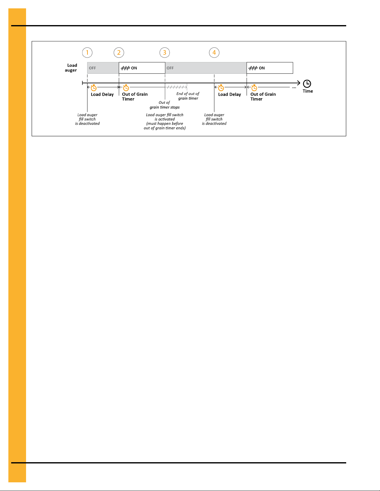
Chapter 6: The Wet Grain
Figure 6-1 The loading sequence in auto mode
Ensuring Dryer Shutdowns When Supply Is Out of Grain
To have the dryer stop when the wet grain storage bin empties, you can increase the out of grain timer if it
elapses before the dryer is full, or decrease it if the load auger keeps turning long after the wet grain
supply has been depleted.
Before You Begin
Make sure that the Load Auger switch on the control panel is in the Auto position. For information on the
out of grain timer’s role in the automatic loading sequence, see The Loading Process, page 53. The out of
grain timer is only active in auto mode and if the load auger is turning.
What You Should Know
The purpose of the out of grain timer is to stop the dryer when the wet grain storage bin is out of grain.
During the loading process, the out of grain timer begins once the load auger starts to turn in auto mode,
and resets to its default setting once the dryer is full. If the timer elapses, the dryer assumes that the
supply of wet grain is depleted and an out of grain shutdown occurs. Ideally, when the wet grain supply is
depleted, the out of grain timer elapses before dryer’s grain level drops below the upper edge of the grain
column. If this occurs, the dryer no longer detects airflow and a shutdown message is displayed onscreen.
Consider the following factors when setting the out of grain timer:
• The load delay setting
The out of grain timer starts once the load delay ends and the load auger starts to turn.
• The dryer’s unload speed
The speed that the dry grain is unloaded determines the time it takes to make room in the dryer wet
bin, which in turn, determines when the load delay starts.
• The speed that the loading mechanism fills the dryer wet bin
A fast speed requires a shorter timer setting. A slow speed requires a longer timer setting, so that the
dryer does not stop before the dryer wet bin is full.
To set the out of grain timer:
1. From the menu pane, click Load→Out of Grain Timer.
2. Set the following parameter:
54 PNEG-1851 Vision N2
Page 55

Chapter 6: The Wet Grain
Out of Grain Timer — The timer that starts once the load auger begins to turn and stops when the
dryer wet bin is full. If it elapses, a shutdown message alerts you that the wet grain storage bin supplying the dryer is empty. The Load Auger switch must be in the Auto position for the out of grain
timer to work.
NOTE: The Remaining field displays a countdown of the set delay or timer. Click it to interrupt the
countdown and enter a new value.
Tip
An out of grain timer setting that is too short causes the dryer to stop before the dryer wet bin fills up; a setting that is too long causes the load auger to keep turning long after the wet grain supply has been
depleted. If the default setting is inappropriate, set the out of grain timer to the maximum time it takes for
the loading mechanism to refill your dryer wet bin plus two to five minutes.
Minimizing Load Auger Startups
To minimize the number of times that the load auger starts, you can increase the load delay if the loading
mechanism starts more than once every two minutes, or decrease it if pressure-related shutdowns occur.
Before You Begin
Make sure that the Load Auger switch on the control panel is in the Auto. For information on the load
delay’s role in the automatic loading sequence, see The Loading Process, page 53. The load delay is only
active in auto mode.
What You Should Know
A load delay that is too short causes the loading mechanism to start and stop frequently. Because frequent
startups can shorten the life of the loading equipment’s electric motors, they should be avoided. On the
other hand, a load delay that is too long can cause low air pressure shutdowns to occur, as a result of the
grain level dropping below the top of the plenum chamber.
Consider the following factors when setting the load delay:
• The speed that the loading mechanism fills the dryer wet bin
A fast speed requires a longer delay to avoid frequent startups. A slow speed requires a shorter
delay to avoid pressure-related shutdowns.
• The dryer’s unload speed
The speed that dry grain is unloaded determines the time it takes to make room in the dryer wet bin.
The load delay starts once space in the dryer wet bin is detected.
To set the load delay:
1. From the menu pane, click System→Load (Advanced)→Load Delay.
2. Set the following parameter:
Load Delay — The time from when the dryer detects available space in the dryer wet bin (that is,
when the level of wet grain drops below the load auger fill switch) to when the loading mechanism is
activated. The Load Auger switch must be in the Auto position for the load delay to work.
NOTE: The Remaining field displays a countdown of the set delay or timer. Click it to interrupt the
countdown and enter a new value.
PNEG-1851 Vision N2
55
Page 56

Chapter 6: The Wet Grain
Tip
Start with the default setting and adjust according to how fast the loading mechanism fills your dryer wet
bin. As the dryer unloads dry grain, an appropriately set load delay ends before the level of wet grain drops
below the top of the plenum chamber.
Validating Incoming Moisture and Temperature Readings
Using a reliable grain testing device, you can validate the incoming moisture and temperature each time a
batch of grain is loaded to ensure that onscreen wet sensor readings are accurate.
Always use extreme caution when working around augers and auxiliary conveyors
CAUTION
To validate wet sensor readings:
1. Obtain a sample of the wet grain before a batch is loaded into the dryer wet bin.
2. Using a reliable grain testing device, measure the sample’s moisture content and temperature and
note the results.
IMPORTANT: When testing your grain, be sure to use a reliable, well-calibrated grain testing device
because they can start automatically.
that you are familiar with. If you are using a portable tester, always make sure that its
battery is charged prior to testing because an uncharged battery can cause inaccurate
readings. Always refer to the grain tester’s documentation for details.
3. Repeat steps 1 and 2 at least three times and average the results.
4. Compare your averaged results with those displayed onscreen. If necessary, adjust as follows:
a. From the menu pane, click Load→Wet Sensor Calibration.
b. Set the following parameters:
Incoming Grain Moisture — The wet grain’s actual moisture level (%).
Incoming Grain Temperature — The wet grain’s actual temperature (°F; °C)
Once measured, the actual average moisture of the wet grain is 27%, yet the value displayed
onscreen is 25%. Enter 27 to maintain consistency between readings.
NOTE: During the drying phase, make sure to validate the wet grain’s moisture and temperature at least
once a day.
56 PNEG-1851 Vision N2
Page 57

7 The Continuous Flow Drying
Process
Topics Covered in this Chapter
▪ Drying Grain in Continuous Flow
▪ Setting the 1-Speed Temperature Scheme in Continuous Flow
▪ Setting the 2-Speed Temperature Scheme in Continuous Flow
▪ Setting the 5-Speed Temperature Scheme in Continuous Flow
▪ Setting the 5-Speed Moisture Scheme in Continuous Flow
Drying Grain in Continuous Flow
To dry grain in continuous flow, you can choose a control scheme that uses either the grain’s temperature
or its moisture content to determine the metering roll speed.
Before You Begin
• Make sure to set the timers and delays (see Setting the Dryer’s Timers and Delays, page 30).
• Make sure to obtain the desired outgoing moisture level with the dryer unloading grain in manual
mode (Unload Auger switch to On) before switching to auto mode. To validate the moisture levels of
the dry grain, see Validating Outgoing Moisture And Temperature Readings, page 71.
• Decide whether to dry grain in full-heat or dry and cool operation. Once decided, set the switches on
the control panel as follows:
— In full-heat, place all Fan and Heater switches to On or Auto. In continuous flow drying, there is
no difference in placing the fan and heater switches in the On or Auto positions.
— In dry and cool, place all Fan switches to On or Auto, and place the bottom heater (where cooling
takes place) to Off.
Tip
In continuous flow drying, you can only use dry and cool if your dryer is equipped with two or more fans
and heaters.
What You Should Know
Full-heat allows you to discharge uncooled, hot grain whose moisture content is above its target, and then
manage the grain cooling process outside the confines of the dryer. Conversely, dry and cool allows you to
completely dry and cool the grain within the dryer and, in doing so, unload dry grain that is relatively close
to its target moisture content for storing. For more information on these drying operations, see Grain
Drying: Full-Heat or Dry and Cool, page 80.
To dry grain in continuous flow:
1. If the dryer is running, press Stop on the control panel.
PNEG-1851 Vision N2
57
Page 58

Chapter 7: The Continuous Flow Drying Process
IMPORTANT: To stop the dryer when connected remotely, click Stop Dryer from the main menu.
However, once stopped, you cannot restart it remotely. The dryer can only be
restarted on-site.
2. From the menu pane, click Control→Moisture Control Mode.
3. Select Continuous Flow.
4. Select one of the following control schemes:
1-Speed Temperature — The control scheme that allows you to set one metering roll speed and the
grain temperature setpoint. If the grain temperature is equal to, or rises 1°F (0.56°C) above its setpoint, the metering rolls turn at the set speed setting; 1°F (0.56°C) below the setpoint, the metering
rolls automatically stop turning.
2-Speed Temperature — The control scheme that allows you to set a low and high metering roll
speed and the grain temperature setpoint to control your dryer’s unload rate. If the grain temperature
rises 1°F (0.56°C) above its setpoint, the metering rolls turn at the high speed setting; 1°F (0.56°C)
below the setpoint, the low speed setting is used.
5-Speed Temperature — The control scheme that allows you to set one reference metering roll
speed, two temperature offsets, two speed offsets, and a grain temperature setpoint. As the grain
temperature rises or drops, the metering roll speed increases or decreases, respectively, according
to the preset parameters.
5-Speed Moisture — The control scheme that allows you to set one reference metering roll speed,
two moisture offsets, two speed offsets, and a dry grain moisture setpoint. As the grain moisture rises
or drops, the metering roll speed decreases or increases, respectively, according to the preset
parameters.
5. Set the drying parameters for your chosen control scheme:
• To set parameters for the 1-speed temperature control scheme, see Setting the 1-Speed Tem-
perature Scheme in Continuous Flow, page 58.
• To set parameters for the 2-speed temperature control scheme, see Setting the 2-Speed Tem-
perature Scheme in Continuous Flow, page 59.
• To set parameters for the 5-speed temperature control scheme, see Setting the 5-Speed Tem-
perature Scheme in Continuous Flow, page 60.
• To set parameters for the 5-Speed moisture control scheme, see Setting the 5-Speed Moisture
Scheme in Continuous Flow, page 61.
6. Configure the plenum temperature setpoints, see Setting the Plenum Temperature Range, page 35.
7. On the control panel, place the Load Auger and Unload Auger switches to Auto.
8. Press Start on the control panel.
Setting the 1-Speed Temperature Scheme in Continuous Flow
To have the metering rolls turn only when the set grain temperature is attained, you can select the 1-speed
temperature control scheme. Depending on the grain temperature, the metering rolls either turn or do not.
Before You Begin
Make sure to select the 1-Speed Temperature control scheme in the Moisture Control Mode window (see
Drying Grain in Continuous Flow, page 57 for details).
58 PNEG-1851 Vision N2
Page 59

Chapter 7: The Continuous Flow Drying Process
To set the 1-speed temperature scheme in continuous flow:
1. If the dryer is running, press Stop on the control panel.
IMPORTANT: To stop the dryer when connected remotely, click Stop Dryer from the main menu.
However, once stopped, you cannot restart it remotely. The dryer can only be
restarted on-site.
2. From the menu pane, click Control→Moisture Control Settings.
3. Set the following parameters:
Unload Speeds Entered in — The units of measure (bushels or metric tons per hour, or metering
roll speed %) that the unload speed value is entered in.
NOTE: The units of measure selection (bushels or metric tons per hour) that is displayed in this field
is dependent on the chosen system of measurement (System→Preferences→Units of
Measure).
Grain setpoint — The grain’s target temperature value. This setpoint is the reference parameter that
is used to determine your dryer’s unload rate.
Speed — The desired metering roll speed used to obtain the target grain temperature. If the grain
temperature is equal to, or rises 1°F (0.56°C) above its setpoint, the metering rolls turn at this speed
setting; 1°F (0.56°C) below the setpoint, the metering rolls automatically stop turning.
Let’s assume that you enter a grain temperature setpoint of 105°F and a speed setting of 300 Bph. If the
grain temperature is equal to or greater than 105°F, the metering rolls turn at 300 Bph. If the grain temperature drops to 104°F, the metering rolls stop turning.
After You Finish
Now that the control scheme is set, complete the procedure on drying grain in continuous flow mode (see
Drying Grain in Continuous Flow, page 57).
Setting the 2-Speed Temperature Scheme in Continuous Flow
To achieve the target moisture content using the grain temperature and two absolute metering rolls
speeds, you can select the 2-speed temperature control scheme as a precursor to the more comprehensive 5-speed schemes.
Before You Begin
Make sure to select the 2-Speed Temperature control scheme in the Moisture Control Mode window (see
Drying Grain in Continuous Flow, page 57 for details).
To set the 2-speed temperature scheme in continuous flow:
1. If the dryer is running, press Stop on the control panel.
IMPORTANT: To stop the dryer when connected remotely, click Stop Dryer from the main menu.
However, once stopped, you cannot restart it remotely. The dryer can only be
restarted on-site.
2. From the menu pane, click Control→Moisture Control Settings.
3. Set the following parameters:
Unload Speeds Entered in — The units of measure (bushels or metric tons per hour, or metering
roll speed %) that the unload speed values are entered in.
PNEG-1851 Vision N2 59
Page 60

Chapter 7: The Continuous Flow Drying Process
NOTE: The units of measure selection (bushels or metric tons per hour) that is displayed in this field
is dependent on the chosen system of measurement (System→Preferences→Units of
Measure).
Grain setpoint — The grain’s target temperature value. This setpoint is the reference parameter that
is used to determine your dryer’s unload rate.
High Speed — The high setpoint for the metering roll speed. If the grain temperature rises 1°F (0.56°
C) above its setpoint, the metering rolls turn at this speed setting.
Low Speed — The low setpoint for the metering roll speed. If the grain temperature drops 1°F (0.56°
C) below the setpoint, the metering rolls turn at this speed setting.
Let’s assume that you enter a grain temperature setpoint of 105°F, a high speed setting of 550 Bph, and a
low speed setting of 300 Bph. If the grain temperature rises to 106°F, the metering rolls turn at 550 Bph. If
the grain temperature drops to 104°F, the metering roll speed decreases to 300 Bph.
After You Finish
Now that the control scheme is set, complete the procedure on drying grain in continuous flow mode (see
Drying Grain in Continuous Flow, page 57).
Setting the 5-Speed Temperature Scheme in Continuous Flow
To regulate the grain temperature within the dryer by automatically switching between five different metering roll speeds, you can select the 5-speed temperature scheme when the wet grain’s moisture varies
considerably across the grain spread.
Before You Begin
Make sure to select the 5-Speed Temperature control scheme in the Moisture Control Mode window (see
Drying Grain in Continuous Flow, page 57 for details).
What You Should Know
Considering that grain temperature is constantly monitored inside the drying chamber, the metering roll
speed quickly adjusts to sudden fluctuations in the grain’s temperature level. As a result, the 5-speed temperature control scheme is suitable to use when operating in either full-heat or dry and cool.
To set the 5-speed temperature scheme in continuous flow:
1. If the dryer is running, press Stop on the control panel.
IMPORTANT: To stop the dryer when connected remotely, click Stop Dryer from the main menu.
However, once stopped, you cannot restart it remotely. The dryer can only be
restarted on-site.
2. From the menu pane, click Control→Moisture Control Settings.
3. Set the following parameters:
Unload Speeds Entered in — The units of measure (bushels or metric tons per hour, or metering
roll speed %) that the unload speed values are entered in.
NOTE: The units of measure selection (bushels or metric tons per hour) that is displayed in this field
is dependent on the chosen system of measurement (System→Preferences→Units of
Measure).
Reference Temperature — The grain’s target temperature value. This setpoint is the reference
parameter that is used to determine your dryer’s unload rate.
60 PNEG-1851 Vision N2
Page 61

Chapter 7: The Continuous Flow Drying Process
Inner Temperature Offset — The small temperature offset, used to obtain the pair of temperature
values that are closest to the reference temperature. One value is equal to reference temperature
minus this offset, whereas the other is equal to the reference temperature plus this offset.
Outer Temperature Offset — The large temperature offset, used to obtain the pair of temperature
values that are furthest from the reference temperature. One value is equal to reference temperature
minus this offset, whereas the other is equal to the reference temperature plus this offset.
Reference Speed — The metering roll’s setpoint (or reference) speed. This is the only true speed
parameter that you set; the others are offsets of this value.
Inner Speed Offset — The small speed offset, used to obtain the pair of speed values that are closest to the reference speed. One value is equal to reference speed minus this offset, whereas the
other is equal to the reference speed plus this offset.
Outer Speed Offset — The large speed offset, used to obtain the pair of speed values that are furthest from the reference speed. One value is equal to reference speed minus this offset, whereas the
other is equal to the reference speed plus this offset.
Let’s assume that you enter the following values: a reference temperature (T3) of 90°F; an inner temperature offset (T2, T4) of 1°F; an outer temperature offset (T1, T5) of 3°F; a reference speed (S3) of 50%; an
inner speed offset (S2, S4) of 5%; an outer speed offset (S1, S5) of 10%.
When the grain’s actual temperature reading is at 90°F (T3), the metering rolls turn at the reference speed
of 50% (S3). If the grain temperature rises to 91°F (T4), the metering roll speed increases to 55% (S4). If
the grain temperature continues to climb to 93°F (T5), the metering roll speed increases to 60% (S5), thus
allowing the grain to exit the drying chamber more rapidly. When the grain temperature drops back below
93°F, the metering roll speed starts to decrease back to the reference speed setpoint.
After You Finish
Now that the control scheme is set, complete the procedure on drying grain in continuous flow mode (see
Drying Grain in Continuous Flow, page 57).
Setting the 5-Speed Moisture Scheme in Continuous Flow
To regulate the grain moisture within the dryer by automatically switching between five different metering
roll speeds, you can select the 5-speed moisture scheme when the wet grain’s moisture varies considerably across the grain spread.
Before You Begin
Make sure to select the 5-Speed Moisture control scheme in the Moisture Control Mode window (see
Drying Grain in Continuous Flow, page 57 for details).
What You Should Know
It is recommended to use the 5-speed moisture control scheme if you are operating in full-heat and the
moisture content of the incoming wet grain varies by three percentage points or more across the grain
spread. Due to the inherent delays between drying, cooling, and unloading grain in the dry and cool operation, and that moisture levels are only monitored at the unload section, this control scheme is not recommended when operating in dry and cool.
To set the 5-speed moisture control scheme in continuous flow:
1. If the dryer is running, press Stop on the control panel.
PNEG-1851 Vision N2 61
Page 62

Chapter 7: The Continuous Flow Drying Process
IMPORTANT: To stop the dryer when connected remotely, click Stop Dryer from the main menu.
However, once stopped, you cannot restart it remotely. The dryer can only be
restarted on-site.
2. From the menu pane, click Control→Moisture Control Settings.
3. Set the following parameters:
Unload Speeds Entered in — The units of measure (bushels or metric tons per hour, or metering
roll speed %) that the unload speed values are entered in.
NOTE: The units of measure selection (bushels or metric tons per hour) that is displayed in this field
is dependent on the chosen system of measurement (System→Preferences→Units of
Measure).
Reference Moisture — The grain’s target moisture value. This setpoint is the reference parameter
that is used to determine your dryer’s unload rate.
Inner Moisture Offset — The large moisture offset, used to obtain the pair of moisture values that
are furthest from the reference moisture. One value is equal to reference moisture minus this offset,
whereas the other is equal to the reference moisture plus this offset.
Outer Moisture Offset — The large moisture offset, used to obtain the pair of moisture values that
are furthest from the reference moisture. One value is equal to reference moisture minus this offset,
whereas the other is equal to the reference moisture plus this offset.
Reference Speed — The metering roll’s setpoint (or reference) speed. This is the only true speed
parameter that you set; the others are offsets of this value.
Inner Speed Offset — The small speed offset, used to obtain the pair of speed values that are closest to the reference speed. One value is equal to reference speed minus this offset, whereas the
other is equal to the reference speed plus this offset.
Outer Speed Offset — The large speed offset, used to obtain the pair of speed values that are furthest from the reference speed. One value is equal to reference speed minus this offset, whereas the
other is equal to the reference speed plus this offset.
Let’s assume that you enter the following values: a reference moisture level (M3) of 15%; an inner moisture
offset (M2, M4) of 1%; an outer moisture offset (M1, M5) of 3%; a reference speed (S3) of 50%; an inner
speed offset (S2, S4) of 5%; an outer speed offset (S1, S5) of 10%.
When the grain’s actual moisture content is at 15% (M3), the metering rolls turn at the reference speed of
50% (S3). If the moisture content rises to 16% (M4), the metering roll speed decreases to 45% (S2). If the
grain’s moisture continues to climb to 18% (M5), the metering roll speed decreases to 40% (S1), thus
allowing the grain to remain in the drying chamber longer. When the grain’s moisture content drops back
below 18%, the metering roll speed starts to increase back to the reference speed setpoint.
After You Finish
Now that the control scheme is set, complete the procedure on drying grain in continuous flow mode (see
Drying Grain in Continuous Flow, page 57).
62 PNEG-1851 Vision N2
Page 63

8 The Staged Batch Drying Process
Topics Covered in this Chapter
▪ Drying Grain in Staged Batch
▪ Setting the Time Scheme in Staged Batch
▪ Setting the Temperature Scheme in Staged Batch
▪ Setting the Time and Temperature Scheme in Staged Batch
▪ Setting the Dual-Setpoint Time Scheme in Staged Batch
▪ Setting the Dual-Setpoint Temperature Scheme in Staged Batch
Drying Grain in Staged Batch
To dry grain in batches, you can choose a control scheme that notifies you when grain is ready to move to
the cooling phase (in dry and cool operation) or unloading phase.
Before You Begin
Make sure to set the timers and delays (see Setting the Dryer’s Timers and Delays, page 30).
To dry grain in staged batch:
1. If the dryer is running, press Stop on the control panel. To stop the dryer when connected remotely,
click Stop Dryer from the main menu. However, once stopped, you cannot restart it remotely. The
dryer can only be restarted on-site.
IMPORTANT: To simultaneously reset all staged batch timers (drying, cooling, cool-down, and
unloading timers) to their set values, press and hold Stop on the control panel for five
seconds. This reset can only be performed on-site, not through GSI’s remote web
application.
2. From the menu pane, click Control→Moisture Control Mode.
3. Select Staged Batch.
4. Select one of the following control schemes:
Time — The control scheme that uses a timer to establish the duration of the drying phase.
Temperature — The control scheme that uses the grain temperature setpoint to establish the dura-
tion of the drying phase.
Time and Temperature — The control scheme that uses the drying time and grain temperature setpoint to establish the duration of the drying phase. The drying phase ends only once the drying time
has elapsed and the grain setpoint is reached.
Dual-Setpoint Time — The control scheme that exposes grain to two different drying temperatures.
The plenum temperature switches from one setpoint to the other after a predetermined time.
Dual-Setpoint Temperature — The control scheme that exposes grain to two different drying temperatures. The plenum temperature switches from one setpoint to the other once the grain temperature reaches a predetermined setpoint.
PNEG-1851 Vision N2 63
Page 64

Chapter 8: The Staged Batch Drying Process
5. Set the drying parameters for your chosen control scheme:
• To set parameters for the time scheme, see Setting the Time Scheme in Staged Batch, page
64.
To set parameters for the temperature scheme, see Setting the Temperature Scheme in Staged
Batch, page 65.
• To set parameters for the time and temperature scheme, see Setting the Time and Temperature
Scheme in Staged Batch, page 66.
• To set parameters for the dual-setpoint time scheme, see Setting the Dual-Setpoint Time
Scheme in Staged Batch, page 67.
To set parameters for the dual-setpoint temperature scheme, see Setting the Dual-Setpoint
Temperature Scheme in Staged Batch, page 68.
NOTE: See appendix B, page 87 for illustrative descriptions of all the control schemes in staged
batch.
6. Configure the plenum temperature setpoints, see Setting the Plenum Temperature Range, page 35.
7. On the control panel, place the Fan, Heater, Load Auger, and Unload Auger switches to Auto.
8. Press Start on the control panel.
Tip
To optimize the drying process in the full-heat operation, you can let the dryer run while dry grain unloads,
by placing the Heater switches to the On position instead of Auto.
Tip
To optimize the cooling process in the dry and cool operation, you can let the cooling fans run at the
bottom of the dryer while dry grain unloads, by placing the respective Fan switches to On instead of Auto.
Setting the Time Scheme in Staged Batch
To expose the grain to heat for a predefined length of time, you can use the time control scheme when running in staged batch.
Before You Begin
Make sure to select the Time control scheme in the Moisture Control Mode window (see Drying Grain in
Staged Batch, page 63 for details).
To set the time control scheme in staged batch:
1. If the dryer is running, press Stop on the control panel.
IMPORTANT: To stop the dryer when connected remotely, click Stop Dryer from the main menu.
However, once stopped, you cannot restart it remotely. The dryer can only be
restarted on-site.
2. From the menu pane, click Control→Moisture Control Settings.
3. Set the following parameter:
Drying Time — The timer that must elapse to end the drying phase.
Let’s assume that you enter the following values:
64 PNEG-1851 Vision N2
Page 65

Chapter 8: The Staged Batch Drying Process
• Drying time of 35 minutes
• Cooling timer of 18 minutes
• Unload timer of 10 minutes
• Plenum setpoints of 180°F (for ease of explanation, let’s assume that all plenums use the same
setpoint)
The drying phase starts when the load auger fill switch is activated. During this phase, all fans and heaters
are on so that the plenums can reach a temperature of 180°F. The heaters stop after 35 minutes of operation. Once the heaters are off, the fans continue running for another 18 minutes to cool the hot grain and
then stop. Once the cooling phase ends, the unload auger runs for 10 minutes to discharge the dry and
cool grain into an external storage bin.
Figure 8-1 Sequence of operation for the time control scheme in staged batch
After You Finish
Now that the control scheme is set, complete the procedure on drying grain in staged batch mode (see
Drying Grain in Staged Batch, page 63).
Setting the Temperature Scheme in Staged Batch
To end the drying phase when the grain temperature reaches a predefined value, you can use the temperature control scheme when running in staged batch.
Before You Begin
Make sure to select the Temperature control scheme in the Moisture Control Mode window (see Drying
Grain in Staged Batch, page 63 for details).
To set the temperature control scheme in staged batch:
1. If the dryer is running, press Stop on the control panel.
IMPORTANT: To stop the dryer when connected remotely, click Stop Dryer from the main menu.
However, once stopped, you cannot restart it remotely. The dryer can only be
restarted on-site.
2. From the menu pane, click Control→Moisture Control Settings.
3. Set the following parameter:
Grain Setpoint — The grain temperature that must be reached to end the drying phase.
Let’s assume that you enter the following values:
• Grain temperature setpoint of 90°F
• Cooling timer of 18 minutes
PNEG-1851 Vision N2 65
Page 66

Chapter 8: The Staged Batch Drying Process
• Unload timer of 10 minutes
• Plenum setpoints of 180°F (for ease of explanation, this example assumes that all plenums use the
same setpoint)
The drying phase starts when the load auger fill switch is activated. During that phase, all fans and heaters
are on so that the plenums can reach a temperature of 180°F. The heaters stop once the grain temperature
reaches 90°F. Once the heaters are off, the fans continue running for another 18 minutes to cool the hot
grain and then stop. Once the cooling phase ends, the unload auger runs for 10 minutes to discharge the
dry and cool grain into an external storage bin.
Figure 8-2 Sequence of operation for the temperature control scheme in staged batch
After You Finish
Now that the control scheme is set, complete the procedure on drying grain in staged batch mode (see
Drying Grain in Staged Batch, page 63).
Setting the Time and Temperature Scheme in Staged Batch
To end the drying phase when the grain temperature reaches a specific value and a predefined length of
time elapses, you can use the time and temperature control scheme when running in staged batch.
Before You Begin
Make sure to select the Time and Temperature control scheme in the Moisture Control Mode window
(see Drying Grain in Staged Batch, page 63 for details).
To set the time and temperature control scheme in staged batch:
1. If the dryer is running, press Stop on the control panel.
IMPORTANT: To stop the dryer when connected remotely, click Stop Dryer from the main menu.
However, once stopped, you cannot restart it remotely. The dryer can only be
restarted on-site.
2. From the menu pane, click Control→Moisture Control Settings.
3. Set the following parameters:
Drying Time — The timer that must elapse to end the drying phase.
Grain Setpoint — The grain temperature that must be reached to end the drying phase.
The drying phase ends when the drying timer elapses and the grain setpoint is reached.
Let’s assume that you enter the following values:
• Grain temperature setpoint of 90°F
• Drying time of 35 minutes
66 PNEG-1851 Vision N2
Page 67

Chapter 8: The Staged Batch Drying Process
• Cooling timer of 18 minutes
• Unload timer of 10 minutes
• Plenum setpoints of 180°F (for ease of explanation, this example assumes that all plenums use the
same setpoint)
The drying phase starts when the load auger fill switch is activated. During this phase, all fans and heaters
are on so that the plenums can reach a temperature of 180°F. The heaters stop running when the grain
temperature reaches 90°F and 35 minutes have elapsed. Once the heaters are off, the fans continue running for another 18 minutes to cool the hot grain and then stop. Once the cooling phase ends, the unload
auger runs for 10 minutes to discharge the dry and cool grain into an external storage bin.
Figure 8-3 Sequence of operation for the time and temperature control scheme in staged batch
After You Finish
Now that the control scheme is set, complete the procedure on drying grain in staged batch mode (see
Drying Grain in Staged Batch, page 63).
Setting the Dual-Setpoint Time Scheme in Staged Batch
To expose the grain to two different drying temperatures, and switch from one temperature value to the
other once a predefined length of time elapses, you can use the dual-setpoint time control scheme when
running in staged batch.
Before You Begin
Make sure to select the Dual-Setpoint Time control scheme in the Moisture Control Mode window (see
Drying Grain in Staged Batch, page 63 for details).
To set the dual-setpoint time control scheme in staged batch:
1. If the dryer is running, press Stop on the control panel.
IMPORTANT: To stop the dryer when connected remotely, click Stop Dryer from the main menu.
However, once stopped, you cannot restart it remotely. The dryer can only be
restarted on-site.
2. From the menu pane, click Control→Moisture Control Settings.
3. Set the following parameters:
Drying Time 1 — The timer that must elapse to make the plenums use the second group of temperature setpoints.
Drying Time 2 — The timer that must elapse to end the drying phase.
Let’s assume that you enter the following values:
PNEG-1851 Vision N2 67
Page 68

Chapter 8: The Staged Batch Drying Process
• Drying time 1 of 25 minutes
• Drying time 2 of 12 minutes
• Cooling timer of 18 minutes
• Unload timer of 10 minutes
• Plenum setpoints 1 of 220°F (for ease of explanation, this example assumes that all plenums use the
same setpoint)
• Plenum setpoints 2 of 170°F (for ease of explanation, this example assumes that all plenums use the
same setpoint)
The drying phase starts when the load auger fill switch is activated. During drying time 1, all fans and heaters are on so that the plenums can reach a temperature of 220°F. After 25 minutes of operation, the
second drying timer starts and the heat intensity decreases so that the plenum temperature can drop to
170°F. This new plenum temperature is maintained for 12 minutes and then the heaters stop.
Once heaters are off, the fans continue running for another 18 minutes to cool the hot grain and then stop.
Once the cooling phase ends, the unload auger runs for 10 minutes to discharge the dry and cool grain
into an external storage bin.
Figure 8-4 Sequence of operation for the dual-setpoint time control scheme in staged batch
After You Finish
Now that the control scheme is set, complete the procedure on drying grain in staged batch mode (see
Drying Grain in Staged Batch, page 63).
Setting the Dual-Setpoint Temperature Scheme in Staged Batch
To expose the grain to two different drying temperatures, and switch from one temperature value to the
other once the grain reaches a predefined setpoint, you can use the dual-setpoint temperature control
scheme when running in staged batch.
Before You Begin
Make sure to select the Dual-Setpoint Temperature control scheme in the Moisture Control Mode
window (see Drying Grain in Staged Batch, page 63 for details).
To set the dual-setpoint temperature scheme in staged batch:
1. From the menu pane, click Control→Moisture Control Settings.
2. If the dryer is running, press Stop on the control panel.
IMPORTANT: To stop the dryer when connected remotely, click Stop Dryer from the main menu.
However, once stopped, you cannot restart it remotely. The dryer can only be
restarted on-site.
3. Set the following parameters:
68 PNEG-1851 Vision N2
Page 69

Chapter 8: The Staged Batch Drying Process
Grain Setpoint 1 — The grain temperature that must be reached to make the plenums use the
second group of temperature setpoints.
Grain Setpoint 2 — The grain temperature that must be reached to end the drying phase.
Let’s assume that you enter the following values:
• Grain setpoint 1 of 85°F
• Grain setpoint 2 of 90°F
• Cooling timer of 18 minutes
• Unload timer of 10 minutes
• Plenum setpoints 1 of 220°F (for ease of explanation, this example assumes that all plenums use the
same setpoint)
• Plenum setpoints 2 of 170°F (for ease of explanation, this example assumes that all plenums use the
same setpoint)
The drying phase starts when the load auger fill switch is activated. At the beginning of this phase, all fans
and heaters are on so that the plenums can reach a temperature of 220°F. Once the grain temperature
reaches 85°F, the heat intensity decreases so that the plenum temperature can drop to 170°F. This new
plenum temperature is maintained until the grain temperature reaches 90°F and then heaters stop.
Once the heaters are off, the fans continue running for another 18 minutes to cool the hot grain and then
stop. Once the cooling phase ends, the unload auger runs for 10 minutes to discharge the dry and cool
grain into an external storage bin.
Figure 8-5 Sequence of operation for the dual-setpoint temperature control scheme in staged batch
After You Finish
Now that the control scheme is set, complete the procedure on drying grain in staged batch mode (see
Drying Grain in Staged Batch, page 63).
PNEG-1851 Vision N2 69
Page 70

NOTES
70 PNEG-1851 Vision N2
Page 71

9 The Dry Grain
Topics Covered in this Chapter
▪ Validating Outgoing Moisture And Temperature Readings
▪ Cleaning the Dry Sensor
▪ Setting the Value Range for the Unload Speed
▪ Adjusting Unload Speeds in Real Time
▪ Ensuring Accurate Unload Speed Rates
Validating Outgoing Moisture And Temperature Readings
Using a reliable grain testing device, you can validate the outgoing moisture and temperature at regular
intervals to ensure that onscreen dry sensor readings are accurate.
To validate dry sensor readings:
1. Obtain a sample of dry grain from the grain sampler.
Figure 9-1 The grain sampler, located next to the grain discharge box
2. Using a reliable grain testing device, measure the sample’s moisture content and temperature and
note the results.
IMPORTANT: When testing your grain, be sure to use a reliable, well-calibrated grain testing device
that you are familiar with. If you are using a portable tester, always make sure that its
battery is charged prior to testing because an uncharged battery can cause inaccurate
readings. Always refer to the grain tester’s documentation for details.
3. Repeat steps 1 and 2 at least three times and average the results.
4. Compare your averaged results with those displayed onscreen. If necessary, adjust as follows:
a. From the menu pane, click Unload→Dry Sensor Calibration.
b. Set the following parameter:
PNEG-1851 Vision N2 71
Page 72

Chapter 9: The Dry Grain
Outgoing Grain Moisture — The dry grain’s actual moisture level (%).
Outgoing Grain Temperature — The dry grain’s actual temperature (°F; °C)
Once measured, the actual average moisture of the dry grain is 15%, yet the value displayed
onscreen is 17%. Enter 15 to maintain consistency between readings.
IMPORTANT: During the unloading phase, make sure to validate the dry grain’s moisture and temperature
at least twice a day and make the necessary adjustments.
If grain is consistently discharging at a moisture content that is too high, increase the grain temperature
setpoint of the applicable control scheme. An increase of 5°F (2.78°C) removes one point of moisture.
Conversely, if grain is consistently discharging at a moisture content that is too low, decrease the grain
temperature setpoint of the applicable control scheme. A decrease of 5°F (2.78°C) adds one point of the
moisture.
Cleaning the Dry Sensor
To ensure that the dry sensor functions properly, you must check it daily and clean it once every 100 hours
of operation. Clean the dry sensor more often if the grain is too dirty.
To clean the dry sensor:
1. If the dryer is running, press Stop on the control panel, and then turn the Power switch to Off.
2. Place the safety disconnect switch in the Off position, and then turn off the dryer’s main power.
The main power that is present at the electrical cabinets turns off.
The Power switch controls dryer functions but does not control the power that is
CAUTION
3. From the rear of the dryer, locate the dry sensor housing and the sensor cover. The dry sensor is
mounted to the back of the sensor cover.
Figure 9-2 The dry sensor cover, behind which is mounted the dry sensor
present at the various electrical cabinets. Turn off the main electrical disconnect
switch to shut off power to the dryer and all electrical cabinets.
4. Unlatch the sensor cover to access the inside of the dry sensor housing.
72 PNEG-1851 Vision N2
Page 73

Chapter 9: The Dry Grain
5. Clean the inside of the housing thoroughly.
6. Position the dry sensor back into place and secure the sensor cover.
Setting the Value Range for the Unload Speed
Defining an allowable value range ensures that the unload speed is always set within a minimum and maximum limits. Once set, you can modify this range if the established values are either insufficient or
excessive.
To set the value range for the unload speed:
1. From the menu pane, click System→Unload (Advanced)→Min/Max Unload Speeds.
2. Set the following parameters:
Unload Speeds Entered in — The units of measure (bushels or metric tons per hour, or metering
roll speed %) that the minimum and maximum unload speeds are entered in.
NOTE: The units of measure selection (bushels or metric tons per hour) that is displayed in this field
is dependent on the chosen system of measurement (System→Preferences→Units of
Measure).
Maximum Speed — The metering roll speed’s upper limit. Unload speeds cannot exceed this value.
Minimum Speed — The metering roll speed’s lower limit. Unload speeds cannot be less than this
value.
IMPORTANT: The metering roll speed cannot exceed the maximum setpoint or drop below the minimum
setpoint, regardless of whether you manually select an unload speed that lies beyond
these limits, or if the selected control scheme automatically attempts to do so. The minimum and maximum speed setpoints are fixed limits that cannot be violated.
Let’s assume that the maximum speed of the metering rolls is set to 600 bph, but according to the specifications of the unload auger’s motor, this speed setting is too high for the unload auger. When the unload
speed is set to 600 bph, the unload auger jams because it is not able to keep up with the metering rolls. In
this case, reduce the maximum and minimum speeds accordingly, thus preventing you from entering an
unload speed that is too high.
Adjusting Unload Speeds in Real Time
Once you have selected a drying mode and set the parameters for your chosen control scheme, you can
adjust the unload speed in real time without modifying or effecting the original values.
Before You Begin
Make sure to set the parameter settings for your chosen control scheme. For a list of the available control
schemes in continuous flow, see Drying Grain in Continuous Flow, page 57; for staged batch, see Drying
Grain in Staged Batch, page 63.
What You Should Know
The unload speed parameters can be entered in two places: in the Moisture Control Settings window of
the drying mode’s respective control scheme (in continuous flow), or in the Unload Speeds window once
the desired control scheme has been selected. For example, if 2-Speed Temperature is selected in the
Moisture Control Mode window, the Unload Speeds window allows you to simultaneously adjust the high
and low speed settings of this control scheme.
PNEG-1851 Vision N2 73
Page 74

Chapter 9: The Dry Grain
To adjust unload speeds in real time:
1. From the menu pane, click Unload→Unload Speeds.
2. Set the following parameter:
Unload Speeds Entered in — The units of measure (bushels or metric tons per hour, or metering
roll speed %) that the unload speed value is entered in.
3. Adjust the unload speed according to the following conditions:
a. If you are running the 1-speed temperature control scheme in continuous flow, set the following
parameters:
Adjusted Speed — In either the 1-speed temperature control scheme in continuous flow or any
of the control schemes in staged batch, the adjusted speed that the metering rolls turn at when
the Unload Auger switch is in the Auto position.
Incremental Adjustment — The incremental adjustment of the metering rolls’ actual speed in
auto mode.
Once entered, the speed value that appears in the moisture control settings of this control
scheme does not change.
b. If you are running the 2-speed temperature or 5-speed temperature control scheme in continuous
flow, click the following buttons:
Incremental Adjustment — The incremental adjustment of the metering rolls’ actual speed in
auto mode.
Once clicked, all speed values and their respective offsets increase or decrease simultaneously,
in single-digit increments.
NOTE: The Unload Speeds window is disabled when running the 5-speed moisture control
scheme in continuous flow.
c. If you are running any of the control schemes in staged batch, set the following parameters:
Adjusted Speed — In either the 1-speed temperature control scheme in continuous flow or any
of the control schemes in staged batch, the adjusted speed that the metering rolls turn at when
the Unload Auger switch is in the Auto position.
Incremental Adjustment — The incremental adjustment of the metering rolls’ actual speed in
auto mode.
The Actual Speed field displays the current speed of the metering rolls. This value is also displayed in the System Parameters pane in the main menu.
IMPORTANT: Unload speeds cannot be set lower or higher than the minimum and maximum limits,
respectively.
Ensuring Accurate Unload Speed Rates
To ensure that the displayed unload speed matches your dryer’s actual flow rate, you can perform a validation procedure that automatically adjusts your dryer’s unload speed based on measured values of
unloaded grain.
Before You Begin
Make sure to select a drying mode and corresponding control scheme, and enter all settings in the
scheme’s respective moisture control settings window.
74 PNEG-1851 Vision N2
Page 75

Chapter 9: The Dry Grain
What You Should Know
Over the course of numerous drying cycles and batches of grain, the unload speed automatically changes
to adapt to the moisture and temperature variations of the grain. Although validating the moisture content
of both the wet and dry grain is essential, you can also validate the grain’s actual flow rate to help optimize
unload speeds and minimize inefficient fluctuations.
Tip
It is recommended to validate the unload speed after replacing the main I/O board.
To validate the actual unload speed:
1. Measure the actual amount of dry grain that the dryer unloads over a minimum of a one-hour period
(seeValidating Outgoing Moisture And Temperature Readings, page 71 for details).
2. Compare the measured rate that you obtained in step 1, with the unload speed value that is displayed
in the main menu (see The Main Menu, page 19 to locate the unload speed value).
3. From the taskbar, click System→Unload (Advanced)→Unload Speed Calibration.
4. Set the following parameter:
Unload Speed Calibration — The adjustment factor (%) for the displayed metering roll speed. This
adjustment ensures that the calculated and actual grain flow rates are proportionate. A setting of
100% indicates that both rates are equivalent.
Tip
Prior to the initial drying cycle, set the adjustment factor for the unload speed to 100%.
Let’s assume that after manually measuring the actual amount of unloaded grain over a one-hour period,
you obtain a dry grain output value of 525 bushels, however, the metering roll speed value that is displayed
onscreen is 500 bph. Considering that the actual flow rate is 5% higher than the calculated value, enter
105% so that the dryer adjusts the unload speed accordingly.
PNEG-1851 Vision N2
75
Page 76

NOTES
76 PNEG-1851 Vision N2
Page 77

A Grain Drying Operations
Topics Covered in this Appendix
▪ Drying Grain: A Quick Startup Procedure
▪ Initial Settings for Full-Heat and Dry and Cool
▪ The Burner Modes
▪ Grain Drying: Full-Heat or Dry and Cool
Drying Grain: A Quick Startup Procedure
Once you are familiar with your dryer and the grain handling equipment, you can follow a quick-step
approach to quickly transition from powering on your dryer to drying grain in auto mode.
Before You Begin
• Make sure that all safety shields are securely in place.
• Make sure that the bottom closure panel doors for all plenums and all rear access doors are closed.
• Make sure that all personnel are clear of the grain drying and grain handling equipment.
For detailed information on powering on your dryer and drying grain during the initial run, see Powering On
the Dryer, page 27. For the startup settings for full-heat and dry and cool drying operations, see Initial Settings for Full-Heat and Dry and Cool, page 78).
To begin drying grain:
1. On the control panel, turn off all switches.
2. On the dryer’s main control box, turn on the safety disconnect switch.
3. Open all fuel supply valves except for the automatic shutoff valve.
4. On the control panel, turn on the Power switch, and then click the Software Start button.
5. Turn the Load Auger switch to On.
6. When the dryer is full of grain, turn the Load Auger switch to Auto.
7. Turn on all Fan and Heater switches.
8. Set all burners to 180°F (100°C).
9. Based on the moisture content of the wet grain, run the burners for the drying time indicated in the
startup settings for the respective drying operation.
Tip
If running dry and cool, turn off the bottom heater once the drying time elapses, and run the dryer for
an additional 10 minutes so that the grain can cool.
10.Turn the Unload Auger switch to On, and set the metering roll speed to the setting indicated in the
startup settings for the respective drying operation.
PNEG-1851 Vision N2
77
Page 78

Appendix A: Grain Drying Operations
11.Increase the plenum temperature to your normal operating temperature.
12.Continue unloading in manual mode for a minimum of five to seven minutes for each point of moisture you need to remove.
13.Turn the Unload Auger switch to Auto.
Initial Settings for Full-Heat and Dry and Cool
Once the wet grain’s moisture content has been measured during the initial run, you can set the drying
time and unload speed according to the drying operation’s respective table below.
For details on when to use these initial settings, see Drying Grain in the Initial Run, page 32.
Table A-1 Initial settings for the full-heat operation
Unload speed in manual mode
Initial
moisture
17% 16 630 990 990
18%
19% 26 390 810 990
20% 32 320 670 990
21% 37 270 570 860
22%
23% 47 210 450 680
24% 51 200 410 620
25% 54 180 390 590
26% 58 170 360 550
27% 62 160 340 510
28% 67 150 320 480
29%
30% 76 130 280 420
31% 81 120 260 390
32% 86 120 250 370
33% 91 110 230 350
34% 96 100 220 330
35% 100 100 210 320
Drying time
(min.)
21 480 990 990
42 240 510 770
72 140 300 450
One-module
dryer (bph)
Two-module
dryer (bph)
module dryer
Three-
(bph)
78 PNEG-1851 Vision N2
Page 79

Table A-2 Initial settings for the dry and cool operation
Unload speed in manual mode
Appendix A: Grain Drying Operations
Initial
moisture
17% 18 360 890 990
18%
19% 30 220 540 730
20% 35 190 460 620
21% 40 160 400 540
22% 45 140 360 480
23% 50 130 320 440
24% 55
25% 60 110 270 360
26% 65 100 250 330
27% 70 90 260 310
28% 75
29% 80 80 200 270
30% 85 80 190 260
31% 90 70 180 240
32% 95 70 170 230
33% 100 60 160 220
34% 105 60 150 210
35% 110 60 150 200
Drying time
(min.)
24 270 670 910
One-module
dryer (Bph)
120 290 400
90 210 290
Two-module
dryer (Bph)
module dryer
Three-
(Bph)
The Burner Modes
When heating the plenum, the burner modes help avoid high plenum temperatures and frequent fluctuations. The chosen burner mode is dependent on the grain type and outside temperature.
Establishing a uniform plenum temperature is important, as it is the air in the plenum that is eventually
released into the drying chamber to dry the grain. As a result, frequent fluctuations in the plenum’s temperature or temperature levels that are too high directly impact the quality of the grain. To help regulate the
temperature inside the plenum chamber, each available burner mode uses the plenum temperature setpoint and burner differential settings as reference parameters (see Setting the Plenum Temperature
Range, page 35). It is the sum or difference of these two parameters that determine whether the burner
operates in low fire or high fire, or in some instances, shuts off. The available burner modes are shown in
the table that follows.
PNEG-1851 Vision N2 79
Page 80

Appendix A: Grain Drying Operations
Table A-3 Description of the burner modes
Mode
High/low
On/off
Auto
Description
Starting on high fire, when the plenum temperature exceeds the plenum temperature setpoint plus
the burner differential setting, the burner switches to low fire. Similarly, when the plenum temperature drops below the plenum temperature setpoint minus the burner differential setting, the burner
switches back to high fire. High/low mode is the default setting.
Starting on high fire, when the plenum temperature exceeds the plenum temperature setpoint plus
the burner differential setting, the burner shuts off. Similarly, when the plenum temperature drops
below the plenum temperature setpoint minus the burner differential setting, the burner reignites
and switches back to high fire.
The burner operates in high/low mode until one of the two following scenarios occur: if the burner
remains in low fire for more than 60 seconds, or the plenum temperature exceeds the plenum temperature setpoint by 20°F (11.1°C) for more than 10 seconds, the burner automatically switches to
on/off mode.
Examples
• High/low: Let’s assume that you enter a plenum setpoint of 210°F and a burner differential value of
+/- 1°F. On high fire, when the plenum’s actual temperature reaches 211°F, the burner switches to
low fire. On low fire, when the plenum’s actual temperature drops to 209°F, the burner switches back
to high fire.
• On/off: Let’s assume that you enter a plenum setpoint of 210°F and a burner differential value of +/1°F. On high fire, when the plenum’s actual temperature reaches 211°F, the burner shuts off. With the
burner off, when the plenum’s actual temperature drops to 209°F, the burner reignites and switches
back to high fire.
• Auto: Let’s assume that you enter a plenum setpoint of 210°F and a burner differential value of +/- 1°
F. In auto mode, the burner operates in high/low mode until one of the following two scenarios forces
it to switch to on/off mode: (1) If the burner is in low fire and the plenum’s actual temperature remains
below 211°F for more than 60 seconds, the burner switches to on/off mode and high fire ignites; (2) If
the plenum’s actual temperature reaches 230°F, the burner switches to on/off mode and shuts off.
Tip
To ensure uniform drying between the front and rear of the dryer, the burners should switch between high
fire and low fire twice per minute, on average. Start with the default setting (high/low), and select another
mode if the plenum cannot reach its temperature setpoint, or if the burner is not switching between high
fire and low fire at least once per minute. To select a burner mode, click System→Dry (Advanced)→-
Burner Mode.
Grain Drying: Full-Heat or Dry and Cool
Regardless of the chosen drying mode (continuous flow or staged batch), you can choose to dry grain in
full-heat or dry and cool. These operations are not actual selections, but drying methods that are actuated
via the fan and heater switches.
Full-heat allows you to discharge uncooled, hot grain whose moisture content is above its target, and then
manage the grain cooling process outside the confines of the dryer. To operate your dryer in full-heat,
regardless of the mode, make sure that all Fan and Heater switches on the control panel are set to On.
Conversely, dry and cool allows you to completely dry and cool the grain within the dryer and, in doing so,
unload dry grain that is relatively close to its target moisture content for storing. To operate your dryer
using dry and cool in continuous flow mode, make sure that the bottom Fan switch is set to On and the
Heater switch is set to Off. In staged batch mode, the Fan and Heater switches must be set to Auto.
80 PNEG-1851 Vision N2
Page 81

Appendix A: Grain Drying Operations
To decide which drying operation is better suited to your needs, a good grasp of the benefits and shortcomings of each operation is required (see the following table). Furthermore, considering that the main difference between the two is in the physical location of where the grain cooling process takes place, a general
understanding of this important step in the grain drying process is also recommended (see A Glance at
Cooling Processes, page 82).
Table A-4 Advantages and disadvantages of the full-heat drying operation
Advantages Disadvantages
• Allows you to simply dry the grain and then transfer it to a dedicated bin for cooling. As a result,
the hot grain can be cooled at a slower rate,
thereby saving on energy costs and improving
grain quality.
• Increases drying capacity by allowing more bushels per hour to flow through the dryer.
• Increases dryer fuel efficiency as the grain is only
dried, not cooled and therefore spends less time
in the dryer. The hot grain can be transferred to
the cooling bin at a moisture content of 1% to 3%
above its target moisture level.
• Allows you to stage the drying process in a multifan configuration; that is, set higher drying temperatures in the top plenum and gradually lower
temperatures as you move towards the bottom of
the dryer. Staging the drying temperature is ideal
for wet grain that is very wet.
• Allows you to use slow cooling methods when
cooling the grain and, as a result, greatly benefit
grain quality (see A Glance at Cooling Processes,
page 82 for more information).
• Not recommended for all types of grain. Full-heat
is mostly used for drying corn.
• Leads to a higher risk of grain spoilage if the
grain is transferred to cooling bins at a moisture
content that is too high. Proper measuring of the
dry grain’s moisture content should be performed
regularly.
• Requires suitable grain handling equipment, a
logical layout of the handling system, and additional management time, when cooling in dedicated bins.
• Requires the additional cost and management
time associated with transferring hot grain from
the dryer to the cooling bins.
Table A-5 Advantages and disadvantages of the dry and cool drying operation
Advantages Disadvantages
• Can be used for all types of grain.
• Does not require the additional cost and management time associated with dedicated cooling bins,
because the grain is dried and cooled entirely
inside the dryer.
• Allows you to transfer dry grain directly to storage
bins, once the grain is dried and cooled to within
10° to 15° of the outside temperature. With corn,
this allows you to use storage bins with no aeration (in winter), if the corn is unloaded with a moisture content of 13%. At 15% moisture, minimal
aeration is required.
PNEG-1851 Vision N2 81
• Leads to higher fuel costs because the grain is
dried and then cooled.
• Decreases drying capacity because the grain
spends more time in the dryer, thus reducing
productivity.
• Overdrying of the grain is probable, thus resulting
in lower grain quality. Optional grain inverters
help eliminate the risk of overdrying.
• Leads to a higher risk of kernel damage when
grain is dried and then cooled inside a highspeed dryer. For certain types of grain, the rapid
transition from hot to cool air might increase the
risk of stress cracks and render the kernel brittle.
Page 82

Appendix A: Grain Drying Operations
A Glance at Cooling Processes
Cooling grain in dedicated cooling bins is a viable and cost-effective solution for most grain farmers, and
one that provides the most benefits in terms of grain quality.
The most common grain cooling processes are dryeration, in-storage (or bin) cooling, and combination
drying. The figure that follows illustrates these three cooling processes and a description of each is
included in Table A-6, page 83.
Figure A-1 Common types of cooling processes
82 PNEG-1851 Vision N2
Page 83

Table A-6 Description of common grain cooling processes
Appendix A: Grain Drying Operations
Cooling process
Dryeration Hot grain is discharged
In-storage cooling Hot grain is discharged
Description Advantages Disadvantages
from the dryer with a
slight amount (2% to
3%) of excess moisture
and heat, tempered for
several hours in a dryeration bin, and then
slowly cooled to attain
the desired moisture
content before it can
be stored.
from the dryer at a
moisture content that is
1.5% to 2% above its
target, placed in a storage bin where it is
immediately cooled,
and left there to store.
In-storage cooling is
GSI’s recommended
cooling method.
• Hot grain is
allowed to
temper (steep in
its own vapor),
thus reducing the
risk of stress
cracks.
• Produces grain
of high quality.
• Increases drying
capacity because
the grain is discharged hot and
not cooled.
• Increases energy
efficiency
because the
grain spends less
time in the dryer.
• Process is faster
than dryeration
because the tempering phase is
eliminated.
• Grain can be
cooled and
stored in the
same bin.
• Process is slower
than with in-storage cooling,
because the
grain is transferred from the
dryer to the dryeration bin to the
storage bin.
• Requires careful
planning, additional management time, more
grain handling
equipment, and
the extra costs
associated with
aforementioned.
• Requires you to
move the grain to
a final storage
bin because of
the excess moisture in the dryeration bin.
• If cooling is
delayed upon
transferring the
hot grain to the
storage bin, condensation might
form inside the
bin and affect the
grain quality.
• Cooling fans
inside storage
bin must be able
to keep up with
the dryer; therefore the fans’ airflow is dictated
by the dryer’s
capacity, not the
bin’s capacity.
PNEG-1851 Vision N2 83
Page 84

Appendix A: Grain Drying Operations
Table A-6 Description of common grain cooling processes (cont'd.)
Cooling process
Combination drying
Description Advantages Disadvantages
Hot grain is discharged
from the dryer at a
moisture content that is
2% to 3% above its
target, placed in a natural air or low-temperature drying bin where it
is immediately cooled,
and then stored.
• Allows each
dryer type to
operate at their
highest level of
efficiency.
• Low-temperature
drying bin maximizes grain
quality.
• Requires additional bin dryer to
complete the
drying process.
• Increases risk of
grain spoilage if
hot grain is transferred to the bin
dryer with a moisture content that
is too high for
natural air or low
temperature
drying.
• Requires more
management
time than any
other cooling
process.
84 PNEG-1851 Vision N2
Page 85

B Grain Drying Graphs
Topics Covered in this Appendix
▪ Temperature and Moisture Schemes in Continuous Flow
▪ Temperature Control Schemes in Staged Batch
▪ Time Control Schemes in Staged Batch
PNEG-1851 Vision N2 85
Page 86

Appendix B: Grain Drying Graphs
Temperature and Moisture Schemes in Continuous Flow
Whether you choose temperature or moisture control schemes in continuous flow, you can run in either the
full-heat or dry and cool drying strategies.
86 PNEG-1851 Vision N2
Page 87

Appendix B: Grain Drying Graphs
Temperature Control Schemes in Staged Batch
If you use the grain temperature as the drying phase’s control parameter in staged batch, you can apply
different drying strategies simply by adjusting the fan and heater switches and all applicable timers
accordingly.
Drying Strategies for the Temperature Schemes in Staged Batch
• Full-heat versus dry and cool: Choose a full-heat strategy if you want grain to be unloaded hot and
uncooled; choose dry and cool if you want to cool the grain inside the dryer before the unloading
phase.
• Manual versus automatic when using full-heat: Choose manual mode (fans and heaters in the On
position) if you want the fans and heaters to continue running during the unloading phase in the fullheat operation; otherwise, choose automatic mode (fans and heaters in the Auto position).
• Manual versus automatic when using dry and cool: Choose manual mode (fans and heaters in
the On position) if you want the cooling fans to continue running during the unloading phase in the
dry and cool operations; otherwise, choose automatic mode (fans and heaters in the Auto position).
• Single-setpoint versus dual-setpoint control schemes: Choose a single-setpoint control scheme
if you want plenum temperatures to remain the same during the entire drying phase, or select a dualsetpoint scheme to have the plenum temperatures switch from one value to another at a specific
point during the drying phase.
PNEG-1851 Vision N2 87
Page 88

Appendix B: Grain Drying Graphs
Diagrams for the Temperature Schemes in Staged Batch
NOTE: To apply the full-heat strategy with a multiple-fan dryer: a) select either the Temperature or
Dual-Setpoint Temperature control scheme; b) set the Cooling Timer to 0 seconds; c) place
the upper Fan and Heater switches in the On position on the control panel and the lower Fan
and Heater switches in the Auto position. See Drying Grain in Staged Batch, page 63 for the
complete drying procedure.
88 PNEG-1851 Vision N2
Page 89

Appendix B: Grain Drying Graphs
NOTE: To apply the full-heat strategy with a single-fan dryer: a) select either the Temperature or
Dual-Setpoint Temperature control scheme; b) set the Cooling Timer to 0 seconds; c) place
the Fan and Heater switches in the On position on the control panel. See Drying Grain in
Staged Batch, page 63 for the complete drying procedure.
PNEG-1851 Vision N2 89
Page 90

Appendix B: Grain Drying Graphs
NOTE: To apply the dry and cool strategy with a multiple-fan dryer: a) select either the Temperature
or Dual-Setpoint Temperature control scheme; b) set the Cooling Timer to an appropriate
value (a value other than 0 seconds); c) place the upper Fan and Heater switches in the On
position on the control panel and the lowerFan and Heater switches in the Auto position. See
Drying Grain in Staged Batch, page 63 for the complete drying procedure.
90 PNEG-1851 Vision N2
Page 91

Appendix B: Grain Drying Graphs
NOTE: To apply the dry and cool strategy with a single-fan dryer: a) select either the Temperature or
Dual-Setpoint Temperature control scheme; b) set the Cooling Timer to an appropriate
value (a value other than 0 seconds); c) place the Heater and Fan switches in the Auto position on the control panel. See Drying Grain in Staged Batch, page 63 for the complete drying
procedure.
PNEG-1851 Vision N2 91
Page 92

Appendix B: Grain Drying Graphs
Time Control Schemes in Staged Batch
If you use timers to control the drying phase in staged batch, you can apply different drying strategies
simply by adjusting the fan and heater switches and all applicable timers accordingly.
Drying Strategies for the Time Schemes in Staged Batch
• Full-heat versus dry and cool: Choose a full-heat strategy if you want grain to be unloaded hot and
uncooled; choose dry and cool if you want grain to cool the grain inside the dryer before the unloading phase.
• Manual versus automatic: Choose manual mode (fans and heaters in the On position) if you want
the fans and heaters to continue running during the unloading phase; otherwise, choose automatic
mode (fans and heaters in the Auto position).
• Single-setpoint versus dual-setpoint control schemes: Choose a single-setpoint control scheme
if you want plenum temperatures to remain the same during the entire drying phase, or select a dualsetpoint scheme to have the plenum temperatures switch from one value to another at a specific
point during the drying phase.
92 PNEG-1851 Vision N2
Page 93

Appendix B: Grain Drying Graphs
Diagrams for the Time Schemes in Staged Batch
NOTE: To apply the full-heat strategy with a multiple-fan dryer: a) select either the Time or Dual-Set-
point Time control scheme; b) set the Cooling Timer to 0 seconds; c) place the upper Fan
and Heater switches in the On position on the control panel and the lower Fan and Heater
switches in the On position. See Drying Grain in Staged Batch, page 63 for the complete
drying procedure.
PNEG-1851 Vision N2 93
Page 94

Appendix B: Grain Drying Graphs
NOTE: To apply the full-heat strategy with a single-fan dryer: a) select either the Time or Dual-Set-
point Time control scheme; b) set the Cooling Timer to 0 seconds; c) place the Fan and
Heater switches in the On position on the control panel. See Drying Grain in Staged Batch,
page 63 for the complete drying procedure.
94 PNEG-1851 Vision N2
Page 95

Appendix B: Grain Drying Graphs
NOTE: To apply the dry and cool strategy with a multiple-fan dryer: a) select either the Time or Dual-
Setpoint Time control scheme; b) set the Cooling Timer to an appropriate value (a value
other than 0 seconds); c) place the upper Heater and Fan switches in the On position on the
control panel and the lower Heater and Fan switches in the Auto position. See Drying Grain in
Staged Batch, page 63 for the complete drying procedure.
PNEG-1851 Vision N2 95
Page 96
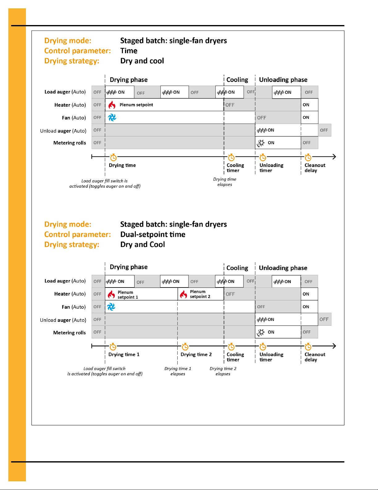
Appendix B: Grain Drying Graphs
NOTE: To apply the dry and cool strategy with a single-fan dryer: a) select either the Time or Dual-Set-
point Time control scheme; b) set the Cooling Timer to an appropriate value (a value other
than 0 seconds); c) place the Heater and Fan switches in the Auto position on the control
panel. See Drying Grain in Staged Batch, page 63 for the complete drying procedure.
96 PNEG-1851 Vision N2
Page 97

C Messages
Topics Covered in this Appendix
▪ The Status Messages
The Status Messages
Displayed in the status bar, status messages are either general or specific to the chosen drying mode and
constantly notify you of the dryer’s current state.
Table C-1 Status messages for both the continuous flow and staged batch modes
Message Drying modes Occurrence Description
Dryer Started Continuous flow,
staged batch
Dryer Stopped Continuous flow,
staged batch
Loading
Drying
Hi-Heat Drying
(time)
Hi-Heat Drying
(temp)
Continuous flow,
staged batch
Continuous flow,
staged batch
Staged batch Displayed during the drying
Staged batch
Displayed once Start is pressed
on the control panel
Displayed once Stop is pressed
on the control panel, or Stop
Dryer is clicked on your dryer’s
remote web application
Displayed when the load auger
is turning
In staged batch, displayed
during the drying phase in either
the time or time and temperature
control scheme, once the drying
time starts
phase in the dual-setpoint time
control scheme, once drying
time 1 starts
Displayed during the drying
phase in the dual-setpoint temperature control scheme, before
the grain setpoint 1 is reached
The dryer is in operation
The dryer is not in operation
Indicates the time remaining on
the out of grain timer
In staged batch, indicates the
time remaining on the drying timer
of the selected control scheme
(time or time and temperature)
Indicates the time remaining on
the drying 1 timer
Indicates the difference (in
degrees) between grain setpoint 1
and the grain’s actual
temperature
Low-Heat Drying
(time)
Low-Heat Drying
(temp)
Cooling Staged batch
PNEG-1851 Vision N2 97
Staged batch
Staged batch
Displayed during the drying
phase in the dual-setpoint time
control scheme, once drying
time 2 starts
Displayed during the drying
phase in the dual-setpoint temperature control scheme, before
the grain setpoint 2 is reached
Displayed during the cooling
phase
Indicates the time remaining on
the drying 2 timer
Indicates the difference (in
degrees) between grain setpoint 2
and the grain’s actual
temperature
Indicates the time remaining on
the cooling timer
Page 98

Appendix C: Messages
Table C-1 Status messages for both the continuous flow and staged batch modes (cont'd.)
Message Drying modes
Unloading
Unloading
Cleanout
Dryer Cooling
Down
Emergency
Cooling
Temperature
Hold
Staged batch
Continuous flow,
staged batch
Continuous flow,
staged batch
Continuous flow,
staged batch
Staged batch
Occurrence
Displayed during the unloading
phase
Displayed when the cleanout
delay is active
Displayed when the cool-down
timer is active
Displayed once an emergency
cooling has been initiated, in
response to a grain overheat
shutdown
Displayed during the drying
phase in either the time or time
and temperature control
scheme, once the drying timer
elapses and the grain temperature has yet to reach its setpoint
Description
Indicates the time remaining on
the unloading timer
Indicates the time remaining on
the cleanout delay
The dryer is not running, but the
fans are in operation throughout
the duration of the cool-down time
Indicates the time remaining on
the cool-down timer
Indicates the difference (in
degrees) between the grain temperature setpoint and the grain’s
actual temperature
98 PNEG-1851 Vision N2
Page 99

D List of Parameters
Topics Covered in this Appendix
▪ Vision N2 Parameters for Portable Dryers
Vision N2 Parameters for Portable Dryers
The menus in your dryer’s graphical interface contain parameters that are used to control a wide range of
operating features. This section lists all of these parameters and provides a brief description of each one.
Wet Sensor Calibration (Loading Menu)
Incoming Grain Moisture — The wet grain’s actual moisture level (%).
Incoming Grain Temperature — The wet grain’s actual temperature (°F; °C)
Out of Grain Timer (Loading Menu)
Out of Grain Timer — The timer that starts once the load auger begins to turn and stops when the dryer
wet bin is full. If it elapses, a shutdown message alerts you that the wet grain storage bin supplying the
dryer is empty. The Load Auger switch must be in the Auto position for the out of grain timer to work.
Plenum Setpoints (Drying Menu)
Plenum Setpoints — The desired temperature inside the plenum. In a multi fan and heater configuration,
plenum 1 always refers to the one that is closest to ground level.
Plenum Setpoints for Stages 1 and 2 (Drying Menu)
Plenum Setpoints for Stage 1 — In the dual-setpoint temperature control scheme in staged batch, the
first of two temperature setpoints within the same plenum. The grain temperature must reach this setpoint
before switching to the plenum setpoint for stage 2.
Plenum Setpoints for Stage 2 — In the dual-setpoint temperature control scheme in staged batch, the
last of two temperature setpoints within the same plenum. The plenum temperature switches to this setpoint only after the grain temperature reaches the plenum setpoint for stage 1.
Cooling Timer (Cooling Menu)
Cooling Timer — The length of time that the fans run to cool the grain. This timer is only available in
staged batch mode.
Cool-Down Time (Cooling Menu)
Cool-Down Time — The length of time that the fans run following a shutdown error, except when shut-
downs related to the plenums, high grain temperatures, and fan motor overloads occur; in these instances,
the cool-down time is not in effect. This timer is only available in staged batch mode.
PNEG-1851 Vision N2 99
Page 100

Appendix D: List of Parameters
Dry Sensor Calibration (Unloading Menu)
Outgoing Grain Moisture — The dry grain’s actual moisture level (%).
Outgoing Grain Temperature — The dry grain’s actual temperature (°F; °C)
Unload Timer (Unloading Menu)
Unload Timer — The length of time that the unload auger runs to unload the grain. This timer is only avail-
able in staged batch mode.
Unload Speed in Manual Mode (Unloading Menu)
Unload Speeds Entered in — The units of measure (bushels or metric tons per hour, or metering roll
speed %) that the unload speed value is entered in.
Adjusted Speed — The speed that the metering rolls turn at when the Unload Auger switch is in the On
position. Enter the speed value that corresponds to your dryer’s configuration and your chosen drying
operation (full-heat or dry and cool).
Incremental Adjustment — The incremental adjustment of the metering roll speed in manual mode.
Unload Speeds (Unloading Menu)
Unload Speeds Entered in — The units of measure (bushels or metric tons per hour, or metering roll
speed %) that the unload speed value is entered in.
Adjusted Speed — In either the 1-speed temperature control scheme in continuous flow or any of the control schemes in staged batch, the adjusted speed that the metering rolls turn at when the Unload Auger
switch is in the Auto position.
Incremental Adjustment — The incremental adjustment of the metering rolls’ actual speed in auto mode.
High Speed — In the 2-speed temperature control scheme in continuous flow, a read-only value of the
high-limit metering roll speed. If the grain temperature rises 1°F (0.56°C) above its setpoint, the metering
rolls turn at this speed setting. Adjusting this value incrementally does not alter the value that is set in the
2-Speed Temperature (Continuous Flow) window.
Low Speed — In the 2-speed temperature control scheme in continuous flow, a read-only value of the
low-limit metering roll speed. If the grain temperature drops 1°F (0.56°C) below the setpoint, the metering
rolls turn at this speed setting. Adjusting this value incrementally does not alter the value that is set in the
2-Speed Temperature (Continuous Flow) window.
Speed 5 — In the 5-speed temperature control scheme in continuous flow, a read-only value that is equal
to the reference speed plus the outer speed offset. Adjusting this value incrementally does not alter the
value of the offset that is set in the 5-Speed Temperature (Continuous Flow) window.
Speed 4 — In the 5-speed temperature control scheme in continuous flow, a read-only value that is equal
to the reference speed plus the inner speed offset. Adjusting this value incrementally does not alter the
value of the offset that is set in the 5-Speed Temperature (Continuous Flow) window.
Reference Speed — A read-only value of the metering roll’s setpoint (or reference) speed. Adjusting this
value incrementally does not alter the value of the reference speed that is set in the 5-Speed Temperature
(Continuous Flow) window.
Speed 2 — In the 5-speed temperature control scheme in continuous flow, a read-only value that is equal
to the reference speed minus the inner speed offset. Adjusting this value incrementally does not alter the
value of the offset that is set in the 5-Speed Temperature (Continuous Flow) window.
100 PNEG-1851 Vision N2
 Loading...