

Page 1
PNEG-1842
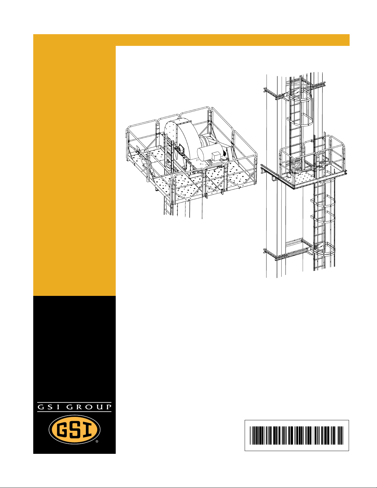
42"-48" Bucket Elevator Platform
and Ladder “X” Series
Installation Manual
PNEG-1842
Date: 03-13-12
Page 2

Use of the equipment information page will help you identify the equipment in the case that you need to
call your dealer or installer. This information should be filled out and kept on record.
Equipment Information
Model #:___________________________________________
Serial #:____________________________________
Date Purchased:____________________________________
Dealer/Distributor Name and Phone #:___________________________________________
Material Handling
1004 E. Illinois St.
Assumption, IL. 62510
Phone: 1-217-226-4421
2 PNEG-1842 42"-48" Bucket Elevator Platform and Ladder “X” Series
Page 3

Table of Contents
Contents
Chapter 1 Introduction .......................................................................................................................................... 5
Chapter 2 Safety ..................................................................................................................................................... 6
Safety Guidelines .................................................................................................................................. 6
Safety Instructions ..................... ... .... .......................................... ... ... ..................................................... 7
Chapter 3 Decal Location ...................................................................................................................................... 9
Chapter 4 Overview ............................................................................................................................................. 10
Chapter 5 Ladder Assembly ............................................................................................................................... 11
Typical Ladder/Cage Setup ................................................................................................................. 20
Chapter 6 Tie Angles, Ladders and Safety Cages ............................................................................................ 21
Attach Tie Angle to Boot Trunking ................................................ ... ... ... .... ... ... ... .... ... ... ... ... .... ...... ... ... 21
Attach Boot Ladder Support Brackets to Boot Tie Angle .... ... .... ... ... ... ... .... ... ... ... .... ... ... ... ... .... ... ... ... ... 22
Install Boot Ladder Section ................................................................................................................. 24
Attach Tie Angles to Trunking ............................................................................................................. 27
Attach Ladder Support Brackets to Tie Angles for 42" ........ .................................... ............................ 30
Attach Ladders to Ladder Support Brackets for 42" ............................................................................ 32
Attach Ladder Support Brackets to Tie Angles for 48" ........ .................................... ............................ 33
Attach Ladders to Ladder Support Brackets for 48" ............................................................................ 35
Safety Cage Installation ......... ... ... .... ... .......................................... ... ... ... .... ... ... ... .... ... ... ... .......... ... ... ... 36
Install Safety Cage .............................................................................................................................. 37
Chapter 7 Rest Platform ...................................................................................................................................... 40
Install Rest Platform Tie Angles to Trunking ....................................................................................... 40
Install Rest Platform Mounting Channels ............................................................................................ 42
Install Rest Platform Cross Channels ................................................................................................. 43
Install Rest Platform Deck Plate .......................................................................................................... 44
Install Handrail Posts .......................................................................................................................... 46
Assemble Intermediate Handrails .... ... ... ... ... .... ................................................................................... 47
Install Handrails to Posts ..................................................................................................................... 48
Install Ladder Support Brackets .......................................................................................................... 49
Chapter 8 42" Head Platform Left Hand Drive ................................................................................................... 51
Attach Cross Deck Support Channels to Lower Head ........................................................................ 51
Attach Toe Board Channels to Cross Support Channels .................................... .... ... ... ...................... 54
Deck Channel Support Angle to Cross Channel .................... .... ... ... ....................................... ... ... ... ... 56
Decking Installation ....................................................................................................................... ...... 58
Install Toe Boards ............................................................................................................................... 61
Splice Toe Boards Together ............................................................................................................... 62
Down-Leg Hatch Side Decking Section .............................................................................................. 63
Install Handrail Supports ............................................................................................................... ... ... 64
Install Platform Post ......................................................................................................................... ... 65
Install Handrails ................................................................................................................................... 66
Attach Intermediate Handrails to Posts ............................................................................................... 67
Install the Hatch ............................................................................................................................ ... ... 68
PNEG-1842 42"-48" Bucket Elevator Platform and Ladder “X” Series 3
Page 4

Table of Contents
Chapter 9 48" Head Platform Right Hand Drive ................................................................................................ 71
Attach Cross Support Channels to Lower Head ................................................................................. 71
Attach Toe Board Channels to Cross Support Channels .................. .................................................. 76
Deck Channel Support Angle to Channel Supports ............................................................................ 77
Decking Installation ............................................................................................................................. 78
Install Toe Boards ............................................................................................................................... 83
Splice Toe Boards Together ............................................................................................................... 84
Install Handrail Supports ..................................................................................................................... 85
Install Platform Post ............................................................................................................................ 86
Install Handrails ................................................................................................................................... 87
Attach Intermediate Handrails to Posts ............................................................................................... 88
Install the Hatch .................................................................................................................................. 89
Attach Knee Braces to Platform and Trunking (48" Only) ................................................................... 92
Chapter 10 6 x 6 Distributor Platforms ............................................................................................................... 94
42" Platform Clamps .......................................................................................................................... 94
48" Platform Clamps .......................................................................................................................... 95
Support Channels and Knee Braces ................................................................................................. 96
Cross Braces for Knee Braces .......................................................................................................... 97
Toe Boards ............................ ... .......................................... .......................................... ..................... 99
Platform Decking ................................................................... .... ... ... ... ... .... ... ... ... .... ......................... 101
Platform Post ......................... ... ... .... ... ... ... .......................................... ... .... ...................................... 103
Tie Braces ....................................................................................................................................... 104
Intermediate Handrail ...................................................................................................................... 105
Upper Handrails ............................................................................................................................... 106
Safety Gate Package (If Ordered as Optional) (DSP-1648GATE) .................................................. 109
Distributor Platform Support (48" Only) . ... .......................................... ... .... ... ... ... .... ......................... 111
Chapter 11 Warranty .......................................................................................................................................... 113
4 PNEG-1842 42"-48" Bucket Elevator Platform and Ladder “X” Series
Page 5

1. Introduction
Chapter 1: Introduction
READ THIS MANUAL carefully to learn how to properly use and install equipment. Failure to do so could
result in personal injury or equipment damage.
INSPECT the shipment immediately upon arrival. The customer is responsible for ensuring that all
quantities are correct. The customer should report and note any damage or shortage on the bill of
lading to justify their claim to the transport company.
THIS MANUAL SHOULD BE CONSIDERED a permanent part of your equipment and should be easily
accessible when needed.
This warranty provides you the assurance that the company will back its products when defects appear
within the warranty period. In some circumstances, the company also provides field improvements, often
without charge to the customer, even if the product is out of warranty. Should the equipment be abused,
or modified to change its performance beyond the factory specifications, the warranty will become void
and field improvements may be denied.
PNEG-1842 42"-48" Bucket Elevator Platform and Ladder “X” Series 5
Page 6
2. Safety
This is the safety alert symbol. It is used to alert you
to potential personal injury hazards. Obey all safety
messages that follow this symbol to avoid possible
injury or death.
WARNING indicates a hazardous situation which, if not
avoided, could result in death or serious injury.
CAUTION, used with the safety alert symbol, indicates a
hazardous situation which, if not avoided, could result in
minor or moderate injury.
NOTICE is used to address practices not related to
personal injury.
DANGER indicates a hazardous situation which, if not
avoided, will result in death or serious injury.
Chapter 2: Safety
Safety Guidelines
This manual contains information that is important for you, the owner/operator, to know and understand.
This information relates to protecting personal safety and preventing equipment problems. It is the
responsibility of the owner/operator to inform anyone operating or working in the area of this equipment
of these safety guidelines. To help you recognize this information, we use the symbols that are defined
below. Please read the manual and pay attention to these sections. Failure to read this manual and its
safety instructions is a misuse of the equipment and may lead to serious injury or death.
DANGER
WARNING
CAUTION
NOTICE
6 PNEG-1842 42"-48" Bucket Elevator Platform and Ladder “X” Series
Page 7
2. Safety
Follow Safety Instructions
Carefully read all safety messages in this manual and
safety signs on your machine. Keep signs in good
condition. Replace missing or damaged safety signs. Be
sure new equipment components and repair parts include
the current safety signs. Replacement safety signs are
available from the manufacturer.
Learn how to operate the machine and how to use controls
properly. Do not let anyone operate without instruction.
Keep your machinery in proper working condition.
Unauthorized modifications to the machine may impair
the function and/or safety and affect machine life.
If you do not understand any part of this manual or need
assistance, contact your dealer.
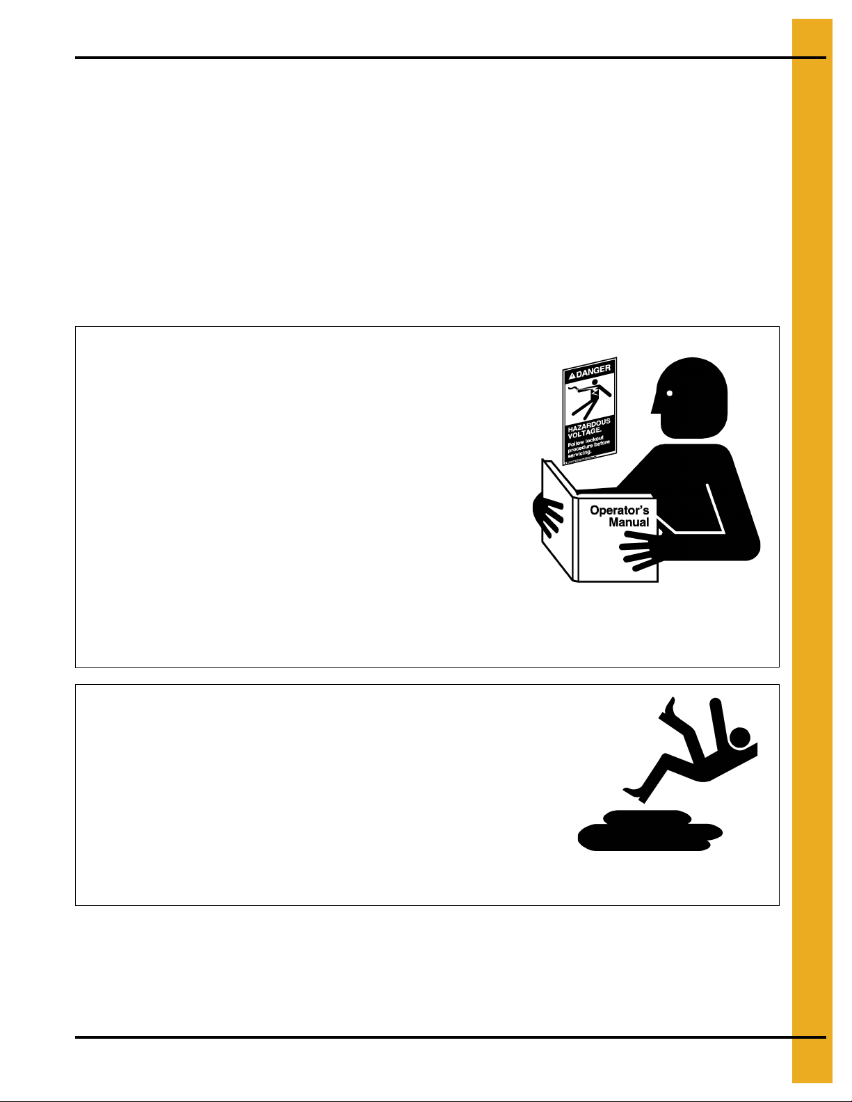
Read and Understand Manual
Practice Safe Maintenance
Understand service procedures before doing work. Keep area
clean and dry.
Never lubricate, service, or adjust machine while it is in operation.
Keep hands, feet, and clothing away from rotating parts.
Keep all parts in good condition and properly installed. Fix
damage immediately . Replace worn or broken p arts. Remove any
built-up grease, oil, and debris.
Maintain Equipment
and Work Area
Safety Instructions
Our foremost concern is your safety and the safety of others associated with this equipment. We want to
keep you as a customer. This manual is to help you understand safe operating procedures and some
problems that may be encountered by the operator and other personnel.
As owner and/or operator, it is your responsibility to know what requirements, hazards, and precautions
exist, and to inform all personnel associated with the equipment or in the area. Safety precautions may be
required from the personnel. Avoid any alterations to the equipment. Such alterations may produce a very
dangerous situation where SERIOUS INJURY or DEATH may occur.
This equipment shall be installed in accordance with the current installation codes and applicable
regulations, which should be carefully followed in all cases. Authorities having jurisdiction should be
consulted before installations are made.
PNEG-1842 42"-48" Bucket Elevator Platform and Ladder “X” Series 7
Page 8
2. Safety
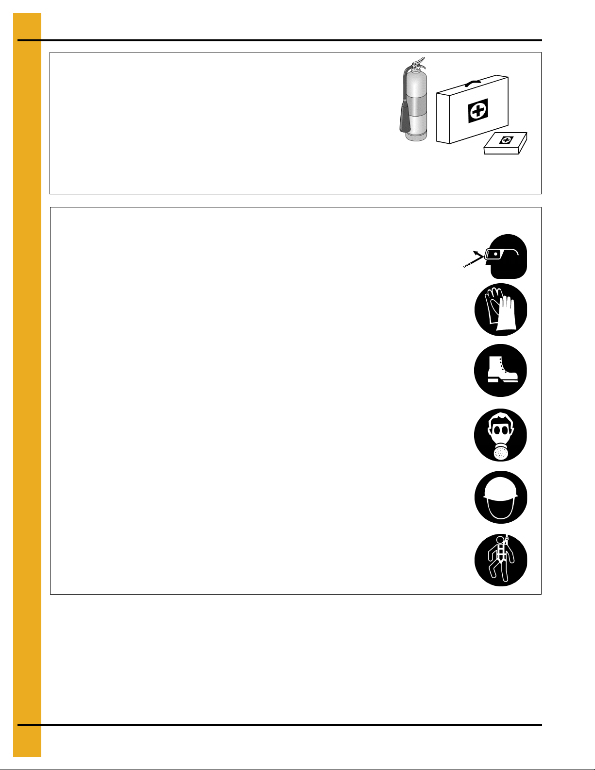
Prepare for Emergencies
Be prepared if fire starts.
Keep a first aid kit and fire extinguisher handy.
Keep emergency numbers for doctors, ambulance service,
hospital, and fire department near your telephone.
Keep Emergency Equipment
Quickly Accessible
Wear Protective Clothing
Wear close-fitting clothing and safety equipment appropriate
to the job.
Remove all jewelry.
Tie long hair up and back.
Wear safety glasses at all times to protect eyes from debris.
Wear gloves to protect your hands from sharp edges on
plastic or steel parts.
Wear steel-toed boots to help protect your feet from falling
debris. Tuck in any loose or dangling shoestrings.
A respirator may be needed to prevent breathing potentially
toxic fumes and dust.
Wear a hard hat to help protect your head.
Wear appropriate fall protection equipment when working at
elevations greater than six feet (6').
Eye Protection
Gloves
Steel-Toed Boots
Respirator
Hard Hat
Fall Protection
8 PNEG-1842 42"-48" Bucket Elevator Platform and Ladder “X” Series
Page 9
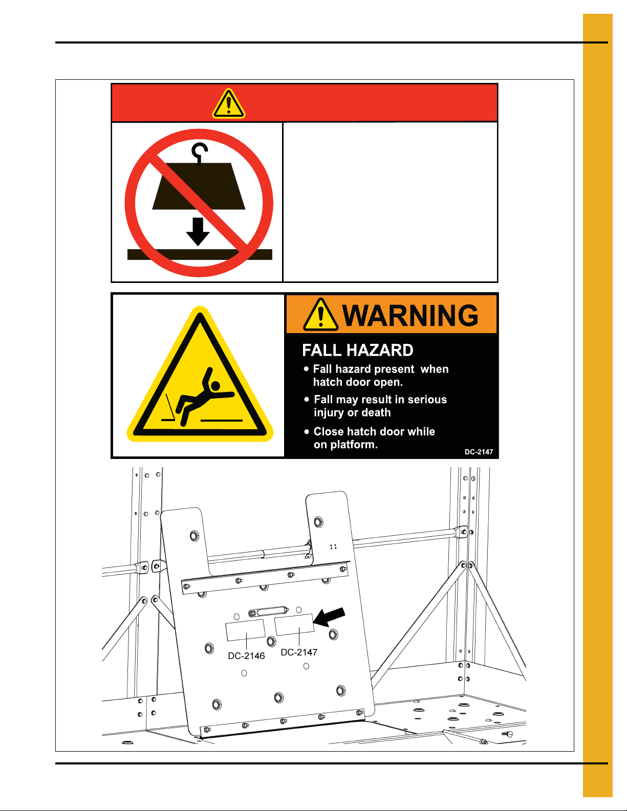
Chapter 3: Decal Location
DO NOT EXCEED
PLATFORM LOAD LIMIT
DC-2146
Excessive load will damage
platform and cause
platform to fall.
Load limit = 500 LBS. (2.25 kN)
DANGER
> 500 lbs
(2.25 kN)
Injury or death will result.
3. Decal Location
PNEG-1842 42"-48" Bucket Elevator Platform and Ladder “X” Series 9
Page 10

4. Overview
Chapter 4: Overview
This section is intended to provide a general, high-level overview of platform assembly for the GSI bucket
elevator. Detailed instructions are given in the pages to come.
This section should be used for reference only and is intended to provide general guidance about the
overall process only.
1. Support Channels:
Proper orientation of channels is based upon the size of the bucket elevator (42" or 4") and the
right/left hand position of the drive. This must be installed correctly at the start or nothing else will
install correctly.
2. Ladders and Safety Cages:
Ladder sections mount directly to the trunking sections of the bucket elevator. Typical ladder layouts
and charts identifying the support height for ladder packages can be found o n Pages 11 through 20.
3. Tie Angles to Trunking:
• Proper orientation of the tie angles is critical for correct installation.
• Note differences from up-leg and down-leg installations.
Be sure to follow the instructions for the size and drive position.
Throughout this manual, particular attention is given to the initial orientation of channels and aligning
bolt holes. Failure to complete these initial steps correctly will significantly impede the assembly and
installation of the bucket elevator platforms.
4. Decking and Toe Boards:
Decking is etched with alpha characters to assist with orienting decks and aligning holes for
connections. Decking connections should be finger-tight only initially so that adjustments can be
made once all decks and toe boards are in place. Only then should all hardware be fully torqued.
5. Handrail Platform Posts:
The number and location of platform posts varies based upon platform and bucket elevator size.
6. Handrails:
Intermediate handrails (those at near knee level) may need to be field cut to fit. The amount to trim
varies based upon the size of the platform being insta lled. The smaller rail then fits inside of the larger
rail so that it “telescopes” between the posts. Always follow best practices of “measure twice, cut
once” and verify the measurement is for the bucket elevator size. Upper handrails do not require any
alterations in the field prior to assembly.
7. Platform Braces:
Throughout this manual, safety cage bars (LDR-517BE) are used as platform braces. These are
required for support and stability. Please attach as described through the manual.
10 PNEG-1842 42"-48" Bucket Elevator Platform and Ladder “X” Series
Page 11
5. Ladder Assembly
Chapter 5: Ladder Assembly
The ladder sections are to be mounted directly to the trunking sections. Quantities and section lengths may
vary depending on overall height of system. If you have a non-standard height system, refer to supported
bucket height reference chart
Part # Supported Bucket Height (Ft.) Part # Supported Bucket Height (Ft.)
42XRLAD50 50-59 42XWLAD50 50-59
below
and
on Page 12
for the correct ladder package for the system.
Supported Bucket Height Reference Chart for 42"
42XRLAD60 60-69
42XRLAD70 70-79 42XWLAD70 70-79
42XRLAD80 80-89
42XRLAD90 90-99 42XWLAD90 90-99
42XRLAD100 100-109
42XRLAD110 110-119 42XWLAD110 110-119
42XRLAD120 120-129
42XRLAD130 130-139 42XWLAD130 130-139
42XRLAD140 140-149
42XRLAD150 150-159 42XWLAD150 150-159
42XRLAD160 160-169
42XRLAD170 170-179 42XWLAD170 170-179
42XRLAD180 180-189
42XRLAD190 190-199 42XWLAD190 190-199
42XRLAD200 200-209
42XRLAD210 210-219 42XWLAD210 210-219
42XWLAD60 60-69
42XWLAD80 80-89
42XWLAD100 100-109
424WLAD120 120-129
42XWLAD140 140-149
42XWLAD160 160-169
42XWLAD180 180-189
42XWLAD200 200-209
42XRLAD220 220-229
42XRLAD230 230-239 42XWLAD230 230-239
42XWLAD220 220-229
PNEG-1842 42"-48" Bucket Elevator Platform and Ladder “X” Series 11
Page 12
5. Ladder Assembly
Due to O.H.S.A. standards, it is required that a rest platform be installed every 30'.
Part # Supported Bucket Height (Ft.) Part # Supported Bucket Height (Ft.)
48XRLAD50 50-59 48XWLAD50 50-59
Supported Bucket Height Reference Chart for 48"
48XRLAD60 60-69
48XRLAD70 70-79 48XWLAD70 70-79
48XRLAD80 80-89
48XRLAD90 90-99 48XWLAD90 90-99
48XRLAD100 100-109
48XRLAD110 110-119 48XWLAD110 110-119
48XRLAD120 120-129
48XRLAD130 130-139 48XWLAD130 130-139
48XRLAD140 140-149
48XRLAD150 150-159 48XWLAD150 150-159
48XRLAD160 160-169
48XRLAD170 170-179 48XWLAD170 170-179
48XRLAD180 180-189
48XRLAD190 190-199 48XWLAD190 190-199
48XRLAD200 200-209
48XRLAD210 210-219 48XWLAD210 210-219
48XWLAD60 60-69
48XWLAD80 80-89
48XWLAD100 100-109
48XWLAD120 120-129
48XWLAD140 140-149
48XWLAD160 160-169
48XWLAD180 180-189
48XWLAD200 200-209
48XRLAD220 220-229
48XRLAD230 230-239 48XWLAD230 230-239
48XWLAD220 220-229
NOTE: Ladders are of a modular design for ease of modification in the field. These illustrations are only
to be used as a “general” guide to installation layout. The exact assembly may vary due to the unique
nature of each bucket elevator.
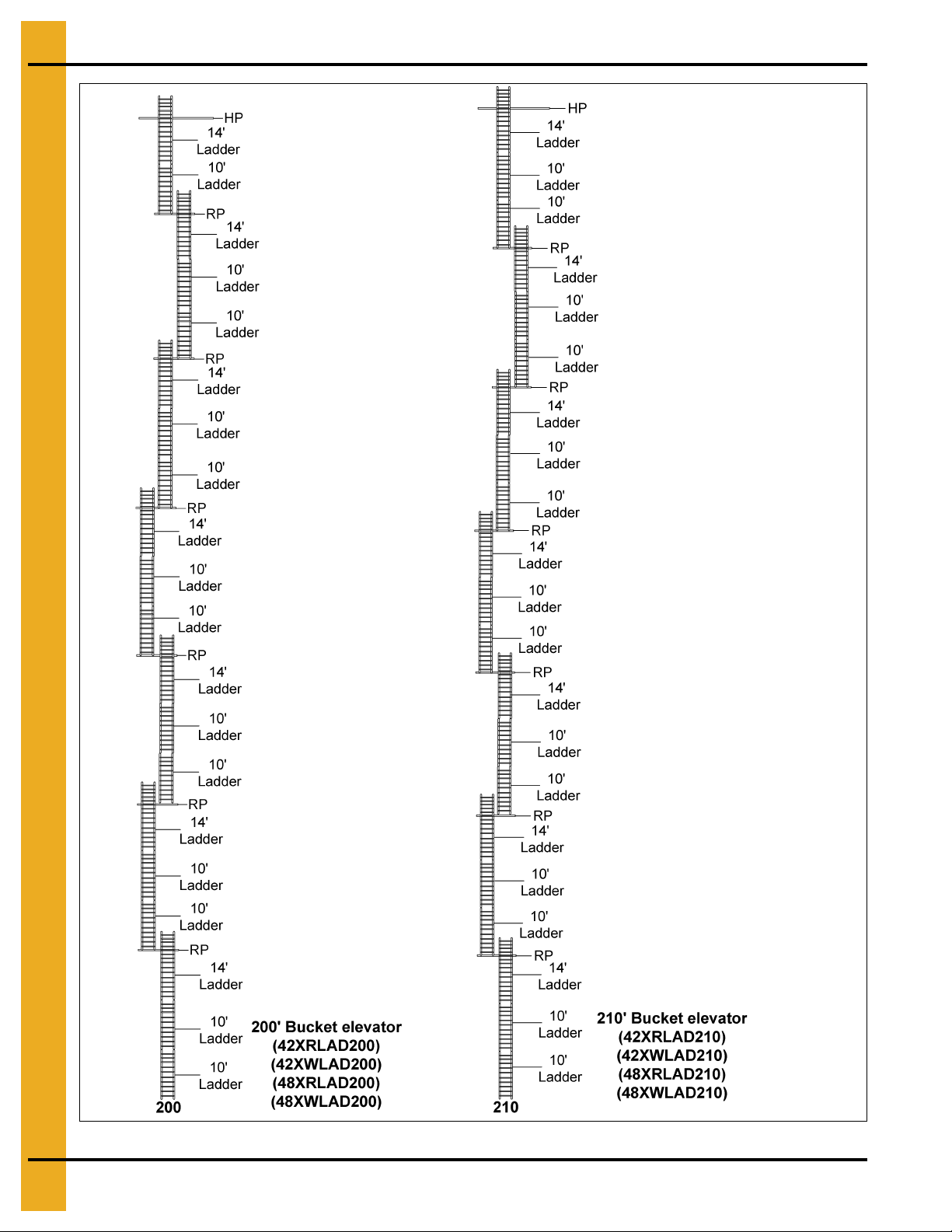
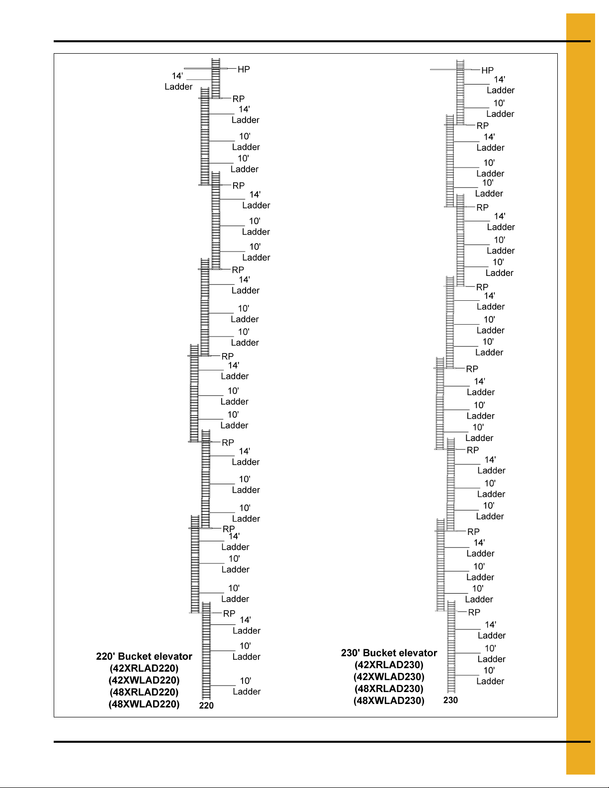
See Figures 5A-5G on Pages 13-19 to help determine if the ladders should be started on the up-leg or
down-leg of the elevator and also aid in the ladder order and rest platform locations for bucket elevators
with heights from 50' through 230'.
CAUTION
12 PNEG-1842 42"-48" Bucket Elevator Platform and Ladder “X” Series
Page 13
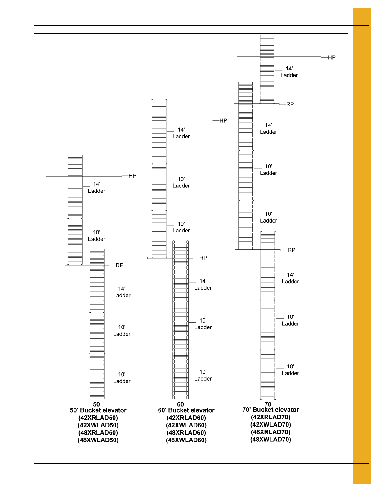
5. Ladder Assembly
Key: HP = Head Platform
RP = Rest Platform
PNEG-1842 42"-48" Bucket Elevator Platform and Ladder “X” Series 13
Figure 5A
Page 14
5. Ladder Assembly
Key: HP = Head platform
RP = Rest platform
Figure 5B
14 PNEG-1842 42"-48" Bucket Elevator Platform and Ladder “X” Series
Page 15
5. Ladder Assembly
Key: HP = Head Platform
RP = Rest Platform
PNEG-1842 42"-48" Bucket Elevator Platform and Ladder “X” Series 15
Figure 5C
Page 16
5. Ladder Assembly
Key: HP = Head Platform
RP = Rest Platform
Figure 5D
16 PNEG-1842 42"-48" Bucket Elevator Platform and Ladder “X” Series
Page 17
5. Ladder Assembly
Key: HP = Head Platform
RP = Rest Platform
PNEG-1842 42"-48" Bucket Elevator Platform and Ladder “X” Series 17
Figure 5E
Page 18
5. Ladder Assembly
Key: HP = Head Platform
RP = Rest Platform
Figure 5F
18 PNEG-1842 42"-48" Bucket Elevator Platform and Ladder “X” Series
Page 19
5. Ladder Assembly
Key: HP = Head Platform
RP = Rest Platform
PNEG-1842 42"-48" Bucket Elevator Platform and Ladder “X” Series 19
Figure 5G
Page 20
5. Ladder Assembly
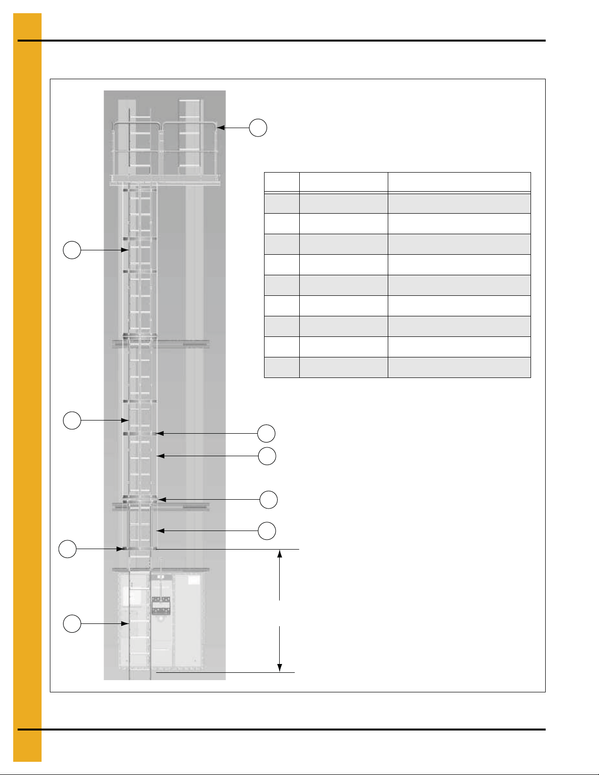
7
3
4
4
5
6
1
2
1
7'-8' to ground or
nearest platform deck
Ref # P art # Description
1 10FOOTRFWX 10' Ladder Section
1 10FOOTX 10' Ladder Section
2 LDR-BCKTBHP Safety Cage Bell Hoop - Entrance
3 LDR-3FTCAGE 3' Safety Cage Strap
4 LDR-BCKTHOOP Standard Safety Cage Hoop
5 LDR-10FTCAGE 10' Safety Cage Strap
6 14FOOTRFWX 14' Ladder Section
6 14FOOTX 14' Ladder Section
7 RP4248X Rest Platform
Typical Ladder/Cage Setup
20 PNEG-1842 42"-48" Bucket Elevator Platform and Ladder “X” Series
Figure 5H Typical Ladder/Cage Assembly Layout (30' Shown.)
Page 21
6. Tie Angles, Ladders and Safety Cages
Chapter 6: Tie Angles, Ladders and Safety Cages
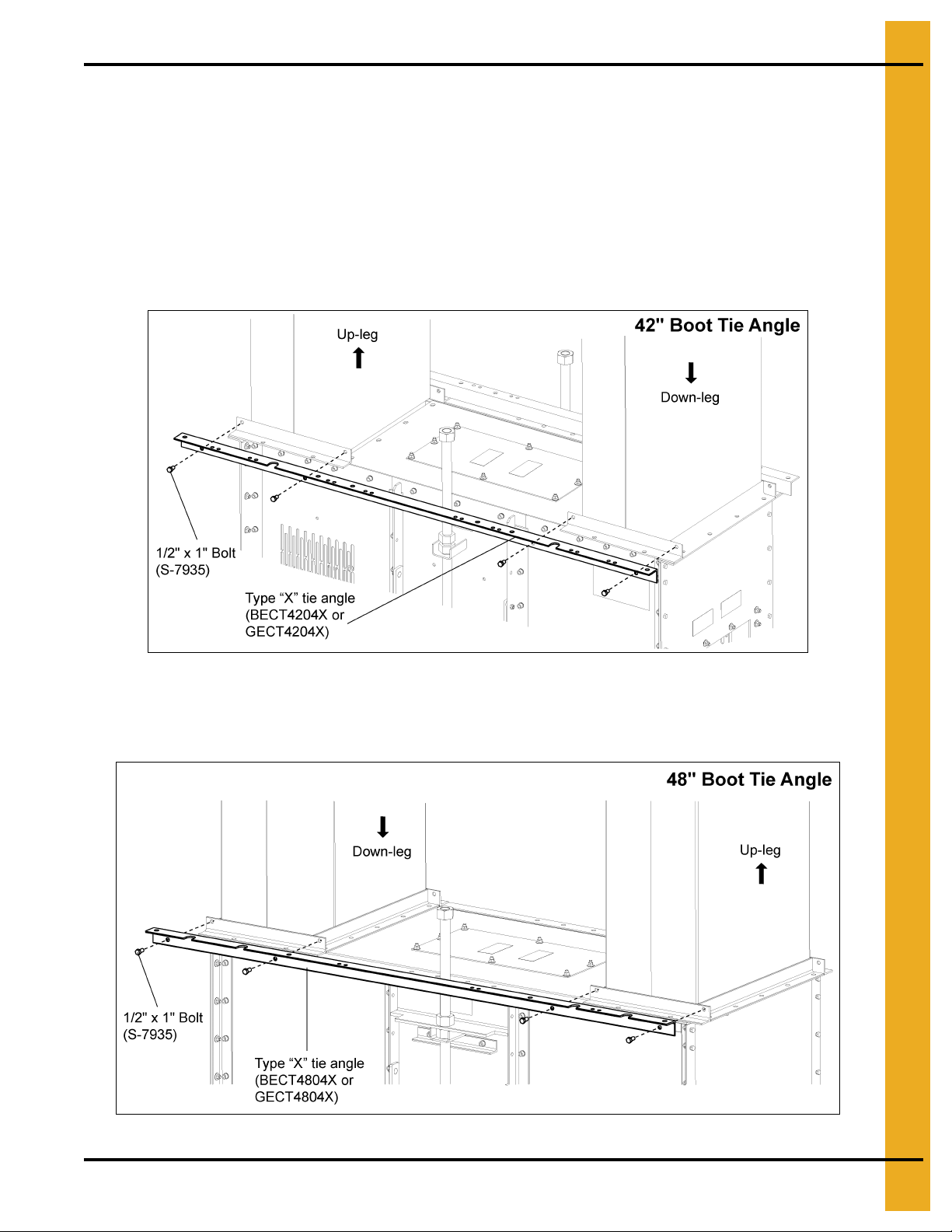
Attach Tie Angle to Boot Trunking
1. When installing the tie angles, be sure sides with the notches face out away from the trunk and the
side with the straight edge is installed against the trunking angles. Only one tie angle for the ladder
side and one tie angle for the non-ladder side is used.
a. For 42" Boot Tie Angle: Install the tie angle (GECT4204X or BECT4204X) to both sides of the
trunking attached at the boot using 1/2" x 1" HHCS bolts (S-7935) and 1/2" flange nuts (S-8506).
(See Figure 6A.)
Figure 6A 42" Boot Tie Angle
b. For 48" Boot Tie Angle: Install the tie angle (GECT4804X or BECT4804X) to both sides of the
trunking attached at the boot using 1/2" x 1" HHCS bolts (S-7935) and 1/2" flange nuts (S-8506).
(See Figure 6B.)
Figure 6B 48" Boot Tie Angle
PNEG-1842 42"-48" Bucket Elevator Platform and Ladder “X” Series 21
Page 22
6. Tie Angles, Ladders and Safety Cages
Attach Boot Ladder Support Brackets to Boot Tie Angle
NOTE: Refer to ladder layout images, Figure 5A-5G on Pages 13-19.
NOTE: Ladder can be mounted to either the up-leg or the down-leg of the elevator depending on the
height and head platform hatch location. Double check if the ladder should start on the up-leg
or down-leg.
NOTE: Both the up-leg and down-leg ladder bracket locations are shown in this manual. Actual installation
location on either the up-leg or the down-leg will be determined by owner preference.
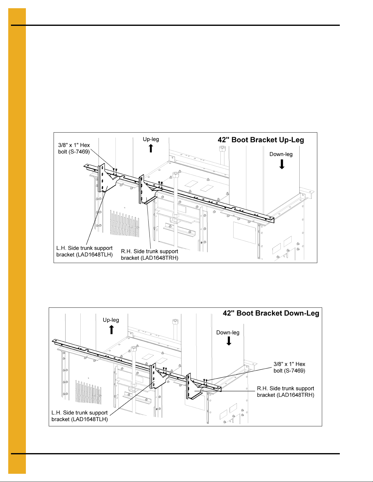
1. 42" Up-Leg Boot Brackets: Use 3/8" x 1" HHCS bolts (S-7469) and 3/8" flange nuts (S-10028) to
attach the ladder support brackets (LAD1648TRH and LAD1648TLH) to the bottom of the boot tie
angle using holes indicated. (See Figure 6C.)
Figure 6C 42" Up-Leg Boot Bracket
2. 42" Down-Leg Boot Brackets: Use 3/8" x 1" HHCS bolts (S-7469) and 3 /8" flange nuts (S-10028 )
to attach the ladder support brackets (LAD1648TRH and LAD1648TLH) to the bottom of the boot tie
angle using holes indicated. (See Figure 6D.)
Figure 6D 42" Down-Leg Boot Bracket
22 PNEG-1842 42"-48" Bucket Elevator Platform and Ladder “X” Series
Page 23
6. Tie Angles, Ladders and Safety Cages
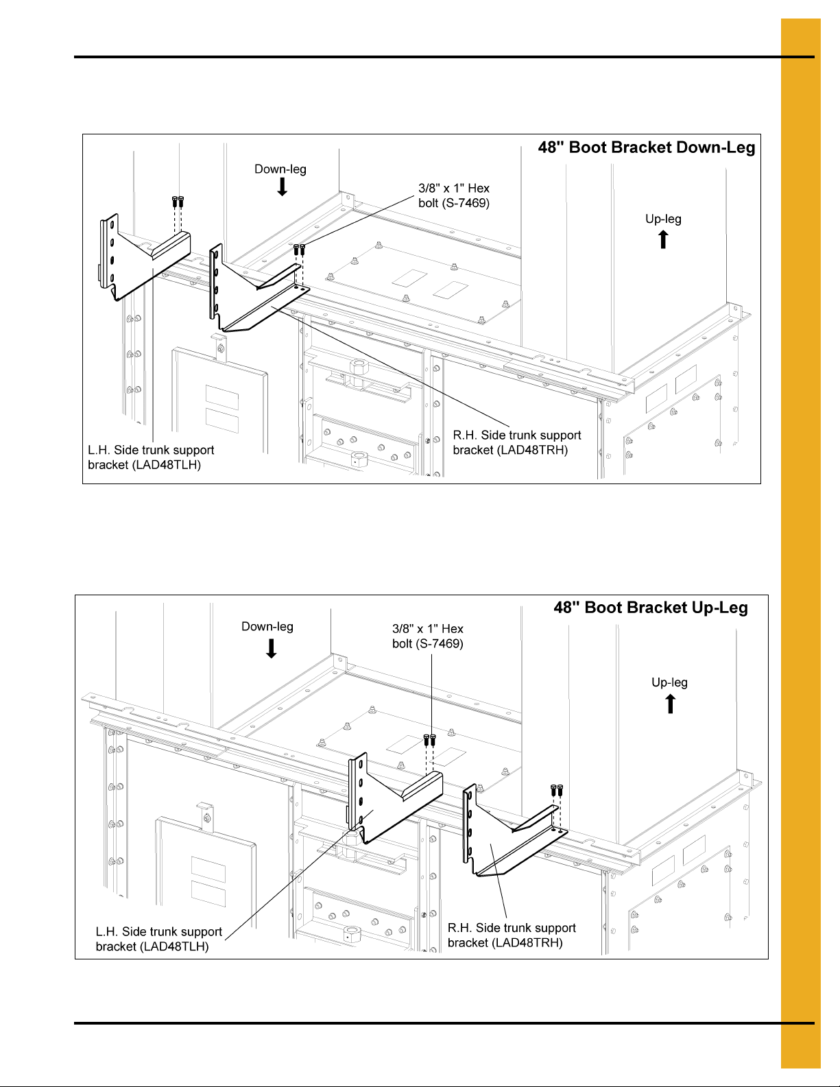
3. 48" Down-Leg Boot Brackets: Use 3/8" x 1" HHCS bolts (S-7469) and 3/8 " fla nge nu ts (S-10028)
to attach the ladder support brackets (LAD48TRH and LAD48TLH) to the top of the boot tie angle
using holes indicated. (See Figure 6E.)
Figure 6E 48" Down-Leg Boot Bracket
4. 48" Up-Leg Boot Brackets: Use 3/8" x 1" HHCS bolts (S-7469) and 3/8" flange nuts (S-10028) to
attach the ladder support brackets (LAD48TRH and LAD48TLH) to the top of the boot t ie angle using
holes indicated. (See Figure 6F.)
Figure 6F 48" Up-Leg Boot Bracket
PNEG-1842 42"-48" Bucket Elevator Platform and Ladder “X” Series 23
Page 24
6. Tie Angles, Ladders and Safety Cages
Install Boot Ladder Section
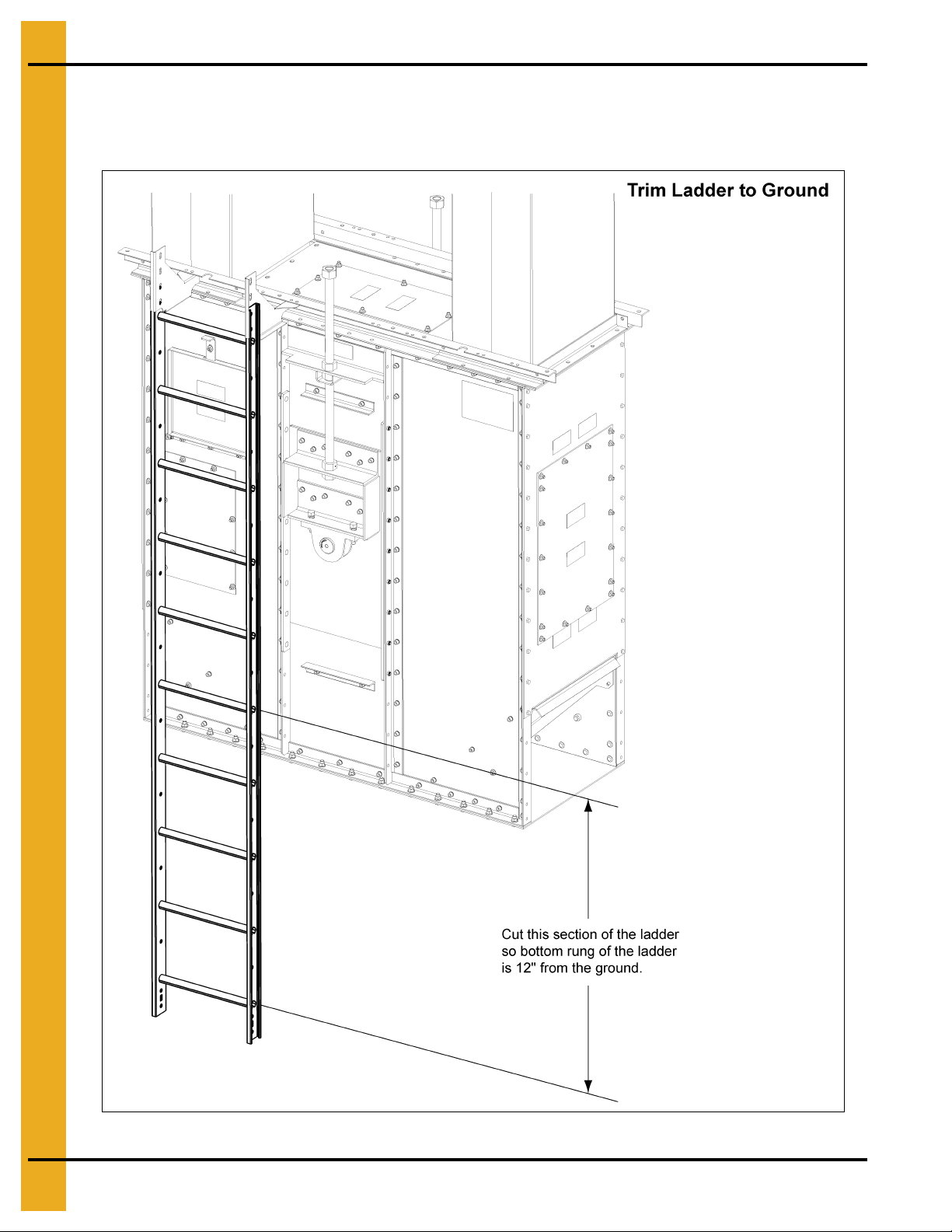
1. Trim a 10' ladder section so the first ladder rung is 12" from the ground when installed to the ladder
bracket. (See Figure 6G.)
Figure 6G Boot Ladder Section
24 PNEG-1842 42"-48" Bucket Elevator Platform and Ladder “X” Series
Page 25
6. Tie Angles, Ladders and Safety Cages
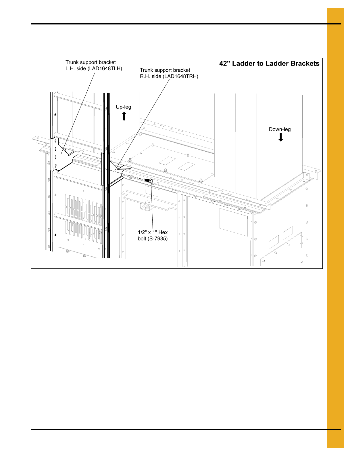
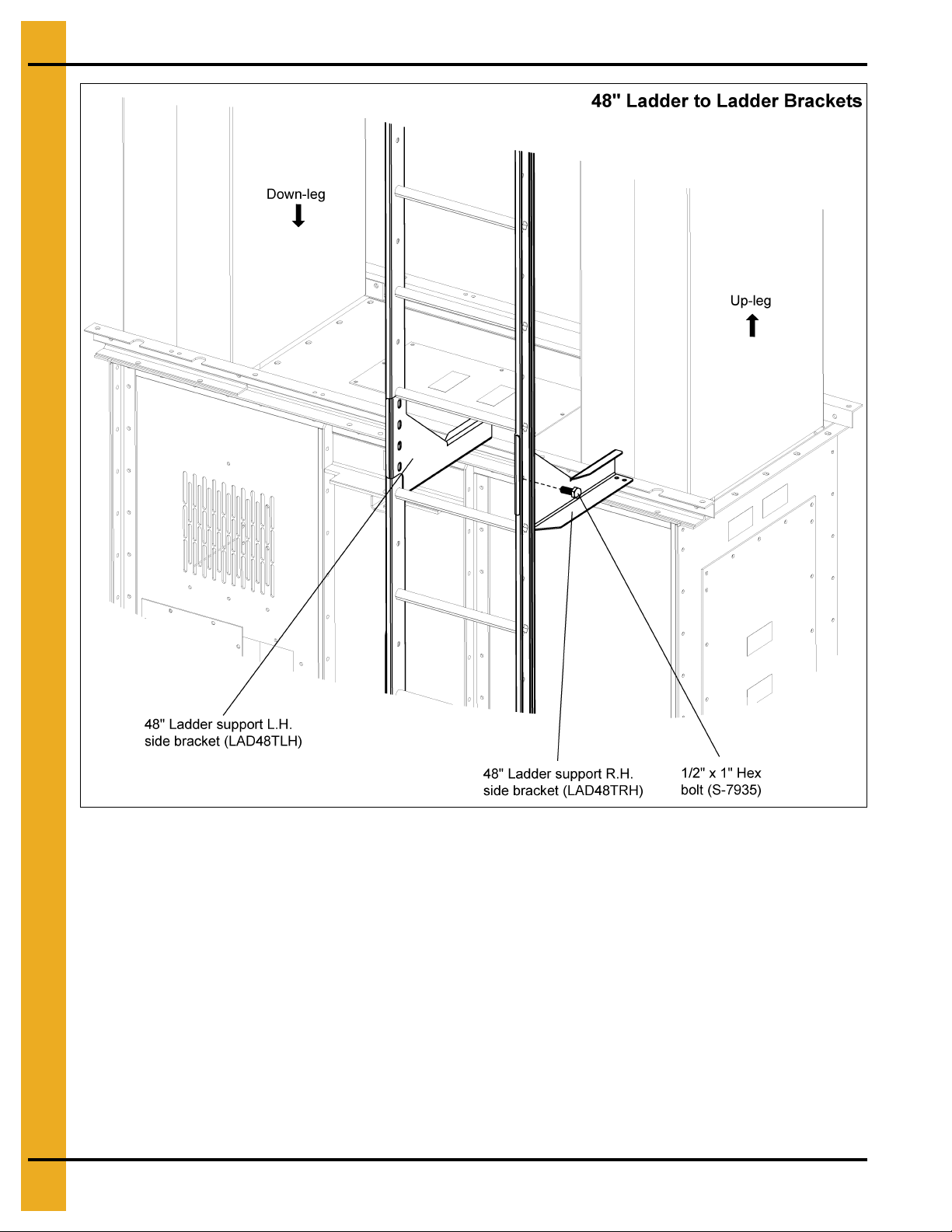
2. Attach trimmed ladder section to the left and right ladder brackets using 1/2" x 1" HHCS bolts
(S-7935) and flange nuts (S-8506) through the bottom most set of bracket holes. (See Figure 6H
below for 42" and Figure 6I on Page 26 for 48".)
Figure 6H 42" Ladder to Ladder Brackets
PNEG-1842 42"-48" Bucket Elevator Platform and Ladder “X” Series 25
Page 26
6. Tie Angles, Ladders and Safety Cages
Figure 6I 48" Ladder to Ladder Brackets
3. Attach the next ladder section to the ladder brackets using 1/2" x 1" HHCS bolts (S-7935) and flange
nuts (S-8506) through the top most set of holes.
4. Secure the bottom of the ladder to the boot or ground. NOTE: Bracket for this step is not included.
26 PNEG-1842 42"-48" Bucket Elevator Platform and Ladder “X” Series
Page 27
6. Tie Angles, Ladders and Safety Cages
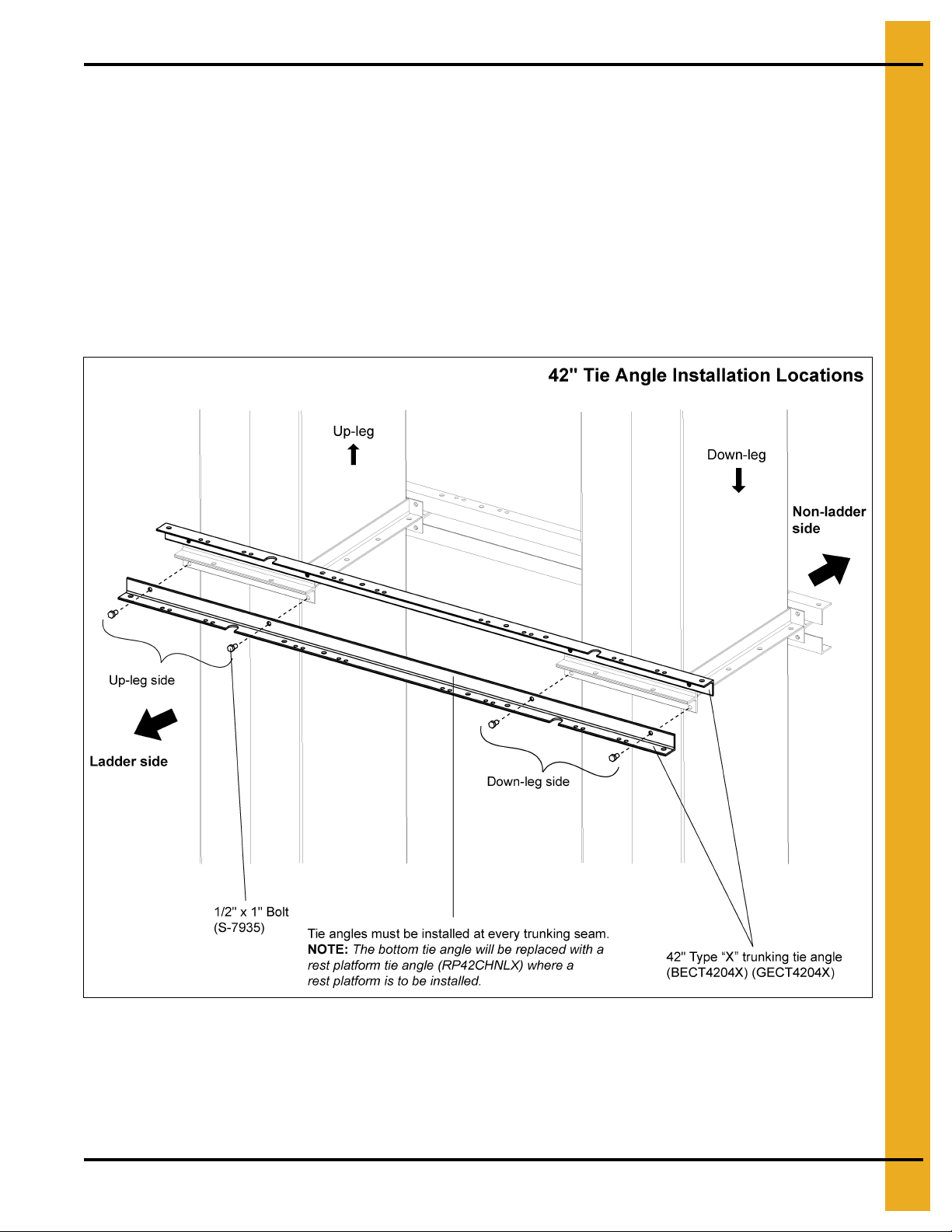
Attach Tie Angles to Trunking
NOTE: Tie angles must be installed at every trunking seam on both the ladder and non-ladder sides.
The bottom tie angle will be replaced with a rest platform tie angle (RP42CHNLX for 42" and
RPCHNLX2 for 48") where a rest platform is to be installed.
NOTE: When installing the tie angles, the notched side must face out away from the trunk and the side
with the straight edge must be installed against the trunking angles.
Two (2) tie angles are installed for both the ladder and non-ladder sides.
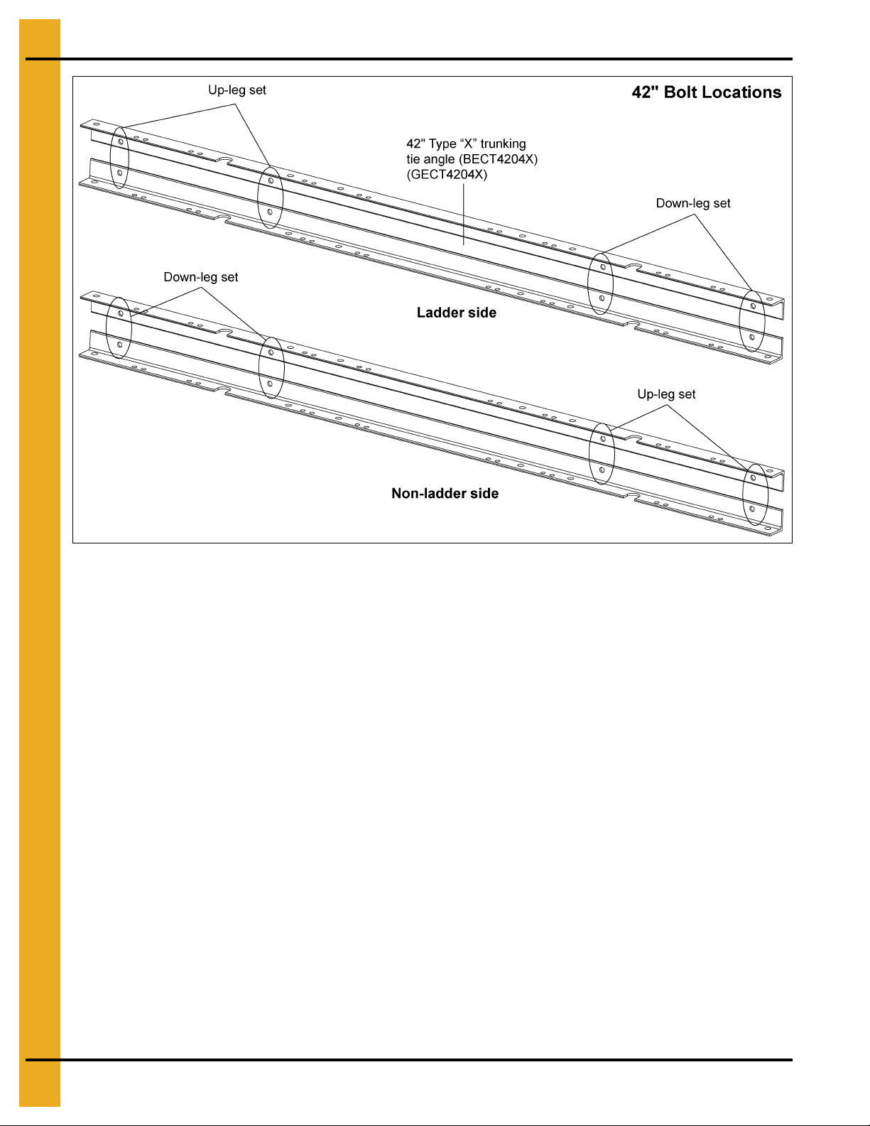
1. For 42" Tie Angles: Install two (2) tie angles (GECT4204X or BECT4204X) to both sides of the
trunking seam using 1/2" x 1" HHCS bolts (S-7935) and 1/2" flange nuts (S-8506). Installation is the
same for both the ladder and non-ladder sides. (See Figure 6J below and Figure 6K on Page 28.)
Figure 6J 42" Tie Angle Installation Locations
PNEG-1842 42"-48" Bucket Elevator Platform and Ladder “X” Series 27
Page 28
6. Tie Angles, Ladders and Safety Cages
Figure 6K 42" Bucket Elevator Tie Angles to Trunking Bolt Locations
28 PNEG-1842 42"-48" Bucket Elevator Platform and Ladder “X” Series
Page 29
6. Tie Angles, Ladders and Safety Cages
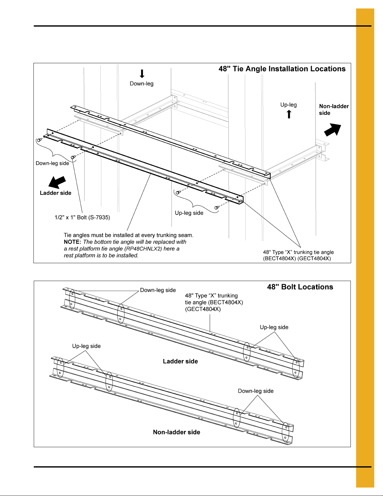
2. For 48" Tie Angles: Install two (2) tie angles (GECT4804X or BECT4804X) to both sides of the
trunking seam using 1/2" x 1" HHCS bolts (S-7935) and 1/2" flange nuts (S-8506). (See Figure 6L
and Figure 6M.)
Figure 6L 48" Tie Angle Installation Locations
Figure 6M 48" Bucket Elevator Tie Angles to Trunking Bolt Locations
PNEG-1842 42"-48" Bucket Elevator Platform and Ladder “X” Series 29
Page 30
6. Tie Angles, Ladders and Safety Cages
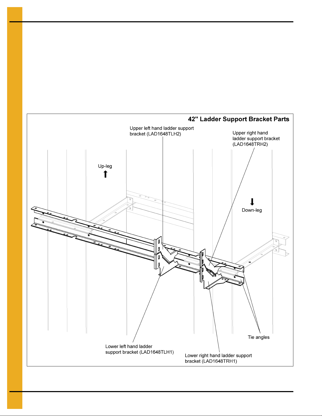
Attach Ladder Support Brackets to Tie Angles for 42"
1. For 42" Ladder Brackets: Mount the upper left and upper right hand bra ckets (LAD1 648TLH2 and
LAD1648TRH2) to the top tie angles.
2. Mount the lower left and lower right hand brackets (LAD1648TLH1 and LAD1648TRH1) to the bottom
tie angles.
3. Fasten flanges of brackets and brackets to tie angles using 3/8" x 1" HHCS bolts (S-7469) and
3/8" flange nuts (S-968). (See Figure 6N below, Figure 6O and Figure 6P on Page 31.)
NOTE: You will only use one set of brackets, either the up-leg set or the down-leg set depending on
your ladder location.
Figure 6N 42" Ladder Support Bracket Parts
30 PNEG-1842 42"-48" Bucket Elevator Platform and Ladder “X” Series
Page 31

6. Tie Angles, Ladders and Safety Cages
Figure 6O 42" Ladder Bracket Location for Down-Leg
Figure 6P 42" Ladder Bracket Location for Up-Leg
PNEG-1842 42"-48" Bucket Elevator Platform and Ladder “X” Series 31
Page 32

6. Tie Angles, Ladders and Safety Cages
Attach Ladders to Ladder Support Brackets for 42"
1. Attach the top of the ladder section to the bottom ladder support brackets.
2. Attach the bottom of the ladder section to the top ladder support brackets.
3. Fasten ladders to ladder support brackets using 1/2" x 1" HHCS bolts (S-7935) and 1/2" flange nuts
(S-8506). (See Figure 6Q for 42" connections.)
Figure 6Q
32 PNEG-1842 42"-48" Bucket Elevator Platform and Ladder “X” Series
Page 33

6. Tie Angles, Ladders and Safety Cages
Attach Ladder Support Brackets to Tie Angles for 48"
1. For 48" Ladder Brackets: Mount the upper left and upper right hand brackets (LAD48TLHTX and
LAD48TRHTX) to the top tie angles.
2. Mount the lower left and lower right hand brackets (LAD48TLHBX and LAD48TRHBX) to the bottom
tie angles.
3. Fasten flanges of brackets and brackets to tie angles using 3/8" x 1" HHCS bolts (S-7469) and
3/8" flange nuts (S-968). (See Figure 6R below, Figure 6S and Figure 6T on Page 34.)
NOTE: You will only use one set of brackets, either the up-le g set or the down-leg set depending on
your ladder location.
Figure 6R 48" Ladder Support Bracket Parts
PNEG-1842 42"-48" Bucket Elevator Platform and Ladder “X” Series 33
Page 34

6. Tie Angles, Ladders and Safety Cages
Figure 6S 48" Ladder Bracket Location for Up-Leg
Figure 6T 48" Ladder Bracket Location for Down-Leg
34 PNEG-1842 42"-48" Bucket Elevator Platform and Ladder “X” Series
Page 35

6. Tie Angles, Ladders and Safety Cages
Attach Ladders to Ladder Support Brackets for 48"
1. Attach the top of the ladder section to the bottom ladder support brackets.
2. Attach the bottom of the ladder section to the top ladder support brackets.
3. Fasten ladders to ladder support brackets using 1/2" x 1" HHCS bolts (S-7935) and 1/2" flange nuts
(S-8506). (See Figure 6U for 48" connections.)
Figure 6U
PNEG-1842 42"-48" Bucket Elevator Platform and Ladder “X” Series 35
Page 36

6. Tie Angles, Ladders and Safety Cages
Safety Cage Installation
Safety cage entrance must be installed to the ladders within 7'-8' from the ground or platform deck.
(See Figure 6V.)
Figure 6V
36 PNEG-1842 42"-48" Bucket Elevator Platform and Ladder “X” Series
Page 37

6. Tie Angles, Ladders and Safety Cages
Install Safety Cage
Safety cages are 10' sections, with the exception of the 3' entrance section.
1. Locate safety cage hoops (LDR-BCKTBHP) along the ladder rails where the safety cage hoops will
be installed. NOTE: The end hoops of a 10' section are spaced 4' from the two (2) middle hoops,
which are spaced 2' apart. See Figure 6W for spacing. (See Figure 6W.)
Figure 6W 10' Safety Cage Section
PNEG-1842 42"-48" Bucket Elevator Platform and Ladder “X” Series 37
Page 38

6. Tie Angles, Ladders and Safety Cages
2. Attach safety cage hoops to ladder using 1/2" x 1" bolts and nuts. (See Figure 6X.)
Figure 6X
38 PNEG-1842 42"-48" Bucket Elevator Platform and Ladder “X” Series
Page 39

6. Tie Angles, Ladders and Safety Cages
3. Install the seven (7) 10' safety cage straps along the safety cage hoops using 5/16" x 3/4" bolts and
nuts. NOTE: Bolt heads should be to the inside of the hoop. (See Figure 6Y.)
Figure 6Y
PNEG-1842 42"-48" Bucket Elevator Platform and Ladder “X” Series 39
Page 40

7. Rest Platform
Chapter 7: Rest Platform
Install Rest Platform Tie Angles to Trunking
1. For 42" Rest Platform Tie Angles:
NOTE: The end of the tie angle with the greater distance to the first notch must be installed toward
the down-leg trunking. (See Figure 7A and Figure 7B.)
Install the rest platform tie angles (RP42CHNLX) to the lower trunking on both the ladder and
non-ladder sides using 1/2" x 1" HHCS bolts (S-7935) and 1/2" flange nuts (S-8506).
Figure 7A 42" Rest Platform Tie Angles - Ladder Side
Figure 7B 42" Rest Platform Tie Angles - Non-Ladder Side
40 PNEG-1842 42"-48" Bucket Elevator Platform and Ladder “X” Series
Page 41

7. Rest Platform
2. For 48" Rest Platform Tie Angles:
Install the rest platform tie angles (RP48CHNLX2) to the lower trunking on both the ladder and
non-ladder sides using 1/2" x 1" HHCS bolts (S-7935) and 1/2" flange nuts (S-8506). (See Figure 7C
and Figure 7D.)
Figure 7C 48" Rest Platform Tie Angles - Ladder Side
Figure 7D 48" Rest Platform Tie Angles - Non-Ladder Side
PNEG-1842 42"-48" Bucket Elevator Platform and Ladder “X” Series 41
Page 42

7. Rest Platform
Install Rest Platform Mounting Channels
1. Fasten rest platform mounting channels (RSP48203X) to rest platform tie angles using 1/2" x 1"
HHCS bolts (S-7935) and 1/2" flange nuts (S-8506).
NOTE: Install mounting channels with the flat side toward the trunking. (See Figure 7E.)
Figure 7E Bolt hole locations for 42" rest platform mounting channels to tie angles.
Figure 7F Bolt hole locations for 48" rest platform mounting channels to tie angles.
42 PNEG-1842 42"-48" Bucket Elevator Platform and Ladder “X” Series
Page 43

7. Rest Platform
Install Rest Platform Cross Channels
1. Place the rest platform cross channels (RSP482CCX) between the rest platform mounting
channels (RSP48203X) and connect them using 3/8" x 1" HHCS bolts (S-7469) and 3/8" flange nuts
(S-10028). (See Figure 7G.)
Figure 7G Rest Platform Cross Channel to Rest Platform Mounting Channels
PNEG-1842 42"-48" Bucket Elevator Platform and Ladder “X” Series 43
Page 44

7. Rest Platform
Install Rest Platform Deck Plate
NOTE: Location side is dependent upon through ladder opening.
1. Attach rest platform deck plate (RP482FDP) to the bottom of the rest platform cross channels
(RSP482CCX) and rest platform mounting channels (RSP48203X) using 3/8" x 1" HHCS bolts
(S-7469) and 3/8" flange nuts (S-10028).
2. Bolt heads must be installed against the deck plate.
NOTE: The deck plate can be mounted on either the left side or right side, but the flange must always
be mounted towards the opening.
(See Figure 7H below and Figure 7I on Page 45.)
Figure 7H 42" Rest Platform Deck Plate
44 PNEG-1842 42"-48" Bucket Elevator Platform and Ladder “X” Series
Page 45

7. Rest Platform
Figure 7I 48" Rest Platform Deck Plate
PNEG-1842 42"-48" Bucket Elevator Platform and Ladder “X” Series 45
Page 46

7. Rest Platform
Install Handrail Posts
1. Install the handrail platform posts (HP1648HCP) to the mounting channels and cross channels using
5/16" x 3/4" HHCS bolt (S-6606) and 5/16" flange nuts (S-3611).
2. All posts use four (4) bolts on the front.
3.
The corner posts use two (2) additional bolts along the sides (for a total of six (6) bolts).
(See Figure 7J.)
Figure 7J 42"/48" Rest Platform Handrail Posts
46 PNEG-1842 42"-48" Bucket Elevator Platform and Ladder “X” Series
Page 47

7. Rest Platform
Assemble Intermediate Handrails
1. Assemble the intermediate handrails by sliding the small handrail into the larger handrail to create a
telescoping handrail that can be adjusted to the correct length between posts.
Two (2) of the small intermediate handrails (LDR-4088) and two (2) of the large intermediate
handrails (LDR-4087) will need to be cut to fit. The starting length of each handrail is 36". Cut 13" off
the end of each rail so the final length of each rail is 23". (See Figure 7K.)
Figure 7K 42"/48" Intermediate Handrails
2. Fasten the intermediate handrails to the posts using 5/16" x 1" HHCS bolt (S-7470) and 5/16" flange
nuts (S-3611). (See Figure 7L.)
Figure 7L 42"/48" Telescoping Intermediate Handrail Posts
PNEG-1842 42"-48" Bucket Elevator Platform and Ladder “X” Series 47
Page 48

7. Rest Platform
Install Handrails to Posts
1. Connect the handrails to the top two (2) slots in the posts using 5/16" x 2" HHCS bolt (S-7877) and
5/16" flange nuts (S-3611). (See Figure 7M.)
Figure 7M 42"/48" Rest Platform Handrails
48 PNEG-1842 42"-48" Bucket Elevator Platform and Ladder “X” Series
Page 49

7. Rest Platform
Install Ladder Support Brackets
On the open side of the rest platform, where the ladder extends through the opening, four (4) brackets
must be installed to the ladder. Two (2) brackets will be installed to the end of the ladder on the deck
plate side.
1. Install ladder support brackets (LAD1648BLH and LAD1648BRH) to the rest platform cross channel
(RSP482CCX) using 3/8" x 1" HHCS bolts (S-7469) and 3/8" flange nuts (S-10028).
2. One set of brackets will attach to the ends of the ladder and the other will attach along the middle.
Fasten ladders to brackets using 1/2" x 1" HHCS bolts (S-7935) and 1/2" flange nuts (S-8506).
(See Figure 7N.)
Figure 7N
3. At the end of the through ladder, secure the end of the ladder to the handrail using ladder support
rest platform brackets (RP1648LS). Fasten the brackets to the ladder using 1/2" x 1" HHCS bolts
(S-7935) and 1/2" flange nuts (S-8506).
4. Secure the brackets to the handrail using 1/4" x 1-1/2" U-bolts (S-10136) and nuts. (See Figure 7O
on Page 50.)
PNEG-1842 42"-48" Bucket Elevator Platform and Ladder “X” Series 49
Page 50

7. Rest Platform
Figure 7O
50 PNEG-1842 42"-48" Bucket Elevator Platform and Ladder “X” Series
Page 51

8. 42" Head Platform Left Hand Drive
Chapter 8: 42" Head Platform Left Hand Drive
NOTE:
Left hand drive installation has shown. Right hand side installs the same but in opposite orientation.
Attach Cross Deck Support Channels to Lower Head
1. Place lower head section on solid and level service.
2. Assemble the support channels (HSP42012X, HSP42032X and HSP42065X) together with the
support channel splice plate (HSP4248CSPLX). Fasten together using eight (8) 3/8" x 1" HHCS bolts
(S-7469) and 3/8" flange nuts (S-10028). (See Figure 8A.)
Figure 8A
PNEG-1842 42"-48" Bucket Elevator Platform and Ladder “X” Series 51
Page 52

8. 42" Head Platform Left Hand Drive
3. Attach two (2) the support channels to the brackets located on the lower head. Fasten using
1/2" x 1" HHCS bolts (S-7935) and 1/2" flange nuts (S-8506). (See Figure 8B below and Figure 8C
on Page 53.)
NOTE: Third channel is installed later. (During the installation of decking on the up-leg hatch side.)
NOTE: Support channels should extend farther on the drive side than on the hatch side of the
lower head.
Figure 8B
52 PNEG-1842 42"-48" Bucket Elevator Platform and Ladder “X” Series
Page 53

8. 42" Head Platform Left Hand Drive
Figure 8C
PNEG-1842 42"-48" Bucket Elevator Platform and Ladder “X” Series 53
Page 54

8. 42" Head Platform Left Hand Drive
Attach Toe Board Channels to Cross Support Channels
1. Position the toe boards (HSP42018X) along the side of the lower head.
2. Align toe boards with the support channels as shown in Figure 8C below and Figure 8D o n Page 54.
3. Fasten to channels using four (4) 5/16" x 1" flange bolts (S-7470) and nuts (S-3611).
4. Install middle toe board (HSP42064X) to the end of the side toe boards using 1/2" x 1" HHCS bolts
(S-7935) and 1/2" flange nuts (S-8506).
Figure 8D
54 PNEG-1842 42"-48" Bucket Elevator Platform and Ladder “X” Series
Page 55

8. 42" Head Platform Left Hand Drive
Figure 8E
PNEG-1842 42"-48" Bucket Elevator Platform and Ladder “X” Series 55
Page 56

8. 42" Head Platform Left Hand Drive
Deck Channel Support Angle to Cross Channel
NOTE: Support angles go through the deck plates. Therefore, two (2) decking planks will be installed at
the same time as the support angles.
1. Attach the deck channel support angles (HSP42014) to the remaining support channel (HSP42032X)
using 3/8" x 1" HHCS bolts (S-7469) and 3/8" flange nuts (S-10028). (See Figure 8F.)
NOTE: This channel is oriented opposite of the channels previously installed to the lower head.
Figure 8F
56 PNEG-1842 42"-48" Bucket Elevator Platform and Ladder “X” Series
Page 57

8. 42" Head Platform Left Hand Drive
2. Locate the large holes in decking (HSP42033X) and orient the decking so that the end of the decking
with the greater length from the holes is towards the lower head.
3. Insert deck channel support angles (HSP42014) through the outside holes of the decking and attach
decking to the toe board (HSP42064SX) and support channel (HSP42032X) using 5/16" x 1" flange
bolts (S-7470) and 5/16" flange nuts (S-3611).
4. Attach deck channel support angles (HSP42014) to the lower head bearing angle (42HDBRGN)
using 3/8" x 1" HHCS bolts (S-7469) and 3/8" flange nut (S-100028). (See Figure 8G.)
Figure 8G
PNEG-1842 42"-48" Bucket Elevator Platform and Ladder “X” Series 57
Page 58

8. 42" Head Platform Left Hand Drive
Decking Installation
IMPORTANT: Install ALL decking by starting next to the toe board and working outward. Planks must be
firmly seated next to each other.
Decking Section: Down-Leg Drive Side
1. Install five (5) planks of decking (HSP42007X) on the drive side at the down-leg end. NOTE: Be sure
to install this section of decking by starting at the inside next to the toe board and working outward.
2. Fasten the decking to the support channels (HSP42032X and HSP42012X) using 5/16" x 1" flange
bolts (S-7470) and 5/16" flange nuts (S-3611). (See Figure 8H.)
Figure 8H
58 PNEG-1842 42"-48" Bucket Elevator Platform and Ladder “X” Series
Page 59

8. 42" Head Platform Left Hand Drive
Decking Section: Up-Leg Drive Side
1. Install five (5) planks of decking (HSP42006X) on the drive side at the up-leg end. NOTE: Be sure to
install this section of decking by starting at the inside next to the toe board and working outward.
2. Fasten the decking to the support channels (HSP42012X and HSP4248HS) using 5 /16" x 1" flange
bolts (S-7470) and 5/16" flange nuts (S-3611). (See Figure 8I.)
Figure 8I
PNEG-1842 42"-48" Bucket Elevator Platform and Ladder “X” Series 59
Page 60

8. 42" Head Platform Left Hand Drive
Decking Section: Up-Leg Hatch Side
1. Install three (3) planks of decking (HSP42008X) on the hatch side at the up-leg end. NOTE: Be sure
to install this section of decking by starting at the inside next to the toe board and working outward.
2. Fasten the decking to the support channels (HSP42032X and HSP42012X) using 5/16" x 1" flange
bolts (S-7470) and 5/16" flange nuts (S-3611).
Install Third Cross Support Channel
1. Install the 40" support channel (HSP4248HS) to the end of the decking planks (HSP42008X) and the
bottom of the toe board (HSP42018X) using 5/16" x 1" flange bolts (S-7470) and 5/16 flange nuts
(S-3611). (See Figure 8J.)
Figure 8J
60 PNEG-1842 42"-48" Bucket Elevator Platform and Ladder “X” Series
Page 61

8. 42" Head Platform Left Hand Drive
Install Toe Boards
1. Install the longest toe board assemblies (HSP42015X and HSP42016X). Orient so that the
(HSP42015X) faces towards the down-leg end of the lower head.
2. Fasten toe boards to the support channels using 5/16" x 1" flange bolts (S-7440) and 5/16" flange
nuts (S-3611).
3. Install each end of the long “Z” toe board assembly to the bottom of the long toe board assemblies
using 5/16" x 1" flange bolts (S-7440) and 5/16" flange nuts (S-3611).
4. Install the “Z” toe board (HSP42037X) on the drive side at the down-leg end. Fasten to the ends
of the toe boards (HSP42015X and HSP42018X) using 5/16" x 1" flange bolts (S-7440) and
5/16" flange nuts (S-3611).
5. Install the “Z” toe board (HSP42036X) on the hatch side at the down-leg end. Fasten to the ends
of the toe boards (HSP42015X and HSP42018X) using 5/16" x 1" flange bolts (S-7440) and
5/16" flange nuts (S-3611). (See Figure 8K.)
Figure 8K
PNEG-1842 42"-48" Bucket Elevator Platform and Ladder “X” Series 61
Page 62

8. 42" Head Platform Left Hand Drive
Splice Toe Boards Together
NOTE: Position bolt heads to the inside of the platform.
1. Place each set of toe board ends (HSP42015X and HSP42016X) together and line up bolt holes with
holes in splice plate (HSP42044X).
2. Fasten each set together using twenty (20) 3/8" x 1" HHCS bolts (S-7469) and 3/8" nuts (S-10028).
3. Place ends of “Z” toe boards (HSP42066X and HSP42038X) together and line up bolt holes with
holes in “Z” splice plate (HSP4248ZSPLX). Fasten each set together using twelve (12) 3/8" x 1"
HHCS bolts (S-7469) and 3/8" nuts (S-10028). (See Figure 8L.)
Figure 8L
62 PNEG-1842 42"-48" Bucket Elevator Platform and Ladder “X” Series
Page 63

8. 42" Head Platform Left Hand Drive
Down-Leg Hatch Side Decking Section
1. Install three (3) planks of decking (HSP42043X) on the hatch side at the down-leg end.
NOTE: Be sure to install this section of decking by starting at the inside next to the toe board
and working outward.
2. Fasten the decking to the support channel (HSP42065X) using 5/16" x 1" flange bolts (S-7470) and
5/16" flange nuts (S-3611). (See Figure 8M.)
Figure 8M
PNEG-1842 42"-48" Bucket Elevator Platform and Ladder “X” Series 63
Page 64

8. 42" Head Platform Left Hand Drive
Install Handrail Supports
NOTE: Position bolt heads to the inside of the platform.
1. Attach the ends of each support channel to the toe boards using six (6) handrail support brackets
(HSP4248HS). Fasten together using 3/8" x 1" HHCS bolts (S-7469) and 3/8" flange nuts (S-10028).
(See Figure 8N.)
Figure 8N
64 PNEG-1842 42"-48" Bucket Elevator Platform and Ladder “X” Series
Page 65

8. 42" Head Platform Left Hand Drive
Install Platform Post
NOTE: Position bolt heads to the inside of the platform.
NOTE: Posts should be finger-tightened only until handrails have been installed. Some “free play” will be
required to property fit the handrails in place.
1. Install platform post to the “Z” toe boards with the flat side to the toe board spacing them as shown
in Figure 8O.
2. Fasten middle post to toe boards using four (4) 5/16" x 1" flange bolts (S-7470) and 5/16" flange
nuts (S-3611).
3. Fasten corner posts to toe boards using six (6) 5/16" x 1" flange bolts (S-7470) and 5/16" flange
nuts (S-3611).
Figure 8O
PNEG-1842 42"-48" Bucket Elevator Platform and Ladder “X” Series 65
Page 66

8. 42" Head Platform Left Hand Drive
Install Handrails
NOTE: Position bolt heads to the inside of the platform.
NOTE: Posts should be finger-tightened only until handrails have been in stalled. Some “free play” will be
required to property fit the handrails in place.
1. Loosely install hand rails to the top of the posts (HP1648HCP) as shown in Figure 8P using
5/16" x 2" HHCS bolts (S-7877) and 5/6" flange nuts (S-3611).
2. Once all handrails are in place, fully tighten platform posts to the toe boards and fully tighten the
handrails to the posts. (See Figure 8P.)
Figure 8P
66 PNEG-1842 42"-48" Bucket Elevator Platform and Ladder “X” Series
Page 67

8. 42" Head Platform Left Hand Drive
Attach Intermediate Handrails to Posts
1. Cut 14" off the tube end of three (3) small intermediate handrails (LDR-4088) and three (3) large
intermediate handrails (LDR-4087). (See Figure 8Q.)
2. Slide the small rail into the large rail and install one set at discharge end and other two (2) sets
opposite the discharge end on hatch side and adjust to fit.
3. Fasten using 5/16" x 1" flange bolts (S-7470) and 5/16" flange nuts (S-3611).
4. Install the remaining intermediate handrails around the platform using 5/16" x 1" flange bolts (S-7470)
and 5/16 flange nuts (S-3611).
Figure 8Q
PNEG-1842 42"-48" Bucket Elevator Platform and Ladder “X” Series 67
Page 68

8. 42" Head Platform Left Hand Drive
Install the Hatch
1. Install left and right hatch hinges (HSP36033 and HSP36002) to the toe board (HSP42015X) at the
hatch location using 5/16" x 1" flange bolts (S-7470) and 5/16 flange nuts (S-3611).
2. Align the hinges (HSP36033 and HSP36002) to the inside of the deck hatch hinge angles
(GBS36226X) already assembled to the hatch. (See Figure 8R below and Figure 8S on Page 69.)
3. Fasten together using 3/8" x 1" HHCS bolts (S-7469), 3/8" washers (S-248) and 3/8" nylock nuts.
Figure 8R
68 PNEG-1842 42"-48" Bucket Elevator Platform and Ladder “X” Series
Page 69

8. 42" Head Platform Left Hand Drive
Figure 8S
PNEG-1842 42"-48" Bucket Elevator Platform and Ladder “X” Series 69
Page 70

8. 42" Head Platform Left Hand Drive
4. Install magnets (HP1648MAG) to the latch bracket (HSP4248LMM) using #10-24 HWHS screws
(S-6145) and #10-24 nylock nuts (S-2010).
5. Open hatch fully and note where it rests against the platform post. Lower the hatch.
6. Install “X” series latch bracket assembly (HSP4248LMM and HP1648MAG) to this post where the
hatch meets the post using 5/16" x 1" flange bolts (S-7470) and 5/16" flange nuts (S-3611) through
the holes in the side of the post. (See Figure 8T.)
7. Raise the hatch, making sure it is flush against the magnets and holds the hatch securely in place.
Figure 8T
70 PNEG-1842 42"-48" Bucket Elevator Platform and Ladder “X” Series
Page 71

9. 48" Head Platform Right Hand Drive
Chapter 9: 48" Head Platform Right Hand Drive
NOTE:
Right hand drive installation has shown. Left hand side installs the same but in opposite orientation
Attach Cross Support Channels to Lower Head
1. Align the bolt holes that are located next to the cross channel splice plate (HSP484039) of the cross
channels (HSP482007X) to the main support channel (HSP484101) located on the hatch side. They
all face the same direction except for the next to last on the discharge end. Fasten together using
eight (8) 3/8" x 1" HHCS bolts (S-7469) and 3/8" flange nuts (S-968). (See Figure 9A below and
Figure 9B on Page 72.)
Figure 9A
PNEG-1842 42"-48" Bucket Elevator Platform and Ladder “X” Series 71
Page 72

9. 48" Head Platform Right Hand Drive
Figure 9B
NOTE: Cross channels should extend farther on the drive side than on the hatch side of the lower head.
72 PNEG-1842 42"-48" Bucket Elevator Platform and Ladder “X” Series
Page 73

9. 48" Head Platform Right Hand Drive
2. Place lower head section on solid and level surface.
3. Attach channel support assemblies (HSP484101) to both sides of the lower head as shown
removing bolts where necessary and replacing with 3/8" x 1" HHCS bolts (S-7515) and 3/8" wide
flange nuts (S-968). (See Figure 9C below and Figure 9D on Page 74.)
4. Attach cross tie channel (HSP482CCS) between the ends of the main channel support assemblies
using 3/8" x 1" HHCS bolt (S-7515) and 3/8" flange nuts (S-968).
Figure 9C
PNEG-1842 42"-48" Bucket Elevator Platform and Ladder “X” Series 73
Page 74

9. 48" Head Platform Right Hand Drive
Figure 9D
5. Install the diagonal cross tie channel support (HSP482CCD) between the channel support
assemblies (HSP484101) and secure in place using 3/8" x 1" HHCS bolt (S-7469) and 3/8" flange
nuts (S-10028). (See Figure 9E.)
Figure 9E
74 PNEG-1842 42"-48" Bucket Elevator Platform and Ladder “X” Series
Page 75

9. 48" Head Platform Right Hand Drive
6. Install kicker attachment support (HSP482KBA) between the two (2) cross channels (HSP482007X)
using 3/8" x 1" HHCS bolts (S-7469) and 3/8" flange nuts (S-10028). (See Figure 9F.)
Figure 9F
PNEG-1842 42"-48" Bucket Elevator Platform and Ladder “X” Series 75
Page 76

9. 48" Head Platform Right Hand Drive
Attach Toe Board Channels to Cross Support Channels
1. Position the toe boards (HSP48043X) along the side of the lower head.
2. Align toe boards with the cross channels as shown in Figure 9G.
3. Fasten toe boards to channels using 5/16" x 1" flange bolts (S-7470) and nuts (S-3611).
4. Install middle toe board (HSP42064SX) to the end of the side toe boards using 5/16" x 1" flange bolts
(S-7470) and nuts (S-3611).
Figure 9G
76 PNEG-1842 42"-48" Bucket Elevator Platform and Ladder “X” Series
Page 77

9. 48" Head Platform Right Hand Drive
Deck Channel Support Angle to Channel Supports
NOTE: Support angles go through the deck plates. Therefore, three (3) middle deck planks will b e installed
at the same time as the support angles.
1. Attach the deck channel support angles (HSP484038) to channel support assemblies (HSP484101)
using 3/8" x 1" HHCS bolts (S-7469) and 3/8" flange nuts (S-10028). (See Figure 9H.)
Figure 9H
PNEG-1842 42"-48" Bucket Elevator Platform and Ladder “X” Series 77
Page 78

9. 48" Head Platform Right Hand Drive
2. Locate the large holes in decking (HSP48011X) and orient the decking so that the end of the decking
with the greater length from the holes is towards the lower head. Simultaneously install the deck
plank (HSP48012X) between the two (2) deck planks with the large holes (HSP48011X).
3. Insert deck channel support angles (HSP484038) through the outside holes of the decking and attach
all three (3) decking planks to the toe board (HSP48044X) and cross support channel (HSP482007X)
using 5/16" x 1" flange bolts (S-7470) and 5/16" flange nuts (S-3611).
4. Attach deck channel support angles (HSP484038) to the lower head bearing angle (42HDBRGN)
using 3/8" x 1" HHCS bolts (S-7469) and 3/8" flange nut (S-10028).
Figure 9I
Decking Installation
IMPORTANT: Install ALL decking by starting next to the toe board and working outward. Planks must be
firmly seated next to each other.
78 PNEG-1842 42"-48" Bucket Elevator Platform and Ladder “X” Series
Page 79

9. 48" Head Platform Right Hand Drive
Decking Section: Up-Leg Hatch Side
1. Install four (4) planks of decking (HSP48009X) on the drive side at the up-leg end. NOTE: Be sure
to install this section of decking by starting at the inside next to the toe board and working outward.
2. Fasten the decking to the three (3) cross channels (HSP482007X) using 5/16" x 1" flange bolts
(S-7470) and 5/16" flange nuts (S-3611). (See Figure 9J.)
Figure 9J
PNEG-1842 42"-48" Bucket Elevator Platform and Ladder “X” Series 79
Page 80

9. 48" Head Platform Right Hand Drive
Decking Section: Down-Leg Hatch Side
NOTE: Be sure to install this section of decking by starting at the inside next to the toe board and
working outward.
1. Install the first deck plank (HSP48007X) on the hatch side at the down -leg end against the toe board
across all three (3) support channels (HSP42065X).
2. Next install the three (3) deck planks (HSP48008X) to the two (2) support channels (HSP42065X),
leaving an opening for the hatch.
3. Fasten the decking to the support channels (HSP42065X) using 5/16" x 1" flange bolts (S-7470) and
5/16" flange nuts (S-3611). (See Figure 9K.)
Figure 9K
80 PNEG-1842 42"-48" Bucket Elevator Platform and Ladder “X” Series
Page 81

9. 48" Head Platform Right Hand Drive
Decking Section: Up-Leg Drive Side
1. Install six (6) planks of decking (HSP48009X) on the drive side at the up-leg end. NOTE: Be sure to
install this section of decking by starting at the inside next to the toe board and working outward.
2. Fasten the decking to the three (3) cross channels using 5/16" x 1" flange bolts (S-7470) and
5/16" flange nuts (S-3611). (See Figure 9L.)
Figure 9L
PNEG-1842 42"-48" Bucket Elevator Platform and Ladder “X” Series 81
Page 82

9. 48" Head Platform Right Hand Drive
Decking Section: Down-Leg Drive Side
1. Install six (6) planks of decking (HSP42007X) on the drive side at the down-leg end. NOTE: Be sure
to install this section of decking by starting at the inside next to the toe board and working outward.
2. Fasten the decking to the three (3) cross channels using 5/16" x 1" flange bolts (S-7470) and
5/16" flange nuts (S-3611). (See Figure 9M.)
Figure 9M
82 PNEG-1842 42"-48" Bucket Elevator Platform and Ladder “X” Series
Page 83

9. 48" Head Platform Right Hand Drive
Install Toe Boards
1. Install the longest toe board assemblies (HSP42015X and HSP48042X). Orient toe boards so the
(HSP42015X) is towards the up-leg end of the lower head.
2. Fasten toe boards to the support channels using 5/16" x 1" flange bolts (S-7440) and 5/16" flange
nuts (S-3611).
3. Install each end of the long “Z” toe board assembly to the bottom of the long toe board assemblies
using 5/16" x 1" flange bolts (S-7440) and 5/16" flange nuts (S-3611).
4. Install the “Z” toe board (HSP48037X) on the drive side at the down-leg end. Fasten to the ends
of the toe boards (HSP42015X and HSP42018X) using 5/16" x 1" flange bolts (S-7440) and
5/16" flange nuts (S-3611).
5. Install the “Z” toe board (HSP48036X) on the hatch side at the down-leg end. Fasten to the ends
of the toe boards (HSP42015X and HSP42018X) using 5/16" x 1" flange bolts (S-7440) and
5/16" flange nuts (S-3611). (See Figure 9N.)
Figure 9N
PNEG-1842 42"-48" Bucket Elevator Platform and Ladder “X” Series 83
Page 84

9. 48" Head Platform Right Hand Drive
Splice Toe Boards Together
NOTE: Position bolt heads to the inside of the platform.
1. Place each set of toe board ends (HSP42015X and HSP48042X) together and line up bolt holes with
holes in splice plate (HSP42044X).
2. Fasten each set together using twenty (20) 3/8" x 1" HHCS bolts (S-7469) and 3/8” nuts (S-10028).
(See Figure 9O.)
3. Place ends of “Z” toe boards (HSP42066X and HSP42038X) together and line up bolt holes with
holes in “Z” splice plate (HSP4248ZSPLX). Fasten each set together using twelve (12) 3/8" x 1"
HHCS bolts (S-7469) and 3/8" nuts (S-10028). (See Figure 9O.)
Figure 9O
84 PNEG-1842 42"-48" Bucket Elevator Platform and Ladder “X” Series
Page 85

9. 48" Head Platform Right Hand Drive
Install Handrail Supports
NOTE: Position bolt heads to the inside of the platform.
1. Attach the ends of each cross support channel to the toe boards using eight (8) handrail support
brackets (HSP4248HS). Fasten together using 3/8" x 1" HHCS bolts (S-7469) and 3/8" flange nuts
(S-10028). (See Figure 9P.)
Figure 9P
PNEG-1842 42"-48" Bucket Elevator Platform and Ladder “X” Series 85
Page 86

9. 48" Head Platform Right Hand Drive
Install Platform Post
NOTE: Position bolt heads to the inside of the platform.
NOTE: Posts should be finger-tightened only until handrails have been in stalled. Some “free play” will be
required to property fit the handrails in place.
1. Install platform post to the “Z” toe boards with the flat side to the toe board spacing them as shown
in Figure 9Q.
2. Fasten middle post to toe boards using four 5/16" x 1" flange bolts (S-7470) and 5/16" flange
nuts (S-3611).
3. Fasten corner posts to toe boards using six 5/16" x 1" flange bolts (S-7470) and 5/16 flange
nuts (S-3611). (See Figure 9Q.)
Figure 9Q
86 PNEG-1842 42"-48" Bucket Elevator Platform and Ladder “X” Series
Page 87

9. 48" Head Platform Right Hand Drive
Install Handrails
NOTE: Position bolt heads to the inside of the platform.
NOTE: Posts should be finger-tightened only until handrails have been installed. Some “free play” will be
required to property fit the handrails in place.
1. Loosely install handrails to the top of the posts (HP1648HCP) as shown in Figure 9R using
5/16" x 2" HHCS bolts (S-7877) and 5/6" flange nuts (S-3611).
2. Once all handrails are in place, fully tighten platform posts to the toe boards and fully tighten the
handrails to the posts. (See Figure 9R.)
Figure 9R
PNEG-1842 42"-48" Bucket Elevator Platform and Ladder “X” Series 87
Page 88

9. 48" Head Platform Right Hand Drive
Attach Intermediate Handrails to Posts
1. Cut 18" off the tube end of one small intermediate handrails (LDR-4088) and one large intermediate
handrails (LDR-4087). Install these intermediate rails on the drive side next to the lower head.
(See Figure 9S.)
2. Cut 12" off the tube end of one small intermediate handrails (LDR-4088) and one large intermediate
handrails (LDR-4087). Install these intermediate rails on the drive side at the corner. (See Figure 9S.)
3. Slide the small rail into the large rail and install one set at discharge end and other two (2) sets
opposite the discharge end on hatch side and adjust to fit.
4. Fasten using 5/16" x 1" flange bolts (S-7470) and 5/16" flange nuts (S-3611).
5. Slide the small rails into the large rails and install all the intermediate handrails around the platform
using 5/16" x 1" flange bolts (S-7470) and 5/16" flange nuts (S-3611).
Figure 9S
88 PNEG-1842 42"-48" Bucket Elevator Platform and Ladder “X” Series
Page 89

9. 48" Head Platform Right Hand Drive
Install the Hatch
1. Install left and right hatch hinges (HSP36033 and HSP36002) to the toe board (HSP42015X) at the
hatch location using 5/16" x 1" flange bolts (S-7470) and 5/16" flange nuts (S-3611).
2. Align the hinges (HSP36033 and HSP36002) to the inside of the deck hatch hinge angles
(GBS36224 or HSP484055X) already assembled to the hatch.
3. Fasten together using 3/8" x 1" HHCS bolts (S-7469), 3/8" washers (S-248) and 3/8" nylock nuts.
(See Figure 9T below and Figure 9U on Page 90.)
Figure 9T
PNEG-1842 42"-48" Bucket Elevator Platform and Ladder “X” Series 89
Page 90

9. 48" Head Platform Right Hand Drive
Figure 9U
90 PNEG-1842 42"-48" Bucket Elevator Platform and Ladder “X” Series
Page 91

9. 48" Head Platform Right Hand Drive
4. Install magnets (HP1648MAG) to the latch bracket (HSP4248LMM) using #10-24 HWHS screws
(S-6145) and #10-24 nylock nuts (S-2010).
5. Open hatch fully and note where it rests against the platform post. Lower the hatch.
6. Install “X” Series latch bracket assembly (HSP4248LMM and HP1648MAG) to this post where the
hatch meets the post using 5/16" x 1" flange bolts (S-7470) and 5/16 flange nuts (S-3611) through
the holes in the side of the post.
7. Raise the hatch, making sure it is flush against the magnets and holds the hatch securely in place.
Figure 9V
PNEG-1842 42"-48" Bucket Elevator Platform and Ladder “X” Series 91
Page 92

9. 48" Head Platform Right Hand Drive
See detail BQ
on Page 93
See detail BP
on Page 93
Attach Knee Braces to Platform and Trunking (48" Only)
NOTE: If not using knee braces, platform must have external support.
1. Attach knee braces (HSP482PKB) to knee attachment support (HSP482KBA) on bottom of platform
using 3/8" x 1" HHCS bolts (S-7469) and 3/8" nuts (S-10028).
2. Attach the universal trunking knee brackets (HP482UTKB) to the trunking with rods.
3. Attach knee braces (HSP482PKB) to universal trunking knee brackets (HP482UTKB) using 3/8" x 1"
HHCS bolts (S-7469) and 3/8" nuts (S-10028).
Figure 9W
92 PNEG-1842 42"-48" Bucket Elevator Platform and Ladder “X” Series
Page 93

9. 48" Head Platform Right Hand Drive
Figure 9X
PNEG-1842 42"-48" Bucket Elevator Platform and Ladder “X” Series 93
Page 94

10. 6 x 6 Distributor Platforms
Chapter 10: 6 x 6 Distributor Platforms
This assembly is designed to be located at any elevation on trunking that is needed to provide access to
other equipment. Determine elevation of platform surface and work from there. Locate all parts required
for assembly by using the chart as shown in Figure 10A.
42" Platform Clamps
Locate all clamp halves (DSP42007), clamp brackets (DSP42006), threaded rods (DSP42008) and
hardware to assemble clamps onto the trunking.
Measure the distance between the clamps to assure proper location for support channels and knee brace
attachment. See clamp detail in Figure 10A for hardware orientation.
Attach one clamp half to the end of each platform support channel using 5/8" hardware in the top and
bottom holes of the bracket.
Insert rod through the middle hole in the brackets attached to the platform support channel. Fasten using
5/8" nut, 5/8" lock washer and two (2) flat washers.
Place brackets with support channels attached around trunking and fasten in place with clamp bracket
using 1/2" hardware.
Adjust the position of the inside nuts of the rod assembly to allow the clamps to be tightened onto
the trunking.
NOTE: Tighten clamps onto trunking, do not overtighten and collapse the trunking. Position inside nuts
back to the clamp and tighten.
Figure 10A 42" Clamping
94 PNEG-1842 42"-48" Bucket Elevator Platform and Ladder “X” Series
Page 95

10. 6 x 6 Distributor Platforms
48" Platform Clamps
Locate all clamp halves (DSP42007), clamp brackets (DSP48006), threaded rods (DSP48008) and
hardware to assemble clamps onto the trunking.
Measure the distance between the clamps to assure proper location for support channels and knee brace
attachment. See clamp detail in Figure 10B for hardware orientation.
Attach one clamp half to the end of each platform support channel using 5/8" hardware in the top and
bottom holes of the bracket.
Insert rod through the middle hole in the brackets attached to the platform support channel. Fasten using
5/8" nut, 5/8" lock washer and two (2) flat washers.
Place brackets with support channels attached around trunking and fasten in place with clamp bracket
using 1/2" hardware.
Adjust the position of the inside nuts of the rod assembly to allow the clamps to be tightened onto
the trunking.
NOTE: Tighten clamps onto trunking, do not overtighten and collapse the trunking. Position inside nuts
back to the clamp and tighten.
Figure 10B 48" Clamping
PNEG-1842 42"-48" Bucket Elevator Platform and Ladder “X” Series 95
Page 96

10. 6 x 6 Distributor Platforms
Support Channels and Knee Braces
Assemble clamps securely to the trunk, attach the platform support channel (DSP36005) to the upper
clamp using 1/2" hardware.
Insert rod (DSP36008) through middle hole in the bracket, attached to the p latform support channel using
5/8" hex nut (S-4110), 5/8" lock washer (S-3208) and two (2) 5/18" flat washers (S-858). The knee braces
will attach in the upper set of holes on side of support channels using 1/2" hardware. (See Figure 10C.)
Figure 10C
96 PNEG-1842 42"-48" Bucket Elevator Platform and Ladder “X” Series
Page 97

10. 6 x 6 Distributor Platforms
See detail BU
on Page 98
See detail BT
on Page 98
Cross Braces for Knee Braces
Attach knee brace diagonals to bottom side of the knee braces, this will add extra stability to the distributor
platform. (See Figure 10D below and Figure 10E on Page 98.)
Figure 10D
PNEG-1842 42"-48" Bucket Elevator Platform and Ladder “X” Series 97
Page 98

10. 6 x 6 Distributor Platforms
Cross Braces for Knee Braces (Continued)
Figure 10E
98 PNEG-1842 42"-48" Bucket Elevator Platform and Ladder “X” Series
Page 99

10. 6 x 6 Distributor Platforms
Toe Boards
NOTE: 42" Assembly shown in R.H. configuration.
With support assembly attached to trunk and hardware tightened, proceed by attaching the notched toe
board angle (DSP36002X) and toe board angle (DSP36003X) to the top of th e support channel using the
5/16" hardware provided. (Leave hardware loose.) (See Figure 10F.)
Figure 10F
PNEG-1842 42"-48" Bucket Elevator Platform and Ladder “X” Series 99
Page 100

10. 6 x 6 Distributor Platforms
Figure 10G
100 PNEG-1842 42"-48" Bucket Elevator Platform and Ladder “X” Series
 Loading...