

Page 1
PNEG-1820
CE Compliant Top Dry
Series 2000 Autoflow
Operators Manual
PNEG-1820
Date: 04-10-12
Page 2

2 PNEG-1820 CE Compliant Top Dry Series 2000 Autoflow
Page 3

Table of Contents
Contents
Chapter 1 Safety .....................................................................................................................................................4
Safety Guidelines .................................................................................................................................. 4
Fan/Heater Installation and Operating Instructions ............................................................................... 5
Safety Sign-Off Sheet ........................................................................................................................... 7
Chapter 2 Decals ....................................................................................................................................................8
Chapter 3 Fuel and Electrical Specifications ....................................................................................................11
Top Dry CE Heater Specifications ...................................................................................................... 11
Chapter 4 Electrical Installation .........................................................................................................................12
Machine to Earth Connection .............................................................................................................. 12
Emergency Stop ........................ ... .... ... .......................................... ... ................................................... 12
Chapter 5 Fuel Installation ..................................................................................................................................13
Fuel Supply ......................................................................................................................................... 13
Liquid LPG ................................... .... ... ... ... ... ....................................... ... .... ... ... ... .... ... ......................... 13
Vapor LPG ................................... .... ... ... ... ... ....................................... ... .... ... ... ... .... ... ... ...................... 13
Natural Gas ......................................................................................................................................... 13
Chapter 6 Control Panel ......................................................................................................................................14
Dryer Control Panel ............................................................................................................................. 14
Chapter 7 Control System ...................................................................................................................................16
Electronic Monitoring Control System ................................................................................................. 16
Chapter 8 Fill System Control Box .....................................................................................................................19
Chapter 9 Error Messages and Valve Proving System .......................................................................... ..........22
Error Messages ................................................................................................................................... 22
Valve Proving System ......................................................................................................................... 24
High Gas Pressure Switch .................................................................................................................. 24
Chapter 10 Initial Start-Up ...................................................................................................................................25
Dryer Commissioning ........................................................................................................................ 25
Chapter 11 Pre-Season Checks ..........................................................................................................................27
Set Control Switches ......................................................................................................................... 27
Control Power Switch ........................................... ... .... ... ... .......................................... ... ... ................ 27
Drying Chamber ................................................................................................................................ 28
Rotary Switches ................................................................................................................................. 28
Linear Actuator ..... ... ... ... .......................................... .... .......................................... ... ......................... 28
Power Start Button ............................................................................................................................ 28
Fuel Check ........................................................................................................................................ 28
Fan .................................................................................................................................................... 28
Aeration Fan ...................................................................................................................................... 28
Fill System .................................. .... ................................................................................................... 29
Air Switch ........................................................................................................................................... 29
Burner Test Fire ....................... ... .... ... .......................................... ... ................................................... 29
Dryer Shut Down ............................................................................................................................... 29
Emergency ........................................................................................................................................ 29
Chapter 12 Autoflow Theory ...............................................................................................................................30
Top Dry Autoflow Theory of Operation .............................................................................................. 30
Chapter 13 Start-Up Procedure ................................................................................................
Initial Dryer Start-Up .......................... ... ... ... .... ... .......................................... ... ................................... 32
Normal Start-Up ....................... ... .... ... .......................................... ... ................................................... 34
Last Fill .............................................................................................................................................. 34
Chapter 14 Warranty ............................................................................................................................................35
PNEG-1820 CE Compliant Top Dry Series 2000 Autoflow 3
..........................32
Page 4
1. Safety
This is the safety alert symbol. It is used to alert you
to potential personal injury hazards. Obey all safety
messages that follow this symbol to avoid possible
injury or death.
WARNING indicates a hazardous situation which, if not
avoided, could result in death or serious injury.
CAUTION, used with the safety alert symbol, indicates a
hazardous situation which, if not avoided, could result in
minor or moderate injury.
NOTICE is used to address practices not related to
personal injury.
DANGER indicates a hazardous situation which, if not
avoided, will result in death or serious injury.
Safety Guidelines
This manual contains information that is important for you, the owner/operator, to know and understand.
This information relates to protecting personal safety and preventing equipment problems. It is the
responsibility of the owner/operator to inform anyone operating or working in the area of this equipment
of these safety guidelines. To help you recognize this information, we use the symbols that are defined
below. Please read the manual and pay attention to these sections. Failure to read this manual and its
safety instructions is a misuse of the equipment and may lead to serious injury or death.
DANGER
WARNING
CAUTION
NOTICE
4 PNEG-1820 CE Compliant Top Dry Series 2000 Autoflow
Page 5

1. Safety
Fan/Heater Installation and Operating Instructions
Thank you for choosing a Top Dry Series 2000 Autoflow.
This manual describes the operation of CE Compliant Top Dry Series 2000 single fan, multi-fan heater
control units.
Our principal concern is your safety. This manual is written to help you understand safe operating
procedures for you and your co-workers.
As owner and/or operator, it is your responsibility to know that requirements, hazards and precautions
exist and to inform all personnel associated with the equipment or who are in the area.
Do not alter the equipment. Alterations may produce a very dangerous situation, where serious injury or
death may occur.
CE Compliance
This dryer has been designed to comply with EU Directives. Compliance depends upon the dryer being
constructed, installed and operated in accordance with GSI instructions.
General Safety
Before operating your Top Dry, please read and understand this manual.
Keep the manual available for operators and maintenance technicians.
Make sure all operators are aware of potential hazards, risks and safe operating procedures.
Never enter the dryer when it is operating.
The Top Dry is designed for drying agricultural corn, seeds and grain only.
To reduce the risk of fire, keep the dryer clean, paying special attention to the area around the fan
and heater.
Use only genuine GSI parts.
Never bypass any safety device or interlock.
Electrical Safety
Electrical connections and maintenance must be carried out in accordance with Local Codes and
Directives by qualified engineers only.
The dryer must be fitted with a suitable, lockable electrical shut off device (isolator).
Flammable Fuels
Fuel supply and connections must be made in accordance with Local Codes and Directives by qualified
gas fitters.
The fuel supply must include over pressure protection and a lockable manual isolator valve.
Check the fuel type is correct or the dryer and supply pressures meet the dryer requirements
Safety Guards
Safety guards must be fitted securely at all times when operating the dryer.
If a guard becomes damaged lease fit a genuine replacement before using the dryer.
PNEG-1820 CE Compliant Top Dry Series 2000 Autoflow 5
Page 6
1. Safety
WARNING
Drying flammable grains and seeds.
Safety in Maintenance
Shut off and lock power and fuel supply to the dryer before entering or carrying out service or maintenance.
Before entering the drying bin allow run the fan only for 20 minutes to purge products of combustion and
cool and heater components.
Ensure the grain chutes are empty by performing a manual dump before entering.
Before opening the fuel train safely de-pressurise the system.
Access to items at high level will require suitable safe access equipment, such as scaffold.
Dust
Dust may be created in the movement of corn, grain or seeds to and from the Top Dry. Use a
suitable respirator.
Noise
Sound levels around the fan and heater may exceed 80 dBa. Avoid working in this area and wear
hearing defenders.
FOR GUIDANCE OR ASSISTANCE ON ANY ISSUES RELATING TO THE SAFE USE OF THE TOP
DRY CONTACT:
GSI Group
1004 E. Illinois St.
Assumption, IL. 62510
Phone: 1-217-226-4421
Exercise caution when drying highly flammable grains and seeds.
For example rapeseed, canola, linseed, sunflower and milo.
All grain and seed must be whole (minimal cracked or crushed), clean and dust free.
Dry at low temperatures (< 50°C).
Avoid dust and chaff being drawn into the fan and heater.
Keep the fan, heater, drying plenum and ducts clean at all times.
In the event of a fire (or suspected fire).
1. Shut down the entire dryer.
2. Turn OFF fuel at the tank or supply valve.
3. Shut off and lock electrical power.
4. Evacuate the area.
5. Call the fire department.
6 PNEG-1820 CE Compliant Top Dry Series 2000 Autoflow
Page 7
1. Safety
Safety Sign-Off Sheet
As a requirement of O.S.H.A., it is necessary for the employer to train the employee in the safe operating
and safety procedures for this auger. This sign-off sheet is provided for your convenience and personal
record keeping. All unqualified persons are to stay out of the work area at all times. It is strongly
recommended that another qualified person who knows the shut down procedure be in the area in the
event of an emergency.
Date Employee Name Supervisor Name
PNEG-1820 CE Compliant Top Dry Series 2000 Autoflow 7
Page 8
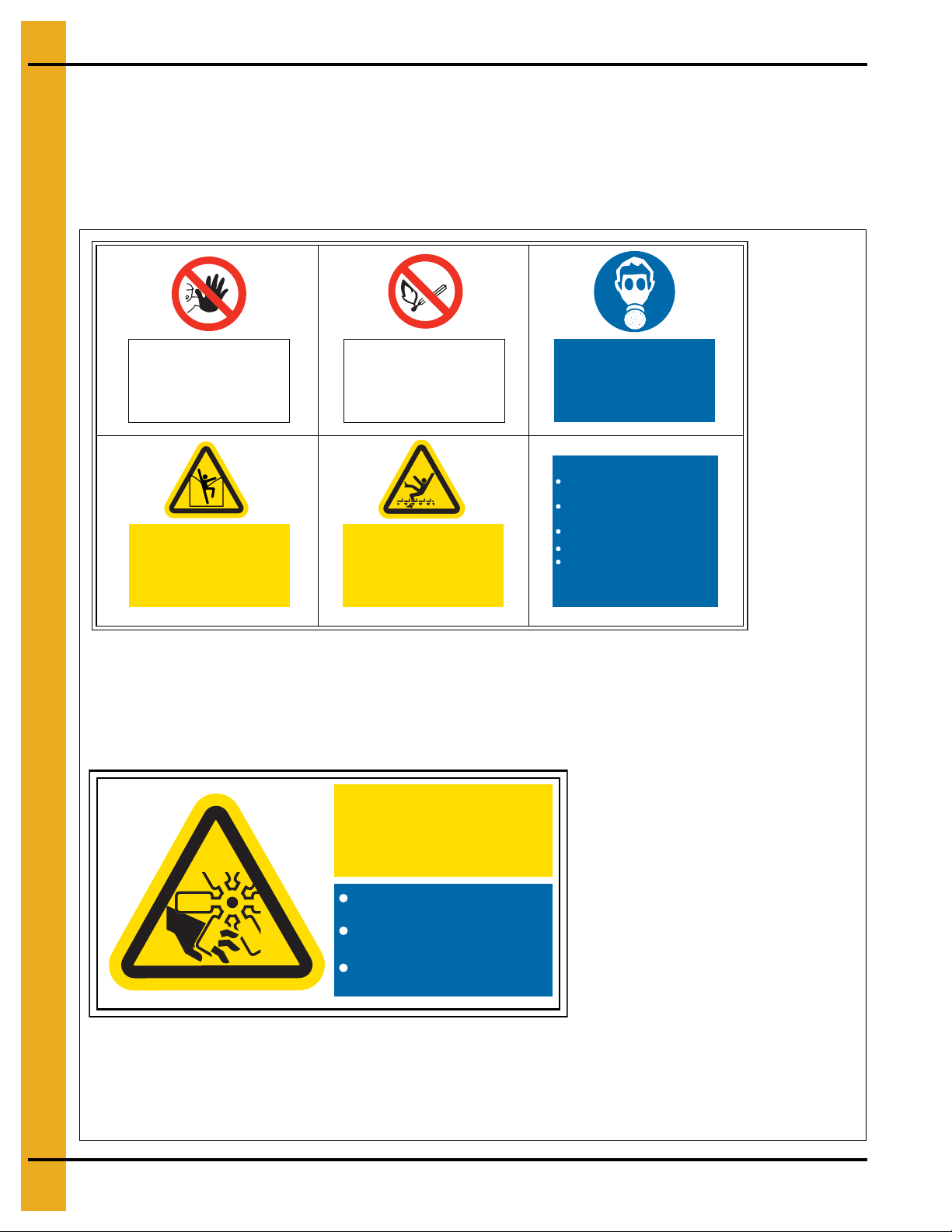
2. Decals
Respirators
must be worn
in this area
No entry to
unauthorised
personnel
DC-2161
Isolate and lock all power
before entering this bin
Do not walk directly
on stored material
Before entering:
Disconnect and lock all electrical
power
Use safety harness and safety line
Ensure someone else is outside
the bin
Disconnect and lock fuel supply
Permit required for entry into
confined space
Suffocation and
Entrapment Hazard
Automatic Machinery
No smoking or
naked flames
DC-2161
Background: White
Colors: Black, ANSI Yellow, ANSI Blue and ANSI Red
Size: 8.860" x 5.910"
Do not operate with guards
removed
Isolate and lock from power
before removing guards
Replace all guards before
reconnection to power
Automatic
Rotating
Fan Blades
DC-2162
DC-2162
Background: White
Colors: Black, ANSI Yellow and ANSI Blue
Size: 3.940" x 1.970"
Safety decals must be read and understood by all people in and around the top dry area. If any safety
decals are not displayed on the top dry or if they are damaged, contact the GSI Group, Inc. for replace ment:
Decals
1004 E. Illinois St.
Assumption, IL. 62510
Phone: 1-217-226-4421
8 PNEG-1820 CE Compliant Top Dry Series 2000 Autoflow
Page 9
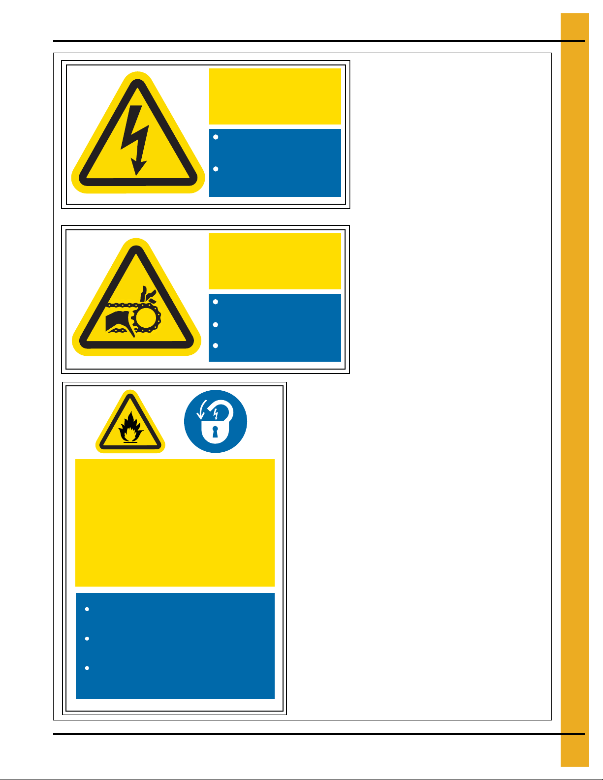
Isolate and lock from power
before removing guards or
opening enclosure
Replace all guards and lock
enclosure before reconnecting
to power
High
Voltage
DC-2163
DC-2163
Background: White
Colors: Black, ANSI Yellow and ANSI Blue
Size: 3.940" x 1.970"
Automatic
DC-2164
Background: White
Colors: Black, ANSI Yellow and ANSI Blue
Size: 3.940" x 1.970"
DC-2165
Do not open door while drier is
running
Disconnect and lock electric and
gas supply before opening
Close and lock door before
reconnecting
High Temperature
and Pressure
Equipment Can Start
Unexpectedly
DC-2165
Background: White
Colors: Black, ANSI Yellow and ANSI Blue
Size: 5.910" x 3.940"
Machinery
Do not operate with guards
removed
Isolate and lock from power
before removing guards
Replace all guards before
reconnection to power
DC-2164
2. Decals
PNEG-1820 CE Compliant Top Dry Series 2000 Autoflow 9
Page 10
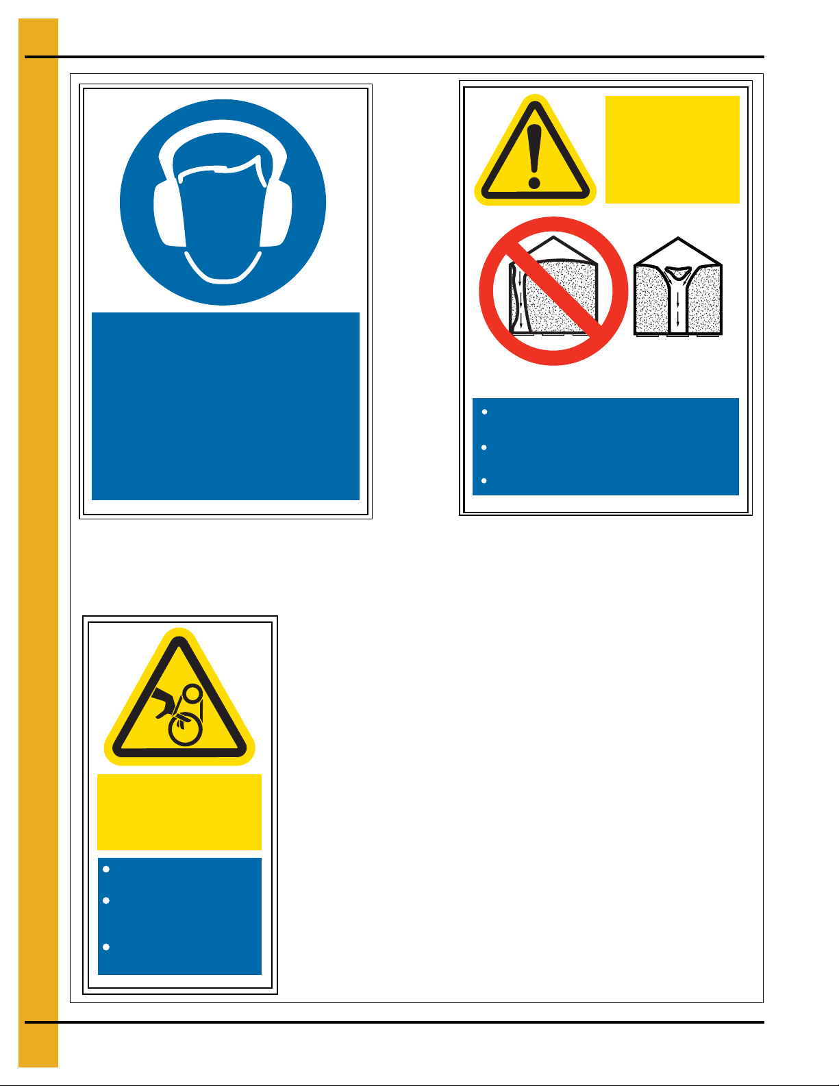
2. Decals
DC-2166
Ear protection
must be worn
in this area
DC-2166
Background: White
Colors: Black and ANSI Blue
Size: 5.910" x 3.940"
NO YES
Use CENTRE OUTLET ONLY until NO
grain remains above the outlet
Failure to follow
these instructions
will result in
structural damage
or collapse
Side outlets to be used ONLY when this
condition is satisfied
Lock all side outlets to prevent incorrect use
DC-2210
DC-2210
Background: White
Colors: Black, ANSI Yellow, ANSI Blue and ANSI Red
Size: 5.910" x 3.940"
Automatic Machinery
May Start
Unexpectedly
Replace all guards before
reconnection to power
Isolate and lock from
power before removing
guards
Do not operate with
guards removed
DC-2211
DC-2211
Background: White
Colors: Black, ANSI Yellow and ANSI Blue
Size: 3.940" x 1.970"
10 PNEG-1820 CE Compliant Top Dry Series 2000 Autoflow
Page 11
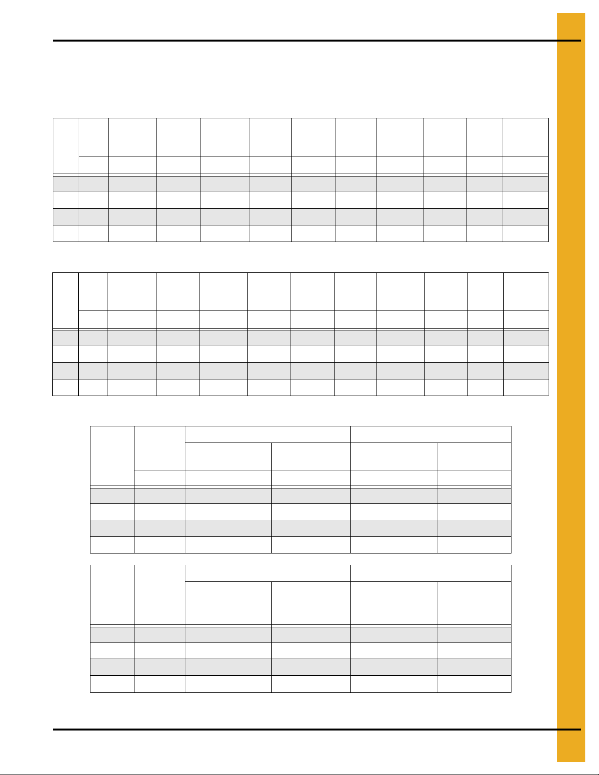
Top Dry CE Heater Specifications
Fuel Specifications
3. Fuel and Electrical Specifications
LPG Gross CV = 98.37 MJ/m
kW
kW
Maximum
Air
3
/s m3/s
m
Maximum
Air
3
/s m3/s
m
Motor
Fan
36" 11.19 8.74 2.83 747.30 373.65 1311.91 495.30 420.00 16.00 9.74 50.31
40" 11.19 12.75 5.20 747.30 373.65 1786.16 674.19 420.00 16.00 11.37 68.50
42" 22.00 16.06 7.79 871.85 373.65 2635.04 994.10 420.00 28.00 13.80 101.06
42" 30.00 17.95 8.50 871.85 373.65 3119.11 1 177.21 420.00 28.00 15.02 119.62
Natural Gross CV = 38.6 MJ/m
Motor
Fan
36" 11.19 10.39 3.31 747.30 373.65 1311.91 495.30 420.00 16.00 12.04 122.26
40" 1 1.19 12.75 5.20 747.30 373.65 1786.16 674.19 420.00 21.00 14.05 166.46
42" 22.00 16.06 7.79 871.85 373.65 2635.04 994.10 420.00 28.00 17.06 245.56
42" 30.00 17.95 8.50 871.85 373.65 31 19.11 1177.21 420.00 27.00 18.56 290.68
3
Minimum
Air
3
Minimum
Air
Maximum
Static
Pa Pa kW kW mBar mBar mm
Maximum
Static
Pa Pa kW kW mBar mBar mm
Minimum
Static
Minimum
Static
Maximum
Heat
Maximum
Heat
Minimum
Heat
Minimum
Heat
Maximum
Burner
Pressure
Maximum
Burner
Pressure
Minimum
Burner
Pressure
Minimum
Burner
Pressure
Orifice
I.D.
Orifice
I.D.
Maximum
Gas
Flow
m3/h
Maximum
Gas
Flow
m3/h
Electrical Specifications
380 VAC 400 VAC
Fan
Motor
kW A A A A
36" 11.19 22.67 68.01 21.54 64.61
40" 11.19 22.67 68.01 21.54 64.61
42" 22.00 44.57 133.70 42.34 127.02
42" 30.00 60.77 182.32 57.74 173.21
Motor
Fan
kW A A A A
36" 11.19 22.67 68.01 21.54 64.61
40" 11.19 22.67 68.01 21.54 64.61
42" 22.00 44.57 133.70 42.34 127.02
42" 30.00 60.77 182.32 57.74 173.21
Maximum Current
Draw FLA
415 VAC 440 VAC
Maximum Current
Draw FLA
Maximum Start
Current
Maximum Start
Current
Maximum Current
Draw FLA
Maximum Current
Draw FLA
Maximum Start
Current
Maximum Start
Current
NOTE: When commissioning, check motor ratings on individual motors and set overloads accordingly.
PNEG-1820 CE Compliant Top Dry Series 2000 Autoflow 11
Page 12

4. Electrical Installation
The electrical supply must be capable of the full demand from the dryer, including aeration fan, fill and
empty equipment and start currents.
All CE Top Dry fans are star delta starting.
Refer to electrical specifications Table on Page 11 for minimum current demand per fan heater.
For twin fan units, double the minimum demand.
Allow for fill and empty equipment loads.
Power supply to the dryer must include a suitable, lockable supply disconnect switch (isolator).
Machine to Earth Connection
The dryer must be connected to earth.
In most cases this will be via the earth supply provided with the power supply.
Where no earth is supplied or for generator supplies, a ground rod must be used. This must be selected
and installed by a qualified engineer, in accordance with EU Directives and/or Local Regulations
and Codes.
Emergency Stop
The dryer is fitted with an emergency stop.
It is recommended that auxiliary fill and empty equipment be installed so that in the event of an emergency
stop, all equipment is stopped.
This is the responsibility of the installer.
The dryer is supplied with a door safety switch. This must be connected to the required terminals so that
the dryer is stopped if the door is opened.
12 PNEG-1820 CE Compliant Top Dry Series 2000 Autoflow
Page 13

5. Fuel Installation
Fuel Supply
The dryer requires a suitable fuel supply. Refer to fuel specifications Table on Page 11 for fuel
flow requirements.
Liquid LPG
Dryers with internal vaporizers require LPG in liquid form.
Vapor LPG
Dryers without internal vaporizers require LPG in vapor form.
LPG tanks must have adequate vaporizing capacity to supply the maximum fuel flow given in
fuel specifications Table on Page 11. Alternatively and external vaporizer may be used.
For twin fan units, double the fuel flow.
Primary pressure regulation is required at the tank, including over pressure protection.
Supply pressure at the dryer should be 1.5 bar-2.0 bar (150 kPa-200 kPa).
Natural Gas
Natural gas dryers require a supply capable of the maximum flow given in fuel specifications
Table on Page 11.
For twin fan units, double the flow.
Minimum supply pressure at the dryer must be 750 mBar (75 kPa).
Primary pressure regulation should include over pressure protection.
PNEG-1820 CE Compliant Top Dry Series 2000 Autoflow 13
Page 14

6. Control Panel
Dryer Control Panel
Figure 6A
Moisture Control Switch
Determines if the grain temperature set point is used in the operation of the dryer.
When “ON” position, the grain will be dumped when it reaches the temperature set point and the dry timer
has reached zero.
When “ON” the switch is lit when the grain is below set point.
Control Power Switch
Turns ON/OFF power to the electronic monitoring control system.
Aeration Fan Switch
Controls the operation of the aeration fan located at the bottom of the bin.
AUTO = Fan runs only with the main drying fans.
ON = Fan comes on when the dryer is running.
14 PNEG-1820 CE Compliant Top Dry Series 2000 Autoflow
Page 15

6. Control Panel
Load Auger Switch
Controls the operation of the drying chamber fill system(s).
Switch is lit when the fill system(s) are running.
AUTO = Fill system(s) start and stop automatically depending level of grain in drying chamber. When
operating in the Autobatch mode the fill system(s) will shut off 2/3 of the way through the dry
cycle regardless of drying chamber level.
ON = Fill system(s) are ON when the dryer is running.
Fan Switch
Controls the operation of the main drying fan(s).
Switch is lit when airflow is sensed.
AUTO = Main drying fan(s) start when drying chamber is full.
ON = Main drying fan(s) come ON and stay ON when the dryer is running.
Heater Switch
Controls the operation of the burner(s).
Switch is lit when the burner is ON.
Small lights above and below the heater switch indicate if the burner(s) are in high-fire or low-fire.
AUTO = Burner(s) light when drying chamber is full remain on until the dryer shuts down or is stopped.
ON = Burner(s) light anytime the main drying fan(s) are running.
Dump Switch
Controls the operation of the drying chamber dump chutes.
Switch illuminate when the chutes are moving.
MANUAL CLOSE = Chutes close.
AUTO = Chutes automatically dump at the end of the drying cycle.
MANUAL OPEN = Chutes open (dump).
NOTE: Manual open and close only operate when the dryer Stop button has been pressed.
Dry and Hold Switch
When ON the normal dump cycle will be inhibited at the end of the dry cycle.
Dryer Power Start Switch
Starts the dryer.
Lit up when dryer is running.
Dryer Power Stop Switch
Stop the dryer.
Also used to reset after an error or fault.
PNEG-1820 CE Compliant Top Dry Series 2000 Autoflow 15
Page 16

7. Control System
Electronic Monitoring Control System
Figure 7A
Electronic Monitoring Control System
This controls all timing functions and safety circuits. It provides printed messages and warnings.
Turn control power to “ON” to start the control. The control will enter the main drying screen.
Setting the Dry, Cool and Unload Timers
These set the dry, cool and dump cycle times. The timer settings are displayed above the Timer button.
To alter the setting:
1. Press the Dry, Cool or Unload Timer button.
2. Press “modify”.
3. Press “increase” or “decrease” to adjust the settings.
4. Press “enter”.
5. To enter the new value into memory, press “reset”.
During drying the remaining time for each timer is displayed. The control retains these values in the even t
of a power failure. Pressing “reset” returns the timers to their initial setting. The cool timer is not used in
an Autoflow system.
16 PNEG-1820 CE Compliant Top Dry Series 2000 Autoflow
Page 17

7. Control System
Setting the Delays
The following timers are set using the same procedure, but the Rese t button does not need to be pressed
to enter the new values into memory immediately.
AUX. 1 DELAY - Not used.
REFILL DELAY - Used only on batch units. This delays the start of drying to allow the drying chamber to
fill. If the unit does not refill within this time the unit will give a “dry chamber empty” error.
FILL #1 DELAY - This timer keeps the fill system running for a period of time after the Drying Chamber
switch has detected grain. The purpose is to eliminate rapid start/stop in the fill system. Set the timer so
that grain covers the Upper Level switch, but does not reach the Chamber Overflow switch.
If the Autoflow controls two (2) fill systems, this timer keeps fill system #1 running after fill system #2 has
stopped. (Fill system #1 is the system the delivers direct to the drying chamber.) Set the time to completely
empty fill system #1, but should not allow grain to reach the Chamber Overflow switch.
FILL #2 DELAY - This timer is used where two (2) fill systems are controlled. It ke eps fill system #2 running
for a period of timer after the Drying Chamber Upper Level switch has detected grain. Set the timer so that
grain covers the Upper Level switch, but does not reach the Chamber Overflow switch.
OUT OF GRAIN DELAY - This allows the dryer to continue running for a period of time after the Drying
Chamber Low Level switch has detected no grain. This stops nuisance shut downs. Once the out of grain
timer has elapsed the dryer will shut down and report “no grain”. If you are getting “no grain” shut down s,
increase the timer.
FAN DELAY - Used only on twin fan units to delay the start of the second (slave) fan. Recommended
setting is 3 seconds.
FANS OFF DELAY - Allows the fans to be stopped during the dump cycle. Options are 1.00 (ON) and
0.00 (OFF). When ON the fans will stop during the dump cycle and restart following.
Standard Setup
The setup mode is used to program the computer with different variables that influence how the dryer
will operate.
CLEAR TOTAL BATCHES - Press the Reset button to clear the total batches. Press the Enter button
to continue.
CLEAR WARNING HISTORY - Press the Reset button to clear the warning history. Press the Enter button
to continue.
TIME UNTIL LOAD OFF - In Autobatch mode is the percentage of time through the dry cycle that the fill
systems will be shut off regardless if the dryer is full or not. Press the Enter button to return to the main
drying screen.
Extended Setup
SET DATE SET MONTH SET YEAR SET HOUR SET MINUTE -
PNEG-1820 CE Compliant Top Dry Series 2000 Autoflow 17
Page 18

7. Control System
Use the Increase and Decrease buttons to select the correct time or date. Press the Enter b utton to accept.
LOW LEVEL TEST MODE - Use the Increase and Decrease buttons to enable or disable Drying Chamber
Low Level switch monitoring.
WET TANK TEST MODE - Use the Increase and Decrease buttons to enabled or disabled wet supply
level switch monitoring.
START FANS WITH HIGH - Use the Increase and Decrease buttons to enable or disable fan starting
based on the Upper Drying Chamber Level switch. Recommended practice is fans starting with the Drying
Chamber Low Level switch.
AERATION FAN BYPASS - Use the Increase and Decrease buttons to enabled or disabled. When
enabled the fan runs after the dryer stops.
# OF FILL SYSTEMS - Use the Increase and Decrease buttons to select one or two (2) fill systems under
dryer control. Note setting of fill #1 and fill #2 system timers on Page 19.
SELECT DRYER TYPE - Use the increase and decrease select dryer model:
AF3 - Three (3) drying fan Autoflow.
AF2 - Two (2) drying fan Autoflow.
AF1 - Single drying fan Autoflow.
AB3 - Three (3) drying fan Autobatch.
AB2 - Two (2) drying fan Autobatch.
AB1 - Single drying fan Autobatch.
SELECT TEMP SCALE - Use the increase and decrease to select Fahrenheit or Celsius.
MODEM INIT STRING - Not used. Press the Enter button to return to the main drying screen.
BURNER DIFFENTIAL - Use the Increase and Decrease buttons to change temperature difference
between high-fire and low-fire. Recommended setting 3°C.
Help
Currently not used.
Plenum
Set target plenum temperature.
Grain
Set target grain temperature with Increase/Decrease buttons.
Screens
By pressing the Screens button, you can toggle between two (2) screens. Screen #1 displays the current
plenum and grain temperatures and their set points in parenthesis. Screen #2 displays the status of the
Drying Chamber Rotary switches and the total number of batches. In all screens the dry time and dump
time are displayed at the bottom of the screen.
18 PNEG-1820 CE Compliant Top Dry Series 2000 Autoflow
Page 19

8. Fill System Control Box
Figure 8A
The fill system control box houses the motor starters for fill system #1, fill system #2 and the aeration fan.
Switches are located on the front of the fill system control box and an Emergency Stop switch is located
on the side of the control box.
Fill system #1 and fill system #2:
0 = OFF
1 = Manual ON
AUTO = Operates under dryer control
Aeration fan:
0 = OFF
1 = Manual ON
AUTO = Operates under dryer control
Emergency Stop switch:
This switch will stop the dryer when pushed and should be used in case of emergency.
PNEG-1820 CE Compliant Top Dry Series 2000 Autoflow 19
Page 20

8. Fill System Control Box
Flame probe
Ignitor
9
10
3
1
2
4
6
7
8
5
Flame probe
Ignitor
Vaporizer
Figure 8B Ignitor and Flame Probe Assemblies
20 PNEG-1820 CE Compliant Top Dry Series 2000 Autoflow
Page 21

8. Fill System Control Box
Loosen this bolt to
adjust the vaporizer coil.
Loosen this bolt to
adjust the vaporizer coil.
Flame Probe, Ignitor and Burner Assemblies Parts List
Ref # Description
1-3 Flame Probe Assembly Network
1 Boot 8 mm Silicone 90°
2 Flame Sensor 6" Long Rod
3 Flame Sensor Bracket
4-8 Ignitor Assembly
4 Dual Probe Ignitor Bracket
5 Ignitor Air Deflector Angle
6 Ignitor Half Clamp
7 Ignitor Flame
8 Ignition Wire Assembly (Includes Both Wires)
9 Cone
10 Vaporizer Coil
PNEG-1820 CE Compliant Top Dry Series 2000 Autoflow 21
Figure 8C LP Vaporizer Coil Adjustment
Page 22

9. Error Messages and Valve Proving System
Error Messages
Burner * Loss Flame
The flame sensor in burner number * has failed to detect flame. Possible causes:
Burner failed to light.
1. Check fuel supply and pressure.
2. Check spark.
3. Check all solenoid valves are opening.
Flame sensor needs adjusting.
1. It must be in the flame.
2. It can be bent gently if required.
Fan * Vapor High-Limit
The LP gas vapor temperature has exceeded 109°C causing the high-limit to open. This will reset when
cool. The vaporizer must be adjusted to move it further from the flame to prevent this re-occurring.
Fan * Housing High-Limit
The temperature in the fan/heater housing has exceeded 109°C. Housing high-limit must be
manually reset.
Plenum High-Limit
The dryer plenum has gone over temperature. The plenum high-limit resets automatically when cooled.
The low-fire gas pressure needs to be lowered or the cycle set poin t on the high-low thermostat needs to
be increased if the error is displayed frequently.
NOTE: Vapor, plenum and housing high-limit errors will cause the burner control to lock out. This can only
be reset by pressing the illuminated Reset button on the burner control.
Fan * Motor Overload
The thermal overload in the control box on fan number one has tripped, indicating an over current
condition. The overload must be reset manually.
Fan * Loss of Airflow
The burner control air switch is not sensing adequate airflow to allow the burner to light.
1. Check fan is operating at correct speed.
2. Check for damaged fan blades.
3. Check air inlet is not impeded.
4. Check pressure switch.
5. Adjust pressure switch.
22 PNEG-1820 CE Compliant Top Dry Series 2000 Autoflow
Page 23

9. Error Messages and Valve Proving System
Drying Chamber Overflow
The grain level in the drying chamber has reached the Drying Chamber Overflow Rotary switch. Grain will
have to be dumped from the drying chamber to the storage chamber before the unit can be re-started. This
error indicates that either the drying chamber High Level Rotary switch is faulty or the time on the load
delay or Aux. 1 delay needs to be lowered.
Bin Grain High-Limit Full
The grain level in the storage chamber has reached the storage chamber High Level Rotary switch located
1 m below the fan and heater(s). Grain will have to be removed from the storage chamber before the unit
can be re-started.
Bin High-Limit Switch Bad
The Storage Chamber High Level switch has failed. Switch must be repaired or replaced.
Out of Grain
The grain in the wet supply tank has fallen below the Wet Supply Rotary switch. If there is grain against
the Drying Chamber Low Level Rotary switch the dryer can be re-started by pressing the Stop switch to
clear the error and then the Start switch.
Wet Supply Empty Press <Enter> to Dry Remaining Grain
The Start button is pushed and grain is below the Wet Supply Level switch whilst grain remains in the
Drying Chamber Low Level Rotary switch. If the Enter button is pushed the dryer will re-start, but the fill
system(s) will not re-start.
Cannot Start Dryer Wet Supply Empty
The Start button is pushed and grain below the Wet Supply Level switch and there is no grain in the
drying chamber.
Dry Chamber Empty
The grain is below the drying chamber low level switch and the Aux. 1 timer has reached zero. If the
error is being caused due to the settling of grain after the fans start the time on the Aux. 1 timer can
be lengthened.
Fill * Motor Overload
The thermal overload for fill system number * has tripped, indicating an over current condition. The
overload must be reset manually.
Aeration Overload
The thermal overload for the aeration fan has tripped, indicating an over current condition. The overload
must be reset manually.
PNEG-1820 CE Compliant Top Dry Series 2000 Autoflow 23
Page 24

9. Error Messages and Valve Proving System
High gas pressure switch
Valve proving system
Low-fire adjustment screw
High-low valve
Grain High-Limit
The grain temperature in the drying chamber is too high.
Valve Proving System
The main safety shut-off valve is fitted with a proving system which will prevent burner start-up if the valve
is leaky.
Figure 9A
Check the light status on the VPS. Red light indicates leaky valve. VPS is reset by pressing the
Reset button.
High Gas Pressure Switch
In addition to the high pressure relief, the main solenoid valve is fitted with a High Pressure switch. This
will cause the burner to shut down if the pressure exceeds the pre-set level.
24 PNEG-1820 CE Compliant Top Dry Series 2000 Autoflow
Page 25

10. Initial Start-Up
Dryer Commissioning
Electrical
1. Carry out earth bonding test per EN60204 and/or local electrical laws and regulations.
2. Check adequate power supply. (Refer to electrical specifications Table on Page 11.)
3. Voltage at phases must be within 5% of rated voltage.
4. Voltage drop must not exceed 5% when under full load.
5. Check overload settings for each motor circuit.
6. Complete full electrical tests in accordance with EU Directives and local laws, regulations and codes.
Gas Train
1. Pressure test.
• Close inlet valve.
• Close firing valve.
• Fit pressure test nipple into main solenoid inlet flange.
• Attach hand bellows and pressure gauge.
• Pressurise gas train with air to 35 kPa (350 mBar).
• Check for pressure loss at gauge.
• Use leak detection to test for leaks.
2. Set inlet pressure per fuel specifications Table on Page 11.
3. Set relief valve to open at 550 mBar (55 kPa).
• Apply air pressure via main solenoid inlet flange.
• Increase/decrease spring pressure in relief valve.
• Valve should open at 55 kPa maximum.
4. Set over High Pressure switch to 500 mBar.
5. Set burner high fire pressure.
• Note required high fire pressure from fuel specifications Table on Page 11.
• Set plenum temperature to approx. 100°C above ambient.
• Light burners.
• Check high-low valve is fully open.
• Read pressure at burner gauge.
• Adjust pressure a regulator to give required pressure.
• Lock regulator.
PNEG-1820 CE Compliant Top Dry Series 2000 Autoflow 25
Page 26

10. Initial Start-Up
Gas Train (Continued)
6. Set burner low-fire pressure.
• Set plenum temperature to approx. 10°C above ambient.
• Light burners.
• On low fire, adjust high-low valve minimum setting to give pressure as per fuel specifications
Table on Page 11.
7. Read pressure at burner gauge. (See Figure 9A on Page 24.)
8. Run burners and check burner modulates correctly.
9. Check gas pressure remains stable fill out gas train commissioning check sheet.
26 PNEG-1820 CE Compliant Top Dry Series 2000 Autoflow
Page 27

11. Pre-Season Checks
Before the dryer is filled, inspect the unit and check the operation of the dryer as follows. Never enter a
bin where grain is present.
Set Control Switches
• Moisture Control switch - “ON”
• Aeration Fan switch - “OFF”
• Load Auger switch - “OFF”
• Fan switch - “OFF”
• Heater switch - “OFF”
• Dump switch - “AUTO”
• Dry and Hold switch - “OFF”
• Autoflow Emergency Stop switch - “OUT”
• Actuator switch - “ON”
• Fill System Control Box Emergency Stop switch - “OUT”
Control Power Switch
Turn the control power switch ON. The switch will illuminate. If a fault is found an error message will be
displayed on the screen. If all are found safe, the main drying screen will be displayed.
Figure 11A Top Dry Component Placement
PNEG-1820 CE Compliant Top Dry Series 2000 Autoflow 27
Page 28

11. Pre-Season Checks
Drying Chamber
Inspect each dump hopper for obstructions.
Make sure that the gap between the discharge flow plates and the floor sheets is a minimum of 38 mm.
Rotary Switches
Check all rotary switches are spinning freely.
Linear Actuator
Turn the Dump switch “manual open”.
Check the stroke on the actuator is 300 mm to 350 mm. Adjust if necessary.
Make sure that all pulleys and cables move freely.
With the actuator extended, view each dump chute to make sure they are completely open.
The dump chutes should hinge smoothly.
Turn Dump switch to “AUTO” position and press the Stop switch. The chutes should raise.
Power Start Button
Ensure there is grain in the wet supply tank.
Push the dryer Start button. The screen should no longer flash “STOPPED”.
Fuel Check
Check for leaks as described previously.
Fan
Check fan rotates freely and in the correct direction. (See fan direction decal on Page 8.) If required
reverse the fan by swapping over phases L1 and L3.
Make sure the fan runs smoothly with no vibration.
Aeration Fan
Check fan rotates freely and in the correct direction. (See fan direction decal on Page 8.) If required
reverse the fan by swapping over phases L1 and L3.
Make sure the fan runs smoothly with no vibration.
28 PNEG-1820 CE Compliant Top Dry Series 2000 Autoflow
Page 29

11. Pre-Season Checks
Fill System
Prepare the wet storage tank to deliver grain to the dryer.
Make sure all personnel clear.
Switch load auger to “AUTO”.
Grain should be delivered from the wet supply tank to the dryer.
When the display shows “GRAIN LOW LEVEL YES” close the valve that supplies the fill system(s) with
wet grain from the wet supply tank.
When the load auger empties turn it “OFF”.
Air Switch
With the drying fan running, adjust the air switch so that it just stops sensing airflow, then increase the
air switch sensitivity by 1 full turn.
Figure 11B Air Switch Adjustment
Repeat on the slave unit for 2 fan dryers.
Burner Test Fire
Check burner operation and high-low firing rates as per on Page 25.
Note, the burner control runs a fixed purge period of 35 seconds before the burner lights.
Dryer Shut Down
For long term shut down, allow the burner to burn out by shutting off the fuel whilst burning.
Press Stop.
Emergency
In case of an emergency, push the Emergency Stop switch located on the side of the Auto flow control box
and the fill system control box.
PNEG-1820 CE Compliant Top Dry Series 2000 Autoflow 29
Page 30

12. Autoflow Theory
Top Dry Autoflow Theory of Operation
Control Panel Switch Status
• Control power: “ON”
• Moisture control thermostat: “ON”
• Aeration fan: “AUTO”
• Load auger: “AUTO”
• Fan: “AUTO”
• Heater: “AUTO”
•Dump: “AUTO”
• Dry and hold: “OFF”
Emergency Stop Switch Status
• Autoflow control box emergency stop: “pulled out”
• Fill system control box emergency stop: “pulled out”
• Actuator co ntrol box 24V switch: “ON”
• Aeration fan bypass: “enabled”
With no grain in the drying chamber and wet grain in the wet storage tank, fill system #1 and fill system #2
(if fitted) will start.
When grain reaches the Drying Chamber Low Level switch, the aeration fan and the master drying fan
will start.
After the fan delay time the slave drying fan (if fitted) will start, the air switch will close and the dry timer
will start to count down.
After a 20 seconds purge delay, the fan/heater unit(s) will ignite.
When the plenum temperature reaches the cycle set point, the fan/heater unit(s) will cycle to low-fire.
The fan/heater units will continue to cycle throughout the drying process.
When grain reaches the Chamber High Level switch, the fill #2 delay will begin to count down.
When the fill #2 delay reaches zero, fill system #2 will shut off and the fill #1 delay will begin to count down.
When the fill #1 delay reaches zero fill system #1 will shut off.
If the grain drops below the High Level switch, the fill system(s) will start and refill the drying chamber.
When the dry timer reaches zero, if the grain temperature is below set point, the dryer will go into
temperature hold.
When the grain temperature reaches set point, the unit will continue to the dump cycle.
In the dump cycle, the grain is dumped into the storage chamber.
When the dump timer reaches zero, the dump chutes raise.
30 PNEG-1820 CE Compliant Top Dry Series 2000 Autoflow
Page 31

12. Autoflow Theory
During the dump cycle 1/3 of the grain is dumped into the storage chamber.
After the dump cycle, the unit returns to the beginning of the dry cycle, the fill system(s) refill the drying
chamber and the process begins again.
The unit continues with the same operation until either no grain is present agai nst the Wet Supply Rot ary
switch or the storage chamber becomes full.
If the wet storage tank becomes empty, the fill #1 and fill #2 delays starts to count down.
When the delays reach zero, the fill system(s) and dryer shut off.
Wet supply hopper empty “out of grain” error is displayed. If there is grain above the Drying Chamber Low
Level switch, the unit can be re-started by pressing the Start switch.
When the Start switch is pressed, the screen on the dryer control panel will read “press enter to dry
remaining grain”. If the Enter button is pushed the dryer will re-start without running the fill system(s). The
dryer will remain running until the completion of the next dump cycle, af ter which an “out of g rain” error is
displayed on the dryer control panel and the dryer stops.
If the storage chamber reaches full during the dump cycle, the dryer will continue through the dump cycle
and will continue to the next dry cycle.
When the dry cycle is complete, the unit will not continue to the dump cycle. A “bin grain high-limit” error
will be displayed on the screen and the dryer will stop.
If the dryer stops for any reason, the aeration fan will remain running if the aeration fan bypass is enabled.
PNEG-1820 CE Compliant Top Dry Series 2000 Autoflow 31
Page 32

13. Start-Up Procedure
Initial Dryer Start-Up
1. With Control Power switch OFF, turn ON the main power supply.
2. Pull out all Emergency Stop switches.
3. Set the switches as follows:
• Moisture Control switch - “ON”
• Aeration Fan switch - “AUTO”
• Load Auger switch - “OFF”
• Fan switch - “AUTO”
• Heater switch - “AUTO”
• Dump switch - “AUTO”
• Dry and Hold switch - “OFF”
4. Make sure there is wet grain in the wet supply tank.
5. Turn control power “ON” position.
6. The screen will display a copyright message and software version number.
7. The screen should read “STOPPED”. The chamber high level and the chamber low level should both
read “NO”.
8. Set the dry timer using the drying charts for the specific bin size, fan and heater size, drying
temperature and grain input moisture content.
9. Set the dump timer as follows:
• 18' Diameter bin = 30 Seconds
• 21' Diameter bin = 33 Seconds
• 24' Diameter bin = 36 Seconds
• 27' Diameter bin = 39 Seconds
• 30' Diameter bin = 42 Seconds
• 36' Diameter bin = 36 Seconds
10. Set all other delays and timers as prescribed in the electronic monitoring control section on Page 16
of this manual.
11. Press the Reset button for timer changes to take effect immediately.
32 PNEG-1820 CE Compliant Top Dry Series 2000 Autoflow
Page 33

13. Start-Up Procedure
CAUTION
Be sure all personnel are clear of fill systems. Place the Load Auger switch on the
dryer control panel to the “AUTO” position.
12. Set the grain temperature set point as follows:
• 82°C Drying temperature = 38°C Grain temperature set point
• 77°C Drying temperature = 39°C Grain temperature set point
• 71°C Drying temperature = 41°C Grain temperature set point
• 66°C Drying temperature = 42°C Grain temperature set point
• * 60°C Drying temperature = 43°C Grain temperature set point
• * 54°C Drying temperature = 45°C Grain temperature set point
• * 49°C Drying temperature = 46°C Grain temperature set point
* When drying at a temperature lower than 66°C the grain temperature set point on the moisture
control thermostat may require a lower setting at right.
13. Press the Start switch on the dryer control panel.
14. The fill system(s) should start immediately.
15. When the grain reaches the Drying Chamber Low Level switch, the fan and heater(s) should start.
16. When the grain reaches the drying chamber, Low Level Rotary switch reaches the Drying Chamber
High Level Rotary switch the fill system(s) should stop.
17. When the dry timer reaches zero, the display should read “TEMP HOLD”.
18. When the grain temperature reaches the grain temperature set point, the dryer should continue to
the dump cycle.
19. The dump chutes should lower, grain should dump from the drying chamber into the storage chamber
and the fill system(s) should start.
20. After the dump cycle, the dryer should continue to the beginning of the next dry cycle.
21. After the fourth dump, stop the dryer.
22. Test the moisture of the dried grain.
23. If the moisture of the grain is too high, increase the grain temperature set point 2.5°C for each
additional point of moisture to be removed.
24. If the moisture of the grain is too low, decrease the grain temperature set point 2.5°C for each
additional point of moisture to be added.
25. After the moisture control thermostat is adjusted, decrease the time on the dry timer by one-half.
The dry timer should not be set lower than the amount of time it takes the dryer to refill after the
dump cycle.
26. Re-start the dryer. The time on the dry timer should expire before the grain reaches the
temperature set point.
27. Any time a change is made to the grain temperature set point, the dryer must dump four (4) times
before the full effect of the change will be made on the moisture of the grain.
PNEG-1820 CE Compliant Top Dry Series 2000 Autoflow 33
Page 34

13. Start-Up Procedure
Normal Start-Up
When the dryer is started with grain in the drying chamber that has already been partially dried, the drye r
can be started without making any adjustments to time or temperature; however, the moisture of the grain
should be checked after the fourth dump.
Last Fill
1. Stop the dryer when all the wet grain has been loaded into the drying chamber and turn OFF the
Moisture Control switch.
2. Set the time on the dry timer for twice the recommended amount using the charts for the specific bin
size, fan and heater size, drying temperature and grain input moisture content.
3. Push the Reset button.
4. Turn the Dry and Hold switch to the “ON” position.
5. Turn the Load Auger switch to the “OFF” position.
6. Press the Start switch.
7. When the dryer shuts down install the fan inlet cover(s).
8. Let the aeration fan cool in the top and store or manually dump into the storage chamber.
34 PNEG-1820 CE Compliant Top Dry Series 2000 Autoflow
Page 35

14. Warranty
9101239_1_CR_rev7.DOC (revised July 2009)
GSI Group, LLC Limited Warranty
The GSI Group, LLC (“GSI”) warrants products which it manufactures to be free of defects in materials and workmanship
under normal usage and conditions for a period of 12 months after sale to the original end-user or if a foreign sale,
14 months from arrival at port of discharge, whichever is earlier. The end-user’s sole remedy (and GSI’s only obligation)
is to repair or replace, at GSI’s option and expense, products that in GSI’s judgment, contain a material defect in materials
or workmanship. Expenses incurred by or on behalf of the end-user without prior written authorization from the GSI
Warranty Group shall be the sole responsibility of the end-user.
Warranty Extensions:
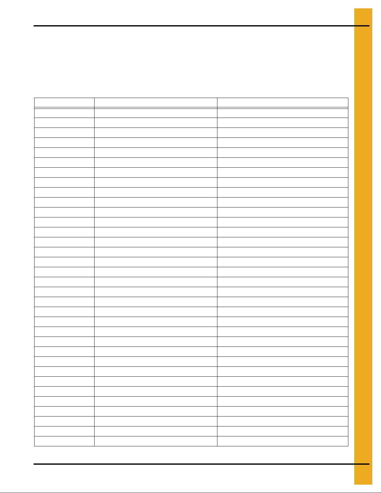
The Limited Warranty period is extended for the following products:
Product Warranty Period
Performer Series Direct Drive Fan Motor 3 Years
AP Fans and Flooring
Cumberland
Feeding/Watering
Systems
Grain Systems Grain Bin Structural Design 5 Years
Grain Systems
Farm Fans
Zimmerman
All Fiberglass Housings Lifetime
All Fiberglass Propellers Lifetime
Feeder System Pan Assemblies 5 Years **
Feed Tubes (1-3/4" and 2.00") 10 Years *
Centerless Augers 10 Years *
Watering Nipples 10 Years *
Portable and Tower Dryers 2 Years
Portable and Tower Dryer Frames and
Internal Infrastructure †
5 Years
* Warranty prorated from list price:
0 to 3 years - no cost to end-user
3 to 5 years - end-user pays 25%
5 to 7 years - end-user pays 50%
7 to 10 years - end-user pays 75%
** Warranty prorated from list price:
0 to 3 years - no cost to end-user
3 to 5 years - end-user pays 50%
† Motors, burner components
and moving parts not included.
Portable dryer screens included.
Tower dryer screens not included.
GSI further warrants that the portable and tower dryer frame and basket, excluding all auger and auger drive components,
shall be free from defects in materials for a period of time beginning on the twelfth (12
and continuing until the sixtieth (60
th
) month from the date of purchase (extended warranty period). During the extended
th
) month from the date of purchase
warranty period, GSI will replace the frame or basket components that prove to be defective under normal conditions
of use without charge, excluding the labor, transportation, and/or shipping costs incurred in the performance of this
extended warranty.
Conditions and Limitations:
THERE ARE NO WARRANTIES THAT EXTEND BEYOND THE LIMITED WARRANTY DESCRIPTION SET FORTH
ABOVE. SPECIFICALLY, GSI MAKES NO FURTHER WARRANTY OF ANY KIND, EXPRESS OR IMPLIED,
INCLUDING, WITHOUT LIMITATION, WARRANTIES OF MERCHANTABILITY OR FITNESS FOR A PARTICULAR
PURPOSE OR USE IN CONNECTION WITH: (I) PRODUCT MANUFACTURED OR SOLD BY GSI OR (II) ANY ADVICE,
INSTRUCTION, RECOMMENDATION OR SUGGESTION PROVIDED BY AN AGENT, REPRESENTA TIVE OR
EMPLOYEE OF GSI REGARDING OR RELATED TO THE CONFIGURATION, INSTALLATION, LAYOUT, SUITABILITY
FOR A PARTICULAR PURPOSE, OR DESIGN OF SUCH PRODUCTS.
GSI shall not be liable for any direct, indirect, incidental or consequential damages, including, without limitation, loss of
anticipated profits or benefits. The sole and exclusive remedy is set forth in the Limited Warranty, which shall not exceed
the amount paid for the product purchased. This warranty is not transferable and applies only to the original end-user. GSI
shall have no obligation or responsibility for any representations or warranties made by or on behalf of any dealer, agent
or distributor.
GSI assumes no responsibility for claims resulting from construction defects or unauthorized modifications to products
which it manufactured. Modifications to products not specifically delineated in the manual accompanying the equipment at
initial sale will void the Limited Warranty.
This Limited Warranty shall not extend to products or parts which have been damaged by negligent use, misuse, alteration,
accident or which have been improperly/inadequately maintained. This Limited Warranty extends solely to products
manufactured by GSI.
Prior to installation, the end-user has the responsibility to comply with federal, state and local codes which apply to the
location and installation of products manufactured or sold by GSI.
PNEG-1820 CE Compliant Top Dry Series 2000 Autoflow 35
Page 36

This equipment shall be installed in accordance with
the current installation codes and applicable
regulations, which should be carefully followed in
all cases. Authorities having jurisdiction should be
consulted before installations are made.
Copyright © 2012 by GSI Group
Printed in the USA
GSI Group
1004 E. Illinois St.
Assumption, IL 62510-0020
Phone: 1-217-226-4421
Fax: 1-217-226-4420
www.gsiag.com
CN-203943
 Loading...