

Page 1

PNEG-1813
Electronic Distributor Control
Installation and Operation Manual
PNEG-1813
Date: 08-22-12
Page 2

2 PNEG-1813 Electronic Distributor Control
Page 3

Table of Contents
Contents
Chapter 1 Safety ..................................................................................................................................................... 4
Safety Guidelines .................................................................................................................................. 4
Safety Instructions ..................... ... .... .......................................... ... ........................................................ 5
Chapter 2 Decals .................................................................................................................................................... 7
Chapter 3 Installation ............................................................................................................................................ 8
Electronic Distributor Control Shaft Installation ..................................................................................... 8
Electronic Distributor Enclosure Installation ........................................... ............................................... 9
Junction Box Installation ........................ ... ... .... ... ... ... .... ... ... ... .... ................................................ ......... 10
Sensor Plate Angle and Proximity Sensor Bracket Installation .................. ... ... ... ................................ 11
Proximity Sensor Location and Installation ......................................................................................... 12
Proximity Sensor Adjustment .............................................................................................................. 14
Encoder and Bracket Installation ........................................................................................................ 15
Motor Mounting Bracket Installation ................................. ................................................ ................... 18
Control Motor Installation .................................................................................................................... 19
Wire and Fitting Selection Recommendations .......... .... ... ... ... .... ... ... ... ... .... ... ... ... .... ... ... ... ... .... ... ... ... ... 20
Distributor to Junction Box Electrical Connections .............................................................................. 21
Control Panel Cable to Distributor Fitting Connections ....................................................................... 22
Motor Cable to Motor Junction Box Fitting Connections ..................................... .... ... ... ... ... .... ... ... ... ... 23
Electronic Distributor Wiring Diagram ................................................................................................. 24
Motor Wiring to Motor Junction Box Electrical Connections ...................................... ... ... ... .... ... ......... 25
Control Panel Wiring to Junction Box Electrical Connections ............................................................. 26
Enclosure Covers Installation .............................................................................................................. 27
Control Panel Wiring from Motor Electrical Connections .................................................................... 28
Power Supply Wiring to Control Panel Electrical Connections ........................................................... 29
Control Panel Installation Guidelines .................................................................................................. 30
Chapter 4 Operation Procedures ........................................................................................................................ 31
Initializing Screen ...................................... ... .... ... ... .......................................... ... ................................ 31
Main Screen ........................................................................................................................................ 32
Help Menu Screen .............................................................................................................................. 33
Move Screen .................................... ... ... ....................................................................................... ... ... 35
Setup Menu Screen ............................ ... ... ... .... ... ... ... .... .......................................... ... ......................... 36
Manual Override ........................ ... .... ... .......................................... ... ............................................. ... ... 45
Chapter 5 Parts List ............................................................................................................................................. 46
12" 6 Hole 45° Distributor Assembly Electronic Control (DFB12645G-EC) ........................................ 46
Chapter 6 Troubleshooting ................................................................................................................................. 48
Error Messages ................................................................................................................................... 48
Chapter 7 Schematic and Wiring Diagrams ...................................................................................................... 51
White Panel Layout ............................................................................................................................. 51
White Panel Electrical Schematic .................................................................................................... ... 52
Chapter 8 Warranty .............................................................................................................................................. 55
PNEG-1813 Electronic Distributor Control 3
Page 4
1. Safety
This is the safety alert symbol. It is used to alert you
to potential personal injury hazards. Obey all safety
messages that follow this symbol to avoid possible
injury or death.
WARNING indicates a hazardous situation which, if not
avoided, could result in death or serious injury.
CAUTION, used with the safety alert symbol, indicates a
hazardous situation which, if not avoided, could result in
minor or moderate injury.
NOTICE is used to address practices not related to
personal injury.
DANGER indicates a hazardous situation which, if not
avoided, will result in death or serious injury.
Safety Guidelines
This manual contains information that is important for you, the owner/operator, to know and understand.
This information relates to protecting personal safety and preventing equipment problems. It is the
responsibility of the owner/operator to inform anyone operating or working in the area of this equipment
of these safety guidelines. To help you recognize this information, we use the symbols that are defined
below. Please read the manual and pay attention to these sections. Failure to read this manual and its
safety instructions is a misuse of the equipment and may lead to serious injury or death.
DANGER
WARNING
CAUTION
NOTICE
4 PNEG-1813 Electronic Distributor Control
Page 5
1. Safety
Follow Safety Instructions
Carefully read all safety messages in this manual and
safety signs on your machine. Keep signs in good
condition. Replace missing or damaged safety signs. Be
sure new equipment components and repair parts include
the current safety signs. Replacement safety signs are
available from the manufacturer.
Learn how to operate the machine and how to use controls
properly. Do not let anyone operate without instruction.
Keep your machinery in proper working condition.
Unauthorized modifications to the machine may impair
the function and/or safety and affect machine life.
If you do not understand any part of this manual or need
assistance, contact your dealer.
Read and Understand Manual
Practice Safe Maintenance
Understand service procedures before doing work. Keep area
clean and dry.
Never lubricate, service, or adjust machine while it is in operation.
Keep hands, feet and clothing away from rotating parts.
Keep all parts in good condition and properly installed. Fix
damage immediately . Replace worn or broken p arts. Remove any
built-up grease, oil, and debris.
Maintain Equipment
and Work Area
Safety Instructions
Our foremost concern is your safety and the safety of others associated with this equipment. We want to
keep you as a customer. This manual is to help you understand safe operating procedures and some
problems that may be encountered by the operator and other personnel.
As owner and/or operator, it is your responsibility to know what requirements, hazards, and precautions
exist, and to inform all personnel associated with the equipment or in the area. Safety precautions may be
required from the personnel. Avoid any alterations to the equipment. Such alterations may produce a very
dangerous situation where SERIOUS INJURY or DEATH may occur.
This equipment shall be installed in accordance with the current installation codes and applicable
regulations, which should be carefully followed in all cases. Authorities having jurisdiction should be
consulted before installations are made.
PNEG-1813 Electronic Distributor Control 5
Page 6
1. Safety
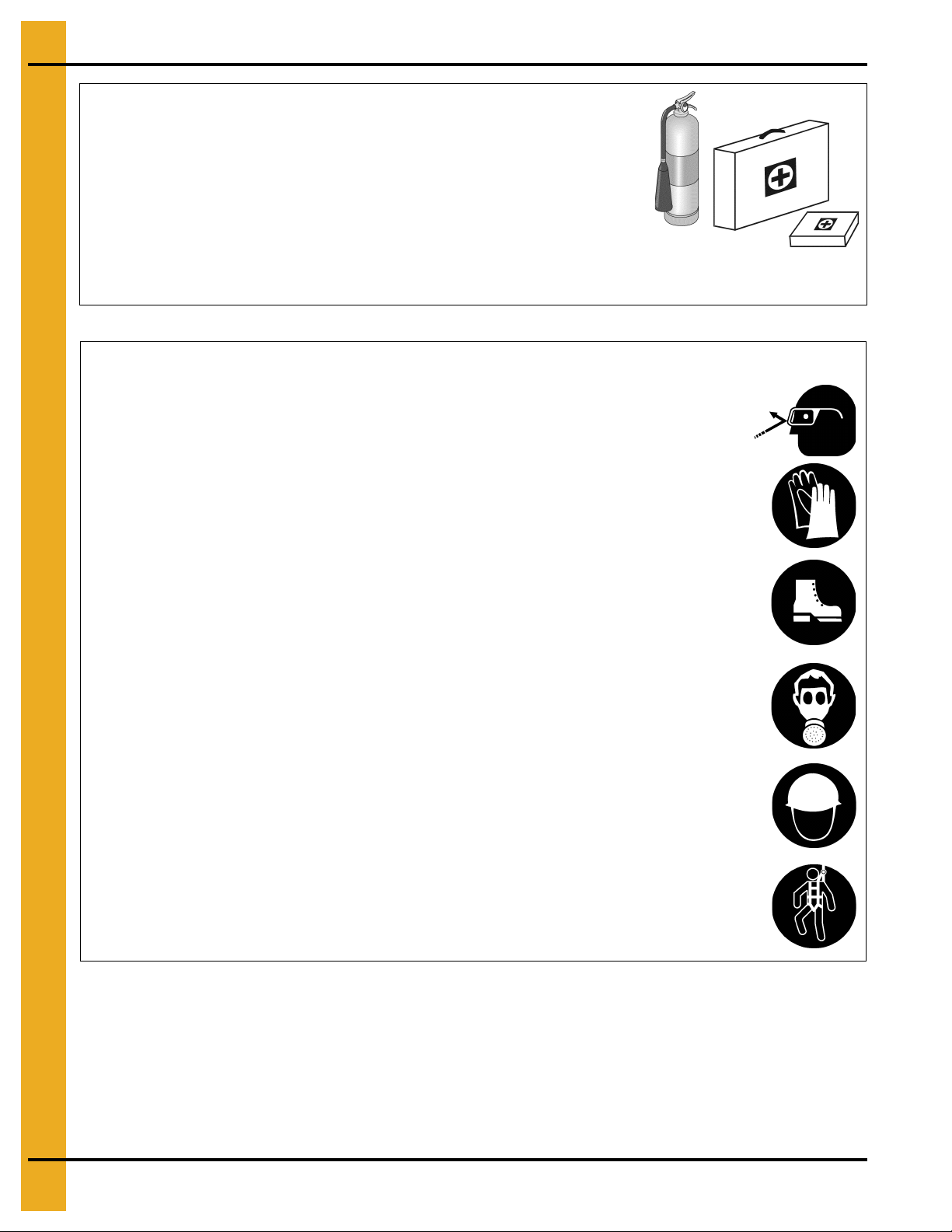
Prepare for Emergencies
Be prepared if fire starts.
Keep a first aid kit and fire extinguisher handy.
Keep emergency numbers for doctors, ambulance service,
hospital, and fire department near your telephone.
Keep Emergency Equipment
Quickly Accessible
Wear Protective Clothing
Wear close-fitting clothing and safety equipment appropriate
to the job.
Remove all jewelry.
Tie long hair up and back.
Wear safety glasses at all times to protect eyes from debris.
Wear gloves to protect your hands from sharp edges on
plastic or steel parts.
Wear steel-toed boots to help protect your feet from falling
debris. Tuck in any loose or dangling shoestrings.
A respirator may be needed to prevent breathing potentially
toxic fumes and dust.
Wear a hard hat to help protect your head.
Wear appropriate fall protection equipment when working at
elevations greater than six feet (6').
Eye Protection
Gloves
Steel-Toed Boots
Respirator
Hard Hat
Fall Protection
6 PNEG-1813 Electronic Distributor Control
Page 7
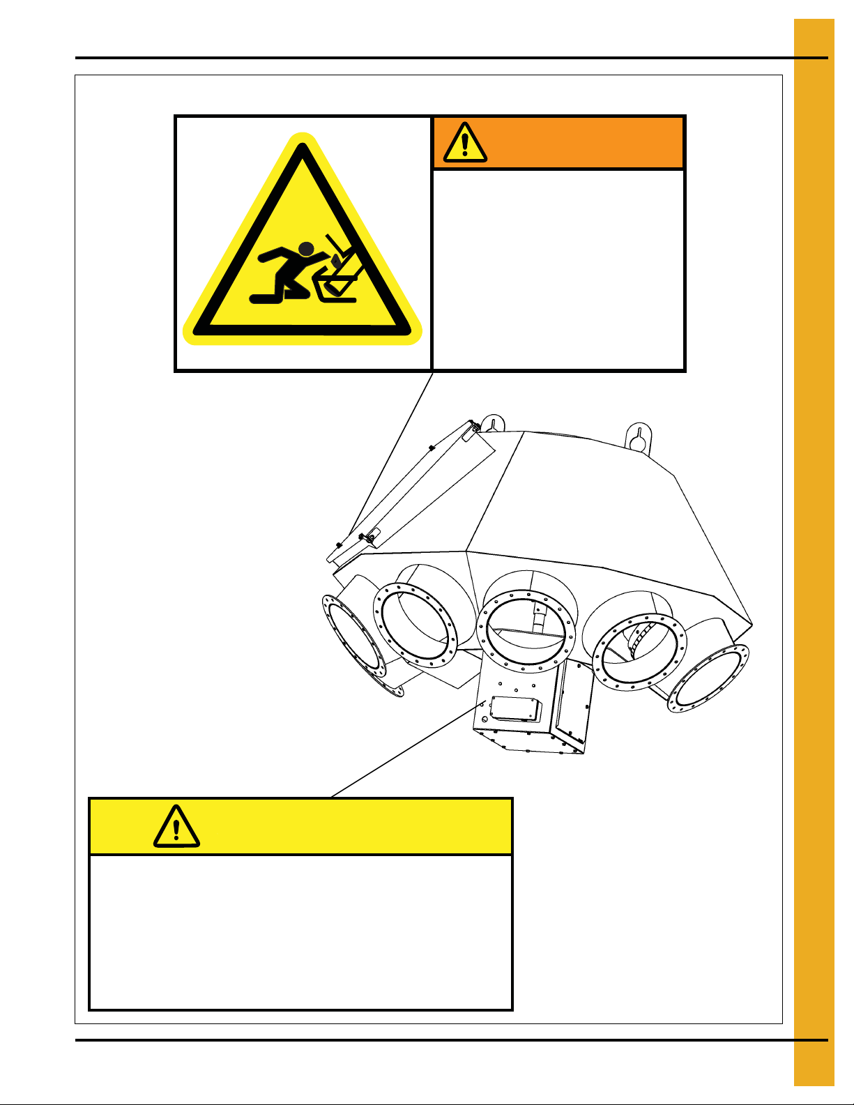
2. Decals
The decals are located as shown below:
DC-2159
WARNING
MOVING PARTS.
Rotating spout can
crush and cut.
Lock out power
before servicing.
CAUTION
Do not operate with access
panel removed.
Lock out power before servicing.
PNEG-1813 Electronic Distributor Control 7
DC-2160
Page 8
3. Installation
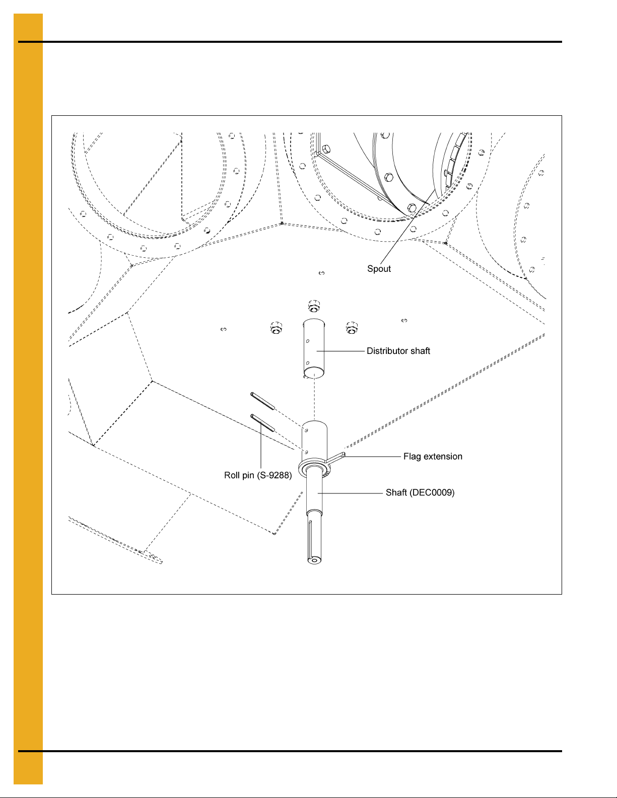
Electronic Distributor Control Shaft Installation
Install the shaft (DEC0009) to the distributor shaft using two (2) roll pins (S-9288). NOTE: Flag extension
should be installed in line with the spout to ensure proper alignment with the sensor. (See Figure 3A.)
Figure 3A Electronic Distributor Control Shaft
8 PNEG-1813 Electronic Distributor Control
Page 9
3. Installation
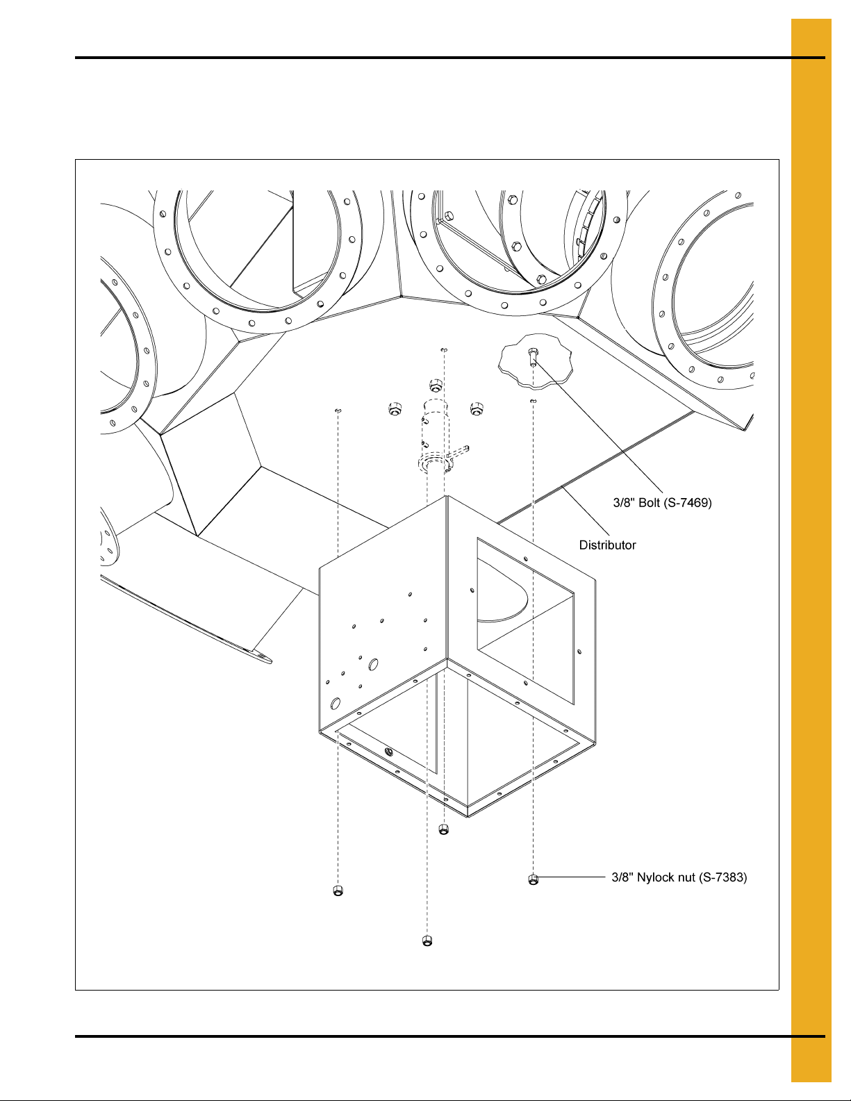
Electronic Distributor Enclosure Installation
Install the enclosure (DEC0005) to the distributor using four (4) 3/8 bolts (S-7469) and nylock nuts
(S-7383). (See Figure 3B.)
Figure 3B Electronic Distributor Enclosure
PNEG-1813 Electronic Distributor Control 9
Page 10
3. Installation
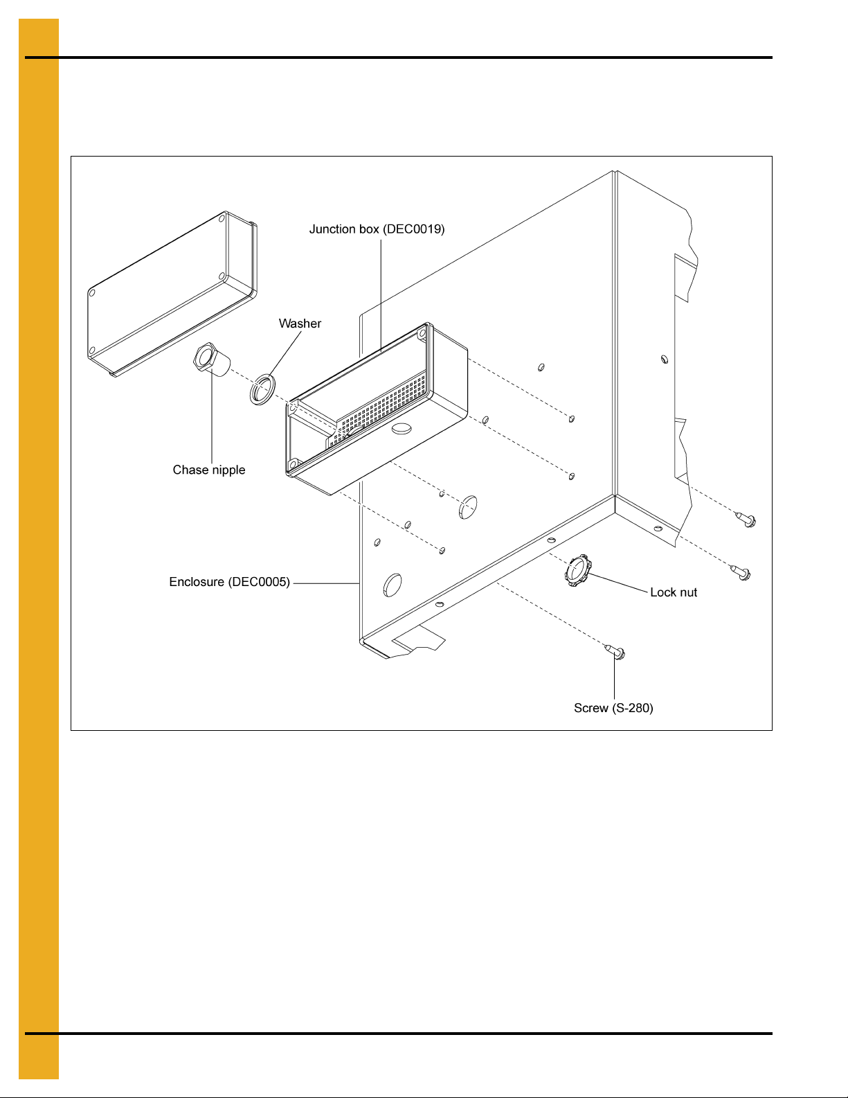
Junction Box Installation
Install the junction box (DEC0019) to the enclosure (DEC0005) using fou r (4) self-drilling screws (S-280).
Install the chase nipple, washer and lock nut. (See Figure 3C.)
Figure 3C Junction Box
10 PNEG-1813 Electronic Distributor Control
Page 11
3. Installation
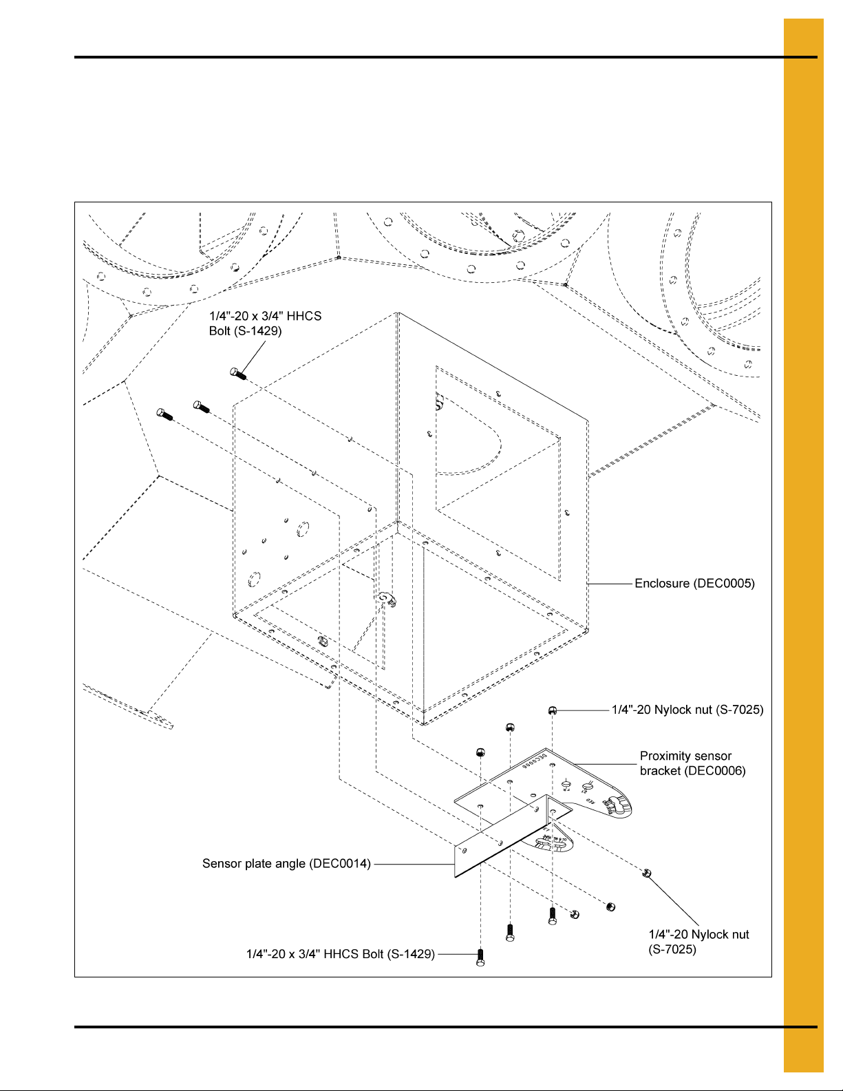
Sensor Plate Angle and Proximity Sensor Bracket Installation
Assemble the sensor plate angle (DEC0014) to the proximity sensor bracket (DEC0006) using three (3)
1/4"-20 x 3/4" HHCS bolts (S-1429) and 1/4"-20 nylock nuts (S-7025) as shown in Figure 3D.
Attach the proximity sensor bracket (DEC0006) to the inside of the enclosure (DEC0005) using three (3)
1/4"-20 x 3/4" HHCS bolts (S-1429) and 1/4"-20 nylock nuts (S-7025). (See Figure 3D.)
Figure 3D Sensor Plate Angle and Proximity Sensor Bracket
PNEG-1813 Electronic Distributor Control 11
Page 12
3. Installation
Diameter # Spouts Prox Ref #
6
4 2
65
8 6
8
65
8 7
10 9
10
6 4
810
10 9
12
41
6 3
88
10 9
14
41
6 3
8 8
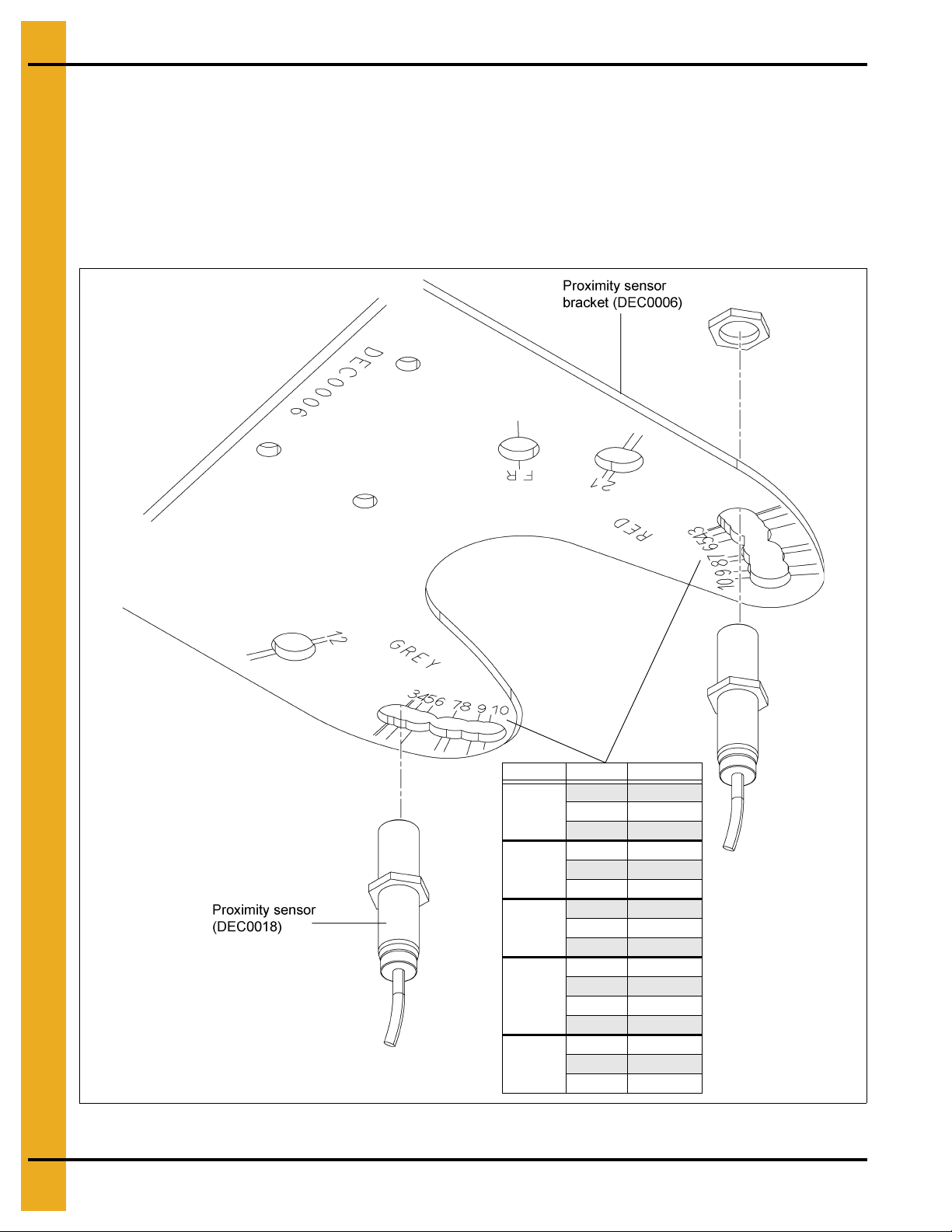
Proximity Sensor Location and Installation
NOTE: The location of the proximity sensor will be determined by the size o f the distributor. Using the table
shown in Figure 3E, locate the diameter and number of spouts of the distributor being used and note the
proximity sensor reference number. This reference number is marked on the bottom of the proximity
sensor bracket (DEC0006) and identifies the location for installing the proximity sensors (DEC0018).
Install the two (2) proximity sensors (DEC0018) into the proximity sensor bracket (DEC0006) at the
appropriate locations determined from the table. (See Figure 3E below and Figure 3G on Page 14.)
12 PNEG-1813 Electronic Distributor Control
Figure 3E Proximity Sensor Location
Page 13
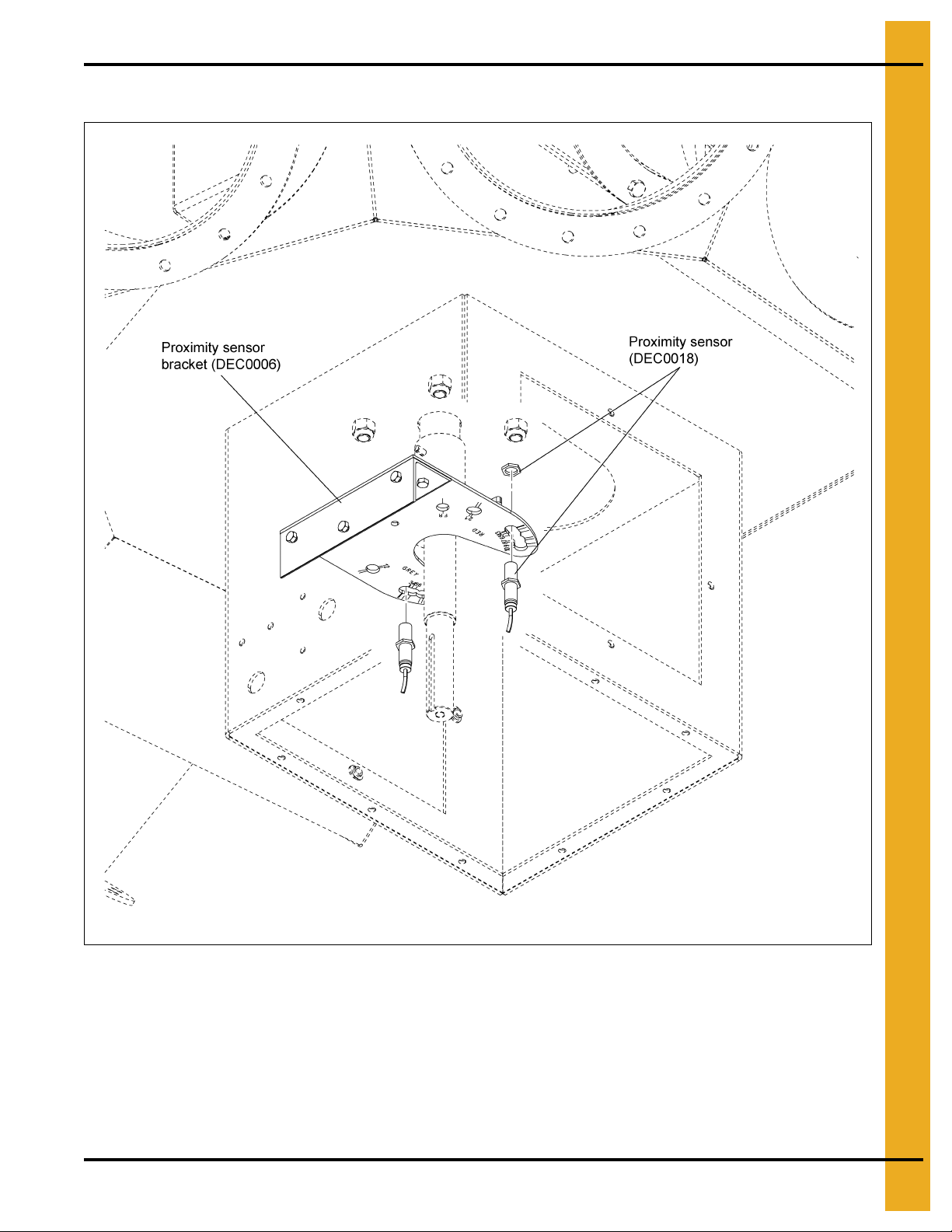
Proximity Sensor Location and Installation (Continued)
3. Installation
Figure 3F Proximity Sensor Installation
PNEG-1813 Electronic Distributor Control 13
Page 14
3. Installation
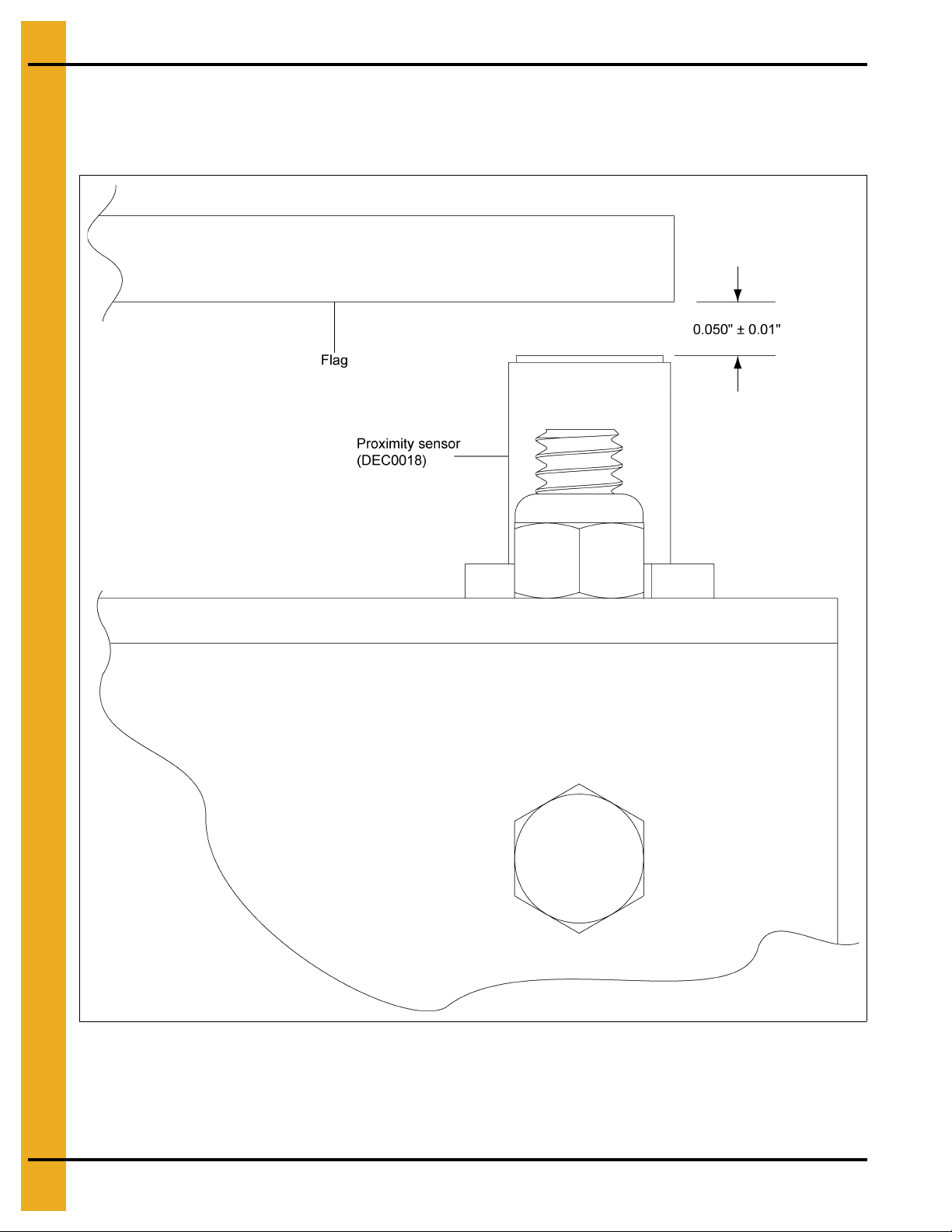
Proximity Sensor Adjustment
Set the clearance of the two (2) proximity sensors (DEC0018) to 0.050" ± 0.01" from the face of each
sensor to the flag on the shaft (DEC0009). (See Figure 3G.)
Figure 3G Proximity Sensor Adjustment
14 PNEG-1813 Electronic Distributor Control
Page 15
3. Installation
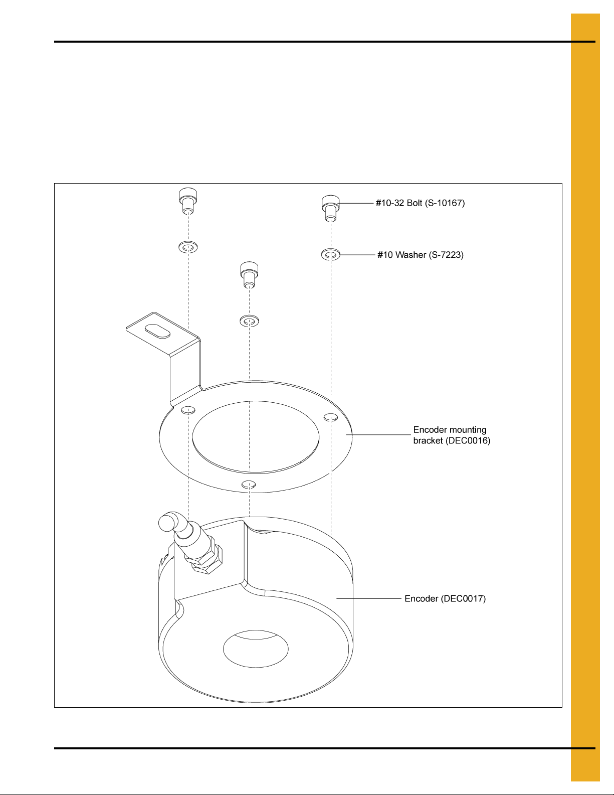
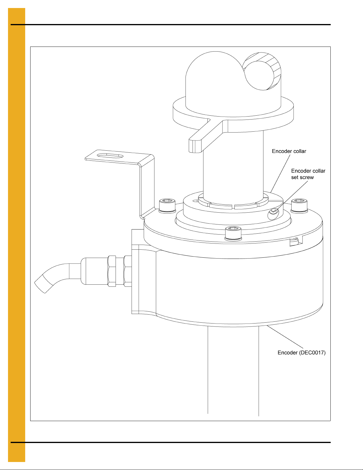
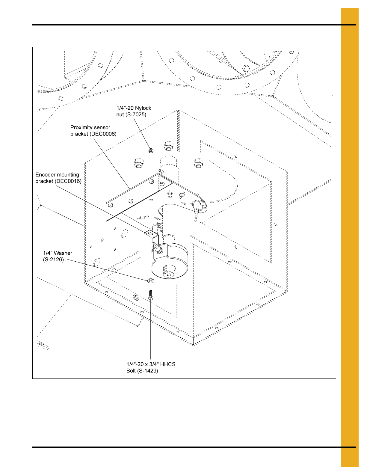
Encoder and Bracket Installation
Install the encoder (DEC0017) to the encoder mounting bracket (DEC0016) using the three (3) #10-32
bolts (S-10167) and #10 washers (S-7223) as shown in Figure 3H.
Tighten the encoder collar set screw as shown in Figure 3I on Page 16 to 8 in-lbs.
Install the encoder mounting bracket (DEC0016) to the proximity sensor bracket (DEC0006) using the
1/4"-20 x 3/4" HHCS bolt (S-1429), 1/4" washer (S-2126) and 1/4"-20 nylock nut (S-7025) as shown in
Figure 3J on Page 17.
Figure 3H Encoder to Mounting Bracket
PNEG-1813 Electronic Distributor Control 15
Page 16
3. Installation
Encoder and Bracket Installation (Continued)
Figure 3I Encoder Collar Set Screw
16 PNEG-1813 Electronic Distributor Control
Page 17
Encoder and Bracket Installation (Continued)
3. Installation
Figure 3J Mounting Bracket to Proximity Sensor Bracket
PNEG-1813 Electronic Distributor Control 17
Page 18

3. Installation
Motor Mounting Bracket Installation
Install the motor mounting bracket (DEC0003) to the enclosure (DEC0005) using two (2) 1/4"-20 x 3/4"
HHCS bolts (S-1429), 1/4" washers (S-2126) and 1/4"-20 nylock nuts (S-7025) as shown in Figure 3K.
Figure 3K Motor Mounting Bracket
18 PNEG-1813 Electronic Distributor Control
Page 19

3. Installation
Control Motor Installation
Install the motor (DEC0015) to the motor mounting bracket (DEC0003) using two (2) 1/4"-20 x 1" HHCS
bolts (S-6998), four (4) 1/4" washers (S-2126) and two (2) 1/4"-20 nylock nuts (S-7025) as shown
in Figure 3L.
Install second motor mounting bracket (DEC0021) to the enclosure (DEC0005) using two (2) 1/4"-20 x
3/4" HHCS bolts (S-1429), 1/4" washers (S-2126) and 1/4"-20 nylock nuts (S-7025). Then install the motor
to the motor mounting bracket (DEC0021) using two (2) 1/4"-20 x 1" HHCS bolts (S-6998), four (4)
1/4" washers (S-2126) and two (2) 1/4"-20 nylock nuts (S-7025) as shown in Figure 3L.
Figure 3L Control Motor Installation
PNEG-1813 Electronic Distributor Control 19
Page 20

3. Installation
Wire and Fitting Selection Recommendations
NOTE: The power cable, encoder cable, proximity sensor cables, motor cable and electrical fittings are
not supplied with the electronic distributor control. The following recommendations must be followed
when selecting wire types and electrical fittings:
For the proximity sensor and encoder cables from the junction box to the control panel, use ten (10)
conductor or greater shielded cable, 22 AWG or larger and rated for the environment. If the wiring is run
outside of conduit, it should be rated for UV.
For the motor cable from the motor to the control panel, use four (4) conductor cable, shielded, 16 AWG
or larger and rated for the environment. If the wiring is run outside of conduit, it should be rated for UV.
All conduit and fittings should be outdoor-rated to keep things adequately sealed.
20 PNEG-1813 Electronic Distributor Control
Page 21

3. Installation
Distributor to Junction Box Electrical Connections
Connect wiring from proximity sensors (DEC0018) and encoder (DEC0017) to junction box terminal block
as shown in Figure 3M. NOTE: The grey and red color identifiers indicate the location of the proximity
sensors and are shown on the bottom of the proximity sensor bracket (DEC0006).
Junction box
(DEC0019)
Proximity sensor
bracket (DEC0006)
Junction box
terminal block
Encoder (DEC0017)
Proximity sensor
(DEC0018)
Junction box
terminal block
1
2
Encoder
Prox Red
Prox Grey
RED
BLUE
PINK
WHITE
BROWN
BLUE
BLACK
BROWN
BLUE
BLACK
34123123
Blue
section
Red
section
Grey
section
Figure 3M Distributor to Junction Box Electrical Co nnections
PNEG-1813 Electronic Distributor Control 21
Page 22

3. Installation
Enclosure (DEC0005)
Motor cable
Proximity sensors
and encoder cable
Junction box
(DEC0019)
Control Panel Cable to Distributor Fitting Connections
Connect the motor cable from the control panel to the distributor enclosure (DEC0005) and connect the
proximity sensors and encoder cable from the control panel to the junction box (DEC0019) using suitable
fittings. (See Figure 3N.)
Figure 3N Cable fitting connections to distributor enclosure and junction box.
22 PNEG-1813 Electronic Distributor Control
Page 23

3. Installation
Motor junction
box cover
Motor junction
box
Motor junction
box cover
screw
Motor cable
Motor Cable to Motor Junction Box Fitting Connections
Remove the four (4) motor junction box cover screws and the motor junction box cover as shown
in Figure 3O.
Connect the motor cable to the motor junction box using suitable fittings. (See Figure 3O.)
Figure 3O Cable fitting connection to motor junction box.
PNEG-1813 Electronic Distributor Control 23
Page 24

3. Installation
Electronic Distributor Wiring Diagram
The electric motor supplied with the GSI Electronic Distributor Control system is designed to be capable
of running on either low or high voltage. The variable frequency drive (VFD) supplied with the system
supplies 230V 3 phase power and requires that the electric motor be configured for low voltage operation.
In order to ensure proper operation, ensure the motor jumpers are configured in accordance with the
wiring diagram shown for low voltage operation. (See Figure 3P.)
Figure 3P
24 PNEG-1813 Electronic Distributor Control
Page 25

3. Installation
Motor wiring
terminal block
Wire W
Wire V
Wire U
Ground wire
Motor cable
Motor Wiring to Motor Junction Box Electrical Connections
Connect the motor wiring to the motor wiring terminal block as shown in Figure 3Q and re-install the motor
junction box cover and screws.
Figure 3Q Motor Wiring to Motor Junction Box Elec tric al Co nn ections
PNEG-1813 Electronic Distributor Control 25
Page 26

3. Installation
Control Panel Wiring to Junction Box Electrical Connections
Connect the wiring from the control panel to the junction box (DEC0019) terminal block as shown in
Figure 3R. NOTE: The grey and red color identifiers indicate the location of the proximity sensors and are
marked on the bottom of the proximity sensor bracket (DEC0006).
Junction box
terminal block
Junction box
(DEC0019)
Junction box
terminal block
Blue
section
Red
section
2134123123
NOTE: Wire colors
for reference only.
ORANGE
BLUE
BROWN
WHITE
RED
GREEN
BLACK
Prox Red
Encoder
Grey
section
YELLOW
RED
BLACK
Prox Grey
Figure 3R Control Panel Wiring to Junction Box Electrical Connections
26 PNEG-1813 Electronic Distributor Control
Page 27

3. Installation
Enclosure Covers Installation
Install the two (2) side access covers (DEC0012) using four (4) 1/4"-20 x 3/4" HHCS bolts (S-1429)
and 1/4" lock washer (S-2041) each and install the bottom enclosure cover (DEC0013) using ten (10)
1/4"-20 x 3/4" HHCS bolts (S-1429) and 1/4" lock washers (S-2041) as shown in Figure 3S.
Figure 3S Enclosure Covers Installation
PNEG-1813 Electronic Distributor Control 27
Page 28

3. Installation
Ground terminal block
Wire U
Wire W
Wire V
Ground wire
Control Panel Wiring from Motor Electrical Connections
Connect the motor wiring to the motor power terminal block in the control panel as shown in Figure 3T.
Figure 3T Control Panel Wiring from Motor Electrical Connections
28 PNEG-1813 Electronic Distributor Control
Page 29

3. Installation
Control panel
circuit breakers
Hot wires
Power cable
hardware
Power supply
ground wire
Power Supply Wiring to Control Panel Electrical Connections
NOTE: Ensure the power supply voltage source is OFF before installation.
Install power supply cable through the control panel using suitable hardware as shown in Figure 3U.
Connect the power supply hot wires to the control panel circuit breakers as shown in Figure 3U.
Connect the power supply ground wire as shown in Figure 3U to the ground terminal block as shown
in Figure 3T on Page 28.
Figure 3U Control Panel Wiring from Motor Electrical Connections
PNEG-1813 Electronic Distributor Control 29
Page 30

3. Installation
Control Panel Installation Guidelines
The following recommendations must be followed when installing and mounting the control panel:
All wiring should be performed by a licensed/qualified electrician in accordance with the National Electric
Code (NEC), state codes and local codes.
Never mount the control panel immediately beside or above heat generating equipment or directly below
water or steam pipes.
The atmosphere surrounding the control panel must be free of combustible vapors, chemical fumes and
corrosive materials.
The location of the control panel and the routing of cables should provide safe access for maintenance
and suitable operation of the control panel.
Mount the control panel on a flat, vertical surface using 1/4" fasteners.
Ensure that the mounting surface is sufficient to support the weight of the control panel.
30 PNEG-1813 Electronic Distributor Control
Page 31

4. Operation Procedures
Initializing Screen
When powering up the distributor the first screen that appears is the “Initializing” screen. (See Figure 4A.)
Press “OK” to proceed to the “Main” screen. See “Main Screen” on Page 32.
NOTE: Pressing “OK” button after first time power up after a retrofit will bring you to the
configuration screen.
Figure 4A Help Menu
NOTE: The following screens are taken from various models of distributors, which may result in
differences between this manual and that of the actual display.
PNEG-1813 Electronic Distributor Control 31
Page 32

4. Operation Procedures
CURRENT SPOUT SELECTION:
BIN 1
CURRENT SPOUT SELECTION:
BIN 1
CURRENT SPOUT SELECTION:
BIN 1
CURRENT SPOUT SELECTION:
BIN 1
Main Screen
Depending on the number of spouts in the current configuration, one of the following screens will be
displayed. (See Figure 4B, Figure 4C, Figure 4D and Figure 4E.) The name of the current spout is
indicated at the top of the screen and is indicated in the graphic with a green circle. At the bottom of the
screen are three (3) buttons to navigate to either the Help Menu, Move Screen or Setup Menu.
Figure 4B Four (4) Spout Main Screen
Figure 4C Six (6) Spout Main Screen
Figure 4D Eight (8) Spout Main Screen
Figure 4E Ten (10) Spout Main Screen
32 PNEG-1813 Electronic Distributor Control
Page 33

4. Operation Procedures
Help Menu Screen
The help menu has three (3) options for displaying troubleshooting information for different faults that may
appear during the operation of the distributor. (See Figure 4F.)
Figure 4F Help Menu Screen
Movement Fault: Displays the “Movement Fault” screen which offers possible causes and solutions to
faults caused by distributor movement. (See Figure 4G on Page 34.)
Home Prox Fault: Displays the “Home Sensor Fault” screen which offers possible causes and solutions
to faults caused by a proximity switch failure. (See Figure 4H on Page 34.)
Drive Fault: Displays the “VFD” Fault screen which offers possible causes and solutions to faults caused
by the variable frequency drive. (See Figure 4I on Page 35.)
PNEG-1813 Electronic Distributor Control 33
Page 34

4. Operation Procedures
Movement Fault Screen
Home Prox Fault Screen
Figure 4G Movement Fault Screen
Figure 4H Home Prox Fault Screen
34 PNEG-1813 Electronic Distributor Control
Page 35

Drive Fault Screen
4. Operation Procedures
Figure 4I Drive Fault Screen
Move Screen
This screen allows the user to change the distributor’s current spout position. The green highlighted spout
number indicates the current selection. A spout number with a red circle with a line through it indicates a
position that is currently locked out. (See “Position Lock-Out Screen” on Page 42.) (See Figure 4J.)
NOTE: The default names for each spout will be “BIN #”, see “Position Names Screen” on Page 38 for
customizing the spout names.
Figure 4J Move Screen
PNEG-1813 Electronic Distributor Control 35
Page 36

4. Operation Procedures
Moving Spout Position
1. From the “Main” screen or the “Setup Menu” select “MOVE” to view the “Move Position” screen.
(See Figure 4J on Page 35.)
2. On the “Move Position” screen, select the position you want the spout to move to by pressing the
spout name on the screen.
3. The “Main Menu” screen will now display a flashing message “Moving to” at the top of the screen,
the selected spout number will flash yellow while the pointer is moving to the selected spout. The
destination spout number will turn green when the move is complete.
Verifying Spout Alignment
NOTE: In the following steps, the distributor must be in a position to view the spout location in the
distributor to verify that it lines up correctly. If the distributor is installed above ground level,
two (2) people will be needed; one to verify the alignment of the distributor spout and one to
operate the controller.
1. From the “Main” screen or the “Setup Menu” select “MOVE” to view the “Move Position” screen.
(See Figure 4J on Page 35.)
2. On the “Move Position” screen, select the position you want the spout to move to by pressing the
spout name on the screen.
3. The “Main Menu” screen will now display a flashing message “Moving to” at the top of the screen,
the selected spout number will flash yellow while the pointer is moving to the selected spout. The
destination spout number will turn green when the move is complete.
4. Once the spout has finished moving, visually check and verify the spout is centered with the
distributor discharge spout. If alignment requires adjustment, see “Position Locations Screen”
on Page 40 to adjust the positioning.
5. Repeat procedure for any other spouts that were re-positioned.
Setup Menu Screen
Figure 4K Setup Menu Screen
36 PNEG-1813 Electronic Distributor Control
Page 37

4. Operation Procedures
Configuration Setup: Displays the machine setup screen that allows the user to change the distributor’s
parameters or reload default values. See “Configuration Setup Screen” on Page 37.
Position Names: Allows the user to assign or change the name of each spout position and to create or
change a name for the distributor. See “Position Names Screen” on Page 38.
Position Locations: Displays the positioning screen which allows the user to set the value that aligns the
spouts with the distributor. See “Position Locations Screen” on Page 40.
Position Lock-Out: Allows the user to lock or unlock spouts from being used. See “Position Lock-Out
Screen” on Page 42.
Homing Interval: Allows the user to set the number of times before the “Perform Homing Now” warning
appears. See “Homing Interval Screen” on Page 43.
Perform Homing Now: Press this to perform the homing operation to re-calibrate the distributor.
Configuration Setup Screen
This screen allows the user to change the distributor’s spout diameter property, total of number of spouts
and for resetting the distributor back to the default settings. (See Figure 4L.)
Figure 4L Configuration Setup Screen
Diameter of Spouts: Press the button that matches the size of the spout that is currently installed on the
distributor. The diameter that is selected will turn green and the number of spouts available for that
diameter will be displayed.
Number of Spouts: Press the button that matches the current configuration of the distributor. The number
that is selected will turn green. The number of spout options will change according to the diameter of spout
selected.
Reload Defaults: If during operation, any configuration parameters are altered from the original settings,
pressing this button will revert settings to the default values.
OK: Press this button to save the current configuration and be brought back to the Setup Menu.
PNEG-1813 Electronic Distributor Control 37
Page 38

4. Operation Procedures
NOTE: A warning message will appear if distributor has already been previously configured.
(See Figure 4M.)
Figure 4M
Position Names Screen
This screen allows the user to individually name each of the distributor discharge spouts and is also used
to create or modify a distributor name. (See Figure 4N.)
Figure 4N Create/Modify Spout Names
38 PNEG-1813 Electronic Distributor Control
Page 39

4. Operation Procedures
Create/Modify Spout Name
1. From the “Setup Menu”, select “Position Names” to bring up the “Create/Modify Spout
Names” screen.
2. Press the spout name to be modified to display an alphanumeric keypad. (See Figure 4O.)
Figure 4O Alphanumeric Keypad
3. Type in the desired name for the spout position and press “enter”.
4. Select “OK” to return to “Setup Menu”.
Create/Modify Distributor Name
1. From the “Setup Menu”, select “Position Names” to bring up the “Create/Modify Spout
Names” screen.
2. Next to ochre “Distributor Name” label, press the distributor name to display an alphanumeric keypad.
(See Figure 4O.)
3. Type in the desired name for the spout position and press “enter”.
4. Select “OK” to return to “Setup Menu”.
PNEG-1813 Electronic Distributor Control 39
Page 40

4. Operation Procedures
Position Locations Screen
This screen allows the user to adjust the spout positioning so it lines up with the center of the distributor
discharge. Adjustments can be made individually or an offset can be used to adjust all spouts by the same
amount. (See Figure 4P.)
Figure 4P Modify Spout Positioning
Modify Spout Positioning
1. From the “Setup Menu”, select “Position Locations” to bring up the “Modify Spout Positioning” screen.
2. In the “Modify Spout Positioning” screen select the spout that requires adjustment by touching the
value pad next to the spout number balloon. A number keypad will display. (See Figure 4Q.)
Figure 4Q Number Keypad
40 PNEG-1813 Electronic Distributor Control
Page 41

4. Operation Procedures
3. Insert the desired value and press “enter”.
NOTE: Entering a value larger than the existing value will move spout position to the left, entering a
smaller value will move the position to the right.
4. Select “OK” to return to “Setup Menu”.
5. Verify spout alignment with distributor. See “Verifying Spout Alignment” on Page 36.
Offset All
1. From the “Setup Menu”, select “Position Locations” to bring up the “Modify Spout Positioning” screen.
2. In “Modify Spout Positioning” screen select the “0” key pad next to “OFFSET ALL”. A number keypad
will display. (See Figure 4R.)
Figure 4R Help Menu Screen
3. Insert the desired value and press “enter”.
To offset the spouts to the left, use a positive value and to offset to the right, use a negative value.
NOTE: A maximum offset at any one time is ± 5.
4. Select “OK” to return to “Setup Menu”.
5. Verify each spout alignment with distributor. See “Verifying Spout Alignment” on Page 36.
PNEG-1813 Electronic Distributor Control 41
Page 42

4. Operation Procedures
Position Lock-Out Screen
The position lock-out allows you to lock-out a distributor discharge spout position so it can not be used
until it is manually unlocked. (See Figure 4S.)
Figure 4S Lock/Unlock Position
Lock/Unlock Position
1. From the “Setup Menu”, select “Position Lock-Out” to display the “Lock/Unlock Position”
setup screen.
2. Press name of spout to toggle between locked and unlocked. When in the lo cked position the number
balloon will change to a red circle with a line through it.
NOTE: The position that the distributor is currently located, indicated by a green number balloon
icon, can not be locked out. Move the spout position to a different location then try again.
See “Move Screen” on Page 35.
3. Select “OK” to apply changes and return to “Main Menu”.
42 PNEG-1813 Electronic Distributor Control
Page 43

4. Operation Procedures
Homing Interval Screen
The homing interval screen allows the user to set the number of times the distributor position may be
moved before a warning displays for home position re-calibration. The lower value of this number, the
greater the positioning accuracy. A default value of 50 is standard. (See Figure 4T.)
Figure 4T Homing Interval Screen
Setting Homing Interval
1. To access the homing interval from the “Setup Menu”, select “Homing Interval” to display the “Homing
Interval” setup screen.
2. Press the button under the “Homing Interval” label. A number keypad will display. (See Figure 4U.)
Figure 4U
3. Insert the desired value and press “enter”.
4. Select “OK” to apply changes and return to “Main Menu”.
PNEG-1813 Electronic Distributor Control 43
Page 44

4. Operation Procedures
Homing Warning
To help ensure accurate positioning of the distributor a homing warning will display when the number of
times the distributor is repositioned is equal to the homing interval. This message will occur every time that
a spout move is attempted until the homing procedure is completed. The user will be given two (2) options:
“Home Now” and “Home Next Move”. (See Figure 4V.)
Figure 4V Homing Warning
Home Now
Select to perform the homing calibration immediately. The user interface will return to the “MAIN”
screen and “Homing” will flash ON and OFF in yellow. After homing is complete, the spout will return to
the selected position.
Home Next Move
Select “Home Next Move” to skip the homing operation and move to the selected position. The user
interface will continue to prompt you to home the unit during every subsequent move until homing
is performed.
44 PNEG-1813 Electronic Distributor Control
Page 45

4. Operation Procedures
Manual/Jog dial
Manual Override
Located on the front of the controller is a manual/jog dial. This manual override is key locked and should
only be used in case of a major equipment failure. It allows for manually moving the spout in the direction
you turn the dial when the key is inserted.
It is recommended that two (2) people perform this procedure. One person to operate the manual/jog dial
and another to look through the distributor and verify alignment of the spout. (See Figure 4W.)
NOTE: Panel will not close with key inserted in the manual/jog dial. Always keep key in a safe location for
access by authorized personnel only.
PNEG-1813 Electronic Distributor Control 45
Figure 4W
Page 46

5. Parts List
Assembly Procedure:
1. Install shaft (DEC0009) with provided roll
pins (S-9288).
2. Install enclosure (DEC0005) with 3/8" bolts and
nylock nuts.
3. Install junction box (DEC0019) with self-drilling
screws (S-280).
4. Install sensor mounting angle (DEC0014) and plate
(DEC0006).
5. Install sensors (DEC0018, 2 EA) and set clearance.
(See detail A.)
6. Install encoder (DEC0017), torque set screw to
8 in-lbs.
7. Install motor (DEC0015) and mount brackets
(DEC0003 and DEC0021).
8. Install bottom (DEC0021) and side (DEC0013)
covers.
NOTE: Install sensors in #3 hole on both sides.
Set 0.050" ± 0.01" clearance from face of each
sensor to flag on shaft.
12" 6 Hole 45° Distributor Assembly Electronic Control
(DFB12645G-EC)
46 PNEG-1813 Electronic Distributor Control
Page 47

5. Parts List
12" 6 Hole 45° Distributor Assembly Electronic Control (DFB12645G-EC) Parts List
Ref # Part # Description Qty
1 DFB12645G 12" 6 Hole 45° Distributor Assembly 1
2 DEC0009 Weldment, Shaft and Flag, 1/2 HP Distributor Control 1
3 DEC0005 Weldment, Enclosure, 1/2 HP Distributor Control 1
4 DEC0014 Angle, Sensor Plate Mounting, 1/2 HP Distributor Control 1
5 DEC0006 Bracket, Proximity Sensor, 1/2 HP Distributor Control 1
6 DEC0015 Gear Motor, DBL WRM, 1/2 HP, 400:1, Distributor Control 1
7 DEC0003 Bracket, Motor Mount, 1/2 HP Distributor Control 1
8 DEC0016 Bracket, Encoder Mount, Distributor Control 1
9 DEC0017 Encoder, INCR, 2048 PPR, 30 mm, Distributor Control 1
10 DEC0018 Sensor, Proximity, Inductive, 12 mm, S=4 2
11 DEC0019 Box, Junction, 1/2 HP Distributor Control 1
12 DEC0013 Cover, Side Access, 1/2 HP Distributor Control 2
13 DEC0012 Cover, Enclosure Bottom, 1/2 HP Distributor Control 1
14 S-2041 Split Lock Washer 1/4" ZN 18
15 S-1429 Bolt, HHCS 1/4"-20 x 3/4" ZN Grade 2 29
16 S-2126 Flat Washer 1/4" x 2-5/8" SAE ZN Grade 2 11
17 S-6998 Bolt, HHCS 1/4"-20 x 1" ZN Grade 5 4
18 S-7025 Nylock Nut 1/4"-20 ZN Grade 5 15
19 S-9288 Spring Pin 1/4" x 2-1/2" Plain Steel Slotted Rolled 2
20 S-7469 Bolt, HHCS 3/8"-16 x 1" ZN Grade 5 5
21 S-7383 Nylock Nut 3/8"-16 ZN Grade 5 4
22 S-10200 Fender Washer 3/8" x 1-1/2" O.D. ZN 1
23 S-280 Screw, SDS #10-16 x 5/8" HWH ZN 4
24 S-7223 Split Lock Washer #10 ZN 3
25 S-10167 Bolt, SHCS #10-32 x 1/4" ZN 3
26 DEC0021 Bracket, Motor Mount Short, 1/2 HP Distributor Control 1
27 DC-2160 Decal, Caution, Do not Operate with Access Panel 1
28 DC-2159 Decal, Warning, Rotating Spout can Crush and Cut 1
PNEG-1813 Electronic Distributor Control 47
Page 48

6. Troubleshooting
Any changes to the settings will alter factory defaults and may result in da mage
to equipment. To exit without changes, select CLOSE and then OK.
Error Messages
Message
The value entered was greater than the allowable deviation from the original position. Please e nter
a value between “X” and “Z”.
Reason
This error is displayed when a position count value outside the acceptable range is entered while in the
“Modify Spout Position” screen.
Remedy
Enter a value between “X” and “Z” on the “Modify Spout Position” screen.
Message
WARNING
Reason
This message is displayed as you enter the “Configuration Setup” screen.
Message
The home proximity sensor was not detected. The homing process failed. Please check for proper
operation of the sensor.
Reason
This error is displayed when attempting to perform a “Homing” operation and the controller fails to receive
a proximity sensor signal before the time out period is reached.
Remedy
Check wiring, wiring connections and proximity sensors. Repair or replace as necessary.
Message
The position feedback does not match expected behavior. Please check for proper operation of
the encoder.
Reason
This error is displayed if the spout does not reach the desired position count while performing a
“MOVE” operation.
Remedy
Check wiring, wiring connections and encoder. Repair or replace as necessary.
48 PNEG-1813 Electronic Distributor Control
Page 49

6. Troubleshooting
Message
The VFD has faulted. Please check for proper operation of the VFD.
Reason
This error displays when the variable frequency drive does not perform properly.
Remedy
Repair or replace the VFD as necessary.
Message
The bucket elevator is running. Please stop feed before moving.
Reason
This error displays when trying to perform a move while bucket elevator is running.
Remedy
Stop bucket elevator before performing spout move.
Message
You cannot lock-out this position because it is currently in use. Move the spout to a different
position and then lock-out this position.
Reason
This error displays when trying to lock-out a spout position that is in use.
Remedy
Move spout to a different position and then lock-out this position.
Message
You are attempting to move to the currently selected position. Please select a different position.
Reason
This error displays when trying to move spout to current position.
Remedy
Select a different position.
PNEG-1813 Electronic Distributor Control 49
Page 50

6. Troubleshooting
Message
You cannot select a locked-out position. Please select a different position.
Reason
This error displays when trying to choose a spout position that is locked out.
Remedy
Select a different position.
Message
The spout has drifted out of position. Please verify current position of the spout.
Reason
This error occurs when spout position reading changes without a move command being issued.
Remedy
Check mechanical components for looseness, wear or damage. Repair or replace as necessary.
50 PNEG-1813 Electronic Distributor Control
Page 51

White Panel Layout
7. Schematic and Wiring Diagrams
Figure 7A
PNEG-1813 Electronic Distributor Control 51
Page 52

7. Schematic and Wiring Diagrams
White Panel Electrical Schematic
Figure 7B
52 PNEG-1813 Electronic Distributor Control
Page 53

7. Schematic and Wiring Diagrams
White Panel Electrical Schematic (Continued)
Figure 7C
PNEG-1813 Electronic Distributor Control 53
Page 54

NOTES
54 PNEG-1813 Electronic Distributor Control
Page 55

8. Warranty
9101239_1_CR_rev7.DOC (revised July 2009)
GSI Group, LLC Limited Warranty
The GSI Group, LLC (“GSI”) warrants products which it manufactures to be free of defects in materials and workmanship
under normal usage and conditions for a period of 12 months after sale to the original end-user or if a foreign sale,
14 months from arrival at port of discharge, whichever is earlier. The end-user’s sole remedy (and GSI’s only obligation)
is to repair or replace, at GSI’s option and expense, products that in GSI’s judgment, contain a material defect in materials
or workmanship. Expenses incurred by or on behalf of the end-user without prior written authorization from the GSI
Warranty Group shall be the sole responsibility of the end-user.
Warranty Extensions:
The Limited Warranty period is extended for the following products:
Product Warranty Period
Performer Series Direct Drive Fan Motor 3 Years
AP Fans and Flooring
Cumberland
Feeding/Watering
Systems
Grain Systems Grain Bin Structural Design 5 Years
Grain Systems
Farm Fans
Zimmerman
All Fiberglass Housings Lifetime
All Fiberglass Propellers Lifetime
Feeder System Pan Assemblies 5 Years **
Feed Tubes (1-3/4" and 2.00") 10 Years *
Centerless Augers 10 Years *
Watering Nipples 10 Years *
Portable and Tower Dryers 2 Years
Portable and Tower Dryer Frames and
Internal Infrastructure †
5 Years
* Warranty prorated from list price:
0 to 3 years - no cost to end-user
3 to 5 years - end-user pays 25%
5 to 7 years - end-user pays 50%
7 to 10 years - end-user pays 75%
** Warranty prorated from list price:
0 to 3 years - no cost to end-user
3 to 5 years - end-user pays 50%
† Motors, burner components
and moving parts not included.
Portable dryer screens included.
Tower dryer screens not included.
GSI further warrants that the portable and tower dryer frame and basket, excluding all auger and auger drive components,
shall be free from defects in materials for a period of time beginning on the twelfth (12
and continuing until the sixtieth (60
th
) month from the date of purchase (extended warranty period). During the extended
th
) month from the date of purchase
warranty period, GSI will replace the frame or basket components that prove to be defective under normal conditions
of use without charge, excluding the labor, transportation, and/or shipping costs incurred in the performance of this
extended warranty.
Conditions and Limitations:
THERE ARE NO WARRANTIES THAT EXTEND BEYOND THE LIMITED WARRANTY DESCRIPTION SET FORTH
ABOVE. SPECIFICALLY, GSI MAKES NO FURTHER WARRANTY OF ANY KIND, EXPRESS OR IMPLIED,
INCLUDING, WITHOUT LIMITATION, WARRANTIES OF MERCHANTABILITY OR FITNESS FOR A PARTICULAR
PURPOSE OR USE IN CONNECTION WITH: (I) PRODUCT MANUFACTURED OR SOLD BY GSI OR (II) ANY ADVICE,
INSTRUCTION, RECOMMENDATION OR SUGGESTION PROVIDED BY AN AGENT, REPRESENTA TIVE OR
EMPLOYEE OF GSI REGARDING OR RELATED TO THE CONFIGURATION, INSTALLATION, LAYOUT, SUITABILITY
FOR A PARTICULAR PURPOSE, OR DESIGN OF SUCH PRODUCTS.
GSI shall not be liable for any direct, indirect, incidental or consequential damages, including, without limitation, loss of
anticipated profits or benefits. The sole and exclusive remedy is set forth in the Limited Warranty, which shall not exceed
the amount paid for the product purchased. This warranty is not transferable and applies only to the original end-user. GSI
shall have no obligation or responsibility for any representations or warranties made by or on behalf of any dealer, agent
or distributor.
GSI assumes no responsibility for claims resulting from construction defects or unauthorized modifications to products
which it manufactured. Modifications to products not specifically delineated in the manual accompanying the equipment at
initial sale will void the Limited Warranty.
This Limited Warranty shall not extend to products or parts which have been damaged by negligent use, misuse, alteration,
accident or which have been improperly/inadequately maintained. This Limited Warranty extends solely to products
manufactured by GSI.
Prior to installation, the end-user has the responsibility to comply with federal, state and local codes which apply to the
location and installation of products manufactured or sold by GSI.
PNEG-1813 Electronic Distributor Control 55
Page 56

This equipment shall be installed in accordance with
the current installation codes and applicable
regulations, which should be carefully followed in all
cases. Authorities having jurisdiction should be
consulted before installations are made.
Copyright © 2012 by GSI Group
Printed in the USA
GSI Group
1004 E. Illinois St.
Assumption, IL 62510-0020
Phone: 1-217-226-4421
Fax: 1-217-226-4420
www.gsiag.com
CN-209332
 Loading...