

Page 1
PNEG-1798
Tower and T-Series
Dryers Vaporizer
Installation Manual
PNEG-1798
Version: 1.0
Date: 11-11-11
Page 2

2 PNEG-1798 Tower and T-Series Dryers Vaporizer
Page 3

Table of Contents
Contents
Chapter 1 Safety .....................................................................................................................................................4
Safety Guidelines .................................................................................................................................. 4
Safety Instructions ..................... ... .... ...................................... .... ... ... ... ... .... ........................................... 5
Chapter 2 Decals ....................................................................................................................................................7
Chapter 3 Purpose .................................................................................................................................................9
Chapter 4 Precautions and Limitations .............................................................................................................10
Chapter 5 References ..........................................................................................................................................11
Chapter 6 Measuring and Special Equipment Required ..................................................................................12
Chapter 7 Procedure ............................................................................................................................................13
Dryer Data Information (from its GSI Data Plate) ................................................................................ 13
Vaporizer Hardware Verification ......................................................................................................... 13
Vaporizer Coil and Piping Installation ................................................................................................. 18
Vaporizer High Pressure Leak Testing ............................................................................................... 25
Chapter 8 TD-VIP-01 Data Sheet Selection .................... ....................................................... .............................29
TD-VIP-01 Data Sheet ........................................................................................................................ 29
Chapter 9 Warranty ..............................................................................................................................................33
PNEG-1798 Tower and T-Series Dryers Vaporizer 3
Page 4
1. Safety
This is the safety alert symbol. It is used to alert you
to potential personal injury hazards. Obey all safety
messages that follow this symbol to avoid possible
injury or death.
WARNING indicates a hazardous situation which, if not
avoided, could result in death or serious injury.
CAUTION, used with the safety alert symbol, indicates a
hazardous situation which, if not avoided, could result in
minor or moderate injury.
NOTICE is used to address practices not related to
personal injury.
DANGER indicates a hazardous situation which, if not
avoided, will result in death or serious injury.
Safety Guidelines
This manual contains information that is important for you, the owner/operator, to know and understand.
This information relates to protecting personal safety and preventing equipment problems. It is the
responsibility of the owner/operator to inform anyone operating or working in the area of this equipment
of these safety guidelines. To help you recognize this information, we use the symbols that are defined
below. Please read the manual and pay attention to these sections. Failure to read this manual and its
safety instructions is a misuse of the equipment and may lead to serious injury or death.
DANGER
WARNING
CAUTION
NOTICE
4 PNEG-1798 Tower and T-Series Dryers Vaporizer
Page 5
1. Safety
Follow Safety Instructions
Carefully read all safety messages in this manual and
safety signs on your machine. Keep signs in good
condition. Replace missing or damaged safety signs. Be
sure new equipment components and repair parts include
the current safety signs. Replacement safety signs are
available from the manufacturer.
Learn how to operate the machine and how to use controls
properly. Do not let anyone operate without instruction.
Keep your machinery in proper working condition.
Unauthorized modifications to the machine may impair
the function and/or safety and affect machine life.
If you do not understand any part of this manual or need
assistance, contact your dealer.
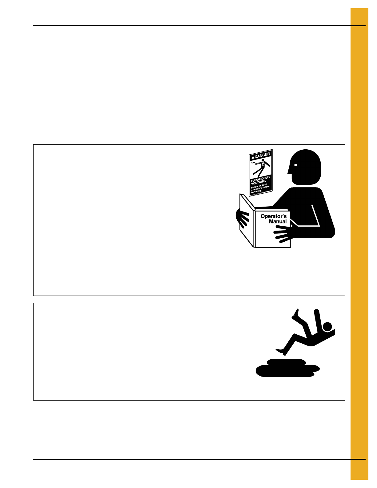
Read and Understand Manual
Practice Safe Maintenance
Understand service procedures before doing work. Keep area
clean and dry.
Never lubricate, service, or adjust machine while it is in operation.
Keep hands, feet, and clothing away from rotating parts.
Keep all parts in good condition and properly installed. Fix
damage immediately . Replace worn or broken p arts. Remove any
built-up grease, oil, and debris.
Maintain Equipment
and Work Area
Safety Instructions
Our foremost concern is your safety and the safety of others associated with this equipment. We want to
keep you as a customer. This manual is to help you understand safe operating procedures and some
problems that may be encountered by the operator and other personnel.
As owner and/or operator, it is your responsibility to know what requirements, hazards, and precautions
exist, and to inform all personnel associated with the equipment or in the area. Safety precautions may be
required from the personnel. Avoid any alterations to the equipment. Such alterations may produce a very
dangerous situation where SERIOUS INJURY or DEATH may occur.
This equipment shall be installed in accordance with the current installation codes and applicable
regulations, which should be carefully followed in all cases. Authorities having jurisdiction should be
consulted before installations are made.
PNEG-1798 Tower and T-Series Dryers Vaporizer 5
Page 6
1. Safety
Prepare for Emergencies
Be prepared if fire starts.
Keep a first aid kit and fire extinguisher handy.
Keep emergency numbers for doctors, ambulance service,
hospital, and fire department near your telephone.
Keep Emergency Equipment
Quickly Accessible
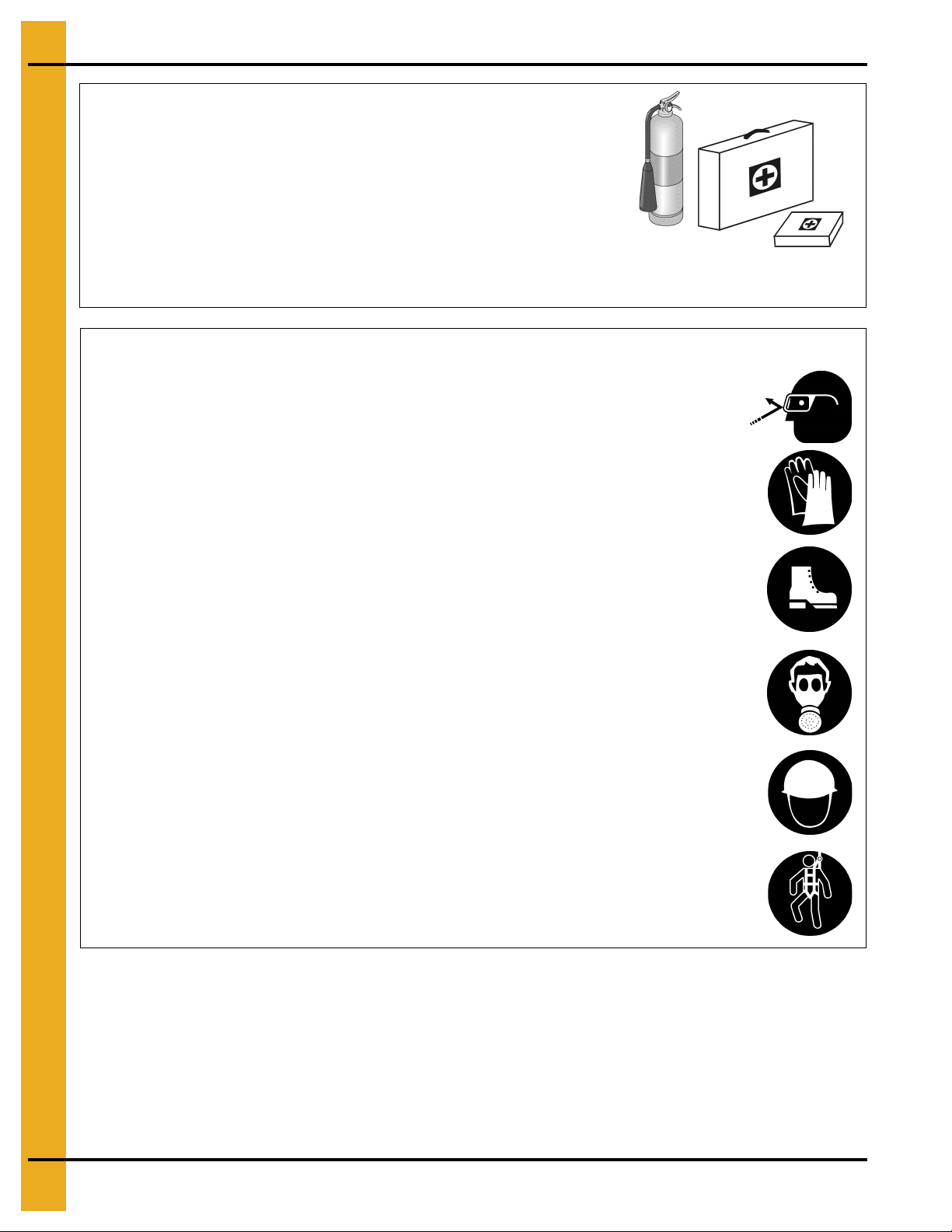
Wear Protective Clothing
Wear close-fitting clothing and safety equipment appropriate
to the job.
Remove all jewelry.
Tie long hair up and back.
Wear safety glasses at all times to protect eyes from debris.
Wear gloves to protect your hands from sharp edges on plastic
or steel parts.
Wear steel-toed boots to help protect your feet from falling
debris. Tuck in any loose or dangling shoestrings.
A respirator may be needed to prevent breathing potentially
toxic fumes and dust.
Wear a hard hat to help protect your head.
Wear appropriate fall protection equipment when working at
elevations greater than six feet (6').
Eye Protection
Gloves
Steel-Toed Boots
Respirator
Hard Hat
Fall Protection
6 PNEG-1798 Tower and T-Series Dryers Vaporizer
Page 7
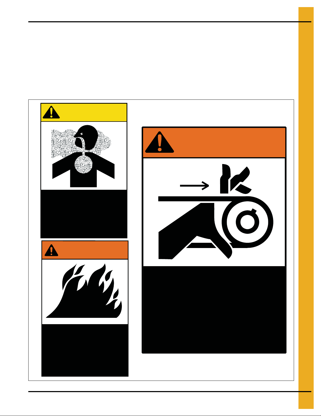
2. Decals
Airborne particles during
operation. May impair
vision and breathing.
Do not enter when
dryer is running.
CAUTION!
DC-1063
Flame and pressure
beyond door. May
cause serious injury.
Do not enter when
dryer is running.
DC-1061
WARNING!
High speed belt drive
operating overhead.
Can cause serious injury.
Keep head and hands
clear. Do not enter when
dryer is running.
WARNING!
DC-1064
The GSI recommends you contact your local power company and have a representative survey yo ur dryer
installation, so your wiring will be compatible with their system and you will have adequate power supplied
to your unit.
Safety decals should be read and understood by all people in and around the dryer area. If the following
safety decals are not displayed on your dryer or if they are damaged, contact the GSI for replacement:
GSI Decals
1004 E. Illinois St.
Assumption, IL. 62510
Phone: 1-217-226-4421
PNEG-1798 Tower and T-Series Dryers Vaporizer 7
Page 8
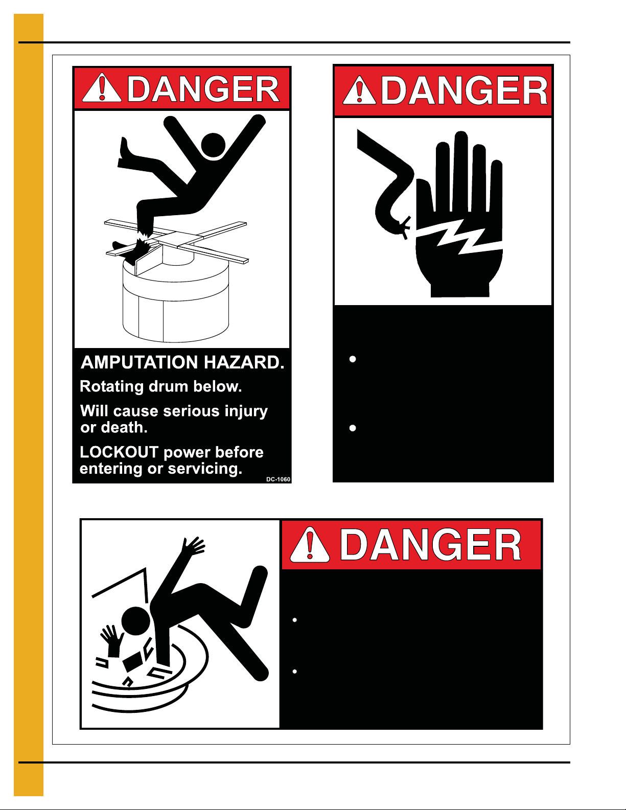
2. Decals
DC-1062
DO NOT STAND ON DRUM!
Rotating drum will cause
serious injury or death.
Disconnect power before
servicing.
HIGH VOLTAGE.
Will cause serious
injury or death.
Lockout power
before servicing.
DC-1224
8 PNEG-1798 Tower and T-Series Dryers Vaporizer
Page 9

3. Purpose
The purpose of this procedure is to provide detailed instructions for the installation and testing of an
internal vaporizer coil assembly and its associated piping utilized on GSI or Zimmerman Tower Dryers and
the T-Series Dryers that use liquid petroleum (LP) as the main fuel source.
PNEG-1798 Tower and T-Series Dryers Vaporizer 9
Page 10

4. Precautions and Limitations
4.1. The installation contractor and its installers shall have experience in properly identifying SCH 80
piping and fittings from SCH 40, cutting, threading and connecting black iron piping used on high
pressure (200 PSIG) liquid petroleum (LP) systems.
4.2. Metals with sharp edges are present and installers should be aware of these at all steps during the
installation process.
4.3. Verify that the main power to the dryer control panel (if installed) is de-energized and locked out.
4.4. Verify that the main gas train has been installed prior to performing this procedure, it must be installed
to make the final connections for the vaporizer inlet and outlet piping and the 2" burner supply line
must be verified as being vertically plumb on the outside of the dryer.
10 PNEG-1798 Tower and T-Series Dryers Vaporizer
Page 11

5. References
5.1. PNEG-707, Commercial Tower Dryer - GSI Construction Manual
5.2. PNEG-1458, T-Series Tower Dryer - Operation Manual
5.3. PNEG-526, Tower Dryer 2009 - GSI Operation and Service Manual
NOTE: The PNEG manuals listed above in Steps 5.1-5.3 are available at the following GSI website
link; http://www.grainsystems.com/literature/manuals/conditioning_manuals.php
5.4. GSI Drawing #: Vaporizer train
PNEG-1798 Tower and T-Series Dryers Vaporizer 11
Page 12

6. Measuring and Special Equipment Required
6.1. Nitrogen gas, large cylinder.
6.2. Regulator, single stage with CGA 580 fitting, nitrogen gas service with gauges. (Must regulate to
200 PSIG - See Page 25.)
6.3. Hose with fittings on each end, high pressure (rated for > 500 PSIG).
6.4. Gauge, pressure (0-300 PSIG) or equivalent digital electronic pressure transducer or pressure
transmitter with readout device.
6.5. Power cord 16/3 AWG or 14/3 AWG with 120 VAC 3 prong plug on one end, bare wires and wire nuts
for the other end. (This will be used to power the 3/4" normally closed ASCO liquid line solenoid valve
during leak testing in Page 25, Step 7.4.6 on Page 26.)
6.6. Leak test solution, industrial grade. (To detect nitrogen gas leaks.)
6.7. Pipe cutting and threading equipment for 2", 1-1/4" and 3/4" piping.
6.8. Pipe thread sealant, industrial grade with PTFE and/or teflon tape.
12 PNEG-1798 Tower and T-Series Dryers Vaporizer
Page 13

7. Procedure
7.1. Dryer Data Information (from its GSI Data Plate)
7.1.1. Record the model # of the dryer on the TD-VIP-01 data sheet. (Hereafter referred to as the
data sheet.)
7.1.2. Record the serial # of the dryer on the data sheet.
7.1.3. Record the panel voltage required on the data sheet.
7.1.4. Record the panel current (amperage) on the data sheet.
7.1.5. Record the customer’s name on the data sheet.
7.1.6. Record the dryer location on the data sheet.
7.1.7. Record the name of the company performing the vaporizer installation.
7.2. Vaporizer Hardware Verification
NOTE: To perform the installation process in an efficient manner the hardware and piping that is
necessary should be verified as being available and on site prior to starting the installation. Any
items that were not located must be reported to the GSI project management group as soon as
possible to schedule delivery.
Refer to vaporizer train drawing that is attached as appendix ‘A’ in this procedure for hardware
items and their position in the train.
7.2.1. Verify that there are (3 ea.) 21' lengths of 1-1/4" SCH 80 black iron pipe. (Record this on the
data sheet.)
7.2.2. Verify that there are (3 ea.) 21' lengths of 3/4" SCH 80 black iron pipe. (Record this on the
data sheet.)
7.2.3. Verify that there is actually a vaporizer coil assembly pre-mounted or positioned unsecured above
the burner of the dryer. (See Figure 7A.) (Record this on the data sheet.)
Figure 7A Vaporizer Coil
PNEG-1798 Tower and T-Series Dryers Vaporizer 13
Page 14

7. Procedure
7.2.4. Verify that there is brass 3/4" manual isolation ball valve in the kit. (See Figure 7B.) (Record this
on the data sheet.)
Figure 7B 3/4" Manual Isolation Ball Valve
7.2.5. Verify that there is a 3/4" strainer assembly in the kit. (See Figure 7C.) (Record this on the
data sheet.)
Figure 7C 3/4" In-Line Strainer Assembly
14 PNEG-1798 Tower and T-Series Dryers Vaporizer
Page 15

7. Procedure
7.2.6. Verify that there is brass body 3/4" ASCO liquid solenoid valve in the kit. (See Figure 7D.) (Record
this on the data sheet.)
Figure 7D 3/4" ASCO Liquid Line Solenoid Valve (Normally Closed)
7.2.7. Verify that there is brass 3/4" pressure relief valve and a 3/4" to 1/4" bushing in the kit.
(See Figure 7E.) (Record this on the data sheet.)
Figure 7E 3/4" Brass Pressure Relief Valve Assembly
PNEG-1798 Tower and T-Series Dryers Vaporizer 15
Page 16

7. Procedure
7.2.8. Verify that there are (2 ea.) 2-1/2" diameter, liquid filled, 0-200 PSIG, 1/4" NPT bottom mount
pressure gauges. Gauges will require (2 ea.) 3/4" to 1/4" reducing bushings that are mounted in
the 3/4" SCH 80 tees. (See Figure 7F.) (Record this on the data sheet.)
Figure 7F Pressure Gauge (0-200 PSIG)
7.2.9. Verify that there are (3 ea.) 3/4" SCH 80 tees for the two (2) pressure gauges and one for the
pressure relief valve mounting. (Record this on the data sheet.)
7.2.10. Verify that there are (3 ea.) 3/4" to 1/4" SCH 80 bushings for the two (2) pressure gauges and one
for the pressure relief valve mounting. (Record this on the data sheet.)
7.2.11. Verify that there are at least (6 ea.) SCH 80 1-1/4" 90’s (elbows). (Record this on the data sheet.)
7.2.12. Verify that there are at least (6 ea.) SCH 80 3/4" 90’s (elbows). (Record this on the data sheet.)
7.2.13. Verify that there are at least (7 ea.) SCH 80 1-1/4" unions. (Record this on the data sheet.)
7.2.14. Verify that there are at least (7 ea.) SCH 80 3/4" unions. (Record this on the data sheet.)
7.2.15. Verify that there are at least (2 ea.) 3/4" SCH 80 45º and (2 ea.) 1-1/4" SCH 80 45º fittings.
(Record this on the data sheet.)
7.2.16. Verify that there is at least (1 ea.) SCH 80 1-1/4" x 3/4" reducer. (Record this on the data sheet.)
7.2.17. Verify that there is at least (1 ea.) SCH 80 2" x 1-1/4" reducer. (Record this on the data sheet.)
7.2.18. Verify that there are at least (2 ea.) SCH 40 2" x 4" L nipples. (Record this on the data sheet.)
7.2.19. Verify that there are at least (2 ea.) SCH 40 2" x 24" L nipples. (Record this on the data sheet.)
7.2.20. Verify that there are at least (2 ea.) 2" U-bolts. (Record this on the data sheet.)
7.2.21. Verify that there are at least (8 ea.) 1-1/4" U-bolts. (Record this on the data sheet.)
7.2.22. Verify that there are at least (4 ea.) 3/4" U-bolts. (Record this on the data sheet.)
16 PNEG-1798 Tower and T-Series Dryers Vaporizer
Page 17

7. Procedure
7.2.23. Verify that there are vaporizer coil mounting brackets (four (4) pair) in the kit or installed on the
coil, if it has been installed at the factory. (See Figure 7G and Figure 7H.)
7G + 7H = 1 pair
(Record this on the data sheet.)
Figure 7G Vaporizer Mounting Bracket
Figure 7H Vaporizer Mounting Bracket
NOTE: There are various specific lengths of pipe that must be cut and threaded for all installations
depending on how the pipe train has been installed and how the piping comes through the screen
window for its vertical run down the dryer.
PNEG-1798 Tower and T-Series Dryers Vaporizer 17
Page 18

7. Procedure
CAUTION
All threaded pipe fittings must be screwed tightly to prevent leaking. Industrial
grade pipe thread compound with PTFE and/or teflon t ape in combination with the
thread compound shall be used and liberally applied to all threaded fittings. Large
pipe wrenches (24" and 36") must be used to get the needed torque for tighteni ng
the fittings. Due to limited access to some spaces, piping pieces may need to be
fabricated on the ground and then installed where a pipe wrench can be fully
utilized for tightening.
7.3. Vaporizer Coil and Piping Installation
Information
The vaporizer coil is a very heavy piece of equipment; care should be taken in positioning it for mounting
and the actual mounting process. The coil consists of four (4) coils with an inlet opening for the liquid
propane and an outlet or discharge opening for the ‘vaporized’ heated propane gas. The vaporizer coil
assembly is constructed of 1-1/4" SCH 80 thick walled continuous black iron tubing and has two (2)
1-1/4" male NPT threaded ends.
The ‘inlet’ for the vaporizer is the bottom
coil assembly. (See Figure 7R on Page 24.)
The coil assembly itself is supported by the bracket assembly pieces of Figure 7G and Figure 7H on
Page 17. These pieces are bolted together in a vertical position and then bolted in four (4) equidistant
quadrants of the inside burner can or burner housing assembly. These four (4) brackets will support the
entire set of coils above the burner. The right angle piece of the bracket with four (4) holes is bolted to the
burner can assembly in a vertical position while the other right angle end with seventeen (17) holes is for
the 1-1/4" U-bolts to capture the outside edge of the coil assembly against the bracket. The slots allow for
the brackets to spread apart and butt against the coils.
of the coil assembly and the ‘outlet’ is the top tube of the vaporizer
Figure 7I “Vaporizer Coil” that has not been Mounted above the Burner (Shipped Position)
18 PNEG-1798 Tower and T-Series Dryers Vaporizer
Page 19

7. Procedure
7.3.1. Before running any piping, verify that the 2" burner pipe that has been previously installed through
the screen window and runs vertically along the outside dryer wall is plumb. This is very important
for the keeping the vaporizer piping that will run adjacent to the 2" burner supply line also plumb.
This makes for a professional looking installation when all three (3) pipes have been completed.
The 2" line is in the middle of the arrangement, the 3/4" liquid line is to the left of the 2" line and the
1-1/4" line is to the right of the 2" line. (See Figure 7J.)
Figure 7J Vaporizer and Burner Piping Vertical Outside Run
7.3.2. The vaporizer coil must be moved into a position where two (2) 1-1/4" SCH 80 90º elbows can be
screwed on to the coils inlet and outlet MNPT threaded ends. These elbows must be facing
downward when completed.
7.3.3. Move the coil into a position (if not already positioned) where the vaporizer inlet is to the left of the
2" burner line and the outlet is to the right of the 2" bu rner line. This as viewed looking downward
above the burner on the same side as the burner piping vertical run. The vertical vaporizer lines
begin from here.
PNEG-1798 Tower and T-Series Dryers Vaporizer 19
Page 20

7. Procedure
7.3.4. The inlet is the bottom of the coil and the outlet is the top, the lines can be crossed over outside
the burner can as necessary to get the correct vertical arrangement started downward as soon
as reasonably possible with the best positioning possible. There are no set rule s or procedure for
this, this is a ‘contractor to field run’ item depending on space, fittings and good judgement.
See Figure 7K, Figure 7L below and Figure 7M on Page 21 for a dryer where the piping was
crossed over to get the final vertical arrangement once the piping exited the screen window.
Figure 7K Piping has started on the opposite side of what is desired.
Notice the 2" burner line at the bottom center of the photo.
Figure 7L The liquid line on the left has been reduce d from 1-1/4" to the 3/4" diameter we need
and the piping now exits the inside of the burner can with the 2" burner line located in the center
at the bottom and the 1-1/4" vapor line on the right.
20 PNEG-1798 Tower and T-Series Dryers Vaporizer
Page 21

7. Procedure
Figure 7M The piping has exited the inside of the burner can to the outside of the assembly structure.
These pipes were then crossed at this point due to space and limited access. The 3/4" liquid line is now
to the left of the 2" burner line and the 1-1/4" vapor line is to the right of the 2" burner line.
7.3.5. Vaporizer piping (3/4" and 1-1/4") is now run downward toward the window where the 2" burner
line exits the dryer. Holes must be drilled, punched or cut f or the pipes to penetrate the steel plate
the divides the cooling section from the heating section. (See Figure 7N.)
Figure 7N Piping 3/4", 1-1/4" and 2", going through the steel divider plate.
Notice the use of unions for piping connections.
PNEG-1798 Tower and T-Series Dryers Vaporizer 21
Page 22

7. Procedure
7.3.6. Vaporizer piping (3/4" and 1-1/4") continues downward toward the window where the 2" burner
line exits the dryer. Make sure to anchor the piping at various locations to prevent piping from
moving or creating stress points on fittings due to the vertical hanging weight of this SCH 80 thick
walled pipe. U-bolts and uni-strut with clamps are normally used. See Figure 7O, Figure 7P below
and Figure 7Q on Page 23 for various anchoring examples.
Figure 7O Uni-Strut and Clamps
Figure 7P
22 PNEG-1798 Tower and T-Series Dryers Vaporizer
Page 23
7. Procedure
Figure 7Q Piping Exiting the Window using U-Bolts and Support Brackets
7.3.7. Vaporizer piping (3/4" and 1-1/4") continues downward through the piping window opening and
then vertically and in parallel with the 2" burner supply line toward the gas train.
7.3.8. Continue piping (3/4" and 1-1/4") downward to the gas train. Anchor the vertical run piping in at
least two (2) locations on the outside of the dryer. Uni-strut and clamps are commonly used for this.
7.3.9. Connect the 3/4" vaporizer line to the ga s train liquid supply line. This will allow this section of th e
gas train supply piping and associated components to be pressure tested in
Figure 7R on Page 24
7.3.10. Install a 2" to 1/4" reducing bushing at the end of the 2" to 1-1/4" bell reducer for the connection
of a test gauge. Some test gauges may have a 3/8" MNPT fitting, if so reduce down to allow a for
the test gauge connection size. (See Figure 7R on Page 24.)
7.3.11. Install the 0-300 PSIG test gauge at the reducer bushing fitting of the preceding step. Verify this
gauge has a 0 PSIG reading.
7.3.12. Proceed to vaporizer high pressure leak testing on Page 25.
.
PNEG-1798 Tower and T-Series Dryers Vaporizer 23
Page 24

7. Procedure
Figure 7R Vaporizer Train Piping
24 PNEG-1798 Tower and T-Series Dryers Vaporizer
Page 25

7. Procedure
7.4. Vaporizer High Pressure Leak Testing
Record all steps of this section on the data sheet.
Te sting Information
The vaporizer coil and its associated piping play a vital role in the operation and efficiency of the dryer and
a safety concern for those that operate the dryer. Any leaks pose a potential for disaster and inefficient
operation. This leak test is a way of identifying leaks, large or small, prior to the initial start-up and
operation of the dryer. This test can also be performed at any time during the life of the dryer to verify no
leaks have developed. The performance of this test is also a final verification that any leaks that were
found during this test have been repaired.
The incoming liquid propane (LP) pressure to the dryer is variable and dependent on how full the
customer’s storage tank(s) is, the ambient temperature and how much sun light or shade the tank is
subjected to during the course of a day during dryer usage. Pressures may range from 40 PSIG on very
cold days and 120 PSIG on very warm days with the tank receiving direct sun light for much of the day.
Therefore the vaporizer coil and piping could be subjected to pressures as high as 120 PSIG. It is the intent
of this test to pressurize for leaks at approximately 1.5 times the highest operating pressure of the
vaporizer system. Therefore our target test pressure will be 120 PSIG x 1.5 = 180 PSIG. To go in a
conservative direction the test pressure that will be used for this procedure will be 200 PSIG (+/- 2)
test acceptance criterion is to hold the desired pressure for 3 minutes.
. The
Most common used portable air compressors can only achieve and sustain 80-90 PSIG; this does not
meet the desired target test pressure of 200 PSIG. The nitrogen bottle , gas regulator, high pressure ho se
and 300 PSIG test gauge or instrument of Steps 6.1-6.4 on Page 12 are used for the performance of
this test.
Refer to Figure 7R on Page 24 for locations of connections.
7.4.1. Install a 2" to 1/4" reducing bushing at the end of the 2" to 1-1/4" bell reducer for the connection
of a test gauge. Some test gauges may have a 3/8" or 1/2" MNPT fitting, if so, reduce down to
allow a for the test gauge connection size. (See Figure 7R on Page 24.)
7.4.2. Connect the nitrogen gas regulator to the nitrogen bottle. Turn the regulator handle in a
counterclockwise (CCW) until no resistance is felt on the handle. This is to make sure the
regulator has no output pressure when we open the nitrogen bottle’s valve later in this section.
The regulator’s handle will be turned clockwise (CW) later in this section to give the desired
pressure output.
7.4.3. Connect one end of a high pressure hose assembly (rated for >300 PSIG) to the output side of
the gas regulator installed on the bottle of Step 7.4.2.
7.4.4. Connect the remaining end of the high pressure hose assembly (rated for >300 PSIG) to the inlet
side of the 3/4" gas train liquid supply high pressure isolation valve. The 3/4" valve is shown in
Figure 7B on Page 14.
7.4.5. Tighten both ends of the hose connected in Steps 7.4.3 and 7.4.4. This is where the test pressure
of 200 PSIG will be input.
PNEG-1798 Tower and T-Series Dryers Vaporizer 25
Page 26

7. Procedure
ASCO 3/4" liquid valve solenoid.
NOTE: The ASCO 3/4" liquid valve is a normally closed (N.C.) valve and it must be ‘energized to
open’ for the performance of this test. The valve is activated by 120 volts AC applied to
the two (2) red leads coming from the body of the valve. There will actually be three (3)
wires on the solenoid, two (2) reds and one green wire. (See Figure 7D on Page 15.)
Depending on when the vaporizer is installed; the electrical portion of the dryer may have
been completed prior to this test. The ASCO wires may already be in conduit and
connected to the panel wiring. Regardless of that this test can still be performed. If the
electrical contractor has not completed their portion of the wiring, the wiring will be
exposed as in Figure 7D on Page 15. If the electrical contractor has finished the wiring
there should be a 1/2" conduit LB or tee where the wires from the solenoid valve have
been terminated or connected with wire nuts. The wire nuts can be removed from the
solenoid’s two (2) red wires and one green wire at this location . Note any wire colors and
how they were terminated to ensure they are re-connected exactly ‘as found’.
7.4.6. Connect the 3 prong power cord of 6.5 to the ASCO 3/4" liquid valve wires that were identified in
the note
wires that are disconnected, if applicable will need to be re-connected after the test completion.
Note the wire connections and colors.
preceding this step. Connect the wires as delineated in the following steps. Any field
7.4.7. Connect the 3 prong power cord’s black
an orange wire nut.
7.4.8. Connect the 3 prong power cord’s white
orange wire nut.
7.4.9. Connect the 3 prong power cord’s green
orange wire nut.
7.4.10. Connect or plug the cord’s 3 prong male end into a powered or live 120 volt AC receptacle or
extension cord.
7.4.11. Verify the ASCO liquid solenoid energized open by the audible click or pop at the solenoid valve.
Record that this action occurred on the data sheet.
NOTE: Most larg e nitrogen cylinders when full are approximately 2000-2500 PSIG depending on
the overfill percentage. For the purpose of this test the cylinder bottle’s pressure should
be at least 500-800 PSIG to allow for enough volume to fill the vaporizer coils and
piping and pressure depending on how many leaks there are and how long the system
is pressurized.
7.4.12. Slowly open the nitrogen cylinder’s valve by turning the cylinder’s hand valve knob in a
counterclockwise (CCW) direction. Verify there is a pressure indication on the regulator’s high
pressure gauge. Record the pressure reading on the regulator’s high pressure gauge on the
data sheet.
7.4.13. Close or verify closed the brass 3/4" liquid line manual isolation valve where the nitrogen hose
is connected.
7.4.14. Slowly adjust the regulator mounted on the nitrogen cylinder by turning the regulator’s handle in
clockwise (CW) direction. This should start providing a pressure indication on the regulator’s low
pressure gauge. Continue turning the regulator handle until there is approximately 200 PSIG on
the regulator’s low pressure gauge. Record the pressure reading on the regulator’s low pressure
gauge on the data sheet.
wire to one of the two (2) solenoid’s red wires by using
wire to the solenoid’s remaining red wire by using an
ground wire to the solenoid’s green wire by using an
7.4.15. Using leak detection solution, verify there are no leaks on the nitrogen cylinder’s connection at the
regulator and the regulator gauges or at the hose connection from the regulator or at the
connection to the manual 3/4" manual isolation valve. Repair any leaks that were found before
proceeding to the next step.
26 PNEG-1798 Tower and T-Series Dryers Vaporizer
Page 27

7. Procedure
CAUTION
Prior to attempting any repair of identified leaks, remove the pressure in the
system by closing the valve on the nitrogen cylinder and venting the pressure on
the regulator by turning the handle in a CCW direction. Observe any pressure that
may remain in the system by looking at the regulator gauges, the test gauge and
the 2-1/2" liquid filled 0-200 PSIG liquid line gauge. These gauges must indicate
0 PSIG or pressure is still present in the system. Do not loosen any fittings or
disconnect any lines with pressure on the system.
7.4.16. Verify that the closed 3/4" manual isolation valve is not leaking, by observing that there is still
0 PSIG indicated on the test gauge installed in Step 7.3.11 on Page 23. If there is pressure
indicated on the test gauge the manual 3/4" isolation valve will need replaced. Notify the
cognizant GSI project manager for the correct valve replacement. Record the pressure reading
on the data sheet.
7.4.17. Slowly open the 3/4" manual isolation valve and observe there is a pressure reading on the
0-300 PSIG test gauge. The pressure should increase on the test gauge to approximately
200 PSIG, as was set on the regulator gauge of Step 7.4.14 on Page 26, provided there are no
large or open ended leaks somewhere in the vaporizer system. The nitrogen cylinder regulator
may need to be adjusted to get to the desired t est pressure of 200 PSIG. Record the test gauge
pressure reading on the data sheet.
7.4.18. Using leak detection solution and with the system still pressurized, go to all fittings from the
vaporizer coil connections and inside and outside connections on the vaporizer system and the
liquid line gas train piping from the 3/4" manual isolation valve where the test pressure begins.
Spray or swab the solution liberally and identify any bubbles as leaks that need repaired and the
absence of bubbles as a tight non-leaking connection. Record on the data sheet how many leaks
were initially identified in the performance of this step.
7.4.19. Repair any leaks that were identified. Pressurize the system again as described in the previous
steps and repeat Step 7.4.18 until no bubbles are present, complete this prior to going to
Step 7.4.20.
7.4.20. To verify that all leaks have been repaired and that the vaporizer system is a total leak free closed
loop system, pressurize the system to 200 PSIG (+/- 2) as indicated on the test gauge. Adjust the
regulator to reach this pressure. Record this test pressure value on the data sheet as the
beginning (0 minute) test pressure. Note the time for the beginning of this 3 minutes leak test.
7.4.21. Close the manual 3/4" liquid line valve.
7.4.22. Close the nitrogen bottle supply valve.
7.4.23. Vent the regulator by turning the regulator handle or knob CCW until no pressure is observed on
the regulator’s gauges. The regulator handle or knob may need to be turned CW with the nitrogen
cylinder’s valve still closed to completely vent any remaining pressure.
7.4.24. Verify the pressure that was recorded in Step 7.4.20 has remained stable and has not decreased
or slowly decayed. If the pressure has dropped or decreased in value, as indicated on the test
gauge, a leak is still present in the system and must be repaired prior to going to Step 7.4.25.
7.4.25. The desired test pressure of 200 PSIG (+/- 2) must be held for 3 minutes without decreasing from
the beginning pressure of Step 7.4.20 to the 3 minutes time for a successful leak test. Record the
test pressure from the test gauge after 3 minutes.
7.4.26. Repeat any of the steps from Step 7.4.12 on Page 26 through Step 7.4.25 to achieve the
acceptable leak rate test criteria. Record the ‘as left’ leak rate test times and test gauge pressures
PNEG-1798 Tower and T-Series Dryers Vaporizer 27
on the data sheet. This completed step should be signed and dated on the data sheet by the
person(s) performing the test and a supervisor.
Page 28

7. Procedure
7.4.27. Remove the pressure from the vaporizer loop by disconnecting the nitrogen supply hose
from the 3/4" manual isolation valve and then slowly opening the valve that has been closed
since Step 7.4.21 on Page 27. The test gauge should indicate 0 PSIG when the pressure has
been vented.
7.4.28. Close the manual 3/4" liquid line valve and remove any fittings that remain after the nitrogen hose
was removed in Step 7.4.27. Record this action on the data sheet.
7.4.29. Remove the 0-300 PSIG test gauge and any fittings installed in the 2" x 1" reducer fitting. Record
this action on the data sheet.
7.4.30. Remove the 3 prong 120V AC power cord from the receptacle and then disconnect the wires that
were connected to the ASCO 3/4" liquid line solenoid leads. Re cord this action on the data sheet.
7.4.31. If applicable, re-connect the solenoid lead wires exactly as they were found to the field wires that
were disconnected from the ASCO 3/4" liquid line solenoid in Step 7.4.6 on Page 26. Record this
action on the data sheet.
7.4.32. Remove the high pressure hose and the regulator from the nitrogen cylinder and replace the
protective cap over the cylinder’s valve. Record this action on the data sheet.
7.4.33. Connect the vaporizer 2" female fitting to the system’s high pressure regulator’s inlet side at the
2" nipple. Verify this connection is as tight as possible. Record this action on the data sheet.
7.4.34. Verify all parts of the data sheet have been completed and signed. Copies of the data sheet
should be sent to the GSI project manager for their record keeping.
28 PNEG-1798 Tower and T-Series Dryers Vaporizer
Page 29

TD-VIP-01 Data Sheet
Dryer Information Data (GSI Data Plate)
Step # Information Recorded Data Initials/Date
7.1.1 on Page 13 Model #
7.1.2 on Page 13 Serial #
7.1.3 on Page 13 Panel voltage volts AC
7.1.4 on Page 13 Panel current amps AC
7.1.5 on Page 13 Customer’s name
7.1.6 on Page 13 Dryer location city and state
Vaporizer Hardware Verification Data
Step # Information Recorded Data Initials/Date
7.2.1 on Page 13 (3 ea.) 21' Lengths of 1-1/4" SCH 80 pipe
7.2.2 on Page 13 (3 ea.) 21' Lengths of 3/4" SCH 80 pipe
8. TD-VIP-01 Data Sheet Selection
7.2.3 on Page 13 Vaporizer coil in-place
7.2.4 on Page 14 3/4" Brass manual isolation valve
7.2.5 on Page 14 3/4" Strainer assembly
7.2.6 on Page 15 3/4" ASCO Liquid solenoid valve
7.2.7 on Page 15 3/4" Brass pressure relief valve and 3/4" x 1/4" bushing
7.2.8 on Page 16 (2 ea.) 0-200 PSIG Pressure gauges
7.2.9 on Page 16 (3 ea.) 3/4" SCH 80 tees
7.2.10 on Page 16 (3 ea.) 3/4"-1/4" SCH 80 Bushings
7.2.11 on Page 16 (6 ea.) 1-1/4" SCH 80 90’s
7.2.12 on Page 16 (6 ea.) 3/4" SCH 80 90’s
7.2.13 on Page 16 (7 ea.) 1-1/4" SCH 80 Unions
7.2.14 on Page 16 (7 ea.) 3/4" SCH 80 Unions
7.2.15 on Page 16 (2 ea.) 3/4" and 1-1/4" SCH 80 45’s
7.2.16 on Page 16 (1 ea.) 1-1/4" x 3/4" SCH 80 Reducer
7.2.17 on Page 16 (1 ea.) 2" x 1-1/4" SCH 80 Reducer
7.2.18 on Page 16 (2 ea.) 2" x 4" L SCH 40 Nipples
7.2.19 on Page 16 (2 ea.) 2" x 24" L SCH 40 Nipples
7.2.20 on Page 16 (2 ea.) 2" U-Bolts
7.2.21 on Page 16 (8 ea.) 1-1/4" U-Bolts
7.2.22 on Page 16 (4 ea.) 3/4" U-Bolts
7.2.23 on Page 17 (Four (4) pair) Vaporizer coil mounting brackets
PNEG-1798 Tower and T-Series Dryers Vaporizer 29
Page 30

8. TD-VIP-01 Data Sheet Selection
Vaporizer Pressure Leak Test Data
Step # Information Recorded Data Initials/Date
7.4.1 on Page 25 Bushing installed to accept the 300 PSIG test gauge.
7.4.2 on Page 25
7.4.3 on Page 25 High pressure hose connected to the regulator.
7.4.4 on Page 25 Hose end connected to the 3/4" manual isolation valve input.
7.4.5 on Page 25 Hose ends tightened at regulator and manual valve.
7.4.6 on Page 26
7.4.7 on Page 26 Power cord black wire connected to one of the ASCO red wires.
7.4.8 on Page 26 Power cord white wire connected to the remaining ASCO red wire.
7.4.9 on Page 26 Power cord green wire connected to the ASCO green wire.
7.4.10 on Page 26 Power cord 3 prong male end plugged in a live 120V receptacle.
7.4.11 on Page 26 Audible click or popping sound heard at 3/4" ASCO solenoid.
7.4.12 on Page 26 Regulator high pressure gauge pressure reading. PSIG
7.4.13 on Page 26 3/4" Manual isolation valve ‘CLOSED’.
7.4.14 on Page 26 Regulator low pressure gauge pressure reading. PSIG
7.4.15 on Page 26 No leaks between nitrogen cylinder and input of 3/4" manual valve.
7.4.16 on Page 27 Test gauge reading with 3/4" manual valve ‘CLOSED’. PSIG
Regulator connected to nitrogen cylinder and handle or knob
turned fully CCW.
Power cord available and ready to connect to the 3/4" ASCO
solenoid valve wires.
7.4.17 on Page 27 Test gauge reading with 3/4" manual valve ‘OPEN’. PSIG
7.4.18 on Page 27 Number of leaks initially found before repairs. Leaks
7.4.19 on Page 27 Leaks of 7.4.18 on Page 27 repaired (If applicable).
1. Regulator adjusted to test pressure.
7.4.20 on Page 27
2. 0 Minute test time.
7.4.21 on Page 27 3/4" Manual isolation valve ‘CLOSED’.
7.4.22 on Page 27 Nitrogen cylinder supply valve ‘CLOSED’.
7.4.23 on Page 27 Regulator vented and no pressure indicated on regulator gauges.
7.4.24 on Page 27 Test gauge pressure reading during this step. PSIG
1. Test pressure of Step 7.4.20 on Page 16.
7.4.25 on Page 27
2. 3 Minute test time after time of Step 7.4.20 on Page 16.
7.4.26 on Page 27
‘As found’
beginning of
3 minutes
7.4.26 on Page 27
‘As left’ end of
3 minutes
1. Regulator adjusted to test pressure.
2. 0 Minute test time.
1. Regulator adjusted to test pressure.
2. 0 Minute test time.
1. ______ PSIG
2. ______ Time
1. ______ PSIG
2. ______ Time
1. ______ PSIG
2. ______ Time
1. ______ PSIG
2. ______ Time
30 PNEG-1798 Tower and T-Series Dryers Vaporizer
Page 31

8. TD-VIP-01 Data Sheet Selection
Signatures for Completion of Leak Test
Test Technician: _______________________________________ Date: _________________
Supervisor: ____________________________________________ Date: _________________
Vaporizer Pressure Leak Test Data (Continued)
Step # Information Recorded Data Initials/Date
1. Disconnect hose at 3/4" manual valve.
7.4.27 on Page 28
7.4.28 on Page 28 3/4" Manual isolation valve ‘CLOSED’.
7.4.29 on Page 28 0-300 PSIG test gauge and fittings removed from 2" x 1" reducer.
7.4.30 on Page 28
7.4.31 on Page 28
7.4.32 on Page 28 High pressure hose and regulator removed from nitrogen cylinder.
7.4.33 on Page 28
7.4.34 on Page 28 Verify all steps of this section are complete and initialed and signed.
2. ‘OPEN’ the valve.
3. Verify 0 PSIG on test gauge.
3 Prong cord removed from receptacle and wires disconnected from
ASCO solenoid.
Solenoid wires re-connected to field wires (If applicable)
mark as ‘N/A’ if not.
Connect the 2" x 1" fitting from the vaporizer loop to the 2" inlet fitting
of the high pressure regulator.
1.
2.
3. PSIG
1.
2.
3.
Test Performers Names and Completion Date
Test Performer Name(s) Company Name Test Completion Date Test Performer’s Initials
PNEG-1798 Tower and T-Series Dryers Vaporizer 31
Page 32

NOTES
32 PNEG-1798 Tower and T-Series Dryers Vaporizer
Page 33

9. Warranty
9101239_1_CR_rev7.DOC (revised July 2009)
GSI Group, LLC Limited Warranty
The GSI Group, LLC (“GSI”) warrants products which it manufactures to be free of defects in materials and workmanship
under normal usage and conditions for a period of 12 months after sale to the original end-user or if a foreign sale,
14 months from arrival at port of discharge, whichever is earlier. The end-user’s sole remedy (and GSI’s only obligation)
is to repair or replace, at GSI’s option and expense, products that in GSI’s judgment, contain a material defect in materials
or workmanship. Expenses incurred by or on behalf of the end-user without prior written authorization from the GSI
Warranty Group shall be the sole responsibility of the end-user.
Warranty Extensions:
The Limited Warranty period is extended for the following products:
Product Warranty Period
Performer Series Direct Drive Fan Motor 3 Years
AP Fans and Flooring
Cumberland
Feeding/Watering
Systems
Grain Systems Grain Bin Structural Design 5 Years
Grain Systems
Farm Fans
Zimmerman
All Fiberglass Housings Lifetime
All Fiberglass Propellers Lifetime
Feeder System Pan Assemblies 5 Years **
Feed Tubes (1-3/4" and 2.00") 10 Years *
Centerless Augers 10 Years *
Watering Nipples 10 Years *
Portable and Tower Dryers 2 Years
Portable and Tower Dryer Frames and
Internal Infrastructure †
5 Years
* Warranty prorated from list price:
0 to 3 years - no cost to end-user
3 to 5 years - end-user pays 25%
5 to 7 years - end-user pays 50%
7 to 10 years - end-user pays 75%
** Warranty prorated from list price:
0 to 3 years - no cost to end-user
3 to 5 years - end-user pays 50%
† Motors, burner components
and moving parts not included.
Portable dryer screens included.
Tower dryer screens not included.
GSI further warrants that the portable and tower dryer frame and basket, excluding all auger and auger drive components,
shall be free from defects in materials for a period of time beginning on the twelfth (12
and continuing until the sixtieth (60
th
) month from the date of purchase (extended warranty period). During the extended
th
) month from the date of purchase
warranty period, GSI will replace the frame or basket components that prove to be defective under normal conditions of
use without charge, excluding the labor, transportation, and/or shipping costs incurred in the performance of this
extended warranty.
Conditions and Limitations:
THERE ARE NO WARRANTIES THAT EXTEND BEYOND THE LIMITED WARRANTY DESCRIPTION SET FORTH
ABOVE. SPECIFICALLY, GSI MAKES NO FURTHER WARRANTY OF ANY KIND, EXPRESS OR IMPLIED,
INCLUDING, WITHOUT LIMITATION, WARRANTIES OF MERCHANTABILITY OR FITNESS FOR A PARTICULAR
PURPOSE OR USE IN CONNECTION WITH: (I) PRODUCT MANUFACTURED OR SOLD BY GSI OR (II) ANY ADVICE,
INSTRUCTION, RECOMMENDATION OR SUGGESTION PROVIDED BY AN AGENT, REPRESENTA TIVE OR
EMPLOYEE OF GSI REGARDING OR RELATED TO THE CONFIGURATION, INSTALLATION, LAYOUT, SUITABILITY
FOR A PARTICULAR PURPOSE, OR DESIGN OF SUCH PRODUCTS.
GSI shall not be liable for any direct, indirect, incidental or consequential damages, including, without limitation, loss of
anticipated profits or benefits. The sole and exclusive remedy is set forth in the Limited Warranty, which shall not exceed
the amount paid for the product purchased. This warranty is not transferable and applies only to the original end-user. GSI
shall have no obligation or responsibility for any representations or warranties made by or on behalf of any dealer, agent
or distributor.
GSI assumes no responsibility for claims resulting from construction defects or unauthorized modifications to products
which it manufactured. Modifications to products not specifically delineated in the manual accompanying the equipment at
initial sale will void the Limited Warranty.
This Limited Warranty shall not extend to products or parts which have been damaged by negligent use, misuse, alteration,
accident or which have been improperly/inadequately maintained. This Limited Warranty extends solely to products
manufactured by GSI.
Prior to installation, the end-user has the responsibility to comply with federal, state and local codes which apply to the
location and installation of products manufactured or sold by GSI.
PNEG-1798 Tower and T-Series Dryers Vaporizer 33
Page 34

This equipment shall be installed in accordance with
the current installation codes and applicable
regulations, which should be carefully followed in all
cases. Authorities having jurisdiction should be
consulted before installations are made.
Copyright © 2011 by GSI Group
Printed in the USA
GSI Group
1004 E. Illinois St.
Assumption, IL 62510-0020
Phone: 1-217-226-4421
Fax: 1-217-226-4420
www.gsiag.com
CN-201399
 Loading...